EP1613935B1 - Spectroscopy apparatus and associated technique - Google Patents
Spectroscopy apparatus and associated technique Download PDFInfo
- Publication number
- EP1613935B1 EP1613935B1 EP04721921.7A EP04721921A EP1613935B1 EP 1613935 B1 EP1613935 B1 EP 1613935B1 EP 04721921 A EP04721921 A EP 04721921A EP 1613935 B1 EP1613935 B1 EP 1613935B1
- Authority
- EP
- European Patent Office
- Prior art keywords
- thz
- radiation
- spectrum
- derivative
- frequency spectrum
- Prior art date
- Legal status (The legal status is an assumption and is not a legal conclusion. Google has not performed a legal analysis and makes no representation as to the accuracy of the status listed.)
- Expired - Lifetime
Links
- 238000000034 method Methods 0.000 title claims description 52
- 238000004611 spectroscopical analysis Methods 0.000 title description 6
- 238000001228 spectrum Methods 0.000 claims description 140
- 239000002360 explosive Substances 0.000 claims description 103
- 230000005855 radiation Effects 0.000 claims description 78
- 239000000463 material Substances 0.000 claims description 74
- 238000010521 absorption reaction Methods 0.000 claims description 47
- 230000003595 spectral effect Effects 0.000 claims description 40
- XLYOFNOQVPJJNP-UHFFFAOYSA-N water Substances O XLYOFNOQVPJJNP-UHFFFAOYSA-N 0.000 claims description 32
- 238000001514 detection method Methods 0.000 claims description 26
- 239000000203 mixture Substances 0.000 claims description 25
- 238000004458 analytical method Methods 0.000 claims description 18
- 238000000862 absorption spectrum Methods 0.000 claims description 16
- 230000000694 effects Effects 0.000 claims description 15
- 239000000126 substance Substances 0.000 claims description 12
- 230000001678 irradiating effect Effects 0.000 claims description 6
- 230000005670 electromagnetic radiation Effects 0.000 claims 4
- 239000000523 sample Substances 0.000 description 54
- XTFIVUDBNACUBN-UHFFFAOYSA-N 1,3,5-trinitro-1,3,5-triazinane Chemical compound [O-][N+](=O)N1CN([N+]([O-])=O)CN([N+]([O-])=O)C1 XTFIVUDBNACUBN-UHFFFAOYSA-N 0.000 description 53
- 101001094880 Arabidopsis thaliana Pectinesterase 4 Proteins 0.000 description 27
- 230000005540 biological transmission Effects 0.000 description 15
- 239000004744 fabric Substances 0.000 description 13
- 238000005259 measurement Methods 0.000 description 13
- TZRXHJWUDPFEEY-UHFFFAOYSA-N Pentaerythritol Tetranitrate Chemical compound [O-][N+](=O)OCC(CO[N+]([O-])=O)(CO[N+]([O-])=O)CO[N+]([O-])=O TZRXHJWUDPFEEY-UHFFFAOYSA-N 0.000 description 11
- 239000000026 Pentaerythritol tetranitrate Substances 0.000 description 11
- 230000003287 optical effect Effects 0.000 description 11
- 229960004321 pentaerithrityl tetranitrate Drugs 0.000 description 11
- FYDSPEWNDZOWPU-UHFFFAOYSA-N [3-nitrooxy-2,2-bis(nitrooxymethyl)propyl] nitrate;1,3,5-trinitro-1,3,5-triazinane Chemical compound [O-][N+](=O)N1CN([N+]([O-])=O)CN([N+]([O-])=O)C1.[O-][N+](=O)OCC(CO[N+]([O-])=O)(CO[N+]([O-])=O)CO[N+]([O-])=O FYDSPEWNDZOWPU-UHFFFAOYSA-N 0.000 description 10
- 238000013459 approach Methods 0.000 description 10
- UZGLIIJVICEWHF-UHFFFAOYSA-N octogen Chemical compound [O-][N+](=O)N1CN([N+]([O-])=O)CN([N+]([O-])=O)CN([N+]([O-])=O)C1 UZGLIIJVICEWHF-UHFFFAOYSA-N 0.000 description 9
- 238000003384 imaging method Methods 0.000 description 7
- -1 masonry Substances 0.000 description 6
- 239000004065 semiconductor Substances 0.000 description 6
- 238000000411 transmission spectrum Methods 0.000 description 6
- 230000001419 dependent effect Effects 0.000 description 5
- 230000008859 change Effects 0.000 description 4
- 230000000052 comparative effect Effects 0.000 description 4
- 239000000470 constituent Substances 0.000 description 4
- 239000000835 fiber Substances 0.000 description 4
- 238000000985 reflectance spectrum Methods 0.000 description 4
- 238000012216 screening Methods 0.000 description 4
- 229910001218 Gallium arsenide Inorganic materials 0.000 description 3
- VYPSYNLAJGMNEJ-UHFFFAOYSA-N Silicium dioxide Chemical compound O=[Si]=O VYPSYNLAJGMNEJ-UHFFFAOYSA-N 0.000 description 3
- 239000000123 paper Substances 0.000 description 3
- 239000004033 plastic Substances 0.000 description 3
- 229920003023 plastic Polymers 0.000 description 3
- 239000004014 plasticizer Substances 0.000 description 3
- SPSSULHKWOKEEL-UHFFFAOYSA-N 2,4,6-trinitrotoluene Chemical compound CC1=C([N+]([O-])=O)C=C([N+]([O-])=O)C=C1[N+]([O-])=O SPSSULHKWOKEEL-UHFFFAOYSA-N 0.000 description 2
- XFYYQDHEDOXWGA-UHFFFAOYSA-N 4-[(5-bromopyridin-2-yl)amino]-4-oxobutanoic acid Chemical compound OC(=O)CCC(=O)NC1=CC=C(Br)C=N1 XFYYQDHEDOXWGA-UHFFFAOYSA-N 0.000 description 2
- 229920000742 Cotton Polymers 0.000 description 2
- 239000004698 Polyethylene Substances 0.000 description 2
- 229920002367 Polyisobutene Polymers 0.000 description 2
- 230000002411 adverse Effects 0.000 description 2
- 230000008901 benefit Effects 0.000 description 2
- 230000008878 coupling Effects 0.000 description 2
- 238000010168 coupling process Methods 0.000 description 2
- 238000005859 coupling reaction Methods 0.000 description 2
- 239000008177 pharmaceutical agent Substances 0.000 description 2
- 230000010287 polarization Effects 0.000 description 2
- 229920000573 polyethylene Polymers 0.000 description 2
- 229910052594 sapphire Inorganic materials 0.000 description 2
- 239000010980 sapphire Substances 0.000 description 2
- 238000013519 translation Methods 0.000 description 2
- 238000002834 transmittance Methods 0.000 description 2
- XTWYTFMLZFPYCI-KQYNXXCUSA-N 5'-adenylphosphoric acid Chemical compound C1=NC=2C(N)=NC=NC=2N1[C@@H]1O[C@H](COP(O)(=O)OP(O)(O)=O)[C@@H](O)[C@H]1O XTWYTFMLZFPYCI-KQYNXXCUSA-N 0.000 description 1
- 241000819038 Chichester Species 0.000 description 1
- 206010010144 Completed suicide Diseases 0.000 description 1
- 229910005540 GaP Inorganic materials 0.000 description 1
- 229910000530 Gallium indium arsenide Inorganic materials 0.000 description 1
- 239000007836 KH2PO4 Substances 0.000 description 1
- 229910003327 LiNbO3 Inorganic materials 0.000 description 1
- 229910012463 LiTaO3 Inorganic materials 0.000 description 1
- 229910007709 ZnTe Inorganic materials 0.000 description 1
- 238000002835 absorbance Methods 0.000 description 1
- 238000007792 addition Methods 0.000 description 1
- 229910000147 aluminium phosphate Inorganic materials 0.000 description 1
- LFVGISIMTYGQHF-UHFFFAOYSA-N ammonium dihydrogen phosphate Chemical compound [NH4+].OP(O)([O-])=O LFVGISIMTYGQHF-UHFFFAOYSA-N 0.000 description 1
- 229910002113 barium titanate Inorganic materials 0.000 description 1
- 238000010009 beating Methods 0.000 description 1
- 230000015572 biosynthetic process Effects 0.000 description 1
- 229910052980 cadmium sulfide Inorganic materials 0.000 description 1
- UHYPYGJEEGLRJD-UHFFFAOYSA-N cadmium(2+);selenium(2-) Chemical compound [Se-2].[Cd+2] UHYPYGJEEGLRJD-UHFFFAOYSA-N 0.000 description 1
- 239000011111 cardboard Substances 0.000 description 1
- 239000000919 ceramic Substances 0.000 description 1
- 150000001875 compounds Chemical class 0.000 description 1
- 230000006835 compression Effects 0.000 description 1
- 238000007906 compression Methods 0.000 description 1
- 239000013078 crystal Substances 0.000 description 1
- 230000003247 decreasing effect Effects 0.000 description 1
- 238000013461 design Methods 0.000 description 1
- CSJLBAMHHLJAAS-UHFFFAOYSA-N diethylaminosulfur trifluoride Substances CCN(CC)S(F)(F)F CSJLBAMHHLJAAS-UHFFFAOYSA-N 0.000 description 1
- VJHINFRRDQUWOJ-UHFFFAOYSA-N dioctyl sebacate Chemical compound CCCCC(CC)COC(=O)CCCCCCCCC(=O)OCC(CC)CCCC VJHINFRRDQUWOJ-UHFFFAOYSA-N 0.000 description 1
- 239000006185 dispersion Substances 0.000 description 1
- 238000002474 experimental method Methods 0.000 description 1
- 239000000295 fuel oil Substances 0.000 description 1
- 239000011521 glass Substances 0.000 description 1
- 238000009532 heart rate measurement Methods 0.000 description 1
- 238000005286 illumination Methods 0.000 description 1
- 239000012535 impurity Substances 0.000 description 1
- 238000011065 in-situ storage Methods 0.000 description 1
- 239000004615 ingredient Substances 0.000 description 1
- 238000011835 investigation Methods 0.000 description 1
- 239000007788 liquid Substances 0.000 description 1
- 229910000402 monopotassium phosphate Inorganic materials 0.000 description 1
- 239000003921 oil Substances 0.000 description 1
- 230000010355 oscillation Effects 0.000 description 1
- 230000035515 penetration Effects 0.000 description 1
- 239000005365 phosphate glass Substances 0.000 description 1
- 229920000728 polyester Polymers 0.000 description 1
- GNSKLFRGEWLPPA-UHFFFAOYSA-M potassium dihydrogen phosphate Chemical compound [K+].OP(O)([O-])=O GNSKLFRGEWLPPA-UHFFFAOYSA-M 0.000 description 1
- 239000000843 powder Substances 0.000 description 1
- 230000008569 process Effects 0.000 description 1
- 229910052968 proustite Inorganic materials 0.000 description 1
- 239000010453 quartz Substances 0.000 description 1
- 230000009467 reduction Effects 0.000 description 1
- 238000001055 reflectance spectroscopy Methods 0.000 description 1
- 238000002310 reflectometry Methods 0.000 description 1
- 230000004044 response Effects 0.000 description 1
- 238000005070 sampling Methods 0.000 description 1
- 229910052711 selenium Inorganic materials 0.000 description 1
- SBIBMFFZSBJNJF-UHFFFAOYSA-N selenium;zinc Chemical compound [Se]=[Zn] SBIBMFFZSBJNJF-UHFFFAOYSA-N 0.000 description 1
- 239000000377 silicon dioxide Substances 0.000 description 1
- 239000007787 solid Substances 0.000 description 1
- 229910052714 tellurium Inorganic materials 0.000 description 1
- 238000002235 transmission spectroscopy Methods 0.000 description 1
- 239000000015 trinitrotoluene Substances 0.000 description 1
- 238000012795 verification Methods 0.000 description 1
- 239000002023 wood Substances 0.000 description 1
- XLOMVQKBTHCTTD-UHFFFAOYSA-N zinc oxide Inorganic materials [Zn]=O XLOMVQKBTHCTTD-UHFFFAOYSA-N 0.000 description 1
Images







Classifications
-
- G—PHYSICS
- G01—MEASURING; TESTING
- G01N—INVESTIGATING OR ANALYSING MATERIALS BY DETERMINING THEIR CHEMICAL OR PHYSICAL PROPERTIES
- G01N21/00—Investigating or analysing materials by the use of optical means, i.e. using sub-millimetre waves, infrared, visible or ultraviolet light
- G01N21/17—Systems in which incident light is modified in accordance with the properties of the material investigated
- G01N21/25—Colour; Spectral properties, i.e. comparison of effect of material on the light at two or more different wavelengths or wavelength bands
- G01N21/31—Investigating relative effect of material at wavelengths characteristic of specific elements or molecules, e.g. atomic absorption spectrometry
- G01N21/35—Investigating relative effect of material at wavelengths characteristic of specific elements or molecules, e.g. atomic absorption spectrometry using infrared light
- G01N21/3581—Investigating relative effect of material at wavelengths characteristic of specific elements or molecules, e.g. atomic absorption spectrometry using infrared light using far infrared light; using Terahertz radiation
-
- G—PHYSICS
- G01—MEASURING; TESTING
- G01J—MEASUREMENT OF INTENSITY, VELOCITY, SPECTRAL CONTENT, POLARISATION, PHASE OR PULSE CHARACTERISTICS OF INFRARED, VISIBLE OR ULTRAVIOLET LIGHT; COLORIMETRY; RADIATION PYROMETRY
- G01J3/00—Spectrometry; Spectrophotometry; Monochromators; Measuring colours
- G01J3/28—Investigating the spectrum
- G01J3/42—Absorption spectrometry; Double beam spectrometry; Flicker spectrometry; Reflection spectrometry
-
- G—PHYSICS
- G01—MEASURING; TESTING
- G01N—INVESTIGATING OR ANALYSING MATERIALS BY DETERMINING THEIR CHEMICAL OR PHYSICAL PROPERTIES
- G01N21/00—Investigating or analysing materials by the use of optical means, i.e. using sub-millimetre waves, infrared, visible or ultraviolet light
- G01N21/17—Systems in which incident light is modified in accordance with the properties of the material investigated
- G01N21/25—Colour; Spectral properties, i.e. comparison of effect of material on the light at two or more different wavelengths or wavelength bands
- G01N21/31—Investigating relative effect of material at wavelengths characteristic of specific elements or molecules, e.g. atomic absorption spectrometry
- G01N21/35—Investigating relative effect of material at wavelengths characteristic of specific elements or molecules, e.g. atomic absorption spectrometry using infrared light
- G01N21/3563—Investigating relative effect of material at wavelengths characteristic of specific elements or molecules, e.g. atomic absorption spectrometry using infrared light for analysing solids; Preparation of samples therefor
Definitions
- the present invention relates generally to the field of apparatus and methods for imaging and/or investigating samples in the far-infrared (far-IR)/Terahertz (THz) frequency range. More specifically, the present invention relates to investigating a sample containing an explosive material and obtaining a spectral signature of the sample using radiation in the far-infrared/Terahertz frequency range from 100 GHz to 100 THz.
- the radiation utilised is in the frequency range of 500 GHz to 100 THz and more preferably from 1 THz to 100 THz and most preferably from 700 GHz to 10 THz.
- US Patent Application Number 2001/0033636 discloses a method of detecting explosives in luggage which uses X-rays to determine an average atomic number of a material. The average atomic number is then compared with known average atomic numbers of explosive materials to determine if the material being examined is an explosive. This technique, however is unsuitable for routine-security screening of people as its radiation is ionising.
- THz radiation is suitable for screening people and their possessions as it is non-ionising and can pass through clothing, paper, cardboard, wood, masonry, plastic and ceramics. Therefore, it is safer than x-ray techniques.
- THz radiation could be used to obtain spectral information of explosive materials, as the organic molecular nature of explosives, and their crystalline structure are of the appropriate form. To date, however, this has not been effectively achieved.
- WO 02/17231 relates to a millimetre and sub-millimetre wave imaging system for concealed objects.
- the present invention provides a method as recited in claim 1 and an apparatus as recited in claim 19.
- These aspects of the invention preferably use a laser to drive emitting and detecting devices.
- Laser pulses are much shorter than those which can be generated by electronic means ( ⁇ 200fs compared with 1-2ps).
- the apparatus has a larger usable frequency range than systems based on electronic methods, and accesses higher THz frequencies as well as the lower frequency band (a typical range being 0.1-4THz as compared to 0-450GHz for electronic generation means). It has been found that the higher frequencies accessed via the present invention enables unique features relating to fundamental properties to be extracted from the spectral signatures of explosive materials, aiding in uniquely identifying these materials.
- CW techniques involve the illumination of devices, but this time with multiple CW laser sources, producing an output frequency in the THz band at the difference frequency.
- pulsed techniques higher frequencies can be achieved than by electronic methods.
- CW techniques are advantageous (whether optical or electronic), as they can more easily handle arbitrary target distances.
- this CW technique also comprises determining whether a reference beam at the detector is in phase with the detected radiation and adjusting a delay line by at most 1 ⁇ 2 a period of the detected radiation to achieve an in-phase,
- this CW technique can readily account for arbitrary changes in the THz path length to the detector.
- the analysis of the detected radiation utilising the CW technique comprises obtaining a frequency spectrum at a number of predetermined frequencies and analysing the spectra at the predetermined frequencies to determine if features of known explosive materials are present.
- CW radiation is tunable but monochromatic, which it has been found allows discrete measurements to be made at predetermined key indicative frequencies.
- the analysis of the detected radiation in these aspects of the invention comprises determining whether the detected radiation is indicative of a fundamental property of the explosive material.
- the technique of the present invention involves compensating for the signal due to the member by obtaining the first derivative of a frequency spectrum of the detected radiation
- optical techniques utilised in these aspects of the invention enable the identification of unique spectral signatures of explosive materials, regardless of their orientation or material structure.
- the frequency spectrum is an absorption spectrum or a reflection spectrum. It is also preferable that analysis of the detected radiation further comprises analysing the first derivative of the frequency spectrum at predetermined frequencies to determine if features of known explosive materials/compositions are present. This analysis may involve comparing the spectral intensity at the predetermined frequencies with expected intensities relating to one or more explosive materials/compositions.
- the analysis may involve calculating at least one ratio of absorption intensity of the first derivative of the frequency spectra at first and second predetermined frequencies and comparing with expected intensity ratios relating to one or more explosive materials.
- a plurality of intensity ratios are calculated for the spectral signature from a predetermined set of frequencies.
- One or more of the predetermined frequencies may be selected to correspond to a feature indicative of a fundamental property of an explosive material as well as corresponding to a region of low atmospheric water absorption.
- measures may be applied to reduce water absorption effects in the detected radiation. For example, the effects of water absorption may be reduced by reducing the resolution in the analysis of the detected radiation.
- the above apparatus further comprises a comparator for comparing the calculated spectrum with one or more known spectra of explosive materials or compositions to determine whether a likeness exists.
- the known features are indicative of a fundamental property of the explosive material.
- the present invention is directed towards apparatus and methods for detecting explosive materials or compositions, which includes explosive materials in their pure form or combined with other materials, such as other explosives or plasticisers. It also includes explosive materials or compositions in any form including solid, liquid or gaseous form.
- the detection apparatus may be incorporated in a hand held unit, such as a probe or wand, for detecting and identifying explosives hidden on people, in packages, in bags etc, Such a unit would preferably utilise reflectance spectra.
- the detection apparatus may also be configured in a belt-type scanner for detecting explosives in letters, parcels, packages, bags, luggage etc. Further, the detection apparatus may be incorporated in a walk-through portal for screening people and large objects for explosives. Another application for this detection apparatus is in a stand-off or camera/telescope type system for detecting explosives at a distance, for example to locate suicide bombers and suspected bombs in a large area.
- the radiation irradiating the object is In the Terahertz frequency range of 500 GHz to 100 THz., particularly in the range of 1 THz to 100 THz and more particularly in the range of 700 GHz to 10 THz. It has been found that investigating in these frequency ranges are most preferred, as the spectral features apparent at these higher frequencies are due to fundamental properties of the explosive materials, such as vibrational or phonon states of chemical bonds and molecules.
- THz radiation has a shorter wavelength than microwaves and therefore provides better penetration (less scatter) than microwave and near-infrared wavelengths.
- a terahertz pulsed investigating arrangement which comprises an ultra-short pulse laser 11 which may be, for example, Ti: sapphire, Yb:Er doped fibre, Cr:LiSAF, Yb:silica, Nd:YLF, Nd:Glass, Nd:YAG, Alexandrite Yb:Phosphate Glass QX, Yb:GdCOB, Yb:YAG, Yb:KG d(WO 4 ) or Yb:BOYS laser.
- This laser 11 emits pulses of radiation 13, such as a collimated beam of pulses, each of which comprise a plurality of frequencies.
- the pulses generated by the laser preferably having a pulse duration of less than 200fs.
- the beam of generated pulses is directed into beam splitter 12.
- the beam splitter splits the beam into a pump beam 13, which is used to irradiate the sample, and a probe beam 14, which is used during detection.
- Scanning delay line 16 is a variable optical delay, which in its simplest form comprises two mirrors that serve to reflect the beam through a 180° angle. Using a computer as a controller, these mirrors can be quickly swept backwards and forwards in order to vary the path length of the probe beam 14. In this way the scanning delay line 16 assists in matching the relative path lengths of the pump and probe beams.
- the probe beam is then focussed onto receiver 24 for combining with the Terahertz beam.
- the pump beam 13 is directed onto a source 17.
- this source 17 preferably comprises a GaAs based photoconductive switch.
- GasAs based devices use the principle of photoconductive mixing to generate their THz output.
- the radiation emitted by the emitter 17 is directed via a hyper-hemispherical lens (not shown) towards a first parabolic mirror 18, which is preferably an off axis parabolic (OAP) mirror, as are all the parabolic mirrors referred to herein.
- the beam is then reflected off the first parabolic mirror 18 and onto second parabolic mirror 19, which directs the radiation onto sample 20.
- OAP off axis parabolic
- the sample 20 may be moved relative to the beam of radiation through the focal plane of the THz beam or the beam may be moved relative to the sample or both.
- the sample may be placed on a translation stage 25 to appropriately move the sample.
- This translation stage 25 could move the sample one dimensionally along one axis of movement or through two or three axes of movement.
- the THz radiation that is reflected from sample 20 is collected by third parabolic mirror 21 and onto a fourth parabolic mirror 23 via plain mirror 22.
- the fourth parabolic mirror 23 directs the reflected radiation onto a second hyper-hemispherical lens (not shown) and onto a detector 24, such as an electro-optic detector or a photoconductive detector.
- Photoconductive detectors comprise a detection member which may be, for example, GaAs, InGaAs, Si on Sapphire etc.
- the detection member 24 is used to detect both the amplitude and phase of the radiation emitted from the sample 20.
- the THz radiation 39 from the sample is incident on the back surface of the detection member 24.
- the radiation is collected by a lens (not shown), which may be hemispherical or have another shape.
- the Terahertz radiation 39 incident on the detection member 24 induces a photocurrent through the region between electrodes 26a and 26b, located on the opposing side of the detection member 24, which is being illuminated by the laser radiation.
- the radiation illuminating the region between electrodes 26a and 26b is preferably the probe beam 14, which carries this information.
- the current that can then be detected by the electrodes is proportional to the strength of the THz field 39.
- the electrodes 26a, 26b may be of a simple diode formation embedded in a transmission line. Alternatively, they may be triangular and arranged in the shape of a bow-tie to form a so-called bow-tie antenna. They may also be interdigitated electrodes at the centre of a bow-tie or spiral antenna.
- FIGURE 2 illustrates an alternative pulsed arrangement, whereby the sample is investigated using transmitted radiation rather than reflected radiation and the detector is an EOS detector rather than a photoconductive detector.
- the detector is an EOS detector rather than a photoconductive detector.
- FIGURE 2 it is apparent that a variable delay is introduced to the probe beam 14 and that the pump beam 13 is projected onto the sample in the same manner as was illustrated in FIGURE 1 .
- the sample in FIGURE 2 is now generally perpendicular to the incident pump beam, in order to maximise radiation transmission.
- Transmitted radiation 39 is combined with the probe beam 14.
- One particularly popular way to do this is to use electro-optic sampling (EOS).
- EOS electro-optic sampling
- the transmitted THz beam 39 and the probe beam 14 co-linearly propagate through an EOS detector 40.
- the transmitted radiation 39 passes through the detector 40,which modulates the probe beam 14.
- the EOS detector 40 may be comprised of any material which possesses good non-linear characteristics, such as GaAs or Si based semiconductors and NH 4 H 2 PO 4 , ADP, KH 2 PO 4 , KH 2 ASO 4 , Quartz, AlPO 4 , ZnO, CdS, GaP, BaTiO 3 , LiTaO 3 , LiNbO 3 , Te, Se, ZnTe, ZnSe, Ba 2 NaNb 5 O 15 , AgAsS 3 , proustite, CdSe, CdGeAs 2 , AgGaSe 2 , AgSbS 3 , ZnS, organic crystals such as DAST (4-N-methylstilbazolium).
- any material which possesses good non-linear characteristics such as GaAs or Si based semiconductors and NH 4 H 2 PO 4 , ADP, KH 2 PO 4 , KH 2 ASO 4 , Quartz, AlPO 4 , ZnO, CdS
- the modulated beam is then passed into quarter wave plate 41. This serves to circularly polarise the emitted radiation.
- the circularly polarised light is then fed through a Wollaston prism 42, which divides the polarization of the light onto two orthogonal components. These two orthogonal components are then directed onto balanced photodiode assembly 43.
- the balanced photodiode assembly comprises two photo diodes to respectively detect each of the orthogonal components from the Wollaston prism 42.
- the output of the photodiodes are then linked together such that the balanced photodiode assembly 43 only outputs an electrical signal if there is a difference between the readings of the two photodiodes. This output signal corresponds to the strength of the transmitted THz beam 39,
- the THz beam 39 serves to make the radiation exiting the detector 40 slightly elliptically polarised. This change in the polarization still remains after the radiation is passed through quarter waveplate 41. Extracting the orthogonal components of this radiation using prism 42 causes a different signal to be measured at the two photodiodes, and hence balanced photodiode assembly 43 outputs a signal corresponding to the strength of the THz field.
- EOS detection enables the phase and amplitude of the transmitted radiation to be detected. It is to be appreciated that it will be apparent to those skilled in the art that this type of analysis could be performed for any type of detector.
- FIGURES 1 and 2 it is also possible to combine the arrangements of FIGURES 1 and 2 , whereby both reflected and transmitted radiation from the sample is measured.
- THz beam with another beam of radiation which has substantially the same wavelength or which differs in frequency by at most 10GHz.
- Such combined radiation can be detected using a bolometer, Schottky diode etc.
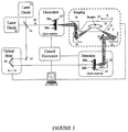
- FIGURE 3 illustrates a CW Terahertz investigating arrangement. To avoid unnecessary repetition in relation to FIGURES 1 and 2 , like reference numerals will be used to denote like features.
- Two laser diodes 30, 31 are configured to emit radiation with frequencies ⁇ 1 and ⁇ 2 respectively.
- the radiation emitted from both laser diodes 30 and 31 is combined using beam splitter/combiner 32.
- the beam splitter 32 creates pump beam 34 and a probe beam 35 each comprising the two beams with frequencies ⁇ 1 and ⁇ 2 .
- the probe beam 35 is fed, via plain mirror 37, into optical delay line 36, which is used as a phase coupling/control means.
- the probe beam 35 is reflected off a cube mirror, which is used to reflect the light through 180°.
- the cube mirror is moveable such that the path length of the probe beam can be varied. Since the probe beam 35 has a known phase relationship to that of the THz radiation, this phase control/coupling means provides the detector 24 with a parameter corresponding to a phase input that can be varied relative to the source beam.
- the optical delay could be positioned so that it varies the phase of the pump beam supplied to an input of the detector 24, with respect to the probe beam.
- This phase control is required as the sample 20 introduces a time delay in the path of the pump beam.
- the delay is dependent on both the absorption coefficient and the refractive index of the sample.
- the frequency component of the probe beam must be in phase with a frequency component of the pump beam in order to obtain a detection signal.
- Variation of optical delay 16 allows the phase of the probe beam and/or pump beam to be swept with respect to the pump beam and/or probe beam and thus allows for measurement of the delay time of each frequency component which passes through the sample.
- the pump beam 34 which comprises radiation with frequencies ⁇ 1 and ⁇ 2 , irradiates the emitter 33.
- the pump beam impinges on the semiconductor emitter 33 on the part of its surface between the electrodes 38a and 38b, i.e. where the field is applied.
- the beating of the two visible or near-infrared lasers in the non-linear region of the semiconductor emitter between the two electrodes 38a and 38b results in the emission of THz radiation from the semiconductor emitter 33.
- the emitter 33 is provided with a lens (not shown), which may be of a hemispherical or other design, on its surface opposite to that of the surface with the electrodes, to allow the emission of a beam of THz radiation.
- the emitted radiation is focussed onto the sample 20.
- the investigating technique illustrated gathers reflected THz radiation and the detector illustrated in FIGURE 3 is a photoconductive detector. Both the irradiating technique and the detector are as described in relation to FIGURE 1 .
- THz CW detecting apparatus over the THz pulsed detecting apparatus is that the CW apparatus can readily account for arbitrary changes in the THz path length, from the beam splitter to the detector.
- the beam from the laser is split into a pump beam 13 and a probe beam 14.
- the THz pulse 29 and probe beam from the laser must arrive at the detector at the same time.
- This simultaneous timing is achieved through the use of the variable delay 16. That is, the THz path length from the beam splitter to the THz generator to the detector via the sample is known or can be determined, and an appropriate delay added to the probe beam 14 so that it arrives at the detector at the same time.
- CW investigating apparatus In CW systems, a beam (cos ( ⁇ 1 t)) from a first laser 30 and a beam (cos ⁇ 2 t) from a second laser 31 are combined to provide optical power at both the emitter and detector.
- This instantaneous optical power varies as (cos[( ⁇ 1 - ⁇ 2 )t] cos[( ⁇ 1 + ⁇ 2 )t]) including a term that varies at the sum frequency and a term that varies at the difference frequency.
- the sum frequency is not relevant, as neither the detector material itself, nor its metallic contacts respond this quickly. They can, however, follow the difference frequency.
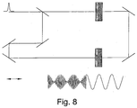
- FIGURE 8 illustrates a simplified schematic of a CW detection apparatus and showing the difference frequency as an overtone arriving at the detector 24 in phase with the sinusoidal emitted THz frequency.
- the arrangements in FIGURES 1 to 3 can adapted as required.
- the arrangements could be configured to focus on a region and irradiate whatever object or objects lie in that region.
- the THz pulses detected at the detector can be analysed to provide various information about the irradiated object in the time and frequency domains. For example, time-of-flight measurements of radiation reflected off the rear surface of an object provides quasi-absorption information.
- transmittance which is the ratio of transmitted to incident radiation at a particular frequency, is determined by the thickness and absorption coefficient of the irradiated object and absorbance is the logarithm of the inverse transmittance.
- the detected THz pulse (which is a function of the optical delay) is Fourier transformed to yield a spectral function of frequency.
- FIGURES 4 to 7 show spectra obtained using the FIGURE 2 apparatus to investigate a number of materials containing explosives in a controlled environment. The samples were held in an evacuated space to eliminate water absorption and the spectra were taken in transmission.
- the materials characterised by this method can be separated into individual explosive chemicals, and explosives containing a either a combination of these, or the base ingredient plus other compounds.
- the measured individual explosives were:
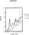
- FIGURE 4 is a comparative graph showing the transmission spectra of these individual explosive compositions.
- the samples of less than 100% purity were powders, and were prepared for measurement in tablet form by compression with polyethylene.
- Polyethylene has a flat spectral response in the frequency range 0-3THz, and so the spectral features in FIGURE 4 are those of the explosive component.
- the spectrum, labelled A illustrates the absorption of the sample containing approximately 25% RDX.
- the absorption spectrum has quite marked and distinctive peaks at frequencies of approximately 0.75, 1.4, 1.95 and 2.9 THz.
- the peak at 1.95 THz is in fact a double peak, although this is not readily apparent in FIGURE 4 in view of the resolution used.
- the spectrum labelled B is for a composition of approximately 25% PETN and has two definite peaks at 1.95 and 2.8 THz.
- the spectrum labelled C is for a composition containing pure TNT. This composition has definite peaks at 1.6 and 2.15 THz with evidence of weaker spectral features between 0.25 and 1.25 THz.
- the remaining spectrum, labelled D, is for a composition containing approximately 25% HMX. This spectrum has definite peaks at 1.75, 2.45 and 2.9 THz.
- FIGURE 5 is another comparative graph, showing the transmission spectra of selected individual explosives - as appear also in figure 4 - along with those from combined explosives.
- the combined explosives are those that are commonly used, typically representing military plastic explosives. These are as follows:
- the spectra for Semtex, PE-4 and SX2 are labelled A,B and C respectively, and those for RDX, PETN and HMX are labelled D, E and F respectively.
- the spectra for D, E, and F correspond to the same spectra, marked A, B, and D respectively on figure 4 , except with a different scale on the absorption axis.
- HMX The presence of the HMX spectrum, F, in Figure 5 , is related to that of the Semtex, labelled A.
- RDX can be manufactured in one of two ways, one of which leaves the chemical with trace quantities of HMX, the other which can incorporate up to 9% of HMX as an impurity (REF " Forensic and Envoronmental detection of Explosives, J. Yinon, John Wiley and Sons Ltd (Chichester, England), 1999 ).
- HMX has a spectral feature at this frequency, and it is plausible therefore that the RDX present within the Semtex sample contained measurable quantities of HMX, whereas the pure RDX explosive did not.
- the materials can still be identified by calculating intensity ratios at the other frequencies since this allows comparison with known and expected ratios for both RDX and PETN. In this manner the presence of certain materials can be verified even if the complete spectra is not available.
- the first derivative of the spectrum may be calculated and mapped. This is a key feature, as it allows unique features of an explosive material's spectrum to be highlighted from beneath materials such as cloth.
- FIGURE 6 compares the spectrum for a 0.5mm thick piece of polyester/cotton cloth, being the lower, less absorptive, spectrum, against the spectrum for a piece of cloth combined with a 0.7mm piece of PE-4 explosive.
- the spectrum for the cloth alone has almost linear gradient. Taking the first derivative of this spectrum, would essentially result in a constant.
- the cloth plus PE-4 spectrum can be considered as essentially the sum of the cloth spectrum and the PE-4 spectrum individually, by taking the first derivative of the combined spectrum, the effect of the cloth can be effectively removed.
- FIGURE 7 the first derivative of the spectum for the cloth plus PE-4 combination of FIGURE 6 . is illustrated. This first derivative is compared with the first derivative of the spectrum of RDX alone (RDX is the main constituent of PE-4 (i.e. 90%)). This graph again shows peaks in the same regions, confirming the similarities in the fundamental properties in the spectra.
- the determination that an explosive material exists can be made by a detailed knowledge of the expected spectra. This may be achieved by comparing the ratios of the intensities measured at a number of different key indicative frequencies across the spectral range. This simplifies the analysis of the spectra required.
- reflection spectroscopy is another approach which can be utilised.
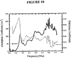
- FIGURE 10 As a general illustration that the unique spectral features visible in absorption are also manifested in reflection, well established mathematical formulae relating to absorption and reflection were utilised to produce the reflection spectrum for PE-4 illustrated in FIGURE 10 .
- the absorption spectrum for PE-4 which was measured using the apparatus of FIGURE 2 , is shown in black.
- FIGURE 11 illustrates spectra measured from an apparatus of the type depicted in FIGURE 1 , which is a reflection THz imaging and spectroscopy apparatus, and in which the sample is held in a normal atmosphere.
- the upper curve is that from a mirror held at the focal plane, and provides a reference for the power spectrum of the apparatus.
- the lower curve is a measured reflectance power spectrum for PE-4.
- the arrows point to the frequencies at which spectral features are expected, around 0.8, 1.5 and 2.3 THz. These expected spectral feature frequencies were calculated from the measured absorption spectrum of FIGURE 10 , and are also in close agreement with the features measured in the transmission spectrum shown in FIGURE 5 (labelled A). The correlation of these frequencies with the observed dips in THz power in the reflectance power spectrum, particularly around 0.9THz, illustrates that reflective spectroscopy, like transmissive spectroscopy, can be used to uniquely identify explosives.
- FIGURES 4 to 9 were taken on an ideal apparatus, depicted in FIGURE 2 , which involves transmission through a vacuum. These measurements showed that THz transmission spectroscopy does produce spectra dependent upon fundamental properties of explosive materials. Where the same techniques are utilised for explosives detection performed through a real atmosphere, the spectra would include water absorption. Therefore, in a real atmosphere, it may be necessary to remove the effects of water absorption from the transmission spectrum or spectra obtained.
- FIGURE 13 a measured THz power spectrum, measured using the transmission apparatus depicted in FIGURE 2 , but in the absence of any sample, is illustrated in black. This was also measured in the absence of air.
- the grey power spectrum represents a calculation of the expected spectrum, including this measured spectrum and adding the absorbing effects of a passage of the THz radiation through 5 m of air (The measured water absorption of air in this frequency range is presented in FIGURE 12 ). Comparing this spectrum represented in grey with the spectrum in an evacuated environment, it is apparent that water vapour adversely affects the overall spectrum to a substantial degree.
- frequencies at which features indicative of Semtex and/or PE4 can be determined are indicated by dotted lines. A number of these frequencies correspond with these atmospheric water absorption windows. Therefore, a detector for identifying these explosives could obtain transmission or reflectance spectra and analyse the spectra at these frequencies, without requiring counter-measures for water absorption, and still be able to accurately detect features indicative of such explosives.
- one approach involves mathematically removing the water absorption component from a spectrum. This could easily be achieved by measuring a known water absorption line (or lines) in a spectrum, and calculating the comparative absorption that would produce such a spectral feature. From this calculation, and from the fact that the water absorption lines within the measured spectrum of FIGURE 12 are always present at known fixed ratios, it is possible to mathematically eliminate the water absorption effects across the whole range of the frequency spectrum.
- FIGURE 12 represents the measured full spectrum from a pulsed THz experiment. With this knowledge it is only necessary to measure THz absorption at the two frequencies indicated by the two arrows. The ratio of these two spectral intensity measurements allows a complete water spectrum to be calculated.
- FIGURE 14 illustrates a THz power spectrum obtained for PE-4.
- the resolution of the frequency spectrum is related to the range of the pulse measurement. Therefore, by arbitrarily curtailing the data set of the pulse for the Fourier transform, the resolution of the frequency power spectrum is reduced.
- the data set (and hence resolution) is progressively reduced, from largest data set (highest resolution) for the bottom curve, to smallest data set (lowest resolution) at the top.
- time-of-flight measurements it is also possible to utilise time-of-flight measurements to determine whether an explosive material exists.
- radiation reflected off the rear surface of an object provides quasi-absorption information. This is because the passage of the radiation through the object will provide a measurement relating to the absorption of the material.
- the beams may be delivered to the emitter, the detector and the irradiating apparatus by any means, including via fiber optics.
- any means including via fiber optics.
- dispersion compensation schemes and appropriate focussing optics into and out of the fibers may be employed.
Landscapes
- Physics & Mathematics (AREA)
- Spectroscopy & Molecular Physics (AREA)
- General Physics & Mathematics (AREA)
- Health & Medical Sciences (AREA)
- Life Sciences & Earth Sciences (AREA)
- Chemical & Material Sciences (AREA)
- Analytical Chemistry (AREA)
- Biochemistry (AREA)
- General Health & Medical Sciences (AREA)
- Immunology (AREA)
- Pathology (AREA)
- Toxicology (AREA)
- Investigating Or Analysing Materials By Optical Means (AREA)
Description
- The present invention relates generally to the field of apparatus and methods for imaging and/or investigating samples in the far-infrared (far-IR)/Terahertz (THz) frequency range. More specifically, the present invention relates to investigating a sample containing an explosive material and obtaining a spectral signature of the sample using radiation in the far-infrared/Terahertz frequency range from 100 GHz to 100 THz. Preferably the radiation utilised is in the frequency range of 500 GHz to 100 THz and more preferably from 1 THz to 100 THz and most preferably from 700 GHz to 10 THz.
- It is well established that many chemicals and pharmaceutical agents have spectral signatures in the THz region. The reason for the spectral signals in this frequency range is considered to be associated with inter-molecular or intra-molecular crystalline vibrations or collective phonon oscillations. It is known that in THz spectroscopy the spectral information of transmitted and/or scattered radiation can be used to identify materials. Most materials interact with terahertz waves to some degree, and each material has its own frequency pattern, which can be considered as a kind of 'fingerprint'.
- Of late security concerns have increased the need for a system that is able to identify hidden explosives, such as under a person's clothing, in a person's suitcase or in a postal package.
-
US Patent Application Number 2001/0033636 discloses a method of detecting explosives in luggage which uses X-rays to determine an average atomic number of a material. The average atomic number is then compared with known average atomic numbers of explosive materials to determine if the material being examined is an explosive. This technique, however is unsuitable for routine-security screening of people as its radiation is ionising. - In a paper entitled "Spectroscopy with electronic terahertz techniques" by D.W. van der Weide et al published in Proc Spie 3828 (99), electronic pulses in the microwave range, up to 450GHz, are used to investigate explosives. These pulses are generated electronically using non-linear transmission lines, coupled with varactor diodes that are patterned on a semiconductor. A sine wave is applied to the transmission line and the result at the other end is a rapid (1-2 ps) voltage step, which is used to produce the microwave pulse from the semiconductor device. This paper demonstrates spectral features of explosives, but only in the sub-terahertz or microwave frequency range.
- Several reflection spectra are illustrated in the paper up to 450 GHz and it is stated that the contrast in the spectra between the different materials probably arises from the granularity of the materials, their dielectric constants and orientation of the sample. Granularity and orientation are both features that are alterable when creating an explosive material. Therefore, if an explosive detector is based on the detection of spectral features dependent on granularity and orientation, explosives could be altered so that the spectral features being identified were masked. This could result in the explosive material passing through the explosive detector unnoticed.
- There is therefore a need for a technique of identifying explosive materials that is not dependent upon alterable spectral features.
- THz radiation is suitable for screening people and their possessions as it is non-ionising and can pass through clothing, paper, cardboard, wood, masonry, plastic and ceramics. Therefore, it is safer than x-ray techniques.
- It has been speculated that THz radiation could be used to obtain spectral information of explosive materials, as the organic molecular nature of explosives, and their crystalline structure are of the appropriate form. To date, however, this has not been effectively achieved.
- There is therefore also a need for a technique for imaging and/or investigating explosive materials using THz radiation.
- One of the problems that needs to be overcome, however, in devising a suitable technique of investigating explosives using THz radiation, is the ability to distinguish explosives from surrounding materials. For example, it is desirable to be able to distinguish plastics explosives from the molecular structure of suitcases or clothing and the like.
- It is therefore an aim of the present invention to overcome or alleviate at least one of the problems of the prior art.
-
WO 02/17231 - In a first aspect, the present invention provides a method as recited in
claim 1 and an apparatus as recited inclaim 19. - These aspects of the invention utilises an optical technique which permits access to high frequency spectral regions where there are unique and intrinsic spectral identifiers, whilst also permitting assessment of lower frequency features,
- These aspects of the invention preferably use a laser to drive emitting and detecting devices. Laser pulses are much shorter than those which can be generated by electronic means (<200fs compared with 1-2ps). In this way the apparatus has a larger usable frequency range than systems based on electronic methods, and accesses higher THz frequencies as well as the lower frequency band (a typical range being 0.1-4THz as compared to 0-450GHz for electronic generation means). It has been found that the higher frequencies accessed via the present invention enables unique features relating to fundamental properties to be extracted from the spectral signatures of explosive materials, aiding in uniquely identifying these materials.
- Some embodiments of the present invention use a CW (Continuous Wave) technique. CW techniques involve the illumination of devices, but this time with multiple CW laser sources, producing an output frequency in the THz band at the difference frequency. As with pulsed techniques, higher frequencies can be achieved than by electronic methods. Furthermore, CW techniques are advantageous (whether optical or electronic), as they can more easily handle arbitrary target distances.
- Preferably this CW technique also comprises determining whether a reference beam at the detector is in phase with the detected radiation and adjusting a delay line by at most ½ a period of the detected radiation to achieve an in-phase,
- Therefore, advantageously this CW technique can readily account for arbitrary changes in the THz path length to the detector.
- Preferably the analysis of the detected radiation utilising the CW technique comprises obtaining a frequency spectrum at a number of predetermined frequencies and analysing the spectra at the predetermined frequencies to determine if features of known explosive materials are present. In this regard, CW radiation is tunable but monochromatic, which it has been found allows discrete measurements to be made at predetermined key indicative frequencies.
- Preferably the analysis of the detected radiation in these aspects of the invention comprises determining whether the detected radiation is indicative of a fundamental property of the explosive material.
- Where the explosive material or composition is covered with a member, such as hidden in a bag or suitcase or under a person's clothing, the technique of the present invention involves compensating for the signal due to the member by obtaining the first derivative of a frequency spectrum of the detected radiation,
- It has been found that where the detection technique is undertaken in relation to detecting explosive materials hidden under clothing or the like, the contribution to the spectra from clothing can be essentially eliminated by determining the first derivative spectra. Hence this feature can allow a spectrum of an explosive material to be accurately obtained.
- It has been found that the optical techniques utilised in these aspects of the invention enable the identification of unique spectral signatures of explosive materials, regardless of their orientation or material structure.
- Preferably, the frequency spectrum is an absorption spectrum or a reflection spectrum. It is also preferable that analysis of the detected radiation further comprises analysing the first derivative of the frequency spectrum at predetermined frequencies to determine if features of known explosive materials/compositions are present. This analysis may involve comparing the spectral intensity at the predetermined frequencies with expected intensities relating to one or more explosive materials/compositions.
- As mentioned above, it is well established that many chemicals and pharmaceutical agents have spectral signatures in the THz region. Since each spectral signature is unique, the ratios of absorption intensity at a distinct set of frequencies are also unique and can be used in identification. As an alternative to the analysis method above therefore, the analysis may involve calculating at least one ratio of absorption intensity of the first derivative of the frequency spectra at first and second predetermined frequencies and comparing with expected intensity ratios relating to one or more explosive materials. Preferably, in such analysis a plurality of intensity ratios are calculated for the spectral signature from a predetermined set of frequencies.
- Analysis of the spectral information by calculating ratios of absorption intensities of the first derivative of the frequency spectra is suitable for both pulsed and CW imaging. However, it is particularly advantageous where imaging is only possible at a limited number of discrete frequencies (as opposed to imaging across the whole frequency range of interest).
- One or more of the predetermined frequencies may be selected to correspond to a feature indicative of a fundamental property of an explosive material as well as corresponding to a region of low atmospheric water absorption. Alternatively, or in addition, measures may be applied to reduce water absorption effects in the detected radiation. For example, the effects of water absorption may be reduced by reducing the resolution in the analysis of the detected radiation.
- It is also preferable that the above apparatus further comprises a comparator for comparing the calculated spectrum with one or more known spectra of explosive materials or compositions to determine whether a likeness exists. Preferably the known features are indicative of a fundamental property of the explosive material.
- The present invention is directed towards apparatus and methods for detecting explosive materials or compositions, which includes explosive materials in their pure form or combined with other materials, such as other explosives or plasticisers. It also includes explosive materials or compositions in any form including solid, liquid or gaseous form.
- The detection apparatus may be incorporated in a hand held unit, such as a probe or wand, for detecting and identifying explosives hidden on people, in packages, in bags etc, Such a unit would preferably utilise reflectance spectra. The detection apparatus may also be configured in a belt-type scanner for detecting explosives in letters, parcels, packages, bags, luggage etc. Further, the detection apparatus may be incorporated in a walk-through portal for screening people and large objects for explosives. Another application for this detection apparatus is in a stand-off or camera/telescope type system for detecting explosives at a distance, for example to locate suicide bombers and suspected bombs in a large area.
- Preferably in these aspects of the invention the radiation irradiating the object is In the Terahertz frequency range of 500 GHz to 100 THz., particularly in the range of 1 THz to 100 THz and more particularly in the range of 700 GHz to 10 THz. It has been found that investigating in these frequency ranges are most preferred, as the spectral features apparent at these higher frequencies are due to fundamental properties of the explosive materials, such as vibrational or phonon states of chemical bonds and molecules.
- A further advantage of using THz radiation is that it has a shorter wavelength than microwaves and therefore provides better penetration (less scatter) than microwave and near-infrared wavelengths.
- The present invention will now be described with reference to the accompanying drawings in which:
-
FIGURE 1 illustrates a schematic of a pulsed terahertz reflection investigative technique utilised in a first embodiment of the present invention; -
FIGURE 2 illustrates a schematic of a pulsed terahertz transmission investigative technique utilised in a second embodiment of the present invention; -
FIGURE 3 illustrates a schematic of a continuous wave terahertz investigative technique utilised in a third embodiment of the present invention; -
FIGURE 4 illustrates transmission absorption spectra for four explosive compositions of different concentrations obtained using an embodiment of the present invention; -
FIGURE 5 illustrates transmission absorption spectra for a number of different explosive compositions obtained using an embodiment of the present invention; -
FIGURE 6 illustrates transmission absorption spectra for an explosive composition, PE-4, and the same explosive composition covered by cloth; -
FIGURE 7 illustrates the first derivative of the PE-4 covered by cloth spectra ofFIGURE 6 and compares that to the first derivative of RDX, being the main constituent of the PE-4; -
FIGURE 8 illustrates a schematic of a CW arrangement and the phase relationship between the pump beam and the probe beam at the detector; -
FIGURE 9 illustrates transmission absorption spectra for various clothing materials; -
FIGURE 10 illustrates a measured absorption spectrum for PE-4 and a corresponding mathematically calculated reflection spectrum; -
FIGURE 11 illustrates reflectance power spectra for explosive material PE-4 and for a reference; -
FIGURE 12 illustrates the absorption spectrum for water vapour; -
FIGURE 13 compares a THz power spectrum measured in an evacuated environment with the corresponding THz power spectrum calculated to include passage through 5m of air in normal atmospheric conditions; and -
FIGURE 14 THz power spectra for PE-4 with varying resolutions. -
FIGURES 1 to 3 illustrate three different terahertz investigating arrangements that may be adapted for use in an explosive detecting apparatus. - Referring to
FIGURE 1 , a terahertz pulsed investigating arrangement is illustrated, which comprises anultra-short pulse laser 11 which may be, for example, Ti: sapphire, Yb:Er doped fibre, Cr:LiSAF, Yb:silica, Nd:YLF, Nd:Glass, Nd:YAG, Alexandrite Yb:Phosphate Glass QX, Yb:GdCOB, Yb:YAG, Yb:KG d(WO4) or Yb:BOYS laser. Thislaser 11 emits pulses ofradiation 13, such as a collimated beam of pulses, each of which comprise a plurality of frequencies. The pulses generated by the laser preferably having a pulse duration of less than 200fs. - The beam of generated pulses is directed into
beam splitter 12. The beam splitter splits the beam into apump beam 13, which is used to irradiate the sample, and aprobe beam 14, which is used during detection. - The
probe beam 14 is directed, viaplain mirror 15, intoscanning delay line 16.Scanning delay line 16 is a variable optical delay, which in its simplest form comprises two mirrors that serve to reflect the beam through a 180° angle. Using a computer as a controller, these mirrors can be quickly swept backwards and forwards in order to vary the path length of theprobe beam 14. In this way thescanning delay line 16 assists in matching the relative path lengths of the pump and probe beams. The probe beam is then focussed ontoreceiver 24 for combining with the Terahertz beam. - The
pump beam 13 is directed onto asource 17. For pulsed approaches thissource 17 preferably comprises a GaAs based photoconductive switch. GasAs based devices use the principle of photoconductive mixing to generate their THz output. - The radiation emitted by the
emitter 17 is directed via a hyper-hemispherical lens (not shown) towards a firstparabolic mirror 18, which is preferably an off axis parabolic (OAP) mirror, as are all the parabolic mirrors referred to herein. The beam is then reflected off the firstparabolic mirror 18 and onto secondparabolic mirror 19, which directs the radiation ontosample 20. - To analyse a particular sample in situ, the
sample 20 may be moved relative to the beam of radiation through the focal plane of the THz beam or the beam may be moved relative to the sample or both. As shown inFIGURE 1 , the sample may be placed on atranslation stage 25 to appropriately move the sample. Thistranslation stage 25 could move the sample one dimensionally along one axis of movement or through two or three axes of movement. - The THz radiation that is reflected from
sample 20 is collected by thirdparabolic mirror 21 and onto a fourthparabolic mirror 23 viaplain mirror 22. The fourthparabolic mirror 23 directs the reflected radiation onto a second hyper-hemispherical lens (not shown) and onto adetector 24, such as an electro-optic detector or a photoconductive detector. - Photoconductive detectors comprise a detection member which may be, for example, GaAs, InGaAs, Si on Sapphire etc. The
detection member 24 is used to detect both the amplitude and phase of the radiation emitted from thesample 20. In these detectors, theTHz radiation 39 from the sample is incident on the back surface of thedetection member 24. The radiation is collected by a lens (not shown), which may be hemispherical or have another shape. TheTerahertz radiation 39 incident on thedetection member 24 induces a photocurrent through the region betweenelectrodes detection member 24, which is being illuminated by the laser radiation. As the detector needs to know information about the phase of the radiation emitted from thegenerator 17, the radiation illuminating the region betweenelectrodes probe beam 14, which carries this information. The current that can then be detected by the electrodes is proportional to the strength of theTHz field 39. - The
electrodes -
FIGURE 2 illustrates an alternative pulsed arrangement, whereby the sample is investigated using transmitted radiation rather than reflected radiation and the detector is an EOS detector rather than a photoconductive detector. To avoid unnecessary repetition with respect toFIGURE 1 , like reference numerals will be used to denote like features. - In
FIGURE 2 , it is apparent that a variable delay is introduced to theprobe beam 14 and that thepump beam 13 is projected onto the sample in the same manner as was illustrated inFIGURE 1 . The sample inFIGURE 2 , however is now generally perpendicular to the incident pump beam, in order to maximise radiation transmission. - Transmitted
radiation 39 is combined with theprobe beam 14. One particularly popular way to do this is to use electro-optic sampling (EOS). In this technique, the transmittedTHz beam 39 and theprobe beam 14 co-linearly propagate through anEOS detector 40. The transmittedradiation 39 passes through thedetector 40,which modulates theprobe beam 14. - The
EOS detector 40 may be comprised of any material which possesses good non-linear characteristics, such as GaAs or Si based semiconductors and NH4H2PO4, ADP, KH2PO4, KH2ASO4, Quartz, AlPO4, ZnO, CdS, GaP, BaTiO3, LiTaO3, LiNbO3, Te, Se, ZnTe, ZnSe, Ba2NaNb5O15, AgAsS3, proustite, CdSe, CdGeAs2, AgGaSe2, AgSbS3, ZnS, organic crystals such as DAST (4-N-methylstilbazolium). - The modulated beam is then passed into
quarter wave plate 41. This serves to circularly polarise the emitted radiation. The circularly polarised light is then fed through aWollaston prism 42, which divides the polarization of the light onto two orthogonal components. These two orthogonal components are then directed ontobalanced photodiode assembly 43. The balanced photodiode assembly comprises two photo diodes to respectively detect each of the orthogonal components from theWollaston prism 42. The output of the photodiodes are then linked together such that thebalanced photodiode assembly 43 only outputs an electrical signal if there is a difference between the readings of the two photodiodes. This output signal corresponds to the strength of the transmittedTHz beam 39, - This is because, where there is no THz beam present, there is no difference between the two photodiode signals. However, where there is a
THz beam 39, theTHz beam 39 serves to make the radiation exiting thedetector 40 slightly elliptically polarised. This change in the polarization still remains after the radiation is passed throughquarter waveplate 41. Extracting the orthogonal components of thisradiation using prism 42 causes a different signal to be measured at the two photodiodes, and hencebalanced photodiode assembly 43 outputs a signal corresponding to the strength of the THz field. - Therefore EOS detection enables the phase and amplitude of the transmitted radiation to be detected. It is to be appreciated that it will be apparent to those skilled in the art that this type of analysis could be performed for any type of detector.
- It is also to be appreciated that it is also possible to combine the arrangements of
FIGURES 1 and2 , whereby both reflected and transmitted radiation from the sample is measured. - Further, rather than combining the beam which has been reflected from or transmitted by the sample with the
probe beam 14, it is also possible to combine the THz beam with another beam of radiation which has substantially the same wavelength or which differs in frequency by at most 10GHz. Such combined radiation can be detected using a bolometer, Schottky diode etc. - While these apparatuses has been described in relation to pulses, such as a collimated beam of pulses, it is to be appreciated that the present invention may also be implemented using a continuous wave (CW) source. Continuous wave generation is described in detail in
European patent application number 01907935.9 -
FIGURE 3 illustrates a CW Terahertz investigating arrangement. To avoid unnecessary repetition in relation toFIGURES 1 and2 , like reference numerals will be used to denote like features. - Two
laser diodes laser diodes combiner 32. Thebeam splitter 32 createspump beam 34 and aprobe beam 35 each comprising the two beams with frequencies ω1 and ω2. - The
probe beam 35 is fed, viaplain mirror 37, intooptical delay line 36, which is used as a phase coupling/control means. In theoptical delay line 36, theprobe beam 35 is reflected off a cube mirror, which is used to reflect the light through 180°. The cube mirror is moveable such that the path length of the probe beam can be varied. Since theprobe beam 35 has a known phase relationship to that of the THz radiation, this phase control/coupling means provides thedetector 24 with a parameter corresponding to a phase input that can be varied relative to the source beam. Alternatively the optical delay could be positioned so that it varies the phase of the pump beam supplied to an input of thedetector 24, with respect to the probe beam. - This phase control is required as the
sample 20 introduces a time delay in the path of the pump beam. The delay is dependent on both the absorption coefficient and the refractive index of the sample. The frequency component of the probe beam must be in phase with a frequency component of the pump beam in order to obtain a detection signal. Variation ofoptical delay 16 allows the phase of the probe beam and/or pump beam to be swept with respect to the pump beam and/or probe beam and thus allows for measurement of the delay time of each frequency component which passes through the sample. - The
pump beam 34, which comprises radiation with frequencies ω1 and ω2, irradiates theemitter 33. The pump beam impinges on thesemiconductor emitter 33 on the part of its surface between theelectrodes electrodes semiconductor emitter 33. Theemitter 33 is provided with a lens (not shown), which may be of a hemispherical or other design, on its surface opposite to that of the surface with the electrodes, to allow the emission of a beam of THz radiation. - The emitted radiation is focussed onto the
sample 20. The investigating technique illustrated gathers reflected THz radiation and the detector illustrated inFIGURE 3 is a photoconductive detector. Both the irradiating technique and the detector are as described in relation toFIGURE 1 . - An advantage of the THz CW detecting apparatus over the THz pulsed detecting apparatus is that the CW apparatus can readily account for arbitrary changes in the THz path length, from the beam splitter to the detector. For instance, in pulsed detecting apparatus, the beam from the laser is split into a
pump beam 13 and aprobe beam 14. In order to achieve detection, the THz pulse 29 and probe beam from the laser must arrive at the detector at the same time. This simultaneous timing is achieved through the use of thevariable delay 16. That is, the THz path length from the beam splitter to the THz generator to the detector via the sample is known or can be determined, and an appropriate delay added to theprobe beam 14 so that it arrives at the detector at the same time. While this simultaneous timing can be controlled fairly easily in an experimental environment, for a practical implementation of a pulsed detection system this is more of a critical factor. For example, if during the investigation of a bag to determine if it contained explosives, the bag was moved relative to the measuring apparatus, the THz path length would suddenly change. This change would need to be compensated for using the delay line, which is not a simple matter. - This issue is addressed in CW investigating apparatus. In CW systems, a beam (cos (ω1t)) from a
first laser 30 and a beam (cos ω2t) from asecond laser 31 are combined to provide optical power at both the emitter and detector. This instantaneous optical power varies as (cos[(ω1-ω2)t] cos[(ω1+ω2)t]) including a term that varies at the sum frequency and a term that varies at the difference frequency. The sum frequency is not relevant, as neither the detector material itself, nor its metallic contacts respond this quickly. They can, however, follow the difference frequency. - Therefore, in CW detection it is the difference frequency (cos[(ω1-ω2)t]) component of the combined lasers, and the THz beam of the same frequency that need to arrive at the
detector 24 in phase.FIGURE 8 illustrates a simplified schematic of a CW detection apparatus and showing the difference frequency as an overtone arriving at thedetector 24 in phase with the sinusoidal emitted THz frequency. - From the illustration of these two waves meeting at the
detector 24 inFIGURE 8 it is apparent that moving the delay line by one THz period sweeps the detection through a complete cycle and would result in the two waves still being in phase. Therefore, if the object being investigated moves in any way so as to change the THz path length, even dramatically, the most the delay line will need to be altered to recover maximum detection efficiency is ½ a THz period. This is typically at most a few millimetres, which is readily achievable. - In the detection of explosive materials, such as in an apparatus for the routine security screening of people, the arrangements in
FIGURES 1 to 3 can adapted as required. For example, rather than irradiating a sample, the arrangements could be configured to focus on a region and irradiate whatever object or objects lie in that region. - The THz pulses detected at the detector can be analysed to provide various information about the irradiated object in the time and frequency domains. For example, time-of-flight measurements of radiation reflected off the rear surface of an object provides quasi-absorption information. In the frequency domain, transmittance, which is the ratio of transmitted to incident radiation at a particular frequency, is determined by the thickness and absorption coefficient of the irradiated object and absorbance is the logarithm of the inverse transmittance.
- To provide signal intensity spectra, the detected THz pulse (which is a function of the optical delay) is Fourier transformed to yield a spectral function of frequency.
- To illustrate the utility of the Terhertz investigating arrangements of
FIGURES 1 to 3 ,FIGURES 4 to 7 show spectra obtained using theFIGURE 2 apparatus to investigate a number of materials containing explosives in a controlled environment. The samples were held in an evacuated space to eliminate water absorption and the spectra were taken in transmission. - The materials characterised by this method can be separated into individual explosive chemicals, and explosives containing a either a combination of these, or the base ingredient plus other compounds. The measured individual explosives were:
- i) 2,4,6- Trinitrotoluene (TNT);
- ii) 1,3,5- Trinitro-1,3,5-triazacyclohexane (RDX); and
- iii) Pentaerythritol tetranitrate (PETN);
- iv) 1,3,5,7- Tetranitro-1,3,5,7- tetrazacyclooctane (HMX).
-
FIGURE 4 is a comparative graph showing the transmission spectra of these individual explosive compositions. The samples of less than 100% purity were powders, and were prepared for measurement in tablet form by compression with polyethylene. Polyethylene has a flat spectral response in the frequency range 0-3THz, and so the spectral features inFIGURE 4 are those of the explosive component. The spectrum, labelled A, illustrates the absorption of the sample containing approximately 25% RDX. The absorption spectrum has quite marked and distinctive peaks at frequencies of approximately 0.75, 1.4, 1.95 and 2.9 THz. The peak at 1.95 THz is in fact a double peak, although this is not readily apparent inFIGURE 4 in view of the resolution used. - The spectrum labelled B is for a composition of approximately 25% PETN and has two definite peaks at 1.95 and 2.8 THz. The spectrum labelled C is for a composition containing pure TNT. This composition has definite peaks at 1.6 and 2.15 THz with evidence of weaker spectral features between 0.25 and 1.25 THz. The remaining spectrum, labelled D, is for a composition containing approximately 25% HMX. This spectrum has definite peaks at 1.75, 2.45 and 2.9 THz.
-
FIGURE 5 is another comparative graph, showing the transmission spectra of selected individual explosives - as appear also infigure 4 - along with those from combined explosives. The combined explosives are those that are commonly used, typically representing military plastic explosives. These are as follows: - i) Semtex
- 40% RDX, 40% PETN, with the rest being plasticizers composed of poly(butadiene-styrene) and oil.
- ii) PE-4
- Also commonly known as C-4, contains 90% RDX, plus plasticizers composed of polyisobutylene, di(2-ethylhexyl)sebacate and fuel oil.
- iii) SX-2
- A military explosive which comes in thin sheet form, and contains 88.2% RDX, 8.2% polyisobutylene, 2.2% Di(2-ethylhexyl) Sebecate, and 1.4% polytetrofluoroethylene.
- The spectra for Semtex, PE-4 and SX2 are labelled A,B and C respectively, and those for RDX, PETN and HMX are labelled D, E and F respectively. The spectra for D, E, and F correspond to the same spectra, marked A, B, and D respectively on
figure 4 , except with a different scale on the absorption axis. - Comparing the RDX spectra labelled D with the PE-4 spectra, labelled B, it is apparent that the PE-4 spectra has peaks at the same locations as the RDX spectra, but with much higher absorbancy, so that the peaks are more marked. This is also the case for the SX2 spectra, marked C. As both PE-4 and SX2 consist of approximately 90% RDX, this shows that the location of the peaks are due to fundamental properties of the explosive compositions. The higher absorbancy is considered to be mainly due to the larger grain size of the constituents of the PE-4 composition, which results in greater scattering and therefore greater absorption.
- Comparing the Semtex spectrum, labelled A, with the individual spectra of its explosive constituents, PETN (labelled E) and RDX (labelled D) it is apparent that the peaks in the Semtex spectrum occur in the same regions as both of the PETN and RDX spectra, so that the Semtex spectrum is effectively the combination of both spectra. In the region of 1.8-2.0 THz, a double peak is clearly evident in the spectra of Semtex, PE-4 and SX2. This is due to a corresponding double peak in the RDX spectrum, although the double peak is less apparent in the RDX spectrum due to the resolution used in
FIGURE 4 . - The presence of the HMX spectrum, F, in
Figure 5 , is related to that of the Semtex, labelled A. We note that there is a peak in the semtex spectrum at 2.25THz, which is not explained by the spectra of either RDX or PETN. However, RDX can be manufactured in one of two ways, one of which leaves the chemical with trace quantities of HMX, the other which can incorporate up to 9% of HMX as an impurity (REF "Forensic and Envoronmental detection of Explosives, J. Yinon, John Wiley and Sons Ltd (Chichester, England), 1999). HMX has a spectral feature at this frequency, and it is plausible therefore that the RDX present within the Semtex sample contained measurable quantities of HMX, whereas the pure RDX explosive did not. - These comparative graphs of
Figures 4 and5 show that Terahertz irradiation is able to produce spectra for explosive materials where the overall spectra is dependent upon fundamental properties of the material itself, such as the vibrational states of chemical bonds and molecules. - As an alternative to analysing spectra across the whole Terahertz range of interest it is also possible to identify materials by comparing spectral intensity ratios at predetermined frequencies. Turning again to
FIGURE 4 , it can be seen that for the RDX spectrum, labelled A, it would be sufficient to measure the absorption at 0.75, 1.4 and 1.95 THz (the first three spectral peaks) in order to distinguish this substance from PETN (spectrum labelled B). Additionally measuring a fourth point at, say, approximately 1.1 THz - where there is no RDX peak - allows absolute verification of a peak in the absorption at 0.7THz in RDX but not in PETN. - However, if the complete spectra is not available (and for example, the measurement at 1.1 THz is unavailable) then the materials can still be identified by calculating intensity ratios at the other frequencies since this allows comparison with known and expected ratios for both RDX and PETN. In this manner the presence of certain materials can be verified even if the complete spectra is not available.
- With reference to
FIGURE 6 , in order to further highlight features in a spectrum, the first derivative of the spectrum may be calculated and mapped. This is a key feature, as it allows unique features of an explosive material's spectrum to be highlighted from beneath materials such as cloth. In this regard,FIGURE 6 compares the spectrum for a 0.5mm thick piece of polyester/cotton cloth, being the lower, less absorptive, spectrum, against the spectrum for a piece of cloth combined with a 0.7mm piece of PE-4 explosive. - The spectrum for the cloth alone has almost linear gradient. Taking the first derivative of this spectrum, would essentially result in a constant. As the cloth plus PE-4 spectrum can be considered as essentially the sum of the cloth spectrum and the PE-4 spectrum individually, by taking the first derivative of the combined spectrum, the effect of the cloth can be effectively removed.
- Further, comparing the cloth and PE-4 spectrum in
FIGURE 6 with the PE-4 spectrum labelled A inFIGURE 5 it is apparent that both spectra have peaks at the same frequencies, such as in the region of 0.8, 1.5, 2.0, 2.2 and 2.3 THz. This confirms that the cloth does not affect the ability to detect the fundamental properties of the underlying explosive. - Further referring to
FIGURE 7 , the first derivative of the spectum for the cloth plus PE-4 combination ofFIGURE 6 . is illustrated. This first derivative is compared with the first derivative of the spectrum of RDX alone (RDX is the main constituent of PE-4 (i.e. 90%)). This graph again shows peaks in the same regions, confirming the similarities in the fundamental properties in the spectra. - Other types of clothing materials were also investigated and all showed the absorption background to rise with frequency, but in an essentially linear manner. These spectra are illustrated in
FIGURE 9 . These spectra were obtained with a system that was not as fully optimised as the current system, so the system bandwidth was not ideal. Hence the measurements have been curtailed at about 1.5THz. It is considered that the linearity will continue at higher frequencies with a fully optimised system. This is also supported by the spectra for a poly-cotton cloth inFIGURE 6 , which was obtained with a fully calibrated system and demonstrates substantial linearity through 3.0 THz. - Therefore, the contribution to the spectra from clothing can be essentially eliminated by obtaining first derivative spectra. Hence, this shows that even where an explosive is irradiated under a person's clothing, this technique can allow a spectrum of an explosive to be accurately obtained.
- Therefore, once such spectra is obtained, the determination that an explosive material exists can be made by a detailed knowledge of the expected spectra. This may be achieved by comparing the ratios of the intensities measured at a number of different key indicative frequencies across the spectral range. This simplifies the analysis of the spectra required.
- In terms of approaches that utilise CW to investigate an object, as CW is tunable but monochromatic, discrete measurements can be made at pre-determined key indicative frequencies in the process of determining whether or not an explosive is present. This approach is advantageous, as it means that broadband will not be necessary where a small number of key indicators exists, as the above spectra indeed indicate.
- As well as using THz radiation in transmission to identify explosive materials, reflection spectroscopy is another approach which can be utilised.
- As a general illustration that the unique spectral features visible in absorption are also manifested in reflection, well established mathematical formulae relating to absorption and reflection were utilised to produce the reflection spectrum for PE-4 illustrated in
FIGURE 10 . The absorption spectrum for PE-4, which was measured using the apparatus ofFIGURE 2 , is shown in black. The reflectance spectrum, shown in grey, was calculated from the measured absorption spectrum. This demonstrates that features in the absorption spectrum should also be evident in reflectance spectrum, and in many instances correspond with features in the absorption spectrum. - To support this mathematical calculation,
FIGURE 11 illustrates spectra measured from an apparatus of the type depicted inFIGURE 1 , which is a reflection THz imaging and spectroscopy apparatus, and in which the sample is held in a normal atmosphere. The upper curve is that from a mirror held at the focal plane, and provides a reference for the power spectrum of the apparatus. The lower curve is a measured reflectance power spectrum for PE-4. - The arrows point to the frequencies at which spectral features are expected, around 0.8, 1.5 and 2.3 THz. These expected spectral feature frequencies were calculated from the measured absorption spectrum of
FIGURE 10 , and are also in close agreement with the features measured in the transmission spectrum shown inFIGURE 5 (labelled A). The correlation of these frequencies with the observed dips in THz power in the reflectance power spectrum, particularly around 0.9THz, illustrates that reflective spectroscopy, like transmissive spectroscopy, can be used to uniquely identify explosives. - The sharp features visible in this reflection spectrum for PE-4 (for example the complex of three dips at around 1.1-1.3THz) are related to atmospheric water absorption. To properly view the fundamental features of the spectrum for the explosive material, it may be necessary to eliminate or at least minimise these water absorption effects.
- With regard to the measurements presented in
FIGURES 4 to 9 , these were taken on an ideal apparatus, depicted inFIGURE 2 , which involves transmission through a vacuum. These measurements showed that THz transmission spectroscopy does produce spectra dependent upon fundamental properties of explosive materials. Where the same techniques are utilised for explosives detection performed through a real atmosphere, the spectra would include water absorption. Therefore, in a real atmosphere, it may be necessary to remove the effects of water absorption from the transmission spectrum or spectra obtained. - To illustrate the effects of water absorption, in
FIGURE 13 , a measured THz power spectrum, measured using the transmission apparatus depicted inFIGURE 2 , but in the absence of any sample, is illustrated in black. This was also measured in the absence of air. The grey power spectrum represents a calculation of the expected spectrum, including this measured spectrum and adding the absorbing effects of a passage of the THz radiation through 5 m of air (The measured water absorption of air in this frequency range is presented inFIGURE 12 ). Comparing this spectrum represented in grey with the spectrum in an evacuated environment, it is apparent that water vapour adversely affects the overall spectrum to a substantial degree. - To extract the useful features of the explosive material from the power spectrum, one approach is to remove the water absorption effects. This will be discussed in more detail shortly. However, another approach is to utilise the well established absorption spectrum for water vapour, which is illustrated in
FIGURE 12 , From this spectrum, a number of windows are evident, such as in the regions of 0.65, 0.9, 1.3, 1.5, 1.9 and 2.5 THz, where there are minimal effects of water absorption. Referring to the spectra inFIGURE 12 , it is also apparent that these windows exist in the grey spectrum of the explosive material under normal atmospheric conditions. - Therefore, it is possible to obtain spectra at these frequencies, which reflect the explosive material being analysed, without requiring the effects of water absorption to be countered. Referring again to
FIGURE 13 , frequencies at which features indicative of Semtex and/or PE4 can be determined are indicated by dotted lines. A number of these frequencies correspond with these atmospheric water absorption windows. Therefore, a detector for identifying these explosives could obtain transmission or reflectance spectra and analyse the spectra at these frequencies, without requiring counter-measures for water absorption, and still be able to accurately detect features indicative of such explosives. - Where it is necessary to eliminate the adverse effects of water absorption, one approach involves mathematically removing the water absorption component from a spectrum. This could easily be achieved by measuring a known water absorption line (or lines) in a spectrum, and calculating the comparative absorption that would produce such a spectral feature. From this calculation, and from the fact that the water absorption lines within the measured spectrum of
FIGURE 12 are always present at known fixed ratios, it is possible to mathematically eliminate the water absorption effects across the whole range of the frequency spectrum. - For example,
FIGURE 12 represents the measured full spectrum from a pulsed THz experiment. With this knowledge it is only necessary to measure THz absorption at the two frequencies indicated by the two arrows. The ratio of these two spectral intensity measurements allows a complete water spectrum to be calculated. - Another approach relies on the sharpness of the water absorption lines. These have fundamentally lower linewidths than the features of a spectrum related to an explosive substance. That is, the features in an explosive substance spectrum have a greater FWHM (Full Width Half Maximum) interval than that of water vapour. Therefore, where the detection apparatus has a higher resolution than the linewidth of an explosive spectral feature, by reducing the system resolution, water absorption features will display a reduction in resolution, whereas features truly related to a substance's spectral resolution will not.
- Such an approach is illustrated in
FIGURE 14 , which illustrates a THz power spectrum obtained for PE-4. For pulsed methods, where the frequency power spectrum is determined from a Fourier transform of the measured THz pulse, the resolution of the frequency spectrum is related to the range of the pulse measurement. Therefore, by arbitrarily curtailing the data set of the pulse for the Fourier transform, the resolution of the frequency power spectrum is reduced. This is seen clearly in theFIGURE 11 , in which the data set (and hence resolution) is progressively reduced, from largest data set (highest resolution) for the bottom curve, to smallest data set (lowest resolution) at the top. - In particular, at approximately 1.4THz, it can be seen that the sharp spectral feature, broadens dramatically as the resolution is decreased. From the absorption spectra for PE-4 in
FIGURE 5 , labelled B, we know that PE-4 displays a spectra feature at approximately 1.4 THz. Hence, the broader reflectivity dip at 1.4 THz inFIGURE 11 at the lowest resolution (top curve) is due to the explosive, with the sharp water absorption feature removed. This therefore shows that this is one approach of separating spectral features and minimising the effect of atmospheric water absorption. - Variations and additions are possible within the general inventive concept, as will be apparent to the person skilled in the art.
- For instance, as an alternative to obtaining frequency spectra from reflection measurements, it is also possible to utilise time-of-flight measurements to determine whether an explosive material exists. In this regard, radiation reflected off the rear surface of an object provides quasi-absorption information. This is because the passage of the radiation through the object will provide a measurement relating to the absorption of the material.
- Further, the beams may be delivered to the emitter, the detector and the irradiating apparatus by any means, including via fiber optics. Where a fiber optic delivery system is utilised, dispersion compensation schemes and appropriate focussing optics into and out of the fibers may be employed.
- It is also possible for the skilled person to devise a detection apparatus which utilises both transmission and reflection spectra to determine the presence of spectral features indicative of an explosive material.
Claims (21)
- A method of detecting an explosive material or composition, comprising:irradiating an object (20) with an optically-generated pulse of electromagnetic radiation, said pulse having a plurality of frequencies in the range from 100 GHz to 100 THz or an optically-generated beam of substantially continuous electromagnetic radiation having a frequency in the range 100 GHz to 100 THz;detecting radiation transmitted and/or reflected from the object (20);determining a frequency spectrum from the detected radiation;calculating a first derivative of the frequency spectrum; andidentifying one or more features of the first derivative of the frequency spectrum of the detected radiation which are indicative of a known explosive material or composition.
- The method of claim 1 wherein the identification of one or more features comprises determining whether the first derivative of the frequency spectrum of detected radiation is indicative of vibrational or phonon states of chemical bonds and molecules of one or more explosive materials/compositions.
- The method of claim 1 or 2 wherein the analysis of the detected radiation comprises obtaining a frequency spectrum at a number of predetermined frequencies and analysing the first derivative of the frequency spectra at the predetermined frequencies to determine if features of known explosive materials are present.
- The method of any preceding claim wherein the frequency spectrum is an absorption spectrum.
- The method of any preceding claim wherein the frequency spectrum is a reflection spectrum.
- The method of any preceding claim further comprising analysing the first derivative of the frequency spectrum at predetermined frequencies to determine if features of known explosive materials/compositions are present.
- The method claim 3 or 6 wherein the analysis comprises comparing the spectral intensity of the first derivative of the frequency spectrum at the predetermined frequencies with expected intensities relating to one or more explosive materials/compositions.
- The method of claim 3 or 6, wherein the analysis comprises calculating at least one ratio of spectral intensity of the first derivative of the frequency spectrum at first and second predetermined frequencies and comparing with expected intensity ratios relating to one or more explosive materials.
- The method of claim 8 wherein a plurality of intensity ratios of the first derivative of the frequency spectrum are calculated for the spectral signature from a predetermined set of frequencies and are compared with expected intensity ratios relating to one or more explosive materials.
- The method of claims 3 or 6, wherein at least one of the predetermined frequencies correspond to a region of low water absorption in the first derivative of the frequency spectrum.
- The method of any preceding claim further comprising applying a measure to reduce water absorption effects in the detected radiation.
- The method of claim 10 wherein the effects of water absorption are reduced by reducing the resolution in the analysis of the detected radiation.
- The method of any preceding claim, wherein the explosive material or composition is covered with a member and the signal due to the member is compensated for by obtaining the said first derivative of the frequency spectrum of the detected radiation.
- The method of any preceding claim wherein the radiation is in the frequency range of 500 GHz to 100 THz.
- The method of any preceding claim wherein the radiation is in the frequency range of 1 THz to 100 THz.
- The method of any preceding claim wherein the radiation is in the frequency range of 700 GHz to 10 THz.
- The method of any preceding claim wherein the analysis comprises:obtaining a measure relating to the time-of-flight of the detected radiation reflected off a rear surface of the object;obtaining a measure relating to the absorption of the object from the time-of-flight measure;determining whether the object is an explosive material from the absorption measure.
- The method of any preceding claim further comprising:determining whether a reference beam at the detector is in phase with the detected radiation; andadjusting the detected radiation by at most ½ a period to achieve an in-phase.
- An explosive detection apparatus, comprising:an optically-driven emitter (17) for irradiating an object (20) with a beam of substantially continuous electromagnetic radiation having a frequency in the range 100 GHz to 100 THz or a pulse of electromagnetic radiation, said pulse having a plurality of frequencies in the range from 100 GHz to 100 THz;means (24) for detecting radiation transmitted and/or reflected from the object; andan analyser for analysing the detected radiation to determine if one or more predetermined features of an explosive material exists, the analyser being arranged to calculate a frequency spectrum from the detected radiation, calculate a first derivative of the frequency spectrum and identify one or more features of the first derivative of the frequency spectrum of the detected radiation which are indicative of a known explosive material or composition.
- The apparatus of claim 19 further comprising a comparator for comparing the calculated first derivative of the spectrum with one or more first derivatives of known spectra of explosive materials/compositions to determine whether a likeness exists.
- The apparatus of claim 20, wherein the known features are indicative of vibrational or phonon states of chemical bonds and molecules of the explosive material.
Applications Claiming Priority (2)
| Application Number | Priority Date | Filing Date | Title |
|---|---|---|---|
| GB0306586A GB2399626B (en) | 2003-03-21 | 2003-03-21 | Spectroscopy apparatus and associated technique |
| PCT/GB2004/001194 WO2004083796A1 (en) | 2003-03-21 | 2004-03-19 | Spectroscopy apparatus and associated technique |
Publications (2)
| Publication Number | Publication Date |
|---|---|
| EP1613935A1 EP1613935A1 (en) | 2006-01-11 |
| EP1613935B1 true EP1613935B1 (en) | 2016-03-16 |
Family
ID=9955294
Family Applications (1)
| Application Number | Title | Priority Date | Filing Date |
|---|---|---|---|
| EP04721921.7A Expired - Lifetime EP1613935B1 (en) | 2003-03-21 | 2004-03-19 | Spectroscopy apparatus and associated technique |
Country Status (4)
| Country | Link |
|---|---|
| US (1) | US7728296B2 (en) |
| EP (1) | EP1613935B1 (en) |
| GB (1) | GB2399626B (en) |
| WO (1) | WO2004083796A1 (en) |
Families Citing this family (80)
| Publication number | Priority date | Publication date | Assignee | Title |
|---|---|---|---|---|
| JP2004286716A (en) | 2003-03-25 | 2004-10-14 | Institute Of Physical & Chemical Research | Target discriminating method and apparatus by terahertz wave spectrometry |
| US8620132B2 (en) | 2006-09-27 | 2013-12-31 | Anis Rahman | Terahertz scanning reflectometer |
| US9909986B2 (en) | 2003-10-15 | 2018-03-06 | Applied Research And Photonics, Inc. | Thickness determination and layer characterization using terahertz scanning reflectometry |
| US7291839B1 (en) * | 2004-05-03 | 2007-11-06 | Emcore Corporation | Subcentimeter radiation detection and frequency domain spectroscopy |
| EP1749201A1 (en) | 2004-05-26 | 2007-02-07 | Picometrix, LLC | Terahertz imaging in reflection and transmission mode for luggage and personnel inspection |
| WO2006085904A2 (en) * | 2004-05-27 | 2006-08-17 | L-3 Communications Security And Detection Systems, Inc. | Methods and apparatus for detection of contraband using terahertz radiation |
| GB2417554B (en) * | 2004-08-26 | 2007-08-08 | Teraview Ltd | Spectroscopy apparatus and associated technique |
| WO2006102181A1 (en) * | 2005-03-21 | 2006-09-28 | Massachusetts Institute Of Technology (Mit) | Real-time, continuous-wave terahertz imaging using a microbolometer focal-plane array |
| US7345279B2 (en) * | 2005-09-20 | 2008-03-18 | Coherent, Inc. | Identification of hidden objects by terahertz heterodyne laser imaging |
| US20070257194A1 (en) * | 2005-03-22 | 2007-11-08 | Mueller Eric R | Terahertz heterodyne tomographic imaging system |
| US7271594B2 (en) | 2005-03-31 | 2007-09-18 | Goodrich Corporation | System and method for power ratio determination with common mode suppression through electric field differencing |
| US7342230B2 (en) * | 2005-07-20 | 2008-03-11 | The Boeing Company | Terahertz imaging system and associated method |
| US20070114419A1 (en) * | 2005-08-29 | 2007-05-24 | Glenn Bastiaans | Apparatus and method for detecting a designated group of materials and apparatus and method for determining if a designated group of materials can be distinguished from one or more other materials |
| US7304306B1 (en) | 2005-11-28 | 2007-12-04 | General Electric Company | Direct conversion system for security standoff detection |
| US7333897B2 (en) * | 2005-12-07 | 2008-02-19 | Motorola, Inc. | Method and system for identifying material composition based upon polarization trajectories |
| EP1966591A2 (en) | 2005-12-27 | 2008-09-10 | Rensselaer Polytechnic Institute | Method of analyzing a remotely-located object utilizing an optical technique to detect terahertz radiation |
| US7595491B2 (en) | 2005-12-27 | 2009-09-29 | Rensselaer Polytechnic Institute | Methods and systems for the enhancement of terahertz wave generation for analyzing a remotely-located object |
| US7718969B2 (en) | 2005-12-27 | 2010-05-18 | Rensselaer Polytechnic Institute | Methods and systems for generating amplified terahertz radiation for analyzing remotely-located objects |
| US7608827B2 (en) * | 2006-02-09 | 2009-10-27 | Alcatel-Lucent Usa Inc. | Near-field terahertz imaging |
| US7368292B2 (en) | 2006-03-10 | 2008-05-06 | University Of Florida Research Foundation, Inc. | Differential reflection spectroscopy system and method for detecting explosives and other target materials |
| US20070237365A1 (en) * | 2006-04-07 | 2007-10-11 | Monro Donald M | Biometric identification |
| US7750299B2 (en) * | 2006-09-06 | 2010-07-06 | Donald Martin Monro | Active biometric spectroscopy |
| JP4963640B2 (en) * | 2006-10-10 | 2012-06-27 | キヤノン株式会社 | Object information acquisition apparatus and method |
| US20080161674A1 (en) * | 2006-12-29 | 2008-07-03 | Donald Martin Monro | Active in vivo spectroscopy |
| GB2465896B (en) * | 2007-01-29 | 2011-12-07 | Teraview Ltd | A pharmaceutical analysis method and apparatus |
| US7439511B2 (en) * | 2007-01-31 | 2008-10-21 | Emcore Corporation | Pulsed terahertz frequency domain spectrometer with single mode-locked laser and dispersive phase modulator |
| US7535005B2 (en) * | 2007-01-31 | 2009-05-19 | Emcore Corporation | Pulsed terahertz spectrometer |
| DE102007057850A1 (en) * | 2007-02-02 | 2009-06-04 | Msa Auer Gmbh | Spectral measuring system |
| DE102007006082B4 (en) * | 2007-02-02 | 2010-04-15 | Msa Auer Gmbh | Spectral measuring system |
| DE102007011704A1 (en) * | 2007-03-08 | 2008-09-11 | Genesis Adaptive Systeme Deutschland Gmbh | Measuring device for mapping object area with terahertz radiation, has reference object arranged in object area, in which reference object is radiated by reference radiation |
| DE102007011820B4 (en) * | 2007-03-12 | 2013-04-18 | Fraunhofer-Gesellschaft zur Förderung der angewandten Forschung e.V. | Method for rapid measurement of samples with low optical path difference by means of electromagnetic radiation in the terahertz range |
| WO2008110017A1 (en) * | 2007-03-15 | 2008-09-18 | University Of Northern British Columbia | Systems and methods for monitoring wood product characteristics |
| US7745792B2 (en) | 2007-08-15 | 2010-06-29 | Morpho Detection, Inc. | Terahertz detectors for use in terahertz inspection or imaging systems |
| EP2031374B1 (en) * | 2007-08-31 | 2012-10-10 | Canon Kabushiki Kaisha | Apparatus and method for obtaining information related to terahertz waves |
| US7659520B2 (en) * | 2007-12-06 | 2010-02-09 | Nextgen, Inc. | Orbitron based stand-off explosives detection |
| GB2456643B (en) | 2008-01-24 | 2012-04-25 | Teraview Ltd | A terahertz investigative system and method |
| US7936453B2 (en) * | 2008-04-04 | 2011-05-03 | Emcore Corporation | Terahertz frequency domain spectrometer with integrated dual laser module |
| US7781736B2 (en) * | 2008-05-19 | 2010-08-24 | Emcore Corporation | Terahertz frequency domain spectrometer with controllable phase shift |
| US9029775B2 (en) * | 2008-05-19 | 2015-05-12 | Joseph R. Demers | Terahertz frequency domain spectrometer with phase modulation of source laser beam |
| US8604433B2 (en) * | 2008-05-19 | 2013-12-10 | Emcore Corporation | Terahertz frequency domain spectrometer with frequency shifting of source laser beam |
| US8027590B2 (en) | 2008-09-19 | 2011-09-27 | Goodrich Corporation | System and method for signal extraction by path modulation |
| US8145064B2 (en) | 2008-09-19 | 2012-03-27 | Goodrich Corporation | System and method for suppressing noise by frequency dither |
| US7786903B2 (en) | 2008-10-06 | 2010-08-31 | Donald Martin Monro | Combinatorial coding/decoding with specified occurrences for electrical computers and digital data processing systems |
| US7791513B2 (en) | 2008-10-06 | 2010-09-07 | Donald Martin Monro | Adaptive combinatorial coding/decoding with specified occurrences for electrical computers and digital data processing systems |
| US7864086B2 (en) | 2008-10-06 | 2011-01-04 | Donald Martin Monro | Mode switched adaptive combinatorial coding/decoding for electrical computers and digital data processing systems |
| US7786907B2 (en) | 2008-10-06 | 2010-08-31 | Donald Martin Monro | Combinatorial coding/decoding with specified occurrences for electrical computers and digital data processing systems |
| JP5173850B2 (en) * | 2009-01-05 | 2013-04-03 | キヤノン株式会社 | Inspection device |
| WO2010147681A2 (en) | 2009-02-05 | 2010-12-23 | Temple University Of The Commonwealth System Of Higher Education | Systems and methods for detecting concealed nuclear material |
| CN101701852B (en) * | 2009-09-18 | 2011-10-05 | 深圳大学 | Electro-optic sampling device used for measuring terahertz optical pulse and measuring method thereof |
| US8003947B1 (en) | 2010-02-25 | 2011-08-23 | Goodrich Corporation | System and method for magnitude and phase retrieval by path modulation |
| US8296106B2 (en) | 2010-02-25 | 2012-10-23 | Goodrich Corporation | Apparatus, method and computer-readable storage medium for processing a signal in a spectrometer system |
| US8144323B2 (en) | 2010-03-25 | 2012-03-27 | Goodrich Corporation | Apparatus, method and computer-readable storage medium for determining the ring-down time in a spectrometer system |
| US8299433B2 (en) | 2010-03-25 | 2012-10-30 | Goodrich Corporation | Multi-channel optical cell |
| US9157852B2 (en) * | 2010-09-17 | 2015-10-13 | Raytheon Company | Explosive material detection |
| US9261456B2 (en) | 2011-01-25 | 2016-02-16 | University Of Washington Through Its Center For Commercialization | Terahertz spectroscopy of rough surface targets |
| JP2012185151A (en) * | 2011-02-17 | 2012-09-27 | Arkray Inc | Terahertz wave characteristic measuring method, substance detection method, measuring tool, terahertz wave characteristic measuring device and substance detection device |
| US9086487B2 (en) * | 2011-03-17 | 2015-07-21 | Uchicago Argonne, Llc | Radar detection of radiation-induced ionization in air |
| US9494512B2 (en) * | 2011-06-02 | 2016-11-15 | Dong Ho Wu | Methods and systems for remotely detecting hazardous materials using electromagnetic energy |
| WO2013086608A1 (en) * | 2011-12-11 | 2013-06-20 | Tetechs Inc. | Methods and apparatus for identifying and sorting materials using terahertz waves |
| DE102012003201A1 (en) * | 2012-02-17 | 2013-08-22 | Hübner GmbH | Method and apparatus for inspecting mail for dangerous ingredients |
| JP2013217909A (en) * | 2012-03-11 | 2013-10-24 | Canon Inc | Method and apparatus for calculating refractive index, material for calculating refractive index, and tomography apparatus |
| JP2014122875A (en) * | 2012-11-26 | 2014-07-03 | Canon Inc | Device and method for measuring layered object |
| US9400214B1 (en) | 2013-03-15 | 2016-07-26 | Joseph R. Demers | Terahertz frequency domain spectrometer with a single photoconductive element for terahertz signal generation and detection |
| US9103715B1 (en) | 2013-03-15 | 2015-08-11 | Joseph R. Demers | Terahertz spectrometer phase modulator control using second harmonic nulling |
| CN107884340B (en) | 2013-03-21 | 2022-04-01 | 唯亚威通讯技术有限公司 | Spectroscopic characterization of seafood |
| US20150219571A1 (en) * | 2014-02-04 | 2015-08-06 | Joseph R. Damers | Apparatus and method for detecting impurity in non-polar materials |
| US9086374B1 (en) | 2014-04-25 | 2015-07-21 | Joseph R. Demers | Terahertz spectrometer with phase modulation and method |
| US9404853B1 (en) | 2014-04-25 | 2016-08-02 | Joseph R. Demers | Terahertz spectrometer with phase modulation |
| JP2016045069A (en) * | 2014-08-22 | 2016-04-04 | パイオニア株式会社 | Terahertz wave generation device, planar member, and terahertz wave generation method |
| US9239264B1 (en) | 2014-09-18 | 2016-01-19 | Joseph R. Demers | Transceiver method and apparatus having phase modulation and common mode phase drift rejection |
| US9429473B2 (en) | 2014-10-16 | 2016-08-30 | Joseph R. Demers | Terahertz spectrometer and method for reducing photomixing interference pattern |
| JP2016114523A (en) * | 2014-12-16 | 2016-06-23 | アークレイ株式会社 | Terahertz wave measuring apparatus, measuring method, and measuring tool |
| WO2017123299A1 (en) * | 2015-10-14 | 2017-07-20 | Anritsu Company | Frequency-scalable imaging radar |
| DE102016206965B4 (en) * | 2016-04-25 | 2022-02-03 | Bruker Optik Gmbh | Method for measuring and determining a THz spectrum of a sample |
| JP6357661B2 (en) * | 2016-05-19 | 2018-07-18 | パナソニックIpマネジメント株式会社 | Terahertz spectroscopy system |
| JP6550596B2 (en) | 2016-05-19 | 2019-07-31 | パナソニックIpマネジメント株式会社 | Terahertz spectroscopy system |
| CN106645014B (en) * | 2016-09-23 | 2019-04-30 | 上海理工大学 | Substance identification method based on terahertz spectroscopy |
| CN106248616B (en) * | 2016-09-27 | 2017-10-24 | 深圳市太赫兹科技创新研究院有限公司 | The full polarization state detection spectrometer of Terahertz |
| DE102018105352A1 (en) * | 2018-03-08 | 2019-09-12 | Deutsche Post Ag | Method and device for inspecting consignments |
| CN119290760B (en) * | 2024-10-25 | 2025-10-14 | 福州大学 | A dual-band sensor for terahertz molecular fingerprint detection of mixed substances |
Family Cites Families (13)
| Publication number | Priority date | Publication date | Assignee | Title |
|---|---|---|---|---|
| USRE36201E (en) * | 1992-10-21 | 1999-04-27 | Miller; Thomas G. | High energy x-y neutron detector and radiographic/tomographic device |
| US5623145A (en) * | 1995-02-15 | 1997-04-22 | Lucent Technologies Inc. | Method and apparatus for terahertz imaging |
| US6078047A (en) * | 1997-03-14 | 2000-06-20 | Lucent Technologies Inc. | Method and apparatus for terahertz tomographic imaging |
| US6335625B1 (en) * | 1999-02-22 | 2002-01-01 | Paul Bryant | Programmable active microwave ultrafine resonance spectrometer (PAMURS) method and systems |
| US6957099B1 (en) * | 1999-02-23 | 2005-10-18 | Teraview Limited | Method and apparatus for terahertz imaging |
| DE19954663B4 (en) * | 1999-11-13 | 2006-06-08 | Smiths Heimann Gmbh | Method and device for determining a material of a detected object |
| WO2002017231A2 (en) * | 2000-08-23 | 2002-02-28 | Rose Research Llc | Systems and methods for millimeter and sub-millimeter wave imaging |
| AUPR213900A0 (en) * | 2000-12-15 | 2001-01-25 | Luminis Pty Limited | A diagnostic apparatus |
| GB2396695B (en) * | 2001-01-16 | 2005-05-04 | Teraview Ltd | Apparatus and method for investigating a sample |
| US6480141B1 (en) * | 2001-03-13 | 2002-11-12 | Sandia Corporation | Detection of contraband using microwave radiation |
| JP2005504959A (en) * | 2001-09-12 | 2005-02-17 | テラビュー リミテッド | Image processing apparatus and method |
| US6815683B2 (en) * | 2002-05-31 | 2004-11-09 | New Jersey Institute Of Technology | Terahertz imaging system and method |
| WO2006085904A2 (en) * | 2004-05-27 | 2006-08-17 | L-3 Communications Security And Detection Systems, Inc. | Methods and apparatus for detection of contraband using terahertz radiation |
-
2003
- 2003-03-21 GB GB0306586A patent/GB2399626B/en not_active Expired - Fee Related
-
2004
- 2004-03-19 WO PCT/GB2004/001194 patent/WO2004083796A1/en not_active Ceased
- 2004-03-19 EP EP04721921.7A patent/EP1613935B1/en not_active Expired - Lifetime
- 2004-03-19 US US10/550,183 patent/US7728296B2/en not_active Expired - Fee Related
Also Published As
| Publication number | Publication date |
|---|---|
| WO2004083796A1 (en) | 2004-09-30 |
| US20060255277A1 (en) | 2006-11-16 |
| GB2399626A (en) | 2004-09-22 |
| GB2399626B (en) | 2006-04-05 |
| GB0306586D0 (en) | 2003-04-30 |
| EP1613935A1 (en) | 2006-01-11 |
| US7728296B2 (en) | 2010-06-01 |
Similar Documents
| Publication | Publication Date | Title |
|---|---|---|
| US7728296B2 (en) | Spectroscopy apparatus and associated technique | |
| Baker et al. | Detection of concealed explosives at a distance using terahertz technology | |
| US20100108888A1 (en) | Reducing scattering related features in terhertz time domain spectroscopy bz averaging the impulse waveform over a plurality of sample points | |
| Kemp et al. | Security applications of terahertz technology | |
| Redo-Sanchez et al. | Review of terahertz technology readiness assessment and applications | |
| Federici et al. | THz imaging and sensing for security applications—explosives, weapons and drugs | |
| US6815683B2 (en) | Terahertz imaging system and method | |
| KR101694717B1 (en) | Detection of chemicals with infrared light | |
| Theuer et al. | Terahertz time‐domain spectroscopy of gases, liquids, and solids | |
| US7888646B2 (en) | System and method for detecting contraband | |
| Federici et al. | THz standoff detection and imaging of explosives and weapons | |
| Galoda et al. | Fighting terrorism with terahertz | |
| WO2001075422A1 (en) | An apparatus and method for investigating a sample | |
| Macleod et al. | Broadband standoff detection of large molecules by mid-infrared active coherent laser spectrometry | |
| Baker et al. | People screening using terahertz technology | |
| GB2435509A (en) | Terahertz pulsed spectroscopy method | |
| Demers et al. | A coherent frequency-domain THz spectrometer with a signal-to-noise ratio of 60 dB at 1 THz | |
| Kong et al. | Terahertz time-domain spectroscopy for explosive trace detection | |
| KR20050024303A (en) | Terahertz imaging system and method | |
| GB2350673A (en) | Three dimensional imaging using terahertz or Far IR radiation | |
| Kemp et al. | Stand-off explosives detection using terahertz technology | |
| Tripathi | Non-destructive drug inspection in covering materials using a terahertz spectral imaging system with injection-seeded terahertz parametric generation and detection | |
| Kawase et al. | Terahertz rays to detect drugs of abuse | |
| Liu et al. | Diffuse fresnel reflection spectroscopy of explosive rdx studied by thz time-domain spectroscopy | |
| Neely et al. | Broadband mid-IR standoff spectroscopy of explosives with a femtosecond optical parametric oscillator |
Legal Events
| Date | Code | Title | Description |
|---|---|---|---|
| PUAI | Public reference made under article 153(3) epc to a published international application that has entered the european phase |
Free format text: ORIGINAL CODE: 0009012 |
|
| 17P | Request for examination filed |
Effective date: 20051014 |
|
| AK | Designated contracting states |
Kind code of ref document: A1 Designated state(s): AT BE BG CH CY CZ DE DK EE ES FI FR GB GR HU IE IT LI LU MC NL PL PT RO SE SI SK TR |
|
| AX | Request for extension of the european patent |
Extension state: AL LT LV MK |
|
| DAX | Request for extension of the european patent (deleted) | ||
| 111Z | Information provided on other rights and legal means of execution |
Free format text: AT BE BG CH CY CZ DE DK EE ES FI FR GB GR HU IE IT LU MC NL PL PT RO SE SI SK TR Effective date: 20080325 |
|
| APBK | Appeal reference recorded |
Free format text: ORIGINAL CODE: EPIDOSNREFNE |
|
| APBN | Date of receipt of notice of appeal recorded |
Free format text: ORIGINAL CODE: EPIDOSNNOA2E |
|
| APBR | Date of receipt of statement of grounds of appeal recorded |
Free format text: ORIGINAL CODE: EPIDOSNNOA3E |
|
| APAF | Appeal reference modified |
Free format text: ORIGINAL CODE: EPIDOSCREFNE |
|
| APBT | Appeal procedure closed |
Free format text: ORIGINAL CODE: EPIDOSNNOA9E |
|
| GRAC | Information related to communication of intention to grant a patent modified |
Free format text: ORIGINAL CODE: EPIDOSCIGR1 |
|
| GRAP | Despatch of communication of intention to grant a patent |
Free format text: ORIGINAL CODE: EPIDOSNIGR1 |
|
| INTG | Intention to grant announced |
Effective date: 20150910 |
|
| GRAS | Grant fee paid |
Free format text: ORIGINAL CODE: EPIDOSNIGR3 |
|
| GRAA | (expected) grant |
Free format text: ORIGINAL CODE: 0009210 |
|
| AK | Designated contracting states |
Kind code of ref document: B1 Designated state(s): AT BE BG CH CY CZ DE DK EE ES FI FR GB GR HU IE IT LI LU MC NL PL PT RO SE SI SK TR |
|
| REG | Reference to a national code |
Ref country code: GB Ref legal event code: FG4D |
|
| REG | Reference to a national code |
Ref country code: CH Ref legal event code: EP |
|
| REG | Reference to a national code |
Ref country code: IE Ref legal event code: FG4D |
|
| REG | Reference to a national code |
Ref country code: AT Ref legal event code: REF Ref document number: 781647 Country of ref document: AT Kind code of ref document: T Effective date: 20160415 |
|
| REG | Reference to a national code |
Ref country code: DE Ref legal event code: R096 Ref document number: 602004048811 Country of ref document: DE |
|
| REG | Reference to a national code |
Ref country code: FR Ref legal event code: PLFP Year of fee payment: 13 |
|
| REG | Reference to a national code |
Ref country code: NL Ref legal event code: MP Effective date: 20160316 |
|
| PG25 | Lapsed in a contracting state [announced via postgrant information from national office to epo] |
Ref country code: FI Free format text: LAPSE BECAUSE OF FAILURE TO SUBMIT A TRANSLATION OF THE DESCRIPTION OR TO PAY THE FEE WITHIN THE PRESCRIBED TIME-LIMIT Effective date: 20160316 Ref country code: GR Free format text: LAPSE BECAUSE OF FAILURE TO SUBMIT A TRANSLATION OF THE DESCRIPTION OR TO PAY THE FEE WITHIN THE PRESCRIBED TIME-LIMIT Effective date: 20160617 |
|
| REG | Reference to a national code |
Ref country code: AT Ref legal event code: MK05 Ref document number: 781647 Country of ref document: AT Kind code of ref document: T Effective date: 20160316 |
|
| PG25 | Lapsed in a contracting state [announced via postgrant information from national office to epo] |
Ref country code: SE Free format text: LAPSE BECAUSE OF FAILURE TO SUBMIT A TRANSLATION OF THE DESCRIPTION OR TO PAY THE FEE WITHIN THE PRESCRIBED TIME-LIMIT Effective date: 20160316 Ref country code: BE Free format text: LAPSE BECAUSE OF NON-PAYMENT OF DUE FEES Effective date: 20160331 Ref country code: NL Free format text: LAPSE BECAUSE OF FAILURE TO SUBMIT A TRANSLATION OF THE DESCRIPTION OR TO PAY THE FEE WITHIN THE PRESCRIBED TIME-LIMIT Effective date: 20160316 |
|
| PG25 | Lapsed in a contracting state [announced via postgrant information from national office to epo] |
Ref country code: EE Free format text: LAPSE BECAUSE OF FAILURE TO SUBMIT A TRANSLATION OF THE DESCRIPTION OR TO PAY THE FEE WITHIN THE PRESCRIBED TIME-LIMIT Effective date: 20160316 Ref country code: PL Free format text: LAPSE BECAUSE OF FAILURE TO SUBMIT A TRANSLATION OF THE DESCRIPTION OR TO PAY THE FEE WITHIN THE PRESCRIBED TIME-LIMIT Effective date: 20160316 |
|
| REG | Reference to a national code |
Ref country code: CH Ref legal event code: PL |
|
| PG25 | Lapsed in a contracting state [announced via postgrant information from national office to epo] |
Ref country code: AT Free format text: LAPSE BECAUSE OF FAILURE TO SUBMIT A TRANSLATION OF THE DESCRIPTION OR TO PAY THE FEE WITHIN THE PRESCRIBED TIME-LIMIT Effective date: 20160316 Ref country code: RO Free format text: LAPSE BECAUSE OF FAILURE TO SUBMIT A TRANSLATION OF THE DESCRIPTION OR TO PAY THE FEE WITHIN THE PRESCRIBED TIME-LIMIT Effective date: 20160316 Ref country code: SK Free format text: LAPSE BECAUSE OF FAILURE TO SUBMIT A TRANSLATION OF THE DESCRIPTION OR TO PAY THE FEE WITHIN THE PRESCRIBED TIME-LIMIT Effective date: 20160316 Ref country code: ES Free format text: LAPSE BECAUSE OF FAILURE TO SUBMIT A TRANSLATION OF THE DESCRIPTION OR TO PAY THE FEE WITHIN THE PRESCRIBED TIME-LIMIT Effective date: 20160316 Ref country code: CZ Free format text: LAPSE BECAUSE OF FAILURE TO SUBMIT A TRANSLATION OF THE DESCRIPTION OR TO PAY THE FEE WITHIN THE PRESCRIBED TIME-LIMIT Effective date: 20160316 Ref country code: PT Free format text: LAPSE BECAUSE OF FAILURE TO SUBMIT A TRANSLATION OF THE DESCRIPTION OR TO PAY THE FEE WITHIN THE PRESCRIBED TIME-LIMIT Effective date: 20160718 |
|
| REG | Reference to a national code |
Ref country code: DE Ref legal event code: R097 Ref document number: 602004048811 Country of ref document: DE |
|
| REG | Reference to a national code |
Ref country code: IE Ref legal event code: MM4A |
|
| PG25 | Lapsed in a contracting state [announced via postgrant information from national office to epo] |
Ref country code: IT Free format text: LAPSE BECAUSE OF FAILURE TO SUBMIT A TRANSLATION OF THE DESCRIPTION OR TO PAY THE FEE WITHIN THE PRESCRIBED TIME-LIMIT Effective date: 20160316 Ref country code: BE Free format text: LAPSE BECAUSE OF FAILURE TO SUBMIT A TRANSLATION OF THE DESCRIPTION OR TO PAY THE FEE WITHIN THE PRESCRIBED TIME-LIMIT Effective date: 20160316 |
|
| PLBE | No opposition filed within time limit |
Free format text: ORIGINAL CODE: 0009261 |
|
| STAA | Information on the status of an ep patent application or granted ep patent |
Free format text: STATUS: NO OPPOSITION FILED WITHIN TIME LIMIT |
|
| PG25 | Lapsed in a contracting state [announced via postgrant information from national office to epo] |
Ref country code: CH Free format text: LAPSE BECAUSE OF NON-PAYMENT OF DUE FEES Effective date: 20160331 Ref country code: LI Free format text: LAPSE BECAUSE OF NON-PAYMENT OF DUE FEES Effective date: 20160331 Ref country code: IE Free format text: LAPSE BECAUSE OF NON-PAYMENT OF DUE FEES Effective date: 20160319 Ref country code: DK Free format text: LAPSE BECAUSE OF FAILURE TO SUBMIT A TRANSLATION OF THE DESCRIPTION OR TO PAY THE FEE WITHIN THE PRESCRIBED TIME-LIMIT Effective date: 20160316 |
|
| 26N | No opposition filed |
Effective date: 20161219 |
|
| PG25 | Lapsed in a contracting state [announced via postgrant information from national office to epo] |
Ref country code: BG Free format text: LAPSE BECAUSE OF FAILURE TO SUBMIT A TRANSLATION OF THE DESCRIPTION OR TO PAY THE FEE WITHIN THE PRESCRIBED TIME-LIMIT Effective date: 20160616 |
|
| REG | Reference to a national code |
Ref country code: FR Ref legal event code: PLFP Year of fee payment: 14 |
|
| PGFP | Annual fee paid to national office [announced via postgrant information from national office to epo] |
Ref country code: DE Payment date: 20170314 Year of fee payment: 14 |
|
| PG25 | Lapsed in a contracting state [announced via postgrant information from national office to epo] |
Ref country code: SI Free format text: LAPSE BECAUSE OF FAILURE TO SUBMIT A TRANSLATION OF THE DESCRIPTION OR TO PAY THE FEE WITHIN THE PRESCRIBED TIME-LIMIT Effective date: 20160316 |
|
| REG | Reference to a national code |
Ref country code: FR Ref legal event code: PLFP Year of fee payment: 15 |
|
| PG25 | Lapsed in a contracting state [announced via postgrant information from national office to epo] |
Ref country code: CY Free format text: LAPSE BECAUSE OF FAILURE TO SUBMIT A TRANSLATION OF THE DESCRIPTION OR TO PAY THE FEE WITHIN THE PRESCRIBED TIME-LIMIT Effective date: 20160316 Ref country code: HU Free format text: LAPSE BECAUSE OF FAILURE TO SUBMIT A TRANSLATION OF THE DESCRIPTION OR TO PAY THE FEE WITHIN THE PRESCRIBED TIME-LIMIT; INVALID AB INITIO Effective date: 20040319 |
|
| PG25 | Lapsed in a contracting state [announced via postgrant information from national office to epo] |
Ref country code: LU Free format text: LAPSE BECAUSE OF NON-PAYMENT OF DUE FEES Effective date: 20160319 Ref country code: MC Free format text: LAPSE BECAUSE OF FAILURE TO SUBMIT A TRANSLATION OF THE DESCRIPTION OR TO PAY THE FEE WITHIN THE PRESCRIBED TIME-LIMIT Effective date: 20160316 Ref country code: TR Free format text: LAPSE BECAUSE OF FAILURE TO SUBMIT A TRANSLATION OF THE DESCRIPTION OR TO PAY THE FEE WITHIN THE PRESCRIBED TIME-LIMIT Effective date: 20160316 |
|
| REG | Reference to a national code |
Ref country code: DE Ref legal event code: R119 Ref document number: 602004048811 Country of ref document: DE |
|
| PG25 | Lapsed in a contracting state [announced via postgrant information from national office to epo] |
Ref country code: DE Free format text: LAPSE BECAUSE OF NON-PAYMENT OF DUE FEES Effective date: 20181002 |
|
| PGFP | Annual fee paid to national office [announced via postgrant information from national office to epo] |
Ref country code: CH Payment date: 20190328 Year of fee payment: 9 |
|
| PG25 | Lapsed in a contracting state [announced via postgrant information from national office to epo] |
Ref country code: FR Free format text: LAPSE BECAUSE OF NON-PAYMENT OF DUE FEES Effective date: 20200331 |
|
| PGFP | Annual fee paid to national office [announced via postgrant information from national office to epo] |
Ref country code: GB Payment date: 20210317 Year of fee payment: 18 |
|
| GBPC | Gb: european patent ceased through non-payment of renewal fee |
Effective date: 20220319 |
|
| PG25 | Lapsed in a contracting state [announced via postgrant information from national office to epo] |
Ref country code: GB Free format text: LAPSE BECAUSE OF NON-PAYMENT OF DUE FEES Effective date: 20220319 |
|
| P01 | Opt-out of the competence of the unified patent court (upc) registered |
Effective date: 20230517 |