EP1613874B1 - Gas spring - Google Patents
Gas spring Download PDFInfo
- Publication number
- EP1613874B1 EP1613874B1 EP04725851A EP04725851A EP1613874B1 EP 1613874 B1 EP1613874 B1 EP 1613874B1 EP 04725851 A EP04725851 A EP 04725851A EP 04725851 A EP04725851 A EP 04725851A EP 1613874 B1 EP1613874 B1 EP 1613874B1
- Authority
- EP
- European Patent Office
- Prior art keywords
- piston
- space
- gas spring
- passages
- gas
- Prior art date
- Legal status (The legal status is an assumption and is not a legal conclusion. Google has not performed a legal analysis and makes no representation as to the accuracy of the status listed.)
- Expired - Lifetime
Links
- 238000003825 pressing Methods 0.000 claims description 41
- 238000000034 method Methods 0.000 claims description 11
- 230000006835 compression Effects 0.000 claims description 6
- 238000007906 compression Methods 0.000 claims description 6
- 230000002093 peripheral effect Effects 0.000 claims description 2
- 239000007789 gas Substances 0.000 description 87
- 239000002184 metal Substances 0.000 description 13
- 230000008569 process Effects 0.000 description 7
- 230000009467 reduction Effects 0.000 description 6
- 238000004519 manufacturing process Methods 0.000 description 4
- IJGRMHOSHXDMSA-UHFFFAOYSA-N Atomic nitrogen Chemical compound N#N IJGRMHOSHXDMSA-UHFFFAOYSA-N 0.000 description 3
- 229910001873 dinitrogen Inorganic materials 0.000 description 3
- 230000008901 benefit Effects 0.000 description 1
- 230000000295 complement effect Effects 0.000 description 1
- 238000010276 construction Methods 0.000 description 1
- 230000001627 detrimental effect Effects 0.000 description 1
- 230000006872 improvement Effects 0.000 description 1
- 230000008439 repair process Effects 0.000 description 1
- 230000003068 static effect Effects 0.000 description 1
Images




Classifications
-
- F—MECHANICAL ENGINEERING; LIGHTING; HEATING; WEAPONS; BLASTING
- F16—ENGINEERING ELEMENTS AND UNITS; GENERAL MEASURES FOR PRODUCING AND MAINTAINING EFFECTIVE FUNCTIONING OF MACHINES OR INSTALLATIONS; THERMAL INSULATION IN GENERAL
- F16F—SPRINGS; SHOCK-ABSORBERS; MEANS FOR DAMPING VIBRATION
- F16F9/00—Springs, vibration-dampers, shock-absorbers, or similarly-constructed movement-dampers using a fluid or the equivalent as damping medium
- F16F9/02—Springs, vibration-dampers, shock-absorbers, or similarly-constructed movement-dampers using a fluid or the equivalent as damping medium using gas only or vacuum
- F16F9/0209—Telescopic
- F16F9/0218—Mono-tubular units
-
- F—MECHANICAL ENGINEERING; LIGHTING; HEATING; WEAPONS; BLASTING
- F16—ENGINEERING ELEMENTS AND UNITS; GENERAL MEASURES FOR PRODUCING AND MAINTAINING EFFECTIVE FUNCTIONING OF MACHINES OR INSTALLATIONS; THERMAL INSULATION IN GENERAL
- F16F—SPRINGS; SHOCK-ABSORBERS; MEANS FOR DAMPING VIBRATION
- F16F9/00—Springs, vibration-dampers, shock-absorbers, or similarly-constructed movement-dampers using a fluid or the equivalent as damping medium
- F16F9/32—Details
- F16F9/34—Special valve constructions; Shape or construction of throttling passages
-
- F—MECHANICAL ENGINEERING; LIGHTING; HEATING; WEAPONS; BLASTING
- F16—ENGINEERING ELEMENTS AND UNITS; GENERAL MEASURES FOR PRODUCING AND MAINTAINING EFFECTIVE FUNCTIONING OF MACHINES OR INSTALLATIONS; THERMAL INSULATION IN GENERAL
- F16F—SPRINGS; SHOCK-ABSORBERS; MEANS FOR DAMPING VIBRATION
- F16F9/00—Springs, vibration-dampers, shock-absorbers, or similarly-constructed movement-dampers using a fluid or the equivalent as damping medium
- F16F9/06—Springs, vibration-dampers, shock-absorbers, or similarly-constructed movement-dampers using a fluid or the equivalent as damping medium using both gas and liquid
- F16F9/068—Springs, vibration-dampers, shock-absorbers, or similarly-constructed movement-dampers using a fluid or the equivalent as damping medium using both gas and liquid where the throttling of a gas flow provides damping action
-
- F—MECHANICAL ENGINEERING; LIGHTING; HEATING; WEAPONS; BLASTING
- F16—ENGINEERING ELEMENTS AND UNITS; GENERAL MEASURES FOR PRODUCING AND MAINTAINING EFFECTIVE FUNCTIONING OF MACHINES OR INSTALLATIONS; THERMAL INSULATION IN GENERAL
- F16F—SPRINGS; SHOCK-ABSORBERS; MEANS FOR DAMPING VIBRATION
- F16F9/00—Springs, vibration-dampers, shock-absorbers, or similarly-constructed movement-dampers using a fluid or the equivalent as damping medium
-
- F—MECHANICAL ENGINEERING; LIGHTING; HEATING; WEAPONS; BLASTING
- F16—ENGINEERING ELEMENTS AND UNITS; GENERAL MEASURES FOR PRODUCING AND MAINTAINING EFFECTIVE FUNCTIONING OF MACHINES OR INSTALLATIONS; THERMAL INSULATION IN GENERAL
- F16F—SPRINGS; SHOCK-ABSORBERS; MEANS FOR DAMPING VIBRATION
- F16F9/00—Springs, vibration-dampers, shock-absorbers, or similarly-constructed movement-dampers using a fluid or the equivalent as damping medium
- F16F9/06—Springs, vibration-dampers, shock-absorbers, or similarly-constructed movement-dampers using a fluid or the equivalent as damping medium using both gas and liquid
- F16F9/061—Mono-tubular units
-
- F—MECHANICAL ENGINEERING; LIGHTING; HEATING; WEAPONS; BLASTING
- F16—ENGINEERING ELEMENTS AND UNITS; GENERAL MEASURES FOR PRODUCING AND MAINTAINING EFFECTIVE FUNCTIONING OF MACHINES OR INSTALLATIONS; THERMAL INSULATION IN GENERAL
- F16F—SPRINGS; SHOCK-ABSORBERS; MEANS FOR DAMPING VIBRATION
- F16F9/00—Springs, vibration-dampers, shock-absorbers, or similarly-constructed movement-dampers using a fluid or the equivalent as damping medium
- F16F9/32—Details
- F16F9/3207—Constructional features
- F16F9/3214—Constructional features of pistons
-
- F—MECHANICAL ENGINEERING; LIGHTING; HEATING; WEAPONS; BLASTING
- F16—ENGINEERING ELEMENTS AND UNITS; GENERAL MEASURES FOR PRODUCING AND MAINTAINING EFFECTIVE FUNCTIONING OF MACHINES OR INSTALLATIONS; THERMAL INSULATION IN GENERAL
- F16F—SPRINGS; SHOCK-ABSORBERS; MEANS FOR DAMPING VIBRATION
- F16F9/00—Springs, vibration-dampers, shock-absorbers, or similarly-constructed movement-dampers using a fluid or the equivalent as damping medium
- F16F9/32—Details
- F16F9/34—Special valve constructions; Shape or construction of throttling passages
- F16F9/3405—Throttling passages in or on piston body, e.g. slots
-
- F—MECHANICAL ENGINEERING; LIGHTING; HEATING; WEAPONS; BLASTING
- F16—ENGINEERING ELEMENTS AND UNITS; GENERAL MEASURES FOR PRODUCING AND MAINTAINING EFFECTIVE FUNCTIONING OF MACHINES OR INSTALLATIONS; THERMAL INSULATION IN GENERAL
- F16F—SPRINGS; SHOCK-ABSORBERS; MEANS FOR DAMPING VIBRATION
- F16F9/00—Springs, vibration-dampers, shock-absorbers, or similarly-constructed movement-dampers using a fluid or the equivalent as damping medium
- F16F9/32—Details
- F16F9/43—Filling or drainage arrangements, e.g. for supply of gas
- F16F9/435—Filling or drainage arrangements, e.g. for supply of gas via opening in cylinder wall
Definitions
- the present invention relates to a gas spring for a pressing tool, in which the design construction is improved in such a way that a lower operating temperature can be achieved at high loads.
- Gas springs have come to be widely used throughout industry.
- One example are pressing tools intended for forming sheet-metal parts in which gas springs are nowadays mainly used for the various spring functions that are required.
- gas springs are used, for example, for securing sheet metal, returning shuttles and separating tool halves in the pressing process.
- Gas springs which support a blank holder for pressing sheet metal are loaded at the beginning of the pressing process and relieved by the upward movement of a press slide and/or a press upper part after sheet metal forming.
- the proportion of the stroke length of a gas spring that is subject to loading is governed by the pressing process and the ultimate appearance of the pressed sheet-metal part.
- full control over a pressing cycle is required.
- the speed of descent of the press upper part during sheet metal forming is often less than the speed of ascent of the press upper part after sheet metal forming.
- a gas spring according to the prior art is shown in Fig. 1 and comprises a cylindrical chamber having a first wall formed by one of the base surfaces of the cylinder, and a second wall formed by the other base surface of the cylinder.
- a piston which is capable of an axial reciprocating movement in the cylindrical chamber divides said chamber into a first space A between the piston and the first wall and a second space B between the piston and the second wall.
- the piston is fastened to a piston rod which is axially moveable in a piston rod guide in the first wall.
- the gas spring with its spring force is thereby capable of counteracting a movement produced by forces acting axially on the piston rod, in that the first space and the second space are pressurised by means of a gas, which flows, via passages connecting the first space and the second space, from the space subject to compression to the space that is subject to expansion under the axial movement of the piston rod.
- the gas in the piston therefore flows in a direction counter to the direction of movement of the piston.
- the piston is of annular design and is arranged around the piston rod.
- a gas spring functions briefly as follows. The two spaces are charged, to a pressure of 150 bar, for example, with a gas, generally nitrogen gas. The gas pressure acts on the piston and the piston rod, thereby producing a spring force acting on the piston rod when this is displaced.
- the area which gives a specific spring force for a specific gas pressure is therefore the cross-sectional area of the piston rod.
- the entire piston rod of the gas spring may be pressed in by a force that is applied to the piston rod, the nitrogen gas being compressed in the space into which the piston and the piston rod penetrate, whereupon the pressure in said space rises.
- the extent to which the pressure rises depends upon the pressure build-up of the gas spring (that is to say the configuration of the volumes of the cylinder, the piston and the spaces) and upon the operating temperature. Following a full piston rod stroke, it returns to the unloaded starting position, whereupon a new compression commences. This process is repeated throughout the life of the gas spring. Under compression the gas flows, for example, from the second space B to the first space A via a gap, which in gas springs known in the art occurs between two halves which together make up the piston. The sequence is naturally reversed when the piston moves in the opposite direction.
- the area of the through-flow passages arranged in the piston generally occupies from 2% to 3% of the area of the piston, the area of the piston here being defined as the difference between the cross-sectional areas of the cylindrical chamber and the piston rod.
- the temperature increase is most manifest on gas springs containing pistons designed rest against the inner wall of the tube.
- the stroke rate for a machine press is generally between approximately 0.3 and 2 strokes per second, a usual rate being approximately 1 stroke per second.
- the pressing speed of a machine press and hence the speed of the piston rod and piston of the gas spring during sheet metal forming is usually about 0.2 - 0.8 m/s.
- the return speed of the piston rod may reach 1.8 m/s.
- a machine press usually operates with pressing forces of about 5-600 tonnes (50-6000 kN), the forces to which each of the gas springs of the pressing tool is subjected usually being between approximately 2 kN and 150 kN.
- the stroke length of a gas spring in such a machine tool usually depends on the forming depth, that is to say the part of the stroke length of the pressing tool performing an operation such as forming sheet metal.
- a usual stroke length is approximately 100 to 160 mm, but a manufacturer's ordinary standard range usually covers anything from just a few millimetres up to 300-400 mm.
- one of the best selling gas springs for pressing tools which delivers a force of 30 kN and has a stroke length of 125 mm, will be subjected to 1.1 strokes/s over a 4-hour shift, 4 times a day, that is to say 16 hours per day.
- One of the causes of the heat generated inside the gas spring is the increase in pressure that occurs when the gas is compressed in one of the spaces A and B under the inward or outward movement of the piston in the cylinder, due to the piston restricting the gas flow during compression, with the result that a pressure gradient occurs between the two cylinder spaces A and B separated by the piston.
- the higher the pressing speed the greater the pressure gradient that occurs.
- Another cause of the heat generated is friction inside the gas spring, for example in the gas movements, in the contact between seal and piston rod and in the contact between guide and piston rod during the inward and outward movement of the piston and the piston rod.
- the large amount of heat generated in the gas spring places greater stresses on existing seals, which can result in these being damaged and the gas spring ceasing to function.
- An object of the present invention is to reduce the pressure gradient that occurs between the two spaces in the gas spring when it is subjected to frequent long, rapid strokes.
- One aspect of the present invention describes a device in the form of the gas spring that is characterised by the independent device claim.
- a further aspect of the invention describes a method of reducing the pressure gradient that occurs between two pressurized spaces in a gas spring when the gas spring is subjected to spring forces according to the independent method claim.
- the advantage of the solution shown is that a reduced operating temperature is achieved, in that less heat is generated in the gas spring at high spring forces and high spring stroke frequency. This applies in particular in the case of long strokes or when a large proportion, for example 70-90%, of the maximum stroke length of the gas spring is used. This permits a faster pressing process when using the spring according to the invention in the pressing industry.
- the service life of the spring is also increased in that the stresses acting on seals are reduced due to the lower operating temperature.
- an area in the order of 10-15% of the piston area is preferably used for the through-flow passages.
- Good results in terms of a reduction in the operating temperature are also achieved for passage areas that exceed 7% of the piston area.
- An improvement is obtained just by increasing the passage area to 5%, but this is not ideal since the reduction in the operating temperature of the gas spring is insufficient.
- Each percentage point, 6, 7, 8, 9, 10, 11% etc. that the passage area is increased brings a reduction in the operating temperature for a given stroke rate and a given stroke length. If the passage area is increased to more than 25% each percentage point increase fails to bring as great a reduction in the operating temperature as for each percentage point increase in the passage area in the order of 10-15 %.
- the combination of increasing service life and safety requirements means that the cost of gas springs for pressing tools is relatively high. This makes it economic to repair the gas springs for pressing tools.
- the pressing tool gas spring according to the invention is therefore designed so that it can be easily dismantled and worn parts replaced before fitting the gas spring to the pressing tool again.
- the gas When dismantling, the gas is first discharged via the valve 14.
- the guide 4 is then pressed in somewhat so that the locking ring 6 can be removed.
- the piston 10 the piston rod 7 and the guide 4 can be drawn out of the tube 1.
- the guide band 13 which holds the piston halves 10a, 10b in position against the piston rod 7 is dismantled.
- the piston halves 10a, 10b are of a complementary shape to this recess, which means that when this shape is inserted into the annular recess it holds the piston halves axially in place.
- the piston halves 10a, 10b are therefore held radially in place by the guide band, which is in turn supported by the tube when it is inserted in the tube, and the piston halves 10a, 10b are held axially by the recess in the piston rod 7. Forming the piston 10 from two piston halves 10a, 10b in this way therefore affords ease of assembly and dismantling.
- the piston in the pressing tool gas spring according to the invention is of the guide-type, that is to say it is designed to rest against the inside of the tube and thereby to guide the end of the piston rod which is situated inside the pressing tool gas spring towards the centre of the tube.
- a central feature of the invention is the reduction of said pressure gradient and of the operating temperature by increasing the area of the passages in which gas can flow from the first space to the second space in the gas spring.
- the area of the passages can be increased in several ways. This can be achieved by means of holes in the piston, recesses in the piston, larger gap width between piston halves, or by gaps between several piston parts. Other obvious ways include the arrangement of passages at the side of the piston, for example in the cylinder walls, outside the tube or in the piston rod, by means of so-called overflow ducts. With these further means the passage area may exceed 100%, according to the definition. In increasing the passage area simply by means of holes and/or recesses in the piston, the strength of the piston will probably preclude the passage area from exceeding approximately 70-95%.
- Fig. 1 depicts a gas spring of conventional type.
- a cylindrical tube 1 forms the cylindrical casing of the gas spring and thereby the wall of the cylindrical chamber of the gas spring.
- the cylindrical chamber is defined by two end walls, a first end wall 2 and a second end wall 3.
- the end wall 2 comprises a piston rod guide 4, which is inserted and sealed in relation to an open end of the tube 1 by means of a static seal 5 and is furthermore locked against the tube 1 by means of a locking ring 6.
- the other end wall 3 comprises a closed part firmly connected to the tube 1.
- a piston rod 7 Running in the piston rod guide 4 is a piston rod 7, which is axially moveable along the axis of the cylindrical chamber and is supported so that it can slide in the piston rod guide 4 and is sealed off against this by means of a dynamic seal 8.
- a scraper 9 on the outer part of the piston rod guide encloses the piston rod and keeps the piston rod free of oil and dirt.
- a piston 10 is fitted to the inmost part of the piston rod 7, in this case as two piston halves 10a, 10b, which together form a piston in the form of an annular piston around the piston rod 7.
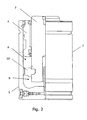
- the piston 10 divides the cylindrical chamber of the gas spring into a first space A between the piston 10 and the first end wall 2 and a second space B between the piston 10 and the second end wall 3 (see Fig. 2).
- piston halves 10a, 10b are separated by means of a gap 11, shown more clearly in Fig. 3.
- This gap 11 forms passages for gas to flow between the first and the second space.
- the piston halves are held together by a guide band 13, which constitutes a guide for the piston 10 in the tube 1.
- a gas spring is charged with a gas, which usually consists of nitrogen gas, to a pressure of up to 150 bar, for example.
- the gas is delivered to the cylindrical chamber via the valve 14 shown in the second end wall.
- One solution to these problems posed by the operating temperature of the gas spring is to make holes or recesses in the piston halves or the piston corresponding to a predefined gas through-flow area between the two spaces A and B, which permits a faster gas through-flow under the inward or outward movement of the piston/piston rod.
- a larger gas through-flow area results in a reduction of the pressure gradient between the two spaces A and B, in both the inward and the outward movement of the piston/piston rod, thereby reducing the amount of heat generated inside the gas spring.
- FIG. 4 A number of variants which specify alternative ways of bringing about an increase in the area of the through-flow passages are shown in Figs. 4 to 6.
- the area of the passages is increased by making a number of holes 15 around a circle concentric with the periphery of the piston.
- the gap 11 shown constitutes a part of the through-flow passages.
- a number of recesses 16 have been made in the peripheral surface of the piston 10.
- FIG. 6 Yet another variant is illustrated in Fig. 6, in which a pair of elongated holes 17 through the piston 10 extend along circular arcs concentric with the periphery of the piston.
- the through-flow passages may therefore consist, wholly or in part, of any type of cylindrical cavity that extends axially though the piston, and the cross-section of such a cavity may have any area.
- Fig. 7a shows a piston/piston rod combination of prior art and Fig. 7b in the lower figure shows a corresponding piston/piston rod combination according to a variant of the invention.
- the graphs in Fig. 8 show a first curve for the operating temperature increase over time for a conventional gas spring at a specific load and stroke rate.
- a second graph shows the corresponding curve for a gas spring according to one of the variants of the invention, in which the gas spring is designed with an area for the through-flow passages representing approximately 15% of the piston area.
Landscapes
- Engineering & Computer Science (AREA)
- General Engineering & Computer Science (AREA)
- Mechanical Engineering (AREA)
- Fluid-Damping Devices (AREA)
Description
- The present invention relates to a gas spring for a pressing tool, in which the design construction is improved in such a way that a lower operating temperature can be achieved at high loads.
- Gas springs have come to be widely used throughout industry. One example are pressing tools intended for forming sheet-metal parts in which gas springs are nowadays mainly used for the various spring functions that are required. Thus gas springs are used, for example, for securing sheet metal, returning shuttles and separating tool halves in the pressing process. Gas springs which support a blank holder for pressing sheet metal are loaded at the beginning of the pressing process and relieved by the upward movement of a press slide and/or a press upper part after sheet metal forming. The proportion of the stroke length of a gas spring that is subject to loading is governed by the pressing process and the ultimate appearance of the pressed sheet-metal part. In order to optimise the sheet metal forming operation full control over a pressing cycle is required. The speed of descent of the press upper part during sheet metal forming is often less than the speed of ascent of the press upper part after sheet metal forming.
- Since gas springs started to be used in pressing tools the production rate has increased markedly. The increased production rate has resulted in a faster pressing process with consequently higher press speeds and shorter rest time between the pressing cycles in order to maintain a high level of efficiency. In addition, longer production runs have resulted in increased pressing tool operating times, which has in turn placed greater demands on the types of presses currently used for sheet metal forming. These presses are able to cope with substantially higher pressing speeds than the presses available when the gas spring was first introduced in the sheet metal forming industry.
- A gas spring according to the prior art is shown in Fig. 1 and comprises a cylindrical chamber having a first wall formed by one of the base surfaces of the cylinder, and a second wall formed by the other base surface of the cylinder. A piston, which is capable of an axial reciprocating movement in the cylindrical chamber divides said chamber into a first space A between the piston and the first wall and a second space B between the piston and the second wall. The piston is fastened to a piston rod which is axially moveable in a piston rod guide in the first wall. The gas spring with its spring force is thereby capable of counteracting a movement produced by forces acting axially on the piston rod, in that the first space and the second space are pressurised by means of a gas, which flows, via passages connecting the first space and the second space, from the space subject to compression to the space that is subject to expansion under the axial movement of the piston rod. The gas in the piston therefore flows in a direction counter to the direction of movement of the piston. The piston is of annular design and is arranged around the piston rod.
- A gas spring functions briefly as follows. The two spaces are charged, to a pressure of 150 bar, for example, with a gas, generally nitrogen gas. The gas pressure acts on the piston and the piston rod, thereby producing a spring force acting on the piston rod when this is displaced. The area which gives a specific spring force for a specific gas pressure is therefore the cross-sectional area of the piston rod. In operation, the entire piston rod of the gas spring may be pressed in by a force that is applied to the piston rod, the nitrogen gas being compressed in the space into which the piston and the piston rod penetrate, whereupon the pressure in said space rises. The extent to which the pressure rises depends upon the pressure build-up of the gas spring (that is to say the configuration of the volumes of the cylinder, the piston and the spaces) and upon the operating temperature. Following a full piston rod stroke, it returns to the unloaded starting position, whereupon a new compression commences. This process is repeated throughout the life of the gas spring. Under compression the gas flows, for example, from the second space B to the first space A via a gap, which in gas springs known in the art occurs between two halves which together make up the piston. The sequence is naturally reversed when the piston moves in the opposite direction. In the current state of the art relating to gas springs, the area of the through-flow passages arranged in the piston, for example by means of the aforementioned gap between the piston halves, generally occupies from 2% to 3% of the area of the piston, the area of the piston here being defined as the difference between the cross-sectional areas of the cylindrical chamber and the piston rod.
- The ever faster pressing processes nowadays mean that the gas spring is subjected to increased loading as the movement of the piston inside the gas spring occurs more rapidly and more frequently, which in turn leads to the generation of more heat inside the gas spring so that the operating temperature of the gas spring increases.
- The temperature increase is most manifest on gas springs containing pistons designed rest against the inner wall of the tube.
- The stroke rate for a machine press is generally between approximately 0.3 and 2 strokes per second, a usual rate being approximately 1 stroke per second. The pressing speed of a machine press and hence the speed of the piston rod and piston of the gas spring during sheet metal forming is usually about 0.2 - 0.8 m/s. The return speed of the piston rod may reach 1.8 m/s. A machine press usually operates with pressing forces of about 5-600 tonnes (50-6000 kN), the forces to which each of the gas springs of the pressing tool is subjected usually being between approximately 2 kN and 150 kN. The stroke length of a gas spring in such a machine tool usually depends on the forming depth, that is to say the part of the stroke length of the pressing tool performing an operation such as forming sheet metal. A usual stroke length is approximately 100 to 160 mm, but a manufacturer's ordinary standard range usually covers anything from just a few millimetres up to 300-400 mm.
- Since most pressing tools are to be found in industries that operate under tight financial constraints, for example the motor vehicle industry in which the pressing tools are used to form sheet-metal parts for vehicle bodies, these pressing tools and hence also the gas springs of the pressing tools will commonly be used in shifts of approximately 2 to 4 hours, but even longer shifts occur of up to 8 or 12 hours, for example, with more than one shift per day, so that the operating time can in some cases approach 20-24 hours per day. Unscheduled stoppages of these pressing tools are very costly.
- As an example, one of the best selling gas springs for pressing tools, which delivers a force of 30 kN and has a stroke length of 125 mm, will be subjected to 1.1 strokes/s over a 4-hour shift, 4 times a day, that is to say 16 hours per day.
- Current requirements made of a gas spring for a pressing tool are generally that they should be capable of at least 1 million strokes or sometimes 2 million strokes without servicing. Another way of calculating the service life of a gas spring for a pressing tool is in stroke-metres, that is to say stroke length x 2 x number of strokes. An example of the service life of a gas spring for a pressing tool expressed in stroke metres is 100,000 or 200,000 stroke metres.
- When the pressing tool gas spring is charged, usually to 150 bar, and then put into operation, a pressure which may be significantly higher, for example 360 bar, is reached.
- For these reasons the manufacture and sale of gas springs for pressing tools involve a number of safety regulations and measures such as testing and pressure vessel approval.
- One of the causes of the heat generated inside the gas spring is the increase in pressure that occurs when the gas is compressed in one of the spaces A and B under the inward or outward movement of the piston in the cylinder, due to the piston restricting the gas flow during compression, with the result that a pressure gradient occurs between the two cylinder spaces A and B separated by the piston. The higher the pressing speed, the greater the pressure gradient that occurs. Another cause of the heat generated is friction inside the gas spring, for example in the gas movements, in the contact between seal and piston rod and in the contact between guide and piston rod during the inward and outward movement of the piston and the piston rod. The large amount of heat generated in the gas spring places greater stresses on existing seals, which can result in these being damaged and the gas spring ceasing to function.
- An object of the present invention is to reduce the pressure gradient that occurs between the two spaces in the gas spring when it is subjected to frequent long, rapid strokes.
- One aspect of the present invention describes a device in the form of the gas spring that is characterised by the independent device claim.
- A further aspect of the invention describes a method of reducing the pressure gradient that occurs between two pressurized spaces in a gas spring when the gas spring is subjected to spring forces according to the independent method claim.
- The advantage of the solution shown is that a reduced operating temperature is achieved, in that less heat is generated in the gas spring at high spring forces and high spring stroke frequency. This applies in particular in the case of long strokes or when a large proportion, for example 70-90%, of the maximum stroke length of the gas spring is used. This permits a faster pressing process when using the spring according to the invention in the pressing industry. The service life of the spring is also increased in that the stresses acting on seals are reduced due to the lower operating temperature.
- According to the aspect of the invention an area in the order of 10-15% of the piston area is preferably used for the through-flow passages. Good results in terms of a reduction in the operating temperature are also achieved for passage areas that exceed 7% of the piston area. An improvement is obtained just by increasing the passage area to 5%, but this is not ideal since the reduction in the operating temperature of the gas spring is insufficient. Each percentage point, 6, 7, 8, 9, 10, 11% etc. that the passage area is increased brings a reduction in the operating temperature for a given stroke rate and a given stroke length. If the passage area is increased to more than 25% each percentage point increase fails to bring as great a reduction in the operating temperature as for each percentage point increase in the passage area in the order of 10-15 %.
- The combination of increasing service life and safety requirements means that the cost of gas springs for pressing tools is relatively high. This makes it economic to repair the gas springs for pressing tools. The pressing tool gas spring according to the invention is therefore designed so that it can be easily dismantled and worn parts replaced before fitting the gas spring to the pressing tool again.
- When dismantling, the gas is first discharged via the
valve 14. Theguide 4 is then pressed in somewhat so that thelocking ring 6 can be removed. In this position thepiston 10, thepiston rod 7 and theguide 4 can be drawn out of thetube 1. Once out of thetube 1, theguide band 13, which holds thepiston halves piston rod 7 is dismantled. In this position on thepiston rod 7 there is an annular recess in the latter. The piston halves 10a, 10b are of a complementary shape to this recess, which means that when this shape is inserted into the annular recess it holds the piston halves axially in place. The piston halves 10a, 10b are therefore held radially in place by the guide band, which is in turn supported by the tube when it is inserted in the tube, and thepiston halves piston rod 7. Forming thepiston 10 from twopiston halves - The piston in the pressing tool gas spring according to the invention is of the guide-type, that is to say it is designed to rest against the inside of the tube and thereby to guide the end of the piston rod which is situated inside the pressing tool gas spring towards the centre of the tube. This means that the piston rod acquires a movement concentrically parallel with the tube and this therefore counteracts any skewing of the piston rod in relation to the guide. Skewing causes wearing of the piston rod and the contact surfaces of the guide, which has a detrimental effect on the service life of the pressing tool gas spring. Seals will also be obliquely loaded, thereby impairing the functioning of the pressing tool gas spring.
- A central feature of the invention is the reduction of said pressure gradient and of the operating temperature by increasing the area of the passages in which gas can flow from the first space to the second space in the gas spring. The area of the passages can be increased in several ways. This can be achieved by means of holes in the piston, recesses in the piston, larger gap width between piston halves, or by gaps between several piston parts. Other obvious ways include the arrangement of passages at the side of the piston, for example in the cylinder walls, outside the tube or in the piston rod, by means of so-called overflow ducts. With these further means the passage area may exceed 100%, according to the definition. In increasing the passage area simply by means of holes and/or recesses in the piston, the strength of the piston will probably preclude the passage area from exceeding approximately 70-95%.
-
- Fig. 1 shows an exploded schematic drawing of a gas spring of prior art, of the type encompassed by the invention.
- Fig. 2 shows a schematic drawing of partial section through a gas spring.
- Fig. 3 illustrates a piston according to the prior art in the form of two piston halves in which the through-flow passages comprise a gap between halves of the piston.
- Fig. 4 shows an alternative for increased through-flow area according to the invention.
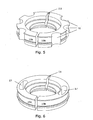
- Fig. 5 represents another alternative for increased through-flow area according to the invention.
- Fig. 6 represents a further alternative for increased through-flow area according to the invention.
- Fig. 7a shows an schematic drawing of a piston/piston rod combination according to the prior art, and Fig. 7b shows a corresponding alternative according to the invention.
- Fig. 8 shows graphs of the operating temperature for a gas spring of conventional design in the upper graph, whilst the lower graph shows the operating temperature curve for a gas spring according to the invention under equivalent loading.
- A number of embodiments of the invention are described below with reference to the drawings attached.
- Fig. 1 depicts a gas spring of conventional type. A
cylindrical tube 1 forms the cylindrical casing of the gas spring and thereby the wall of the cylindrical chamber of the gas spring. The cylindrical chamber is defined by two end walls, afirst end wall 2 and asecond end wall 3. In the embodiment shown theend wall 2 comprises apiston rod guide 4, which is inserted and sealed in relation to an open end of thetube 1 by means of astatic seal 5 and is furthermore locked against thetube 1 by means of alocking ring 6. Theother end wall 3 comprises a closed part firmly connected to thetube 1. Running in thepiston rod guide 4 is apiston rod 7, which is axially moveable along the axis of the cylindrical chamber and is supported so that it can slide in thepiston rod guide 4 and is sealed off against this by means of adynamic seal 8. Ascraper 9 on the outer part of the piston rod guide encloses the piston rod and keeps the piston rod free of oil and dirt. Apiston 10 is fitted to the inmost part of thepiston rod 7, in this case as twopiston halves piston rod 7. Thepiston 10 divides the cylindrical chamber of the gas spring into a first space A between thepiston 10 and thefirst end wall 2 and a second space B between thepiston 10 and the second end wall 3 (see Fig. 2). In the example thepiston halves gap 11, shown more clearly in Fig. 3. Thisgap 11 forms passages for gas to flow between the first and the second space. The piston halves are held together by aguide band 13, which constitutes a guide for thepiston 10 in thetube 1. - A gas spring is charged with a gas, which usually consists of nitrogen gas, to a pressure of up to 150 bar, for example. The gas is delivered to the cylindrical chamber via the
valve 14 shown in the second end wall. - In the event of a spring movement, which is produced by the application of a force to the outer part of the
piston rod 7, so that thepiston rod 7 is pressed inwards towards theend wall 3, the gas in the second space B is compressed. A counter-springing force on thepiston rod 7 is here created by the compressed gas. Gas can flow through the passages in the form of thegap 11 to the first space A. As previously stated, a pressure gradient occurs between the two spaces A and B when the piston moves in either direction. In the case of rapid piston movements, when the load is large and the stroke length represents a large proportion of the maximum stroke length of the gas spring, the pressure gradient may be large, with the result that the previously described increase in the operating temperature occurs. The through-flow passages are conventionally designed with an area which represents about 2% of the piston area. - One solution to these problems posed by the operating temperature of the gas spring is to make holes or recesses in the piston halves or the piston corresponding to a predefined gas through-flow area between the two spaces A and B, which permits a faster gas through-flow under the inward or outward movement of the piston/piston rod. A larger gas through-flow area results in a reduction of the pressure gradient between the two spaces A and B, in both the inward and the outward movement of the piston/piston rod, thereby reducing the amount of heat generated inside the gas spring.
- A number of variants which specify alternative ways of bringing about an increase in the area of the through-flow passages are shown in Figs. 4 to 6. In Fig. 4 the area of the passages is increased by making a number of
holes 15 around a circle concentric with the periphery of the piston. In the example shown thegap 11 shown constitutes a part of the through-flow passages. - According to another variant of the invention as shown in Fig. 5 a number of
recesses 16 have been made in the peripheral surface of thepiston 10. - Yet another variant is illustrated in Fig. 6, in which a pair of
elongated holes 17 through thepiston 10 extend along circular arcs concentric with the periphery of the piston. - There is obviously further scope for the design of the through-flow passages. The essential point is to achieve the desired increase in the gas through-flow area.
- The through-flow passages may therefore consist, wholly or in part, of any type of cylindrical cavity that extends axially though the piston, and the cross-section of such a cavity may have any area.
- Fig. 7a shows a piston/piston rod combination of prior art and Fig. 7b in the lower figure shows a corresponding piston/piston rod combination according to a variant of the invention.
- The graphs in Fig. 8 show a first curve for the operating temperature increase over time for a conventional gas spring at a specific load and stroke rate. A second graph shows the corresponding curve for a gas spring according to one of the variants of the invention, in which the gas spring is designed with an area for the through-flow passages representing approximately 15% of the piston area.
Claims (10)
- Gas spring for a pressing tool comprising a tube (1) which forms a wall of a cylindrical chamber having a first end wall (2), which constitutes a first base surface and a second end wall (3) which constitutes a second base surface of the cylindrical chamber, in which a piston (10), which is designed to rest against the tube (1), is capable of reciprocating axially in the cylindrical chamber and divides said chamber into a first space (A) between the piston (10) and the first end wall (2) and a second space (B) between the piston (10) and the second end wall (3), and in which the piston (10) is attached to a piston rod (7), which is axially moveable and supported so that it can slide in a piston rod guide (4) at the first end wall (2), and the piston (10) has passages (11, 15, 16, 17) which connect the first space (A) and the second space (B), the passages (11, 15, 16, 17) permitting a flow of gas from the space that is subject to compression to the space that is subject to expansion under the axial movement of the piston rod (7), the gas spring with an opposing force counteracting a movement that is produced by forces acting axially on the piston rod (7) in that the first space (A) and the second space (B) are pressurised by means of a gas, characterised in that the passages (11, 15, 16, 17) which permit the flow of gas between the first space (A) and the second space (B) occupy an area which is greater than 5% of the area of the piston (10), the area of the piston being the difference between the cross-sectional areas of the cylindrical chamber and the piston rod, in order to reduce the amount of heat generated in the gas spring.
- Gas spring according to Claim 1, characterised in that the total area of the passages (11, 15, 16, 17) is greater than 7% of the area of the piston (10).
- Gas spring according to Claim 1, characterised in that the total area of the passages (11, 15, 16, 17) represents between 5% and 25% of the area of the piston.
- Gas spring according to Claim 2, characterised in that the total area of the passages (11, 15, 16, 17) represents between 7% and 70% of the area of the piston.
- Gas spring according to any one of Claims 1 to 4, characterised in that the passages partially comprise a multiplicity of apertures (15) extending axially right through the piston (10)
- Gas spring according to any one of Claims 1 to 4, characterised in that the passages partially comprise cavities (15, 16, 17) formed from any type of cylindrically shaped space and extending axially right through the piston (10).
- Gas spring according to any one of Claims 1 to 4, characterised in that the passages partially comprise cavities in the form of recesses (16) in the peripheral surface of the piston and extending axially right through the piston (10).
- Gas spring according to any one of Claims 1 to 4, characterised in that the passages comprise gaps between a plurality of piston parts which together form the piston (10).
- Gas spring according to any one of Claims 1 to 4, characterised in that the passages partially comprise connections connecting the first space (A) and the second space (B) to one another at the side of the annular piston (10).
- Method of reducing a pressure gradient that occurs between a first space (A) and a second space (B) in a pressing tool gas spring which comprises:
a tube (1) which forms a wall of a cylindrical chamber having a first end wall (2), which constitutes a first base surface and a second end wall (3) which constitutes a second base surface of the cylindrical chamber and in which a piston (10) is capable of reciprocating axially in the cylindrical chamber, the first space (A) comprising a chamber which is formed between the piston (10) and the first end wall (2) and the second space (B) comprising a chamber which is formed between the piston (10) and the second end wall (3), and in which the piston (10) is attached to a piston rod (7), which is axially moveable and supported so that it can slide in a piston rod guide (4) at the first end wall (2), the gas spring with an opposing force counteracting a movement that is produced by forces acting axially on the piston rod (7) in that the first space (A) and the second space (B) are pressurised by means of a gas, the first space (A) and the second space (B) being connected by way of passages (11, 15, 16, 17) and gas flowing via said passages from the space that is subject to compression to the space that is subject to expansion under the axial movement of the piston rod (7), the method being characterised in that said passages (11, 15, 16, 17) which connect the first space (A) to the second space (B) are provided with a total cross-sectional area which represents at least 5% of the area of the piston (10), the piston area being regarded as the difference between the cross-sectional areas of the cylindrical chamber and the piston rod.
Applications Claiming Priority (2)
| Application Number | Priority Date | Filing Date | Title |
|---|---|---|---|
| SE0301095A SE524879C2 (en) | 2003-04-11 | 2003-04-11 | Gas spring |
| PCT/SE2004/000528 WO2004090370A1 (en) | 2003-04-11 | 2004-04-05 | Gas spring |
Publications (2)
| Publication Number | Publication Date |
|---|---|
| EP1613874A1 EP1613874A1 (en) | 2006-01-11 |
| EP1613874B1 true EP1613874B1 (en) | 2006-12-20 |
Family
ID=20291021
Family Applications (1)
| Application Number | Title | Priority Date | Filing Date |
|---|---|---|---|
| EP04725851A Expired - Lifetime EP1613874B1 (en) | 2003-04-11 | 2004-04-05 | Gas spring |
Country Status (8)
| Country | Link |
|---|---|
| US (1) | US7278632B2 (en) |
| EP (1) | EP1613874B1 (en) |
| JP (1) | JP4637094B2 (en) |
| KR (1) | KR100853572B1 (en) |
| DE (1) | DE602004003805T2 (en) |
| ES (1) | ES2278311T3 (en) |
| SE (1) | SE524879C2 (en) |
| WO (1) | WO2004090370A1 (en) |
Families Citing this family (6)
| Publication number | Priority date | Publication date | Assignee | Title |
|---|---|---|---|---|
| JP2008157343A (en) * | 2006-12-22 | 2008-07-10 | Pascal Engineering Corp | gas spring |
| GB2464350B (en) * | 2008-10-17 | 2013-07-17 | Linval Rodney | Nitrogen gas spring |
| KR101137998B1 (en) * | 2010-01-04 | 2012-04-20 | (주)베스텍 | gas spring |
| US9145944B2 (en) * | 2010-02-10 | 2015-09-29 | Alberto Bordignon | Gas spring equipped with improved sealing means |
| US10072723B2 (en) * | 2015-04-24 | 2018-09-11 | Beijingwest Industries Co., Ltd. | Closing assembly for a magneto-rheological damper |
| CN113124081A (en) * | 2021-04-25 | 2021-07-16 | 深圳市大通精密五金有限公司 | Novel nitrogen spring |
Family Cites Families (21)
| Publication number | Priority date | Publication date | Assignee | Title |
|---|---|---|---|---|
| FR359201A (en) | 1905-11-07 | 1906-03-19 | Claudius Gros | Progressive action shock absorber for all types of suspension |
| FR686705A (en) | 1928-12-17 | 1930-07-30 | Brisset Et Sanua Ets | Improvements made to processes to make cement concrete surfaces waterproof and unassailable against chemical agents |
| FR995019A (en) * | 1949-07-15 | 1951-11-26 | Improvements to direct-acting hydraulic suspension shocks | |
| DE1134253B (en) | 1960-10-10 | 1962-08-02 | Goetzewerke | Elastic piston for vibration damper |
| FR2425018A1 (en) | 1978-05-05 | 1979-11-30 | Bourcier Carbon Christian | IMPROVEMENT IN PISTONS FOR SHOCK ABSORBERS |
| US4775038A (en) * | 1986-10-30 | 1988-10-04 | Maremont Corporation | Spring loaded piston seal and valving component for shock absorbers, Macpherson struts and the like |
| JPH0442594Y2 (en) * | 1987-03-20 | 1992-10-08 | ||
| JPH0227043U (en) * | 1988-08-09 | 1990-02-22 | ||
| JPH0231930U (en) * | 1988-08-23 | 1990-02-28 | ||
| DE3935159A1 (en) | 1989-10-21 | 1991-04-25 | Boge Ag | Piston for hydraulic telescopic vibration damper - has two parts each with group of ducts, with valve shaped disc section and piston parts |
| US5070971A (en) | 1990-04-23 | 1991-12-10 | General Motors Corporation | Molded piston for a hydraulic damper |
| JPH08145103A (en) * | 1994-11-18 | 1996-06-04 | Tokico Ltd | gas spring |
| FR2742505B1 (en) | 1995-12-13 | 1998-11-27 | Jean Perret Ets | DAMPER |
| JPH09269030A (en) | 1996-03-29 | 1997-10-14 | Showa:Kk | Support device for lids, etc. |
| KR19980067963U (en) * | 1997-05-30 | 1998-12-05 | 오상수 | Gas springs with improved damping |
| US6102170A (en) * | 1998-05-07 | 2000-08-15 | Tenneco Automotive Inc. | Passive anti-roll system |
| US6199671B1 (en) * | 1998-09-14 | 2001-03-13 | New Joules Engineering (Sales) Proprietary) Limited | Shock absorber |
| DE10115980C2 (en) | 2001-03-30 | 2003-04-10 | Pnp Luftfedersysteme Gmbh | Gas spring damper unit for a motor vehicle |
| JP4055060B2 (en) * | 2002-09-30 | 2008-03-05 | 株式会社日立製作所 | Hydraulic shock absorber |
| KR200309685Y1 (en) * | 2002-12-30 | 2003-04-03 | 주식회사 썬 프레인 코 | The valve for gas spring |
| US7070029B2 (en) * | 2003-09-15 | 2006-07-04 | Tenneco Automotive Operating Company Inc. | Monotube piston valving system with selective bleed |
-
2003
- 2003-04-11 SE SE0301095A patent/SE524879C2/en not_active IP Right Cessation
-
2004
- 2004-04-05 WO PCT/SE2004/000528 patent/WO2004090370A1/en not_active Ceased
- 2004-04-05 ES ES04725851T patent/ES2278311T3/en not_active Expired - Lifetime
- 2004-04-05 US US10/536,985 patent/US7278632B2/en not_active Expired - Lifetime
- 2004-04-05 KR KR1020057014426A patent/KR100853572B1/en not_active Expired - Lifetime
- 2004-04-05 EP EP04725851A patent/EP1613874B1/en not_active Expired - Lifetime
- 2004-04-05 DE DE602004003805T patent/DE602004003805T2/en not_active Expired - Lifetime
- 2004-04-05 JP JP2006508003A patent/JP4637094B2/en not_active Expired - Lifetime
Also Published As
| Publication number | Publication date |
|---|---|
| JP2006522908A (en) | 2006-10-05 |
| SE524879C2 (en) | 2004-10-19 |
| US20060096819A1 (en) | 2006-05-11 |
| KR20050123095A (en) | 2005-12-29 |
| WO2004090370A1 (en) | 2004-10-21 |
| ES2278311T3 (en) | 2007-08-01 |
| SE0301095D0 (en) | 2003-04-11 |
| KR100853572B1 (en) | 2008-08-21 |
| EP1613874A1 (en) | 2006-01-11 |
| SE0301095L (en) | 2004-10-12 |
| JP4637094B2 (en) | 2011-02-23 |
| DE602004003805T2 (en) | 2007-10-11 |
| DE602004003805D1 (en) | 2007-02-01 |
| US7278632B2 (en) | 2007-10-09 |
Similar Documents
| Publication | Publication Date | Title |
|---|---|---|
| US6026777A (en) | Piston having a barrel of forged steel and a cooling channel | |
| CN103291801B (en) | The gentle spring members of air spring | |
| US5176229A (en) | Hydraulic shock absorber with a rod guide having an annular doubled wall section | |
| US3994208A (en) | Piston for high-pressure hydraulic machine | |
| EP2857711B1 (en) | Overtravel pressure relief for a gas spring | |
| US6540052B2 (en) | Damping valve, in particular for a vibration damper | |
| EP3408521B1 (en) | Crankcase assembly for a reciprocating machine | |
| US6659243B2 (en) | Shaft seat part structure of hydraulic shock absorber and assembling method thereof | |
| KR20160033712A (en) | Sealing device for piston | |
| US6591948B2 (en) | Piston with support webs for a piston-cylinder arrangement, in particular a shock absorber piston | |
| US7278632B2 (en) | Gas spring | |
| EP0491942B1 (en) | Annular support for a seal for a tilt piston | |
| JP2006500541A (en) | Piston body manufactured by powder metallurgy with a support abdomen and method for manufacturing the same | |
| US7559542B2 (en) | Low impact gas spring | |
| US7178237B2 (en) | Piston for a piston-cylinder arrangement, in particular a shock absorber piston | |
| KR102405027B1 (en) | Relief of overtravel pressure of gas spring | |
| US8104771B2 (en) | Oil-control ring for an internal combustion engine | |
| JPH0517993B2 (en) | ||
| US9890773B2 (en) | Wobble piston having angled compression ring and spherical piston cap | |
| US7395838B2 (en) | Piston-type accumulator | |
| EP0502445B1 (en) | A container rod assembly | |
| WO2006112942A2 (en) | Gas spring and method of manufacture | |
| US5794517A (en) | Piston assembly | |
| US5655634A (en) | Shock absorbers and vibration dampers; and shock absorbers and vibration dampers with a piston with a piston ring; and a cyclinder with a piston with a piston ring | |
| JP4588949B2 (en) | Seal mechanism and seal member therefor |
Legal Events
| Date | Code | Title | Description |
|---|---|---|---|
| PUAI | Public reference made under article 153(3) epc to a published international application that has entered the european phase |
Free format text: ORIGINAL CODE: 0009012 |
|
| 17P | Request for examination filed |
Effective date: 20050609 |
|
| AK | Designated contracting states |
Kind code of ref document: A1 Designated state(s): AT BE BG CH CY CZ DE DK EE ES FI FR GB GR HU IE IT LI LU MC NL PL PT RO SE SI SK TR |
|
| AX | Request for extension of the european patent |
Extension state: AL HR LT LV MK |
|
| DAX | Request for extension of the european patent (deleted) | ||
| RBV | Designated contracting states (corrected) |
Designated state(s): DE ES FR GB |
|
| GRAP | Despatch of communication of intention to grant a patent |
Free format text: ORIGINAL CODE: EPIDOSNIGR1 |
|
| GRAS | Grant fee paid |
Free format text: ORIGINAL CODE: EPIDOSNIGR3 |
|
| GRAA | (expected) grant |
Free format text: ORIGINAL CODE: 0009210 |
|
| AK | Designated contracting states |
Kind code of ref document: B1 Designated state(s): DE ES FR GB |
|
| REG | Reference to a national code |
Ref country code: GB Ref legal event code: FG4D |
|
| REF | Corresponds to: |
Ref document number: 602004003805 Country of ref document: DE Date of ref document: 20070201 Kind code of ref document: P |
|
| ET | Fr: translation filed | ||
| REG | Reference to a national code |
Ref country code: ES Ref legal event code: FG2A Ref document number: 2278311 Country of ref document: ES Kind code of ref document: T3 |
|
| PLBE | No opposition filed within time limit |
Free format text: ORIGINAL CODE: 0009261 |
|
| STAA | Information on the status of an ep patent application or granted ep patent |
Free format text: STATUS: NO OPPOSITION FILED WITHIN TIME LIMIT |
|
| 26N | No opposition filed |
Effective date: 20070921 |
|
| REG | Reference to a national code |
Ref country code: FR Ref legal event code: PLFP Year of fee payment: 13 |
|
| REG | Reference to a national code |
Ref country code: FR Ref legal event code: PLFP Year of fee payment: 14 |
|
| REG | Reference to a national code |
Ref country code: FR Ref legal event code: PLFP Year of fee payment: 15 |
|
| PGFP | Annual fee paid to national office [announced via postgrant information from national office to epo] |
Ref country code: FR Payment date: 20230316 Year of fee payment: 20 |
|
| PGFP | Annual fee paid to national office [announced via postgrant information from national office to epo] |
Ref country code: GB Payment date: 20230316 Year of fee payment: 20 |
|
| P01 | Opt-out of the competence of the unified patent court (upc) registered |
Effective date: 20230517 |
|
| PGFP | Annual fee paid to national office [announced via postgrant information from national office to epo] |
Ref country code: ES Payment date: 20230503 Year of fee payment: 20 Ref country code: DE Payment date: 20230317 Year of fee payment: 20 |
|
| REG | Reference to a national code |
Ref country code: DE Ref legal event code: R071 Ref document number: 602004003805 Country of ref document: DE |
|
| REG | Reference to a national code |
Ref country code: GB Ref legal event code: PE20 Expiry date: 20240404 |
|
| PG25 | Lapsed in a contracting state [announced via postgrant information from national office to epo] |
Ref country code: ES Free format text: LAPSE BECAUSE OF EXPIRATION OF PROTECTION Effective date: 20240406 |
|
| REG | Reference to a national code |
Ref country code: ES Ref legal event code: FD2A Effective date: 20240426 |
|
| PG25 | Lapsed in a contracting state [announced via postgrant information from national office to epo] |
Ref country code: ES Free format text: LAPSE BECAUSE OF EXPIRATION OF PROTECTION Effective date: 20240406 |
|
| PG25 | Lapsed in a contracting state [announced via postgrant information from national office to epo] |
Ref country code: GB Free format text: LAPSE BECAUSE OF EXPIRATION OF PROTECTION Effective date: 20240404 |
|
| PG25 | Lapsed in a contracting state [announced via postgrant information from national office to epo] |
Ref country code: GB Free format text: LAPSE BECAUSE OF EXPIRATION OF PROTECTION Effective date: 20240404 |