EP1612909B1 - Power supply integrated circuit with feedback control - Google Patents
Power supply integrated circuit with feedback control Download PDFInfo
- Publication number
- EP1612909B1 EP1612909B1 EP05013692A EP05013692A EP1612909B1 EP 1612909 B1 EP1612909 B1 EP 1612909B1 EP 05013692 A EP05013692 A EP 05013692A EP 05013692 A EP05013692 A EP 05013692A EP 1612909 B1 EP1612909 B1 EP 1612909B1
- Authority
- EP
- European Patent Office
- Prior art keywords
- power
- power supply
- electrical
- supply information
- integrated circuit
- Prior art date
- Legal status (The legal status is an assumption and is not a legal conclusion. Google has not performed a legal analysis and makes no representation as to the accuracy of the status listed.)
- Active
Links
Images
Classifications
-
- G—PHYSICS
- G05—CONTROLLING; REGULATING
- G05F—SYSTEMS FOR REGULATING ELECTRIC OR MAGNETIC VARIABLES
- G05F1/00—Automatic systems in which deviations of an electric quantity from one or more predetermined values are detected at the output of the system and fed back to a device within the system to restore the detected quantity to its predetermined value or values, i.e. retroactive systems
- G05F1/66—Regulating electric power
-
- G—PHYSICS
- G05—CONTROLLING; REGULATING
- G05B—CONTROL OR REGULATING SYSTEMS IN GENERAL; FUNCTIONAL ELEMENTS OF SUCH SYSTEMS; MONITORING OR TESTING ARRANGEMENTS FOR SUCH SYSTEMS OR ELEMENTS
- G05B15/00—Systems controlled by a computer
- G05B15/02—Systems controlled by a computer electric
-
- H—ELECTRICITY
- H02—GENERATION; CONVERSION OR DISTRIBUTION OF ELECTRIC POWER
- H02J—CIRCUIT ARRANGEMENTS OR SYSTEMS FOR SUPPLYING OR DISTRIBUTING ELECTRIC POWER; SYSTEMS FOR STORING ELECTRIC ENERGY
- H02J1/00—Circuit arrangements for dc mains or dc distribution networks
- H02J1/06—Two-wire systems
-
- H—ELECTRICITY
- H02—GENERATION; CONVERSION OR DISTRIBUTION OF ELECTRIC POWER
- H02J—CIRCUIT ARRANGEMENTS OR SYSTEMS FOR SUPPLYING OR DISTRIBUTING ELECTRIC POWER; SYSTEMS FOR STORING ELECTRIC ENERGY
- H02J13/00—Circuit arrangements for providing remote indication of network conditions, e.g. an instantaneous record of the open or closed condition of each circuitbreaker in the network; Circuit arrangements for providing remote control of switching means in a power distribution network, e.g. switching in and out of current consumers by using a pulse code signal carried by the network
- H02J13/00002—Circuit arrangements for providing remote indication of network conditions, e.g. an instantaneous record of the open or closed condition of each circuitbreaker in the network; Circuit arrangements for providing remote control of switching means in a power distribution network, e.g. switching in and out of current consumers by using a pulse code signal carried by the network characterised by monitoring
-
- Y—GENERAL TAGGING OF NEW TECHNOLOGICAL DEVELOPMENTS; GENERAL TAGGING OF CROSS-SECTIONAL TECHNOLOGIES SPANNING OVER SEVERAL SECTIONS OF THE IPC; TECHNICAL SUBJECTS COVERED BY FORMER USPC CROSS-REFERENCE ART COLLECTIONS [XRACs] AND DIGESTS
- Y02—TECHNOLOGIES OR APPLICATIONS FOR MITIGATION OR ADAPTATION AGAINST CLIMATE CHANGE
- Y02B—CLIMATE CHANGE MITIGATION TECHNOLOGIES RELATED TO BUILDINGS, e.g. HOUSING, HOUSE APPLIANCES OR RELATED END-USER APPLICATIONS
- Y02B90/00—Enabling technologies or technologies with a potential or indirect contribution to GHG emissions mitigation
- Y02B90/20—Smart grids as enabling technology in buildings sector
-
- Y—GENERAL TAGGING OF NEW TECHNOLOGICAL DEVELOPMENTS; GENERAL TAGGING OF CROSS-SECTIONAL TECHNOLOGIES SPANNING OVER SEVERAL SECTIONS OF THE IPC; TECHNICAL SUBJECTS COVERED BY FORMER USPC CROSS-REFERENCE ART COLLECTIONS [XRACs] AND DIGESTS
- Y02—TECHNOLOGIES OR APPLICATIONS FOR MITIGATION OR ADAPTATION AGAINST CLIMATE CHANGE
- Y02E—REDUCTION OF GREENHOUSE GAS [GHG] EMISSIONS, RELATED TO ENERGY GENERATION, TRANSMISSION OR DISTRIBUTION
- Y02E60/00—Enabling technologies; Technologies with a potential or indirect contribution to GHG emissions mitigation
-
- Y—GENERAL TAGGING OF NEW TECHNOLOGICAL DEVELOPMENTS; GENERAL TAGGING OF CROSS-SECTIONAL TECHNOLOGIES SPANNING OVER SEVERAL SECTIONS OF THE IPC; TECHNICAL SUBJECTS COVERED BY FORMER USPC CROSS-REFERENCE ART COLLECTIONS [XRACs] AND DIGESTS
- Y04—INFORMATION OR COMMUNICATION TECHNOLOGIES HAVING AN IMPACT ON OTHER TECHNOLOGY AREAS
- Y04S—SYSTEMS INTEGRATING TECHNOLOGIES RELATED TO POWER NETWORK OPERATION, COMMUNICATION OR INFORMATION TECHNOLOGIES FOR IMPROVING THE ELECTRICAL POWER GENERATION, TRANSMISSION, DISTRIBUTION, MANAGEMENT OR USAGE, i.e. SMART GRIDS
- Y04S10/00—Systems supporting electrical power generation, transmission or distribution
- Y04S10/30—State monitoring, e.g. fault, temperature monitoring, insulator monitoring, corona discharge
-
- Y—GENERAL TAGGING OF NEW TECHNOLOGICAL DEVELOPMENTS; GENERAL TAGGING OF CROSS-SECTIONAL TECHNOLOGIES SPANNING OVER SEVERAL SECTIONS OF THE IPC; TECHNICAL SUBJECTS COVERED BY FORMER USPC CROSS-REFERENCE ART COLLECTIONS [XRACs] AND DIGESTS
- Y04—INFORMATION OR COMMUNICATION TECHNOLOGIES HAVING AN IMPACT ON OTHER TECHNOLOGY AREAS
- Y04S—SYSTEMS INTEGRATING TECHNOLOGIES RELATED TO POWER NETWORK OPERATION, COMMUNICATION OR INFORMATION TECHNOLOGIES FOR IMPROVING THE ELECTRICAL POWER GENERATION, TRANSMISSION, DISTRIBUTION, MANAGEMENT OR USAGE, i.e. SMART GRIDS
- Y04S20/00—Management or operation of end-user stationary applications or the last stages of power distribution; Controlling, monitoring or operating thereof
Description
- Different electrical circuits and/or devices may be designed to operate using electrical power having a variety of characteristics. Even electrical circuits and/or devices designed to receive electrical power at an identical voltage level may have different power supply needs. For example, some circuits or devices may operate well over a larger voltage range than others. Also for example, some circuits or devices may operate better under noisy conditions than other circuits. Even a particular electrical circuit or device may utilize electrical power differently and have different power needs at various points in time. For example, the amount of electrical energy consumed in a circuit or device may vary in accordance with varying utilization of various circuit components or sub-components.
- Characteristics of electrical power supplied to electrical circuits, or components thereof may vary over time. For example, the power supply providing the electrical power may exhibit inconsistent behavior. Further for example, the consumption of energy by one or more circuit components may affect characteristics of electrical power provided to other components. For example an increased utilization of current by a first electrical component may result in a voltage and/or current decrease to a second electrical device.
- Because of varying power supply needs (e.g., between circuits and during operation) and varying power supply characteristics, electrical circuits or components thereof are often forced to operate with power supply characteristics that are less than desirable.
- Further limitations and disadvantages of conventional and traditional approaches will become apparent to one of skill in the art, through comparison of such systems with the present invention as set forth in the remainder of the present application with reference to the drawings.
-
US 2004/123164 A1 D1 discloses a power control system for controlling and monitoring POL regulators within a distributed power system. To achieve this, according to D1, a power control system is provided which comprises a plurality of POL regulators, and a system controller connected to the serial data bus and adapted to send and receive digital data to and from the plurality of POL regulators. The serial data bus further comprises a first data bus carrying programming and control information between the system controller and the plurality of POL regulators. The serial data bus may also include a second data bus carrying fault management information between the system controller and the plurality of POL regulators. The power control may also include a front-end regulator providing an intermediate voltage to the plurality of POL regulators on an intermediate voltage bus. - Anonymous: "Integrated Voltage Regulator for an On-Card +1.7 Volt Power Supply" IBM TECHNICAL DISCLOSURE BULLETIN, IBM CORP. NEW YORK, US, vol. 31, no. 2, 1 July 1988, pp. 22 to 23, XP002344799 shows an integrated voltage regulator for an on-card +1.7 Volt power supply. In particular, a voltage regulator circuit that is integrated within a logic masterslice is described, according to which the need for a discrete regulator for the above mentioned power supply is eliminated. The integrated voltage regulator circuit provides a regulated +1.7 volt source by controlling the base current of an off-chip Darlington transistor whose collector is connected to a +0.5 Volt power supply and whose emitter drives the +1.7 Volt bus.
- According to the present invention, a power management integrated circuit having the features according to claim 1 and a method having the features of claim 8 art provided. Preferred embodiments are defined in the respective dependent claims.
- Various aspects of the present invention provide a system and method for providing power control in a power management integrated circuit, substantially as shown in and/or described in connection with at least one of the figures, as set forth more completely in the claims. These and other advantages, aspects and novel features of the present invention, as well as details of illustrative aspects thereof, will be more fully understood from the following description and drawings.
- According to an aspect of the invention, a power management integrated circuit is provided comprising:
- a communication interface module adapted to receive power supply information from at least one electrical device, wherein the power supply information comprises information related to a first electrical power; and
- a power regulator module adapted to:
- determine a regulated power signal based at least in part on a portion of the power supply information, wherein the regulated power signal corresponds to the first electrical power; and
- output the regulated power signal to at least one electrical device.
- Advantageously, the power regulator module is adapted to determine a regulated power signal by determining one or more characteristic(s) of the first electrical power based at least in part on a portion of the power supply information, wherein the regulated power signal corresponds to the first electrical power characterized by the determined characteristic(s). Advantageously, the power supply information comprises information related to voltage level of the first electrical power. Advantageously, the communication interface module comprises a digital signal interface, and the power supply information comprises digital information related to the first electrical power.
- Advantageously, the regulated power signal comprises the first electrical power.
- Advantageously, the regulated power signal causes power supply circuitry external to the integrated circuit to output the first electrical power.
Advantageously, the at least one electrical device to which the power regulator module outputs the regulated power signal comprises power supply circuitry.
Advantageously, the at least one electrical device to which the power regulator module outputs the regulated power signal comprises the at least one electrical device from which the communication interface module receives the power supply information.
Advantageously, the at least one electrical device from which the communication interface module receives the power supply information utilizes the first electrical power.
Advantageously, the power supply information comprises information related to a second electrical power, and further comprising a second power regulator module adapted to: - determine a second regulated power signal based at least in part on a portion of the power supply information, wherein the second regulated power signal corresponds to the second electrical power; and
- output the second regulated power signal to at least one electrical device external to the power management integrated circuit.
- a communication interface module adapted to receive power supply information from at least one electrical device external to the power management integrated circuit, wherein the power supply information comprises information related to a first electrical power;
- a regulator control module adapted to process the received power supply information and generate a first regulator control signal based, at least in part, on the received power supply information; and
- a power regulator module adapted to:
- determine a regulated power signal based at least in part on the first regulator control signal, wherein the regulated power signal corresponds to the first electrical power; and
- output the regulated power signal to at least one electrical device external to the power management integrated circuit.
- determining one or more characteristics of the first electrical power based at least in part on a portion of the power supply information; and
- determining the first regulator control signal based, at least in part, on the determined characteristic(s) of the first electrical power;
- wherein the regulated power signal output by the power regulator module corresponds to the first electrical power characterized by the determined characteristic(s).
- the power supply information comprises information related to a second electrical power; and
- the regulator control module is adapted to process the received power supply information and generate a second regulator control signal based at least in part on the received power supply information; and
- further comprising a second power regulator module adapted to:
- determine a second regulated power signal based at least in part on the second regulator control signal, wherein the second regulated power signal corresponds to the second electrical power; and
- output the second regulated power signal to at least one electrical device external to the power management integrated circuit.
- receiving power supply information from at least one electrical device external to the integrated circuit, wherein the power supply information comprises information related to a first electrical power;
- determining a regulated power signal based at least in part on a portion of the power supply information, wherein the regulated power signal corresponds to the first electrical power; and
- outputting the regulated power signal to at least one electrical device external to the integrated circuit.
- determining a second regulated power signal based at least in part on a portion of the power supply information, wherein the second regulated power signal corresponds to the second electrical power; and
- outputting the second regulated power signal to at least one electrical device external to the integrated circuit.
- receiving power supply information comprises receiving power supply information from a plurality of electrical devices external to the power management integrated circuit; and
- determining a regulated power signal comprises arbitrating between respective power supply needs of the plurality of electrical devices.
-
Figure 1 shows a block diagram of a system comprising an exemplary power management integrated circuit utilizing received power supply information, in accordance with various aspects of the present invention. -
Figure 2 shows a block diagram of a system comprising an exemplary power management integrated circuit utilizing received power supply information, in accordance with various aspects of the present invention. -
Figure 3 illustrates a flow diagram of a method for providing regulated signal(s) corresponding to electrical power(s) from a power management integrated circuit utilizing received power supply information, in accordance with various aspects of the present invention. -
Figure 4 illustrates a flow diagram of a method for providing regulated signal(s) corresponding to electrical power(s) from a power management integrated circuit utilizing power supply information received from a plurality of sources, in accordance with various aspects of the present invention. -
Figure 1 shows a block diagram of asystem 100 comprising an exemplary power management integratedcircuit 110 utilizing received power supply information, in accordance with various aspects of the present invention. The power management integratedcircuit 110 may comprise any of a variety of general integrated circuit characteristics. The power management integratedcircuit 110 may also comprise various aspects of known power regulation or generation circuitry. The power management integratedcircuit 110 may also comprise various aspects of circuitry that is not related to power regulation or generation. Accordingly, the scope of various aspects of the present invention should not be limited by characteristics of particular integrated circuitry, particular power regulation or generation circuitry, or particular circuitry that is not related to power regulation or generation. - The following discussion may generally refer to one or more "modules" that perform various functions. It should be noted that a "module" may be implemented in hardware, software or a combination thereof. Further, portions of modules may be shared. For example, a first module may share various hardware and/or software components with a second module. Accordingly, the scope of various aspects of the present invention should not be limited by characteristics of a specific implementation of a module or by arbitrary boundaries between modules.
- The exemplary power management integrated
circuit 110 may comprise acommunication interface module 120. Thecommunication interface module 120 may receivepower supply information 107 from at least oneelectrical device 105 external to theintegrated circuit 110. Also, for example, thecommunication interface module 120 may receivepower supply information 109 from at least oneelectrical device 108 internal to theintegrated circuit 110. Though the following discussion will generally discuss an exemplary scenario including an electrical device external to theintegrated circuit 110, the scope of various aspects of the present invention should by no means be limited by such externality. - Such
power supply information 107 may, for example, comprise information related to a first electrical power. Suchpower supply information 107 may, for example, also comprise information related to a second electrical power and/or nth electrical power. - The external electrical device(s) 105 may, for example, receive and utilize the first electrical power. Alternatively, for example, the external electrical device(s) 105 may communicate
power supply information 107 that originates at other electrical devices that utilize the first electrical power. Similarly, in an exemplary scenario involving a second or nth electrical power, the external electrical device(s) 105 may, for example, receive and utilize the second or nth electrical power. Alternatively, in an exemplary scenario, the external electrical device(s) 105 may communicatepower supply information 107 that originates at other electrical devices that utilize the second or nth electrical power. Further for example, the external electrical device(s) 105 may comprise one or more devices that monitor power supply characteristics. - The external electrical device(s) 105 may comprise characteristics of any of a large variety of electrical devices. For example and without limitation, the external electrical device(s) 105 may comprise characteristics of analog and/or digital circuitry. The external electrical device(s) 105 may, for example, comprise passive or active components. The external electrical device(s) 105 may, for example, comprise an integrated circuit. Further for example, the external device(s) 105 may comprise characteristics of processing circuitry, communication circuitry, control circuitry, user interface circuitry, etc. Accordingly, the scope of various aspects of the present invention should not be limited by characteristics of particular external electrical devices.
- The
power supply information 107 received by thecommunication interface module 120 may comprise characteristics of any of a variety of power supply information. For example and without limitation, thepower supply information 107 may comprise information related to power supply voltage level (e.g., voltage level of power received by a device or desired voltage level for power received by a device). Also for example, thepower supply information 107 may comprise information of any of a variety of characteristics of electrical power. Such characteristics may, for example and without limitation, comprise voltage variability characteristics (e.g., ripple, noise, stability, switching frequency, etc.), load response characteristics, various current-related power characteristics, energy-efficiency characteristics, etc. Suchpower supply information 107 may, for example, comprise absolute or relative values. Also, thepower supply information 107 may comprise general data communication information (e.g., source and/or destination information). The scope of various aspects of the present invention should not be limited by any particular power characteristics. - The
power supply information 107 may, for example, comprise analog and/or digital information. Accordingly, thecommunication interface module 120 may comprise analog and/or digital communication capability. In an exemplary scenario, thepower supply information 107 may comprise power supply information of a single power supply characteristic (e.g., voltage) represented by a voltage level on a single wire. In another exemplary scenario, thepower supply information 107 may comprise multiplexed digital information from a plurality of sources and concerning a plurality of power supply characteristics of a plurality of electrical powers. Such multiplexed digital information may, for example, be communicated over any of a variety of digital communication bus types, including various serial or parallel bus architectures. - Thus, the signal processing capability of the
communication interface module 120 may vary, depending on circuit architecture. In one exemplary scenario, thecommunication interface module 120 may comprise no more than a conduit through which power supply information may flow from an external device to a power regulator module or other module of theintegrated circuit 110. In another exemplary scenario, thecommunication interface module 120 may comprise digital signal processing circuitry, which processes received digital power supply information and directs at least a portion of such digital power supply information to an appropriate power regulator module or other module of theintegrated circuit 110. - In an exemplary scenario where the
communication interface module 120 may comprise digital communication capability, thecommunication interface module 120 may comprise capability to communicate digital information over various media and utilizing any of a variety of communication protocols. For example, thecommunication interface module 120 may comprise the capability to communicate power supply information over a conductor or over wireless or optical interfaces. Further for example, thecommunication interface module 120 may comprise capability to communicate power supply information with external devices utilizing various contention-based (e.g., CSMA, CSMA/CD, ALOHA, etc.) or contention-free (e.g., various token or polling-based) communication protocols. Thecommunication interface module 120 may, for example, comprise capability to communicate power supply information synchronously or asynchronously. - In general, the
communication interface module 120 may communicate power supply information utilizing any of a variety of communication media and any of a variety of communication protocols. Accordingly, the scope of various aspects of the present invention should not be limited by characteristics of a particular communication media or protocol. - The exemplary
integrated circuit 110 may comprise a firstpower regulator module 130. The firstpower regulator module 130 may, for example, receive at least a portion of thepower supply information 107 received by thecommunication interface module 120, and process such power supply information to determine a firstregulated power signal 135, where the firstregulated power signal 135 is based at least in part on the processed power supply information. The firstregulated power signal 135 may correspond to the first electrical power to which the receivedpower supply information 107 is related. - The first
regulated power signal 135 may, for example, correspond to the first electrical power in any of a variety of manners, three non-exclusive examples of which are illustrative inFigure 2 , which will be discussed later. For example and without limitation, the firstregulated power signal 135 may comprise the first electrical power. In such a scenario, the firstpower regulator module 130 might generate the first electrical power using only electrical components internal to theintegrated circuit 110 or might utilize electrical components (e.g., power supply circuitry) external to theintegrated circuit 110. Also for example, the firstregulated power signal 135 may comprise a signal that interacts with power supply circuitry external to theintegrated circuit 110, which in turn generates the first electrical power. - The first
power regulator module 130 may comprise characteristics of any of a variety of power regulator circuits. For example, the firstpower regulator module 130 may comprise characteristics of at least a front-end portion (if not a whole portion) of a linear voltage regulator, a switching regulator (e.g., a buck converter, boost converter, buck-boost converter, charge pump, etc.), or other types of known or yet to be developed regulator circuits. Accordingly, the scope of various aspects of the present invention should not be limited by characteristics of a particular type of voltage regulator circuit or portion thereof. - In an exemplary scenario, as mentioned above, where the first
power regulator module 130 interacts with circuitry external to theintegrated circuit 110 to provide the first electrical power, such external circuitry may comprise electrical components in any of a variety of configurations. For example and without limitation, such electrical component configurations may comprise at least portions of a buck converter, boost converter, buck-boost converter, charge pump, or other types of known or yet to be developed power regulator circuits. Accordingly, the scope of various aspects of the present invention should not be limited by characteristics of particular regulator circuit architectures. - As mentioned previously, the first
power regulator module 130 may determine a firstregulated power signal 135 based at least in part on a portion of thepower supply information 107, wherein the firstregulated power signal 135 corresponds to the first electrical power. The firstpower regulator module 130 may make such a determination in any of a variety of manners, depending on the particular operating scenario. - For example and without limitation, the first
power regulator module 130 may determine one or more characteristics of the first electrical power based, at least in part, on a portion of thepower supply information 107. The firstpower regulator module 130 may then determine the firstregulated power signal 135 based on the determined characteristic(s). - In a non-limiting exemplary scenario, the power supply information 107 (e.g., as received by the communication interface module 120) may comprise information of a desired voltage level for the first electrical power. The first
power regulator module 130 may receive information of the desired voltage level from thecommunication interface module 120 and determine the firstregulated power signal 135 based on such information. For example, the firstpower regulator module 130 may output a firstregulated power signal 135 that comprises the first electrical power characterized by the desired voltage level (or other voltage level based on the desired voltage level). Also for example, the firstpower regulator module 130 may output the firstregulated power signal 135 that, when interacting with circuitry external to theintegrated circuit 110, causes the external circuitry to output the first electrical power characterized by the desired voltage level. - In another non-limiting exemplary scenario, the
power supply information 107 may comprise information of maximum desired voltage variability. The firstpower regulator module 130 may receive information of the maximum desired voltage variability from thecommunication interface module 120 and determine the firstregulated power signal 135 based on such information. For example, the firstpower regulator module 130 may directly output a firstregulated power signal 135 that comprises the first electrical power characterized by the maximum desired voltage variability (or voltage variability based on the maximum desired voltage variability). Also for example, the firstpower regulator module 130 may output the firstregulated power signal 135 that, when interacting with circuitry external to theintegrated circuit 110, causes the external circuitry to output the first electrical power characterized by the maximum desired voltage variability. - In yet another non-limiting exemplary scenario, the
power supply information 107 may comprise information of a minimum energy-efficiency level. The firstpower regulator module 130 may receive information of the minimum energy-efficiency level from thecommunication interface module 120 and determine the firstregulated power signal 135 based on such information. For example, the firstpower regulator module 130 may directly output a firstregulated power signal 135 that comprises the first electrical power characterized by the minimum energy-efficiency level (or energy-efficiency level based on the minimum energy-efficiency level). Also for example, the firstpower regulator module 130 may output the firstregulated power signal 135 that, when interacting with circuitry external to theintegrated circuit 110, causes the external circuitry to output the first electrical power characterized by the minimum energy-efficiency level. - In general, the first
power regulator module 130 may determine a firstregulated power signal 135 based at least in part on a portion of thepower supply information 107, wherein the firstregulated power signal 135 corresponds to the first electrical power. Accordingly, the scope of various aspects of the present invention should not be limited by characteristics of any particular type of power supply information or a particular manner of determining a regulated power signal based on such information. - The first
power regulator module 130 may, for example, process power supply information that is received (e.g., through the communication interface module 120) from a plurality of electrical devices external to theintegrated circuit 110. The firstpower regulator module 130 may, in various scenarios, process such power supply information to arbitrate between power supply needs of the plurality of electrical devices. - Such arbitration may, for example and without limitation, comprise determining characteristics of the first electrical power (and thus, the corresponding first regulated power signal 135) based, at least in part, on respective priority of the plurality of electrical devices. For example, the first
power regulator module 130 may determine characteristics of the first electrical power based solely on the electrical device with the highest priority. Alternatively for example, the firstpower regulator module 130 may determine characteristics of the first electrical power based on a priority-based weighted average of power supply needs of the electrical devices. Further for example, the firstpower regulator module 130 may determine characteristics of the first electrical power by averaging respective power supply needs of the electrical devices. - In general, the first
power regulator module 130 may, in determining characteristics of the first electrical power (and thus, the corresponding first regulated power signal 135), may arbitrate between needs of a plurality of electrical devices. Accordingly, the scope of various aspects of the present invention should not be limited by characteristics of any particular manner of performing such arbitration. - After determining characteristics of the first
regulated power signal 135, the firstpower regulator module 130 may generate and output the firstregulated power signal 135 to at least one electrical device external to the power management integratedcircuit 110. The external electrical device may comprise characteristics of any of a variety of electrical devices. - For example and without limitation, the first
power regulator module 130 may output the firstregulated power signal 135 to power supply circuitry. The firstregulated power signal 135 may, for example, cause such power supply circuitry to output the first electrical power having desired characteristics. Such power supply circuitry will be discussed in more detailed in the discussion ofFigure 2 . The power supply circuitry may then, for example, output the first electrical power to one or more electrical devices, some of which may providepower supply information 107 to theintegrated circuit 110 through thecommunication interface module 120. - Also for example, the first
power regulator module 130 may output the firstregulated power signal 135 directly to an external electrical device that, in turn, transmitspower supply information 107 to theintegrated circuit 110. In an exemplary scenario, the firstpower regulator module 130 may output the first regulated power signal 135 (e.g., comprising the first electrical power) to a first electrical device external to theintegrated circuit 110. The exemplary first electrical device may, in turn, communicate power supply information 107 (e.g., information of desired and/or received voltage or variance level of the first electrical power) to the integrated circuit 110 (e.g., through the communication interface module 120). - The exemplary power management integrated
circuit 110 may also, for example, comprise a secondpower regulator module 140. The secondpower regulator module 140 may, for example and without limitation, share various characteristics with the exemplary firstpower regulator module 130 discussed previously. For example, the secondpower regulator module 140 may determine a secondregulated power signal 145 based at least in part on a portion of the power supply information 107 (e.g., as received by the communication interface module 120), wherein the secondregulated power signal 145 corresponds to second electrical power. The secondpower regulator module 140 may then output the secondregulated power signal 145 to at least one electrical device external to the power management integrated circuit. - The
exemplary system 100 illustrated inFigure 1 and discussed previously was presented to provide specific illustrations of generally broader aspects of the present invention. Accordingly, the scope of various aspects of the present invention should not be limited by characteristics of theexemplary system 100. -
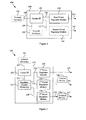
Figure 2 shows a block diagram of asystem 200 comprising an exemplary power management integratedcircuit 210 utilizing received power supply information, in accordance with various aspects of the present invention. Theexemplary system 200 may, for example and without limitation, share various characteristics with theexemplary system 100 illustrated inFigure 1 and discussed previously. - The exemplary power management integrated
circuit 210 may comprise acommunication interface module 220. The exemplarycommunication interface module 220 may, for example and without limitation, share various characteristics with the exemplarycommunication interface module 120 illustrated inFigure 1 and discussed previously. For example, thecommunication interface module 220 may receivepower supply information 207 from at least oneelectrical device 205 external to theintegrated circuit 210. As discussed previously with regard to theexemplary system 100 illustrated inFigure 1 , thecommunication interface module 220 may also, for example, receive power supply information from at least one electrical device internal to theintegrated circuit 210. Though such an internal electrical device is not illustrated inFigure 2 and the following discussion will generally discuss an exemplary scenario including an electrical device external to theintegrated circuit 210, the scope of various aspects of the present invention should by no means be limited by such externality - Such power supply information may, for example, comprise information related to a first electrical power. Such power supply information may, for example, also comprise information related to a second electrical power and/or nth electrical power. The electrical device(s) 205 may also, for example and without limitation, share various characteristics with the exemplary electrical device(s) 105 illustrated in
Figure 1 and discussed previously. - The exemplary
integrated circuit 210 may also comprise one or moreregulator control modules 225 that process at least aportion 221 of thepower supply information 207 received by thecommunication interface module 220 and generates regulator control signals 226-228. The regulator control module(s) 225 may, for example, generate the regulator control signals 226-228 based, at least in part, on at least aportion 221 of thepower supply information 207. - In the
exemplary system 100 illustrated inFigure 1 and discussed previously, the individualpower regulator modules exemplary system 200 illustrated inFigure 2 , at least a portion of such processing is performed by the regulator control module(s) 225. For example, the one or more regulator control module(s) 225 may be at least partially integrated (e.g., in hardware and/or software), which may foster a more centralized approach for determining the plurality of regulator control signals 226-228 than the more distributed approach exemplified by thesystem 100 illustrated inFigure 1 . - The regulator control signals 226-228 may control various operational aspects of respective
power regulator modules power regulator modules power regulator modules - Also for example, the regulator control signals 226-228 may comprise information controlling various specific operational aspects of respective
power regulator modules power regulator modules power regulator modules - As indicated previously, the exemplary
integrated circuit 210 may comprise first, second and thirdpower regulator modules power regulator modules power regulator modules Figure 1 and discussed previously. - For example, the
first regulator module 230 may receive the first regulator control signal 226 from the regulator control module(s) 225. The firstpower regulator module 230 may then, for example, determine a firstregulated power signal 235 based at least in part on the firstregulator control signal 226, where the firstregulated power signal 235 corresponds to first electrical power (e.g., the first electrical power to which at least a portion of the received power supply information is related). - As mentioned previously, the first
regulated power signal 235 may correspond to the first electrical power in any of a variety of manners. In theexemplary system 200 illustrated inFigure 2 , the firstregulated power signal 235 comprises the first electrical power. The firstpower regulator module 230 might, for example, generate the first regulated power signal 235 (comprising the first electrical power) utilizing only circuitry internal to theintegrated circuit 210. - The second
power regulator module 240 may, for example, receive the second regulator control signal 227 from the regulator control module(s) 225. The secondpower regulator module 240 may then, for example, determine a secondregulated power signal 245 based at least in part on the secondregulator control signal 227, where the secondregulated power signal 245 corresponds to second electrical power (e.g., second electrical power to which at least a portion of the received power supply information is related). - As mentioned previously, the second
regulated power signal 245 may correspond to the second electrical power in any of a variety of manners. In theexemplary system 200 illustrated inFigure 2 , the secondregulated power signal 245 comprises the second electrical power. The secondpower regulator module 240 may, for example, generate the second regulated power signal 245 (comprising the second electrical power) in conjunction withpower supply circuitry 246 external to theintegrated circuit 210. In a non-limiting exemplary scenario, such externalpower supply circuitry 246 may comprise various switching power supply circuitry (e.g., electrical components in a boost converter configuration). - The third
power regulator module 250 may, for example, receive the third regulator control signal 228 from the regulator control module(s) 225. The thirdpower regulator module 250 may then, for example, determine a thirdregulated power signal 255 based at least in part on the thirdregulator control signal 228, where the thirdregulated power signal 255 corresponds to third electrical power (e.g., third electrical power to which at least a portion of the received power supply information is related). - As mentioned previously, the third
regulated power signal 255 may correspond to the third electrical power in any of a variety of manners. In theexemplary system 200 illustrated inFigure 2 , the thirdregulated power signal 255 comprises one or more signals or subsignals that causepower supply circuitry 256 external to theintegrated circuit 210 to output the thirdelectrical power 257. In a non-limiting exemplary scenario, such externalpower supply circuitry 256 may comprise various switching power supply circuitry (e.g., electrical components in a buck converter configuration). - The
exemplary system 200 illustrated inFigure 2 and discussed previously was presented to provide specific illustrations of generally broader aspects of the present invention. Accordingly, the scope of various aspects of the present invention should not be limited by characteristics of theexemplary system 200. -
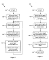
Figure 3 illustrates a flow diagram of amethod 300 for providing regulated signal(s) corresponding to electrical power(s) from a power management integrated circuit utilizing received power supply information, in accordance with various aspects of the present invention. Theexemplary method 300 may, for example and without limitation, share various characteristics with the functionality discussed previously with regard to theexemplary systems Figures 1-2 and discussed previously. - The
exemplary method 300 may begin atstep 310. The method 300 (and other methods discussed herein) may begin for any of a variety of reasons. For example and without limitation, themethod 300 may begin automatically in response to a power-up or reset condition. Also for example, themethod 300 may begin in response to a command, either from a user or from a system component. Further for example, themethod 300 may execute periodically or in response to a detected system or environmental condition. Accordingly, the scope of various aspects of the present invention should not be limited by characteristics of any particular initiating cause or condition. - The
exemplary method 300 may, atstep 320, comprise determining initial characteristics of first electrical power. Step 320 may comprise determining such characteristics in any of variety of manners. For example and without limitation, step 320 may comprise determining such initial characteristics by utilizing default characteristics or utilizing stored information of previous characteristics. - Step 320 may also, for example, comprise determining initial characteristics of a first regulated power signal that corresponds to first electrical power. Such correspondence was generally discussed previously in the discussion of
Figure 1 . For example and without limitation, step 320 may comprise determining such initial characteristics by utilizing default characteristics or utilizing stored information of previous characteristics. - In general,
step 320 may comprise determining initial characteristics of first electrical power and/or initial characteristics of a corresponding first regulated power signal. Accordingly, the scope of various aspects of the present invention should not be limited by a particular manner of determining initial characteristics of electrical power or corresponding signals. - The
exemplary method 300 may, atstep 330, comprise outputting the first regulated power signal (e.g., as determined atstep 320 or step 350, to be discussed later) to at least one electrical device external (or internal) to the integrated circuit. Step 330 may, for example and without limitation, share various functional characteristics with the exemplarypower regulator modules Figures 1-2 . Though the following discussion generally refers to an electrical device external to the integrated circuit, the scope of various aspects of the present invention should by no means be limited by such externality. For example and without limitation, the electrical device may, in accordance with various aspects of the present invention, be internal to the integrated circuit. - For example, step 330 may comprise outputting the first regulated power signal to power supply circuitry external to the integrated circuit. Such power supply circuitry may, for example, provide the first electrical power to at least one electrical device (e.g., an electrical device that might provide power supply information, as received at
step 340, to be discussed later). Also for example, step 330 may comprise outputting the first regulated power signal directly to at least one electrical device (e.g., an electrical device that might provide power supply information, as received atstep 340, to be discussed later). - In general,
step 330 may comprise outputting the first regulated power signal to at least one electrical device external to the power management integrated circuit. Accordingly, the scope of various aspects of the present invention should not be limited by characteristics of a particular regulated power signal or particular electrical device(s) external to the integrated circuit. - The
exemplary method 300 may, atstep 340, comprise receiving power supply information from one or more electrical devices external to the power management integrated circuit. The power supply information may, for example, comprise information related to a first electrical power. Step 340 may, for example and without limitation, share various functional characteristics with the exemplarycommunication interface modules Figures 1-2 and discussed previously. - For example, the power supply information may comprise information related to various characteristics of electrical power. Such characteristics may, for example and without limitation, comprise voltage and/or current level, voltage and/or current variability, noise, ripple, load response characteristics, energy efficiency level, etc. The power supply information may, for example, comprise analog and/or digital information.
- Step 340 may, for example, comprise receiving the power supply information in any of a variety of manners. For example, step 340 may comprise receiving the power supply information over an analog or digital communication link. The communication link may, for example, be serial or parallel. The communication link may, for example, comprise a dedicated information bus or a shared information bus. Step 340 may, for example, comprise receiving the power supply information utilizing any of a large variety of communication media and/or communication protocols.
- Step 340 may comprise receiving the power supply information from any of a variety of devices external to the power management integrated circuit. For example, step 340 may comprise receiving the power supply information from at least one electrical device that receives and utilizes the first electrical power (e.g., corresponding to the regulated power signal output at step 330). Also for example, step 340 may comprise receiving the power supply information from an electrical device monitoring operation of another device that receives and utilizes the first electrical power. Further for example, step 340 may comprise receiving the power supply information from an electrical device that is communicatively coupled to an electrical device that receives and utilizes the first electrical power. Still further for example, step 340 may comprise receiving the power supply information from an electrical device associated with the production of the first electrical power. Accordingly, the scope of various aspects of the present invention should not be limited by characteristics of a particular device that step 340 might receive power supply information from.
- The
exemplary method 300 may, atstep 350, comprise determining a first regulated power signal based, at least in part, on a portion of the power supply information (e.g., as received at step 340). The first regulated power signal may, for example, correspond to the first electrical power. Step 350 may, for example and without limitation, share various functional characteristics with thepower regulator modules regulator control module 225 illustrated inFigures 1-2 and discussed previously. - For example, the first regulated power signal may comprise the first electrical power. In such a scenario, step 350 might comprise generating the first electrical power using only electrical components internal to the integrated circuit or utilizing electrical components (e.g., power supply circuitry) external to the integrated circuit. Also for example, the first regulated power signal may comprise a signal that interacts with power supply circuitry external to the integrated circuit, which in turn generates the first electrical power.
- Step 350 might comprise utilizing any of a variety of power regulator circuitry. For example, step 350 might comprise utilizing circuitry comprising characteristics of at least a front-end portion (if not a whole portion) of a linear voltage regulator, a switching regulator (e.g., a buck converter, boost converter, buck-boost converter, charge pump, etc.), or other types of known or yet to be developed regulator circuits. Accordingly, the scope of various aspects of the present invention should not be limited by characteristics of particular type of circuitry that step 350 might utilize.
- In an exemplary scenario where the first regulated power signal (e.g., as output by step 330) interacts with circuitry external to the integrated circuit to provide the first electrical power, such external circuitry may comprise electrical components in any of a variety of configurations. For example and without limitation, such electrical component configurations may comprise at least portions of a buck converter, boost converter, buck-boost converter, charge pump, or other types of known or yet to be developed power regulator circuits. Accordingly, the scope of various aspects of the present invention should not be limited by characteristics of particular power supply or power regulator circuitry architectures.
- As mentioned previously,
step 350 may comprise determining a first regulated power signal based at least in part on a portion of the power supply information, where the first regulated power signal corresponds to the first electrical power. Step 350 may comprise making such a determination in any of a variety of manners, depending on the particular operating scenario. - For example and without limitation, step 350 may comprise determining one or more characteristics of the first electrical power based, at least in part, on a portion of the power supply information. Step 350 may then, for example, comprise determining the first regulated power signal based on the determined characteristic(s).
- In a non-limiting exemplary scenario, the power supply information (e.g., as received at step 340) may comprise information of a desired voltage level for the first electrical power. Step 350 may, for example, comprise determining the first regulated power signal based on such information. For example, step 350 may comprise directly outputting a first regulated power signal that comprises the first electrical power characterized by the desired voltage level (or other voltage level based on the desired voltage level). Also for example, step 350 may comprise outputting a first regulated power signal that, when interacting with circuitry external to the integrated circuit, causes the external circuitry to output the first electrical power characterized by the desired voltage level (or other voltage level based on the desired voltage level).
- In another non-limiting exemplary scenario, the power supply information may comprise information of maximum desired voltage variability. Step 350 may, for example, comprise determining the first regulated power signal based on such information. For example, step 350 may comprise directly outputting a first regulated power signal that comprises the first electrical power characterized by the maximum desired voltage variability (or voltage variability based on the maximum desired voltage variability). Also for example, step 350 may comprise outputting a first regulated power signal that, when interacting with circuitry external to the integrated circuit, causes the external circuitry to output the first electrical power characterized by the maximum desired voltage variability (or voltage variability based on the maximum desired voltage variability).
- In yet another non-limiting exemplary scenario, the power supply information may comprise information of a minimum energy-efficiency level. Step 350 may comprise determining the first regulated power signal based on such information. For example, step 350 may comprise directly outputting a first regulated power signal that comprises the first electrical power characterized by the minimum energy-efficiency level (or energy-efficiency level based on the minimum energy-efficiency level). Also for example, step 350 may comprise outputting a first regulated power signal that, when interacting with circuitry external to the integrated circuit, causes the external circuitry to output the first electrical power characterized by the minimum energy-efficiency level (or energy-efficiency level based on the minimum energy-efficiency level).
- In general,
step 350 may comprise determining a first regulated power signal based at least in part on a portion of the power supply information, wherein the first regulated power signal corresponds to the first electrical power. Accordingly, the scope of various aspects of the present invention should not be limited by characteristics of any particular type of power supply information or a particular manner of determining a regulated power signal based on such information. - After
step 350, the execution flow of theexemplary method 300 may flow back up to step 330, which may output the first regulated power signal as determined bystep 350. Such flow is merely exemplary and should by no means limit the scope of various aspects of the present invention. - The previous discussion of the
exemplary method 300 discussed determining and outputting a single first regulated power signal. A single regulated power signal was discussed for illustrative purposes only and should not limit the scope of various aspects of the present invention. For example, themethod 300 is readily extensible to determining and outputting a plurality of regulated power signals, which may, for example, correspond to a plurality of respective electrical powers or may correspond to a common electrical power. - For example, the power supply information received at
step 340 may comprise information related to a second electrical power. Step 350 may then, for example, comprise determining a second regulated power signal based at least in part on a portion of the power supply information, where the second regulated power signal corresponds to the second electrical power. Theexemplary method 300 may similarly, for example, extend to receiving power supply information related to n electrical powers, and determining and outputting one or more regulated power signals corresponding to the n electrical powers. Accordingly, the scope of various aspects of the present invention should not be limited by the determination and generation of a single regulated power signal. - The
exemplary method 300 illustrated inFigure 3 and discussed previously was presented to provide specific illustrations of generally broader aspects of the present invention. Accordingly, the scope of various aspects of the present invention should not be limited by characteristics of theexemplary method 300. -
Figure 4 illustrates a flow diagram of amethod 400 for providing regulated signal(s) corresponding to electrical power(s) from a power management integrated circuit utilizing power supply information received from a plurality of sources, in accordance with various aspects of the present invention. Themethod 400 may, for example and without limitation, share various functional characteristics with theexemplary systems Figures 1-2 and discussed previously. Themethod 400 may also, for example and without limitation, share various characteristics with theexemplary method 300 illustrated inFigure 3 and discussed previously. - As mentioned previously, various aspects of the present invention may receive and process power supply information from a plurality of sources. The
exemplary method 400 provides a non-limiting exemplary illustration of such receipt and processing. Themethod 400, or various portions thereof, may for example, be executed in conjunction with theexemplary method 300 illustrated inFigure 3 . Alternatively for example, themethod 400 may be executed independently. Accordingly, the scope of various aspects of the present invention should not be limited by characteristics of method independence or interrelationship with other methods. - The
exemplary method 400 may, atstep 420, comprise receiving power supply information from a first electrical device external (or internal) to the integrated circuit, where the power supply information comprises information related to a first electrical power. Similarly, theexemplary method 400 may, atstep 430, comprise receiving power supply information from a second electrical device external to the integrated circuit, where the power supply information comprises information related to the first electrical power.Steps step 340 of theexemplary method 300 illustrated inFigure 3 and discussed previously. Also, steps 420 and 430 may share various functional characteristics with thecommunication interface modules Figures 1-2 and discussed previously. Note that though the present discussion will focus on receiving and processing power supply information from first and second external devices, the discussion is readily extensible to an n-device scenario and/or a scenario including one or more electrical devices internal to the integrated circuit. - The
exemplary method 400 may, atstep 440, comprise determining a first regulated power signal based at least in part on a portion of the power supply information, where the first regulated power signal corresponds to the first electrical power. Step 440 may, for example and without limitation, share various characteristics withstep 350 of theexemplary method 300 illustrated inFigure 3 and discussed previously. - For example, step 440 may comprise first processing the power supply information to determine one or more characteristics of the first electrical power. Step 440 may then, for example, output the first regulated power signal comprising the first electrical power having the determined characteristic(s). Alternatively for example, step 440 may determine characteristics of the first regulated power signal, which when output, will cause other circuitry to output the first electrical power having the determined characteristic(s).
- As mentioned previously with regard to a portion of the functionality of the
exemplary systems step 440 may comprise arbitrating between power supply needs of the first and second (or n) devices from which the power supply information was received. Such arbitration may, for example and without limitation, comprise determining characteristics of the first electrical power (and thus, the corresponding first regulated power signal) based, at least in part, on priority of the electrical devices. For example, step 440 may comprise determining characteristics of the first electrical power based solely on the electrical device with the highest priority. Alternatively for example, step 440 may comprise determining characteristics of the first electrical power based on a priority-based weighted average of power supply needs of the electrical devices. Further for example, step 440 may comprise determining characteristics of the first electrical power by averaging respective power supply needs of the electrical devices. - In general,
exemplary step 440 may, in determining characteristics of the first electrical power and/or characteristics of the corresponding first regulated power signal, may arbitrate between needs of a plurality of electrical devices. Accordingly, the scope of various aspects of the present invention should not be limited by characteristics of any particular manner of performing such arbitration. - The
exemplary method 400 may, atstep 450, comprise outputting the first regulated power signal to at least one electrical device external to the integrated circuit. Step 450 may, for example and without limitation, share various characteristics withstep 330 of theexemplary method 300 illustrated inFigure 3 and discussed previously. - After performing
step 450, execution flow of theexemplary method 400 may flow to step 460 for performing continued processing. Such continued processing may comprise any of variety of continued processing characteristics, including stopping, looping back to aprevious method 400 step, entering a wait state, etc. Accordingly, the scope of various aspects of the present invention should not be limited by characteristics of any particular type of continued processing. - The previous discussion of the
exemplary method 400 discussed determining and outputting a single first regulated power signal. A single regulated power signal was discussed for illustrative purposes only and should not limit the scope of various aspects of the present invention. For example, themethod 400 is readily extensible to determining and outputting a plurality of regulated power signals, which may, for example, correspond to a plurality of respective electrical powers or may correspond to a common electrical power. - For example, the power supply information received at
steps exemplary method 400 may similarly, for example, extend to receiving power supply information related to n electrical powers, and determining and outputting one or more regulated power signals corresponding to the n electrical powers. Accordingly, the scope of various aspects of the present invention should not be limited by the determination and generation of a single regulated power signal. - The
exemplary method 400 illustrated inFigure 4 and discussed previously was presented to provide specific illustrations of generally broader aspects of the present invention. Accordingly, the scope of various aspects of the present invention should not be limited by characteristics of theexemplary system 400. - It should be stressed that various aspects of the present invention may be performed by hardware, a processor executing software instructions, or a combination thereof. Accordingly, the scope of various aspects of the present invention should not be limited by characteristics of any particular implementation.
- In summary, various aspects of the present invention provide a system and method for providing power control in a power management integrated circuit. While the invention has been described with reference to certain aspects and embodiments, it will be understood by those skilled in the art that various changes may be made and equivalents may be substituted without departing from the scope of the invention. In addition, many modifications may be made to adapt a particular situation or material to the teachings of the invention without departing from its scope. Therefore, it is intended that the invention not be limited to the particular embodiment disclosed, but that the invention will include all embodiments falling within the scope of the appended claims.
Advantageously, the communication interface module is adapted to receive power supply information from at least one electrical device external to the power management circuit.
According to an aspect of the invention, a power management integrated circuit is provided comprising:
Advantageously, the power supply information comprises information related to voltage of the first electrical power.
Advantageously, the communication interface module comprises a digital signal interface, and the power supply information comprises digital information related to the first electrical power.
According to an aspect of the invention, in a power management integrated circuit, a method for controlling electrical power is provided, the method comprising:
Advantageously, the power supply information comprises information related to voltage level of the first electrical power.
Advantageously, receiving power supply information comprises receiving digital power supply information related to the first electrical power.
Advantageously, the regulated power signal comprises the first electrical power.
Advantageously, the regulated power signal causes power supply circuitry external to the integrated circuit to output the first electrical power.
Advantageously, outputting the regulated power signal comprises outputting the regulated power signal to power supply circuitry external to the integrated circuit.
Advantageously, outputting the regulated power signal comprises outputting the regulated power signal to the at least one electrical device from which the power supply information was received.
Advantageously, receiving power supply information comprises receiving power supply information from at least one electrical device that receives and utilizes the first electrical power.
Advantageously, the power supply information comprises information related to a second electrical power, and further comprising:
Claims (10)
- A power management integrated circuit (110) comprising:a communication interface module (120) adapted to receive power supply information (107) from a plurality of electrical devices (105) external to the integrated circuit (110), wherein the power supply information (107) comprises information related to a first electrical power; anda power regulator module (130) adapted to:determine a regulated power signal (135) based at least in part on a portion of the power supply information (107), wherein the regulated power signal (135) corresponds to the first electrical power; characterized in that means are provided toprocess the power supply information (107) to arbitrate between power supply needs of the plurality of electrical devices (105); andoutput the regulated power signal (135) to at least one electrical device (105).
- The power management integrated circuit (110) of claim 1, wherein the power regulator module (130) is adapted to determine a regulated power signal (135) by determining one or more characteristic(s) of the first electrical power based at least in part on a portion of the power supply information (107), wherein the regulated power signal (135) corresponds to the first electrical power characterized by the determined characteristic(s).
- The power management integrated circuit (110) of claim 1, wherein the power supply information (107) comprises information related to voltage level of the first electrical power.
- The power management integrated circuit (110) of claim 1, wherein the communication interface module (120) comprises a digital signal interface, and the power supply information (107) comprises digital information related to the first electrical power.
- The power management integrated circuit (110) of claim 1, further comprising
a regulator control module (225) adapted to process the received power supply information (107) and generate a first regulator control signal (226) based, at least in part, on the received power supply information (107). - The power management integrated circuit (110) of claim 5, wherein the regulator control module (225) is adapted to generate the first regulator control signal (226) by:determining one or more characteristics of the first electrical power based at least in part on a portion of the power supply information (107);anddetermining the first regulator control signal (226) based, at least in part, on the determined characteristic(s) of the first electrical power;wherein the regulated power signal (135) output by the power regulator module (130) corresponds to the first electrical power characterized by the determined characteristic(s).
- The power management integrated circuit (110) of claim 5, wherein:the power supply information (107) comprises information related to a second electrical power; andthe regulator control module (225) is adapted to process the received power supply information (107) and generate a second regulator control signal (227) based at least in part on the received power supply information (107); andfurther comprising a second power regulator module (140) adapted to:determine a second regulated power signal (145) based at least in part on the second regulator control signal (227), wherein the second regulated power signal (145) corresponds to the second electrical power; andoutput the second regulated power signal (145) to at least one electrical device (105) external to the power management integrated circuit (110).
- In a power management integrated circuit (110), a method (300) for controlling electrical power, the method (300) comprising:receiving power supply information (107) from a plurality of electrical devices (105) external to the integrated circuit (110), wherein the power supply information (107) comprises information related to a first electrical power;determining a regulated power signal (135) based at least in part on a portion of the power supply information (107), wherein the regulated power signal (135) corresponds to the first electrical power; characterized in that the method further comprisesprocessing the power supply information (107) to arbitrate between power supply needs of the plurality of electrical devices (105); andoutputting the regulated power signal (135) to at least one electrical device (105) external to the integrated circuit (110).
- The method (300) of claim 8, wherein determining a regulated power signal (135) comprises determining one or more characteristics of the first electrical power based at least in part on a portion of the power supply information (107), and wherein the regulated power signal (135) corresponds to the first electrical power characterized by the determined characteristic(s).
- The method (300) of claim 8, wherein the power supply information (107) comprises information related to voltage level of the first electrical power.
Applications Claiming Priority (2)
| Application Number | Priority Date | Filing Date | Title |
|---|---|---|---|
| US58408804P | 2004-06-29 | 2004-06-29 | |
| US11/158,141 US7581122B2 (en) | 2004-06-29 | 2005-06-21 | Power supply integrated circuit with feedback control |
Publications (2)
| Publication Number | Publication Date |
|---|---|
| EP1612909A1 EP1612909A1 (en) | 2006-01-04 |
| EP1612909B1 true EP1612909B1 (en) | 2011-11-30 |
Family
ID=34981308
Family Applications (1)
| Application Number | Title | Priority Date | Filing Date |
|---|---|---|---|
| EP05013692A Active EP1612909B1 (en) | 2004-06-29 | 2005-06-24 | Power supply integrated circuit with feedback control |
Country Status (3)
| Country | Link |
|---|---|
| US (3) | US7581122B2 (en) |
| EP (1) | EP1612909B1 (en) |
| TW (1) | TWI302238B (en) |
Families Citing this family (25)
| Publication number | Priority date | Publication date | Assignee | Title |
|---|---|---|---|---|
| US7295949B2 (en) * | 2004-06-28 | 2007-11-13 | Broadcom Corporation | Energy efficient achievement of integrated circuit performance goals |
| US7707434B2 (en) * | 2004-06-29 | 2010-04-27 | Broadcom Corporation | Power control bus for carrying power control information indicating a power supply voltage variability |
| US7509507B2 (en) * | 2004-06-29 | 2009-03-24 | Broadcom Corporation | Multi-regulator power supply chip with common control bus |
| US7925906B2 (en) * | 2004-06-29 | 2011-04-12 | Broadcom Corporation | Multi-voltage multi-battery power management unit |
| US7581122B2 (en) * | 2004-06-29 | 2009-08-25 | Broadcom Corporation | Power supply integrated circuit with feedback control |
| US7783924B2 (en) * | 2005-08-26 | 2010-08-24 | General Electric Company | System and method for communication between a controller and a power supply using a communication interface |
| JP2007201455A (en) * | 2005-12-28 | 2007-08-09 | Matsushita Electric Ind Co Ltd | Semiconductor integrated circuit device |
| US7782222B2 (en) * | 2006-02-28 | 2010-08-24 | Realtek Semiconductor Corp. | Voltage regulating power supply for noise sensitive circuits |
| US8650925B2 (en) | 2007-01-05 | 2014-02-18 | Apple Inc. | Extrusion method for fabricating a compact tube with internal features |
| US9118990B2 (en) * | 2007-01-06 | 2015-08-25 | Apple Inc. | Connectors designed for ease of use |
| US8712071B2 (en) * | 2007-01-05 | 2014-04-29 | Apple Inc. | Headset electronics |
| EP3196551B1 (en) | 2007-01-06 | 2019-05-29 | Apple Inc. | Earbud comprising a plurality of electrical contacts and earbud system comprising an earbud and a charger |
| ATE554517T1 (en) | 2007-01-06 | 2012-05-15 | Apple Inc | HEADSET CONNECTOR FOR SELECTIVE CONNECTION OF SIGNALS DEPENDING ON THE PARTICULAR ORIENTATION OF THE CONNECTED CONNECTOR |
| TWI381261B (en) * | 2008-07-18 | 2013-01-01 | Asia Optical Co Inc | Power management devices and power management methods |
| US8559865B2 (en) | 2008-07-31 | 2013-10-15 | Qualcomm Incorporated | Method and apparatus for providing jammer detection in a receiver |
| CN102255395B (en) * | 2011-06-27 | 2014-11-05 | 华为终端有限公司 | Electronic equipment and method for supplying power to at least two different loads by single power supply |
| US9789558B2 (en) | 2011-08-18 | 2017-10-17 | Illinois Tool Works Inc. | System and device operating using a welding power bus |
| US9141166B2 (en) * | 2011-12-13 | 2015-09-22 | Intel Corporation | Method, apparatus, and system for energy efficiency and energy conservation including dynamic control of energy consumption in power domains |
| US9292025B2 (en) | 2011-12-19 | 2016-03-22 | Mediatek Singapore Pte. Ltd. | Performance, thermal and power management system associated with an integrated circuit and related method |
| JP5672251B2 (en) | 2012-01-27 | 2015-02-18 | 株式会社デンソー | Vehicle power supply control device |
| JP6145669B2 (en) * | 2012-03-27 | 2017-06-14 | パナソニックIpマネジメント株式会社 | Power management apparatus and power management system |
| KR20140029565A (en) * | 2012-08-28 | 2014-03-11 | 삼성전자주식회사 | Apparatus and method of power control |
| US9119162B2 (en) * | 2013-02-19 | 2015-08-25 | Qualcomm Incorporated | Parallel arrangement of asynchronous buck converters for advanced power capability |
| TWI533553B (en) | 2014-10-21 | 2016-05-11 | 國立清華大學 | Power management method and controller thereof |
| US10582284B2 (en) | 2015-09-30 | 2020-03-03 | Apple Inc. | In-ear headphone |
Family Cites Families (18)
| Publication number | Priority date | Publication date | Assignee | Title |
|---|---|---|---|---|
| US5483656A (en) * | 1993-01-14 | 1996-01-09 | Apple Computer, Inc. | System for managing power consumption of devices coupled to a common bus |
| US6356984B1 (en) * | 1998-06-30 | 2002-03-12 | Sun Microsystems, Inc. | Digital data processing system having a data bus and a control bus |
| US6668328B1 (en) * | 1999-05-19 | 2003-12-23 | Globespanvirata, Inc. | Computer system having a power supply for coupling signals to a power line network and transmitting infrared signal to at least one peripheral card |
| US6396169B1 (en) * | 2000-02-29 | 2002-05-28 | 3Com Corporation | Intelligent power supply control for electronic systems requiring multiple voltages |
| US6594771B1 (en) * | 2000-04-13 | 2003-07-15 | Hewlett-Packard Development Company, L.P. | Method and apparatus for managing power in an electronic device |
| US6823465B2 (en) * | 2001-04-30 | 2004-11-23 | Intel Corporation | Establishment of voltage of a terminal at a voltage level in response to validating the indication of the voltage to be supplied to the terminal |
| FI116702B (en) | 2001-12-20 | 2006-01-31 | Nokia Corp | Dynamic power control in integrated circuits |
| KR100505638B1 (en) * | 2002-08-28 | 2005-08-03 | 삼성전자주식회사 | Apparatus and method for saving and restoring of working context |
| US6949916B2 (en) * | 2002-11-12 | 2005-09-27 | Power-One Limited | System and method for controlling a point-of-load regulator |
| US7000125B2 (en) * | 2002-12-21 | 2006-02-14 | Power-One, Inc. | Method and system for controlling and monitoring an array of point-of-load regulators |
| US7209719B2 (en) * | 2003-01-28 | 2007-04-24 | Gateway Inc. | Home power line network connected phone |
| US7105950B2 (en) * | 2003-09-26 | 2006-09-12 | Hewlett-Packard Development Company, L.P. | Power management in a system having a plurality of power supplies |
| US7085943B2 (en) * | 2003-09-26 | 2006-08-01 | Freescale Semiconductor, Inc. | Method and circuitry for controlling supply voltage in a data processing system |
| US7203849B2 (en) * | 2003-12-12 | 2007-04-10 | Hewlett-Packard Development Company, L.P. | Method and system for distributing power to networked devices |
| US7190210B2 (en) * | 2004-03-25 | 2007-03-13 | Integral Wave Technologies, Inc. | Switched-capacitor power supply system and method |
| US7581122B2 (en) * | 2004-06-29 | 2009-08-25 | Broadcom Corporation | Power supply integrated circuit with feedback control |
| US7509507B2 (en) * | 2004-06-29 | 2009-03-24 | Broadcom Corporation | Multi-regulator power supply chip with common control bus |
| US7308590B2 (en) * | 2004-10-15 | 2007-12-11 | Intel Corporation | Automatic dynamic processor operating voltage control |
-
2005
- 2005-06-21 US US11/158,141 patent/US7581122B2/en active Active
- 2005-06-24 EP EP05013692A patent/EP1612909B1/en active Active
- 2005-06-28 TW TW094121606A patent/TWI302238B/en active
-
2009
- 2009-08-18 US US12/542,865 patent/US8868935B2/en active Active
-
2014
- 2014-10-14 US US14/513,879 patent/US9285815B2/en active Active
Also Published As
| Publication number | Publication date |
|---|---|
| US7581122B2 (en) | 2009-08-25 |
| US20050285575A1 (en) | 2005-12-29 |
| US20090302826A1 (en) | 2009-12-10 |
| TWI302238B (en) | 2008-10-21 |
| US20150032280A1 (en) | 2015-01-29 |
| US8868935B2 (en) | 2014-10-21 |
| TW200627120A (en) | 2006-08-01 |
| EP1612909A1 (en) | 2006-01-04 |
| US9285815B2 (en) | 2016-03-15 |
Similar Documents
| Publication | Publication Date | Title |
|---|---|---|
| EP1612909B1 (en) | Power supply integrated circuit with feedback control | |
| EP1612911B1 (en) | On-board performance monitor and power control system | |
| EP1612910B1 (en) | On-board power supply monitor and power control system | |
| EP1612908B1 (en) | Multi-regulator power supply chip with common control bus | |
| US7925906B2 (en) | Multi-voltage multi-battery power management unit | |
| JP5816747B2 (en) | Power management for electronic devices | |
| JP2004531787A (en) | System for controlling or regulating | |
| US9136764B2 (en) | Apparatuses and system and method for auto-configuration of a power control system | |
| US9112410B2 (en) | Apparatuses and system having separate power control and timing control of a power control system and related method | |
| US11177737B2 (en) | Switching control for power converters | |
| EP2775601B1 (en) | Adaptation of operating mode ranges of switching regulators by means of programmable voltage thresholds | |
| CN102171626B (en) | For the method and apparatus saving energy in the microprocessor | |
| CN100451884C (en) | Power supply integrated circuit with feedback control | |
| CN116316423A (en) | Auxiliary control circuit and switching power supply | |
| CN116647117A (en) | Power supply control system and electronic equipment |
Legal Events
| Date | Code | Title | Description |
|---|---|---|---|
| PUAI | Public reference made under article 153(3) epc to a published international application that has entered the european phase |
Free format text: ORIGINAL CODE: 0009012 |
|
| AK | Designated contracting states |
Kind code of ref document: A1 Designated state(s): AT BE BG CH CY CZ DE DK EE ES FI FR GB GR HU IE IS IT LI LT LU MC NL PL PT RO SE SI SK TR |
|
| AX | Request for extension of the european patent |
Extension state: AL BA HR LV MK YU |
|
| 17P | Request for examination filed |
Effective date: 20060704 |
|
| AKX | Designation fees paid |
Designated state(s): DE FR GB |
|
| 17Q | First examination report despatched |
Effective date: 20070412 |
|
| RAP1 | Party data changed (applicant data changed or rights of an application transferred) |
Owner name: BROADCOM CORPORATION |
|
| GRAP | Despatch of communication of intention to grant a patent |
Free format text: ORIGINAL CODE: EPIDOSNIGR1 |
|
| GRAS | Grant fee paid |
Free format text: ORIGINAL CODE: EPIDOSNIGR3 |
|
| GRAA | (expected) grant |
Free format text: ORIGINAL CODE: 0009210 |
|
| AK | Designated contracting states |
Kind code of ref document: B1 Designated state(s): DE FR GB |
|
| REG | Reference to a national code |
Ref country code: GB Ref legal event code: FG4D |
|
| REG | Reference to a national code |
Ref country code: DE Ref legal event code: R081 Ref document number: 602005031426 Country of ref document: DE Owner name: AVAGO TECHNOLOGIES GENERAL IP (SINGAPORE) PTE., SG Free format text: FORMER OWNER: BROADCOM CORP., IRVINE, CALIF., US |
|
| REG | Reference to a national code |
Ref country code: DE Ref legal event code: R096 Ref document number: 602005031426 Country of ref document: DE Effective date: 20120202 |
|
| PLBE | No opposition filed within time limit |
Free format text: ORIGINAL CODE: 0009261 |
|
| STAA | Information on the status of an ep patent application or granted ep patent |
Free format text: STATUS: NO OPPOSITION FILED WITHIN TIME LIMIT |
|
| 26N | No opposition filed |
Effective date: 20120831 |
|
| REG | Reference to a national code |
Ref country code: DE Ref legal event code: R097 Ref document number: 602005031426 Country of ref document: DE Effective date: 20120831 |
|
| REG | Reference to a national code |
Ref country code: FR Ref legal event code: ST Effective date: 20130228 |
|
| PG25 | Lapsed in a contracting state [announced via postgrant information from national office to epo] |
Ref country code: FR Free format text: LAPSE BECAUSE OF NON-PAYMENT OF DUE FEES Effective date: 20120702 |
|
| PGFP | Annual fee paid to national office [announced via postgrant information from national office to epo] |
Ref country code: GB Payment date: 20160627 Year of fee payment: 12 |
|
| REG | Reference to a national code |
Ref country code: DE Ref legal event code: R082 Ref document number: 602005031426 Country of ref document: DE Representative=s name: BOSCH JEHLE PATENTANWALTSGESELLSCHAFT MBH, DE Ref country code: DE Ref legal event code: R081 Ref document number: 602005031426 Country of ref document: DE Owner name: AVAGO TECHNOLOGIES INTERNATIONAL SALES PTE. LT, SG Free format text: FORMER OWNER: BROADCOM CORPORATION, IRVINE, CALIF., US Ref country code: DE Ref legal event code: R081 Ref document number: 602005031426 Country of ref document: DE Owner name: AVAGO TECHNOLOGIES GENERAL IP (SINGAPORE) PTE., SG Free format text: FORMER OWNER: BROADCOM CORPORATION, IRVINE, CALIF., US |
|
| REG | Reference to a national code |
Ref country code: GB Ref legal event code: 732E Free format text: REGISTERED BETWEEN 20171005 AND 20171011 |
|
| GBPC | Gb: european patent ceased through non-payment of renewal fee |
Effective date: 20170624 |
|
| PG25 | Lapsed in a contracting state [announced via postgrant information from national office to epo] |
Ref country code: GB Free format text: LAPSE BECAUSE OF NON-PAYMENT OF DUE FEES Effective date: 20170624 |
|
| REG | Reference to a national code |
Ref country code: DE Ref legal event code: R082 Ref document number: 602005031426 Country of ref document: DE Representative=s name: BOSCH JEHLE PATENTANWALTSGESELLSCHAFT MBH, DE Ref country code: DE Ref legal event code: R081 Ref document number: 602005031426 Country of ref document: DE Owner name: AVAGO TECHNOLOGIES INTERNATIONAL SALES PTE. LT, SG Free format text: FORMER OWNER: AVAGO TECHNOLOGIES GENERAL IP (SINGAPORE) PTE. LTD., SINGAPORE, SG |
|
| PGFP | Annual fee paid to national office [announced via postgrant information from national office to epo] |
Ref country code: DE Payment date: 20230612 Year of fee payment: 19 |