EP1612877A2 - Pile à combustible - Google Patents
Pile à combustible Download PDFInfo
- Publication number
- EP1612877A2 EP1612877A2 EP05004627A EP05004627A EP1612877A2 EP 1612877 A2 EP1612877 A2 EP 1612877A2 EP 05004627 A EP05004627 A EP 05004627A EP 05004627 A EP05004627 A EP 05004627A EP 1612877 A2 EP1612877 A2 EP 1612877A2
- Authority
- EP
- European Patent Office
- Prior art keywords
- mea
- edge region
- membrane
- fuel cell
- impregnated
- Prior art date
- Legal status (The legal status is an assumption and is not a legal conclusion. Google has not performed a legal analysis and makes no representation as to the accuracy of the status listed.)
- Granted
Links
Images

Classifications
-
- H—ELECTRICITY
- H01—ELECTRIC ELEMENTS
- H01M—PROCESSES OR MEANS, e.g. BATTERIES, FOR THE DIRECT CONVERSION OF CHEMICAL ENERGY INTO ELECTRICAL ENERGY
- H01M8/00—Fuel cells; Manufacture thereof
- H01M8/02—Details
- H01M8/0202—Collectors; Separators, e.g. bipolar separators; Interconnectors
- H01M8/023—Porous and characterised by the material
-
- H—ELECTRICITY
- H01—ELECTRIC ELEMENTS
- H01M—PROCESSES OR MEANS, e.g. BATTERIES, FOR THE DIRECT CONVERSION OF CHEMICAL ENERGY INTO ELECTRICAL ENERGY
- H01M8/00—Fuel cells; Manufacture thereof
- H01M8/02—Details
- H01M8/0202—Collectors; Separators, e.g. bipolar separators; Interconnectors
- H01M8/0204—Non-porous and characterised by the material
-
- H—ELECTRICITY
- H01—ELECTRIC ELEMENTS
- H01M—PROCESSES OR MEANS, e.g. BATTERIES, FOR THE DIRECT CONVERSION OF CHEMICAL ENERGY INTO ELECTRICAL ENERGY
- H01M8/00—Fuel cells; Manufacture thereof
- H01M8/02—Details
- H01M8/0202—Collectors; Separators, e.g. bipolar separators; Interconnectors
- H01M8/0247—Collectors; Separators, e.g. bipolar separators; Interconnectors characterised by the form
-
- H—ELECTRICITY
- H01—ELECTRIC ELEMENTS
- H01M—PROCESSES OR MEANS, e.g. BATTERIES, FOR THE DIRECT CONVERSION OF CHEMICAL ENERGY INTO ELECTRICAL ENERGY
- H01M8/00—Fuel cells; Manufacture thereof
- H01M8/02—Details
- H01M8/0202—Collectors; Separators, e.g. bipolar separators; Interconnectors
- H01M8/0258—Collectors; Separators, e.g. bipolar separators; Interconnectors characterised by the configuration of channels, e.g. by the flow field of the reactant or coolant
-
- H—ELECTRICITY
- H01—ELECTRIC ELEMENTS
- H01M—PROCESSES OR MEANS, e.g. BATTERIES, FOR THE DIRECT CONVERSION OF CHEMICAL ENERGY INTO ELECTRICAL ENERGY
- H01M8/00—Fuel cells; Manufacture thereof
- H01M8/02—Details
- H01M8/0271—Sealing or supporting means around electrodes, matrices or membranes
-
- H—ELECTRICITY
- H01—ELECTRIC ELEMENTS
- H01M—PROCESSES OR MEANS, e.g. BATTERIES, FOR THE DIRECT CONVERSION OF CHEMICAL ENERGY INTO ELECTRICAL ENERGY
- H01M8/00—Fuel cells; Manufacture thereof
- H01M8/02—Details
- H01M8/0271—Sealing or supporting means around electrodes, matrices or membranes
- H01M8/0273—Sealing or supporting means around electrodes, matrices or membranes with sealing or supporting means in the form of a frame
-
- H—ELECTRICITY
- H01—ELECTRIC ELEMENTS
- H01M—PROCESSES OR MEANS, e.g. BATTERIES, FOR THE DIRECT CONVERSION OF CHEMICAL ENERGY INTO ELECTRICAL ENERGY
- H01M8/00—Fuel cells; Manufacture thereof
- H01M8/02—Details
- H01M8/0271—Sealing or supporting means around electrodes, matrices or membranes
- H01M8/0276—Sealing means characterised by their form
-
- H—ELECTRICITY
- H01—ELECTRIC ELEMENTS
- H01M—PROCESSES OR MEANS, e.g. BATTERIES, FOR THE DIRECT CONVERSION OF CHEMICAL ENERGY INTO ELECTRICAL ENERGY
- H01M8/00—Fuel cells; Manufacture thereof
- H01M8/10—Fuel cells with solid electrolytes
- H01M8/1004—Fuel cells with solid electrolytes characterised by membrane-electrode assemblies [MEA]
-
- H—ELECTRICITY
- H01—ELECTRIC ELEMENTS
- H01M—PROCESSES OR MEANS, e.g. BATTERIES, FOR THE DIRECT CONVERSION OF CHEMICAL ENERGY INTO ELECTRICAL ENERGY
- H01M8/00—Fuel cells; Manufacture thereof
- H01M8/10—Fuel cells with solid electrolytes
- H01M2008/1095—Fuel cells with polymeric electrolytes
-
- Y—GENERAL TAGGING OF NEW TECHNOLOGICAL DEVELOPMENTS; GENERAL TAGGING OF CROSS-SECTIONAL TECHNOLOGIES SPANNING OVER SEVERAL SECTIONS OF THE IPC; TECHNICAL SUBJECTS COVERED BY FORMER USPC CROSS-REFERENCE ART COLLECTIONS [XRACs] AND DIGESTS
- Y02—TECHNOLOGIES OR APPLICATIONS FOR MITIGATION OR ADAPTATION AGAINST CLIMATE CHANGE
- Y02E—REDUCTION OF GREENHOUSE GAS [GHG] EMISSIONS, RELATED TO ENERGY GENERATION, TRANSMISSION OR DISTRIBUTION
- Y02E60/00—Enabling technologies; Technologies with a potential or indirect contribution to GHG emissions mitigation
- Y02E60/30—Hydrogen technology
- Y02E60/50—Fuel cells
Definitions
- the invention relates to a fuel cell with a membrane electrode assembly (MEA), which is arranged between two bipolar plates (BPP), wherein the MEA comprises a membrane, which is arranged between at least two gas diffusion layers (GDL), the edge region of the MEA with a Sealing material is impregnated and the existing of the BPPs and the MEA structure is pressed.
- MEA membrane electrode assembly
- BPP bipolar plates
- GDL gas diffusion layers
- the invention relates to a BPP and an MEA for use in such a fuel cell.
- a membrane electrode assembly for a fuel cell comprising a polymer electrolyte membrane (PEM) having an anode catalyst layer on one side and a cathode catalyst layer on the other side.
- PEM polymer electrolyte membrane
- This PEM is arranged between an anode-side gas diffusion layer (GDL) and a cathode-side gas diffusion layer.
- GDL gas diffusion layer
- the edge area of the PEM projects beyond the GDLs and is provided with gaskets on both sides.
- the edge regions of the GDLs are impregnated with the elastomeric material of the gaskets.
- impregnation of the edge region of the MEA with the material of an integrated seal proves advantageous in several respects.
- the impregnation of the edge area of the MEA is usually made together with the seal, which can be particularly well connected to the MEA.
- the impregnation combines the individual layers of the MEA with one another and thus stabilizes their structure, in particular in the region of the membrane outlet, where weak spots otherwise occur. This stabilization or stiffening also simplifies the handling of the MEA as a whole in the subsequent assembly of the cell.
- the prerequisite for the function of a fuel cell is a surface contact between the PEM and the GDLs as well as between the GDLs and the adjacent BPPs. Therefore, the structure consisting of BPP / MEA / BPP is usually compressed, and in particular the GDLs of the MEA in the area of the active area of the PEM are to be pressed between the two BPPs.
- the impregnated edge area acts as a stopper or as a stop when pressing the BPP / MEA / BPP structure so that a surface contacting is not ensured or even improved can be. Further compression may result in parts of the GDLs being displaced into the flow channels that are in the active area, i. the median surface integrated with BPPs.
- the present invention proposes measures which can easily improve the contact between the PEM and the GDLs as well as between the GDLs and the respective adjacent BPPs of a fuel cell equipped with an impregnated edge area MEA.
- the composite of materials resulting from the impregnation of the MEA materials with the elastic seal material is substantially incompressible or at least substantially less compressible than the unimpregnated midregion of the MEA and also less than the seal formed from the seal material .
- special measures are required in order to improve the surface contact between the layers adjoining the PEM by simple compression of the BPP / MEA / BPP structure, since the incompressible edge region precludes such compression. Therefore, it is proposed to use bipolar plates instead of the commonly used bipolar plates whose center region, in which the flow field of the fuel cell is usually located, is set down against the edge region.
- the middle region can be designed to be thicker compared to the edge region.
- the active region of the MEA can easily be compressed, although the edge region of the bipolar plates rests on the incompressible edge region of the MEA.
- a peripheral groove or a shoulder for receiving the impregnated edge region of the MEA is formed in the edge region of the bipolar plates. This proves to be advantageous both with regard to a simple production of the bipolar plates and with regard to a simple assembly of the fuel cell.
- the incompressibility of the impregnated edge region of the MEA can advantageously be exploited in order to prevent the structure consisting of BPPs and MEA from being too strongly compressed.
- the edge region of the GDLs which is or is provided with an impregnation, can also be made thinner than the central region.
- the edges of the GDLs are bevelled with respect to the membrane plane or at least flattened. Since the sealing material penetrates into the MEA material only to a certain depth during the impregnation of a beveled edge area of the MEA, in this case an impregnated area is formed, which is compressible in the pressing direction, ie perpendicular to the PEM.
- the edge region of the GDLs can also be provided with a shoulder and thus made thinner than the middle region.
- the central region is then compressible at least up to the height of the impregnated edge region. If the shoulder is produced in the edge region of the GDLs prior to impregnation and molding of a seal, the seal surrounds the impregnated edge region. The paragraph can also be generated later, so that the MEA has a groove in the impregnated edge region.
- a membrane-electrode assembly (MEA) 1 with an integrated seal 2 and an impregnated edge region 3 is shown schematically.
- the MEA 1 comprises a polymer electrolyte membrane (PEM) 4, the surfaces of which are provided on the one hand with a layer of cathode catalyst material and on the other hand with a layer of anode catalyst material. These catalyst layers are not shown here.
- the PEM 4 is disposed between two gas diffusion layers (GDL) 5, which in the embodiment shown here are flush with the PEM 4 and made of a porous substrate, such as e.g. a nonwoven fabric, a fabric or paper are formed.
- the integrated seal 2 consists of an elastic sealing material. During the production of the seal 2, the edge region 3 of the MEA 1 was also impregnated. In this case, a substantially incompressible bond between the sealing material and the MEA materials, in particular the porous substrate of the GDLs 5, has formed.
- bipolar plates (BPP) 6, only one of which is shown here.
- BPP bipolar plates
- bipolar plates can also be made of other conductive materials, such as graphite or mixtures with a high graphite content.
- the central region 7 of the BPP 6 is offset against its edge region 8.
- a peripheral shoulder 9 is formed in the edge region 8, so that the middle region 7 has a greater thickness than the edge region 8 of the BPP 6.
- This structure of the BPP 6 results in the middle region of the MEA 1 being compressed more strongly than the impregnated edge region 3 the MEA 1 when a structure consisting of two BPPs 6 and the MEA 1 is pressed. In this way, good surface contact between the PEM 4 and the GDLs 5 as well as between the GDLs 5 and the BPPs 6 can be made.
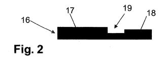
- the central region 17 is offset from the edge region 18.
- a circumferential groove 19 is formed here in the edge region 18. This groove serves to receive the impregnated and thus incompressible edge region of an MEA when pressing the BPPS / MEA structure.
- BPPs are also provided which are equipped with an integrated edge seal, provided that the central region of such a BPP arrangement is offset against its edge region.
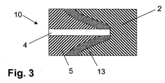
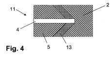
- the MEAs 10, 11 and 12 shown in FIGS. 3, 4 and 5 likewise comprise a polymer electrolyte membrane (PEM) 4 whose surfaces are provided on the one hand with a layer of cathode catalyst material and on the other hand with a layer of anode catalyst material Detail are shown.
- the PEM 4 is disposed between two gas diffusion layers (GDL) 5, which are also formed of a porous substrate. Although the GDLs 5 are flush with the PEM 4 in all three cases shown. In contrast to the embodiment shown in FIG. 1, however, the edges of the GDLs 5 are each flattened.
- the MEAs 10, 11 and 12 are each provided with an integral seal 2 made of an elastic sealing material.
- the seal 2 surrounds the edge region of the MEA 10.
- the sealing material has penetrated into the flattened regions of the GDLs 5 during the production of the seal 2, in which the edge region of the MEA 10 has also been impregnated.
- the edge region of the MEA 10 can also be compressed perpendicular to the membrane plane since the gasket 2 extending into this region and the non-impregnated GDL material can be compressed.
- the edges of the GDLs 5 are beveled with respect to the plane of the membrane at an angle of approximately 45 °.
- This MEA 11 is also equipped with an integrated seal 2, which consists of an elastic sealing material. As in the embodiment shown in Fig. 3, the sealing material has penetrated to a certain depth in the MEA material and in particular in the porous substrate of the GDLs 5. Since the edges of the GDLs 5 are bevelled with respect to the membrane plane and the impregnation 13 is formed only in a region extending parallel to these bevelled edges, also here, the edge region of the MEA 11 can be compressed perpendicular to the membrane plane, although by Impregnate resulting composite is substantially incompressible.
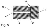
- FIG. 5 shows an inventive MEA 12 with an integrated seal 2, which does not surround the impregnated edge region, since a groove 14 is formed in this region.
- this groove 14 was only later - after the impregnation and molding of the seal 2 - - generated, so that the impregnated edge region of the GDLs 5 is formed thinner than its non-impregnated central region , It should be noted at this point that such a groove 14 does not necessarily have to extend over the entire width of the impregnated edge region.
- the MEAs 10, 11 and 12 shown in FIGS. 3, 4 and 5 can each be used in conjunction with plane-parallel bipolar plates, since here, simply by simply pressing the BPP / MEA / BPP structure, good surface contact between the PEM 4 and the GDLs 5 and between GDLs 5 and BPPs. In addition, a displacement of parts of the GDL is avoided in the flow channels of the BPPs. To improve the surface contact, however, these MEAs 10, 11 and 12 can also be used in conjunction with bipolar plates, as illustrated in FIGS. 1 and 2 and explained in connection with these figures.
Landscapes
- Life Sciences & Earth Sciences (AREA)
- Engineering & Computer Science (AREA)
- Manufacturing & Machinery (AREA)
- Sustainable Development (AREA)
- Sustainable Energy (AREA)
- Chemical & Material Sciences (AREA)
- Chemical Kinetics & Catalysis (AREA)
- Electrochemistry (AREA)
- General Chemical & Material Sciences (AREA)
- Fuel Cell (AREA)
Applications Claiming Priority (1)
| Application Number | Priority Date | Filing Date | Title |
|---|---|---|---|
| DE102004031762A DE102004031762A1 (de) | 2004-07-01 | 2004-07-01 | Brennstoffzelle |
Publications (3)
| Publication Number | Publication Date |
|---|---|
| EP1612877A2 true EP1612877A2 (fr) | 2006-01-04 |
| EP1612877A3 EP1612877A3 (fr) | 2006-08-30 |
| EP1612877B1 EP1612877B1 (fr) | 2008-05-14 |
Family
ID=35115953
Family Applications (1)
| Application Number | Title | Priority Date | Filing Date |
|---|---|---|---|
| EP05004627A Not-in-force EP1612877B1 (fr) | 2004-07-01 | 2005-03-03 | Pile à combustible |
Country Status (3)
| Country | Link |
|---|---|
| EP (1) | EP1612877B1 (fr) |
| AT (1) | ATE395722T1 (fr) |
| DE (2) | DE102004031762A1 (fr) |
Cited By (3)
| Publication number | Priority date | Publication date | Assignee | Title |
|---|---|---|---|---|
| WO2007144717A1 (fr) | 2006-06-09 | 2007-12-21 | Toyota Jidosha Kabushiki Kaisha | Pile à combustible et procédé pour sa fabrication |
| EP2131433A1 (fr) | 2008-06-05 | 2009-12-09 | Reinz-Dichtungs-Gmbh | Cellule électrochimique et procédé de sa fabrication |
| WO2011154811A1 (fr) | 2010-06-08 | 2011-12-15 | Rensselaer Polytechnic Institute | Procédé de production de cellule électrochimique |
Families Citing this family (2)
| Publication number | Priority date | Publication date | Assignee | Title |
|---|---|---|---|---|
| DE102017101954A1 (de) | 2017-02-01 | 2018-08-02 | Audi Ag | Membran-Elektroden-Anordnung und Brennstoffzellenstapel |
| CN108172843B (zh) * | 2017-12-29 | 2023-11-07 | 上海神力科技有限公司 | 一种燃料电池电堆的双极板装置 |
Citations (3)
| Publication number | Priority date | Publication date | Assignee | Title |
|---|---|---|---|---|
| DE19713250A1 (de) * | 1997-03-29 | 1998-10-15 | Ballard Power Systems | Elektrochemischer Energiewandler mit Polymerelektrolytmembran |
| US20020031698A1 (en) * | 2000-05-02 | 2002-03-14 | Honda Giken Kogyo Kabushiki Kaisha | Fuel cell having sealant for sealing a solid polymer electrolyte membrane |
| EP1372203A1 (fr) * | 2002-05-30 | 2003-12-17 | Ballard Power Systems Inc. | Assemblage membrane-électrodes pour des piles à combustible |
-
2004
- 2004-07-01 DE DE102004031762A patent/DE102004031762A1/de not_active Withdrawn
-
2005
- 2005-03-03 DE DE502005004084T patent/DE502005004084D1/de active Active
- 2005-03-03 EP EP05004627A patent/EP1612877B1/fr not_active Not-in-force
- 2005-03-03 AT AT05004627T patent/ATE395722T1/de not_active IP Right Cessation
Patent Citations (3)
| Publication number | Priority date | Publication date | Assignee | Title |
|---|---|---|---|---|
| DE19713250A1 (de) * | 1997-03-29 | 1998-10-15 | Ballard Power Systems | Elektrochemischer Energiewandler mit Polymerelektrolytmembran |
| US20020031698A1 (en) * | 2000-05-02 | 2002-03-14 | Honda Giken Kogyo Kabushiki Kaisha | Fuel cell having sealant for sealing a solid polymer electrolyte membrane |
| EP1372203A1 (fr) * | 2002-05-30 | 2003-12-17 | Ballard Power Systems Inc. | Assemblage membrane-électrodes pour des piles à combustible |
Cited By (7)
| Publication number | Priority date | Publication date | Assignee | Title |
|---|---|---|---|---|
| WO2007144717A1 (fr) | 2006-06-09 | 2007-12-21 | Toyota Jidosha Kabushiki Kaisha | Pile à combustible et procédé pour sa fabrication |
| CN101467289B (zh) * | 2006-06-09 | 2011-05-25 | 丰田自动车株式会社 | 燃料电池及其制造方法 |
| US8232023B2 (en) | 2006-06-09 | 2012-07-31 | Toyota Jidosha Kabushiki Kaisha | Fuel cell and method of manufacturing same |
| EP2131433A1 (fr) | 2008-06-05 | 2009-12-09 | Reinz-Dichtungs-Gmbh | Cellule électrochimique et procédé de sa fabrication |
| WO2009146924A1 (fr) * | 2008-06-05 | 2009-12-10 | Reinz-Dichtungs-Gmbh | Procédé de fabrication d'une pile électrochimique |
| WO2011154811A1 (fr) | 2010-06-08 | 2011-12-15 | Rensselaer Polytechnic Institute | Procédé de production de cellule électrochimique |
| US9537166B2 (en) | 2010-06-08 | 2017-01-03 | Rensselaer Polytechnic Institute | Method for the production of an electrochemical cell |
Also Published As
| Publication number | Publication date |
|---|---|
| EP1612877B1 (fr) | 2008-05-14 |
| DE102004031762A1 (de) | 2006-01-26 |
| DE502005004084D1 (de) | 2008-06-26 |
| EP1612877A3 (fr) | 2006-08-30 |
| ATE395722T1 (de) | 2008-05-15 |
Similar Documents
| Publication | Publication Date | Title |
|---|---|---|
| EP0815609B1 (fr) | Assemblage de cellules individuelles pour former une unite d'electrodes membranaires et son utilisation | |
| DE602004001520T2 (de) | Membranelektrodenbaugruppe mit integrierter dichtung | |
| EP3378117B1 (fr) | Plaque bipolaire à sections d'étanchéité asymétriques et empilement de piles à combustible muni d'une telle plaque bipolaire | |
| DE112008000004B4 (de) | Brennstoffzellenmodul, Brennstoffzelle und Verfahren zum Herstellen eines Brennstoffzellenmoduls | |
| WO2002078107A2 (fr) | Ensemble plaque terminale d'une cellule electrochimique du type a membrane electrolyte polymere | |
| DE102005007353B4 (de) | Brennstoffzelle | |
| EP3248236A1 (fr) | Unité électrochimique pour empilement de cellules élémentaires | |
| EP1608033B1 (fr) | Substrat avec joint intégré | |
| EP1759434B2 (fr) | Module membrane-electrode (mea) pour pile a combustible | |
| WO2022223657A2 (fr) | Ensemble de cellules individuelles pour un empilement de pile à combustible | |
| EP1612877B1 (fr) | Pile à combustible | |
| EP1589602B1 (fr) | Ressort de contact et pile eléctrique le contenant | |
| DE102014203150B4 (de) | Brennstoffzelle und Verfahren zur Herstellung eines Brennstoffzellenstapels | |
| DE2416094A1 (de) | Poroeses bauteil fuer mit geloesten reagenzien arbeitende brennstoffzelle in filterpressenbauweise | |
| DE102018103411A1 (de) | Brennstoffzellenendplatteneinheit und -stapel | |
| DE10233982A1 (de) | Bipolare Platte für eine Brennstoffzelle | |
| DE112004001748B4 (de) | Brennstoffzellenanordnung und Verfahren zur Herstellung | |
| DE102018212498A1 (de) | Elektrode für eine Brennstoffzelle oder einen Stapel von Brennstoffzellen | |
| DE102024104248A1 (de) | Elektrochemischer Zellenstapel | |
| WO2024110137A1 (fr) | Électrode pour un élément de batterie unique, élément de batterie unique et procédé de remplissage avec un électrolyte | |
| DE102021134243A1 (de) | Elektrochemische Einheit für eine elektrochemische Vorrichtung und elektrochemische Vorrichtung | |
| WO2024175356A1 (fr) | Ensemble membrane-électrode pour une cellule électrochimique et cellule électrochimique | |
| DE102023111278A1 (de) | Elektrochemischer Zellenstapel und Verfahren zum Betrieb eines elektrochemischen Zellenstapels | |
| WO2023227423A2 (fr) | Dispositif électrochimique et procédé de production d'un élément d'étanchéité sur une couche de diffusion de gaz d'une unité électrochimique | |
| DE102023201483A1 (de) | Membran-Elektroden-Anordnung für eine Elektrolysezelle und Verfahren zum Betreiben einer Elektrolysezelle mit einer Membran-Elektroden-Anordnung |
Legal Events
| Date | Code | Title | Description |
|---|---|---|---|
| PUAI | Public reference made under article 153(3) epc to a published international application that has entered the european phase |
Free format text: ORIGINAL CODE: 0009012 |
|
| AK | Designated contracting states |
Kind code of ref document: A2 Designated state(s): AT BE BG CH CY CZ DE DK EE ES FI FR GB GR HU IE IS IT LI LT LU MC NL PL PT RO SE SI SK TR |
|
| AX | Request for extension of the european patent |
Extension state: AL BA HR LV MK YU |
|
| PUAL | Search report despatched |
Free format text: ORIGINAL CODE: 0009013 |
|
| AK | Designated contracting states |
Kind code of ref document: A3 Designated state(s): AT BE BG CH CY CZ DE DK EE ES FI FR GB GR HU IE IS IT LI LT LU MC NL PL PT RO SE SI SK TR |
|
| AX | Request for extension of the european patent |
Extension state: AL BA HR LV MK YU |
|
| 17P | Request for examination filed |
Effective date: 20060804 |
|
| AKX | Designation fees paid |
Designated state(s): AT BE BG CH CY CZ DE DK EE ES FI FR GB GR HU IE IS IT LI LT LU MC NL PL PT RO SE SI SK TR |
|
| 17Q | First examination report despatched |
Effective date: 20070424 |
|
| GRAP | Despatch of communication of intention to grant a patent |
Free format text: ORIGINAL CODE: EPIDOSNIGR1 |
|
| GRAS | Grant fee paid |
Free format text: ORIGINAL CODE: EPIDOSNIGR3 |
|
| GRAA | (expected) grant |
Free format text: ORIGINAL CODE: 0009210 |
|
| AK | Designated contracting states |
Kind code of ref document: B1 Designated state(s): AT BE BG CH CY CZ DE DK EE ES FI FR GB GR HU IE IS IT LI LT LU MC NL PL PT RO SE SI SK TR |
|
| REG | Reference to a national code |
Ref country code: GB Ref legal event code: FG4D Free format text: NOT ENGLISH |
|
| REG | Reference to a national code |
Ref country code: CH Ref legal event code: EP |
|
| REG | Reference to a national code |
Ref country code: IE Ref legal event code: FG4D Free format text: LANGUAGE OF EP DOCUMENT: GERMAN |
|
| REF | Corresponds to: |
Ref document number: 502005004084 Country of ref document: DE Date of ref document: 20080626 Kind code of ref document: P |
|
| PG25 | Lapsed in a contracting state [announced via postgrant information from national office to epo] |
Ref country code: SI Free format text: LAPSE BECAUSE OF FAILURE TO SUBMIT A TRANSLATION OF THE DESCRIPTION OR TO PAY THE FEE WITHIN THE PRESCRIBED TIME-LIMIT Effective date: 20080514 |
|
| PG25 | Lapsed in a contracting state [announced via postgrant information from national office to epo] |
Ref country code: ES Free format text: LAPSE BECAUSE OF FAILURE TO SUBMIT A TRANSLATION OF THE DESCRIPTION OR TO PAY THE FEE WITHIN THE PRESCRIBED TIME-LIMIT Effective date: 20080825 Ref country code: FI Free format text: LAPSE BECAUSE OF FAILURE TO SUBMIT A TRANSLATION OF THE DESCRIPTION OR TO PAY THE FEE WITHIN THE PRESCRIBED TIME-LIMIT Effective date: 20080514 |
|
| NLV1 | Nl: lapsed or annulled due to failure to fulfill the requirements of art. 29p and 29m of the patents act | ||
| PG25 | Lapsed in a contracting state [announced via postgrant information from national office to epo] |
Ref country code: NL Free format text: LAPSE BECAUSE OF FAILURE TO SUBMIT A TRANSLATION OF THE DESCRIPTION OR TO PAY THE FEE WITHIN THE PRESCRIBED TIME-LIMIT Effective date: 20080514 Ref country code: PL Free format text: LAPSE BECAUSE OF FAILURE TO SUBMIT A TRANSLATION OF THE DESCRIPTION OR TO PAY THE FEE WITHIN THE PRESCRIBED TIME-LIMIT Effective date: 20080514 |
|
| PG25 | Lapsed in a contracting state [announced via postgrant information from national office to epo] |
Ref country code: IS Free format text: LAPSE BECAUSE OF FAILURE TO SUBMIT A TRANSLATION OF THE DESCRIPTION OR TO PAY THE FEE WITHIN THE PRESCRIBED TIME-LIMIT Effective date: 20080914 |
|
| REG | Reference to a national code |
Ref country code: IE Ref legal event code: FD4D |
|
| PG25 | Lapsed in a contracting state [announced via postgrant information from national office to epo] |
Ref country code: SE Free format text: LAPSE BECAUSE OF FAILURE TO SUBMIT A TRANSLATION OF THE DESCRIPTION OR TO PAY THE FEE WITHIN THE PRESCRIBED TIME-LIMIT Effective date: 20080814 Ref country code: CZ Free format text: LAPSE BECAUSE OF FAILURE TO SUBMIT A TRANSLATION OF THE DESCRIPTION OR TO PAY THE FEE WITHIN THE PRESCRIBED TIME-LIMIT Effective date: 20080514 Ref country code: DK Free format text: LAPSE BECAUSE OF FAILURE TO SUBMIT A TRANSLATION OF THE DESCRIPTION OR TO PAY THE FEE WITHIN THE PRESCRIBED TIME-LIMIT Effective date: 20080514 Ref country code: LT Free format text: LAPSE BECAUSE OF FAILURE TO SUBMIT A TRANSLATION OF THE DESCRIPTION OR TO PAY THE FEE WITHIN THE PRESCRIBED TIME-LIMIT Effective date: 20080514 Ref country code: IE Free format text: LAPSE BECAUSE OF FAILURE TO SUBMIT A TRANSLATION OF THE DESCRIPTION OR TO PAY THE FEE WITHIN THE PRESCRIBED TIME-LIMIT Effective date: 20080514 Ref country code: PT Free format text: LAPSE BECAUSE OF FAILURE TO SUBMIT A TRANSLATION OF THE DESCRIPTION OR TO PAY THE FEE WITHIN THE PRESCRIBED TIME-LIMIT Effective date: 20081014 |
|
| PG25 | Lapsed in a contracting state [announced via postgrant information from national office to epo] |
Ref country code: SK Free format text: LAPSE BECAUSE OF FAILURE TO SUBMIT A TRANSLATION OF THE DESCRIPTION OR TO PAY THE FEE WITHIN THE PRESCRIBED TIME-LIMIT Effective date: 20080514 Ref country code: RO Free format text: LAPSE BECAUSE OF FAILURE TO SUBMIT A TRANSLATION OF THE DESCRIPTION OR TO PAY THE FEE WITHIN THE PRESCRIBED TIME-LIMIT Effective date: 20080514 |
|
| PLBE | No opposition filed within time limit |
Free format text: ORIGINAL CODE: 0009261 |
|
| STAA | Information on the status of an ep patent application or granted ep patent |
Free format text: STATUS: NO OPPOSITION FILED WITHIN TIME LIMIT |
|
| 26N | No opposition filed |
Effective date: 20090217 |
|
| PG25 | Lapsed in a contracting state [announced via postgrant information from national office to epo] |
Ref country code: BG Free format text: LAPSE BECAUSE OF FAILURE TO SUBMIT A TRANSLATION OF THE DESCRIPTION OR TO PAY THE FEE WITHIN THE PRESCRIBED TIME-LIMIT Effective date: 20080814 Ref country code: EE Free format text: LAPSE BECAUSE OF FAILURE TO SUBMIT A TRANSLATION OF THE DESCRIPTION OR TO PAY THE FEE WITHIN THE PRESCRIBED TIME-LIMIT Effective date: 20080514 |
|
| PG25 | Lapsed in a contracting state [announced via postgrant information from national office to epo] |
Ref country code: IT Free format text: LAPSE BECAUSE OF FAILURE TO SUBMIT A TRANSLATION OF THE DESCRIPTION OR TO PAY THE FEE WITHIN THE PRESCRIBED TIME-LIMIT Effective date: 20080514 |
|
| BERE | Be: lapsed |
Owner name: CARL FREUDENBERG K.G. Effective date: 20090331 |
|
| PG25 | Lapsed in a contracting state [announced via postgrant information from national office to epo] |
Ref country code: MC Free format text: LAPSE BECAUSE OF NON-PAYMENT OF DUE FEES Effective date: 20090331 |
|
| REG | Reference to a national code |
Ref country code: CH Ref legal event code: PL |
|
| PG25 | Lapsed in a contracting state [announced via postgrant information from national office to epo] |
Ref country code: CH Free format text: LAPSE BECAUSE OF NON-PAYMENT OF DUE FEES Effective date: 20090331 Ref country code: LI Free format text: LAPSE BECAUSE OF NON-PAYMENT OF DUE FEES Effective date: 20090331 |
|
| PG25 | Lapsed in a contracting state [announced via postgrant information from national office to epo] |
Ref country code: BE Free format text: LAPSE BECAUSE OF NON-PAYMENT OF DUE FEES Effective date: 20090331 |
|
| PG25 | Lapsed in a contracting state [announced via postgrant information from national office to epo] |
Ref country code: AT Free format text: LAPSE BECAUSE OF NON-PAYMENT OF DUE FEES Effective date: 20090303 |
|
| PG25 | Lapsed in a contracting state [announced via postgrant information from national office to epo] |
Ref country code: GR Free format text: LAPSE BECAUSE OF FAILURE TO SUBMIT A TRANSLATION OF THE DESCRIPTION OR TO PAY THE FEE WITHIN THE PRESCRIBED TIME-LIMIT Effective date: 20080815 |
|
| PG25 | Lapsed in a contracting state [announced via postgrant information from national office to epo] |
Ref country code: LU Free format text: LAPSE BECAUSE OF NON-PAYMENT OF DUE FEES Effective date: 20090303 |
|
| PGFP | Annual fee paid to national office [announced via postgrant information from national office to epo] |
Ref country code: FR Payment date: 20110401 Year of fee payment: 7 |
|
| PG25 | Lapsed in a contracting state [announced via postgrant information from national office to epo] |
Ref country code: HU Free format text: LAPSE BECAUSE OF FAILURE TO SUBMIT A TRANSLATION OF THE DESCRIPTION OR TO PAY THE FEE WITHIN THE PRESCRIBED TIME-LIMIT Effective date: 20081115 |
|
| PGFP | Annual fee paid to national office [announced via postgrant information from national office to epo] |
Ref country code: DE Payment date: 20110411 Year of fee payment: 7 Ref country code: GB Payment date: 20110324 Year of fee payment: 7 |
|
| PG25 | Lapsed in a contracting state [announced via postgrant information from national office to epo] |
Ref country code: TR Free format text: LAPSE BECAUSE OF FAILURE TO SUBMIT A TRANSLATION OF THE DESCRIPTION OR TO PAY THE FEE WITHIN THE PRESCRIBED TIME-LIMIT Effective date: 20080514 |
|
| PG25 | Lapsed in a contracting state [announced via postgrant information from national office to epo] |
Ref country code: CY Free format text: LAPSE BECAUSE OF FAILURE TO SUBMIT A TRANSLATION OF THE DESCRIPTION OR TO PAY THE FEE WITHIN THE PRESCRIBED TIME-LIMIT Effective date: 20080514 |
|
| GBPC | Gb: european patent ceased through non-payment of renewal fee |
Effective date: 20120303 |
|
| REG | Reference to a national code |
Ref country code: FR Ref legal event code: ST Effective date: 20121130 |
|
| REG | Reference to a national code |
Ref country code: DE Ref legal event code: R119 Ref document number: 502005004084 Country of ref document: DE Effective date: 20121002 |
|
| PG25 | Lapsed in a contracting state [announced via postgrant information from national office to epo] |
Ref country code: GB Free format text: LAPSE BECAUSE OF NON-PAYMENT OF DUE FEES Effective date: 20120303 Ref country code: FR Free format text: LAPSE BECAUSE OF NON-PAYMENT OF DUE FEES Effective date: 20120402 |
|
| PG25 | Lapsed in a contracting state [announced via postgrant information from national office to epo] |
Ref country code: DE Free format text: LAPSE BECAUSE OF NON-PAYMENT OF DUE FEES Effective date: 20121002 |