EP1612877A2 - Brennstoffzelle - Google Patents
Brennstoffzelle Download PDFInfo
- Publication number
- EP1612877A2 EP1612877A2 EP05004627A EP05004627A EP1612877A2 EP 1612877 A2 EP1612877 A2 EP 1612877A2 EP 05004627 A EP05004627 A EP 05004627A EP 05004627 A EP05004627 A EP 05004627A EP 1612877 A2 EP1612877 A2 EP 1612877A2
- Authority
- EP
- European Patent Office
- Prior art keywords
- mea
- edge region
- membrane
- fuel cell
- impregnated
- Prior art date
- Legal status (The legal status is an assumption and is not a legal conclusion. Google has not performed a legal analysis and makes no representation as to the accuracy of the status listed.)
- Granted
Links
Images

Classifications
-
- H—ELECTRICITY
- H01—ELECTRIC ELEMENTS
- H01M—PROCESSES OR MEANS, e.g. BATTERIES, FOR THE DIRECT CONVERSION OF CHEMICAL ENERGY INTO ELECTRICAL ENERGY
- H01M8/00—Fuel cells; Manufacture thereof
- H01M8/02—Details
- H01M8/0202—Collectors; Separators, e.g. bipolar separators; Interconnectors
- H01M8/023—Porous and characterised by the material
-
- H—ELECTRICITY
- H01—ELECTRIC ELEMENTS
- H01M—PROCESSES OR MEANS, e.g. BATTERIES, FOR THE DIRECT CONVERSION OF CHEMICAL ENERGY INTO ELECTRICAL ENERGY
- H01M8/00—Fuel cells; Manufacture thereof
- H01M8/02—Details
- H01M8/0202—Collectors; Separators, e.g. bipolar separators; Interconnectors
- H01M8/0204—Non-porous and characterised by the material
-
- H—ELECTRICITY
- H01—ELECTRIC ELEMENTS
- H01M—PROCESSES OR MEANS, e.g. BATTERIES, FOR THE DIRECT CONVERSION OF CHEMICAL ENERGY INTO ELECTRICAL ENERGY
- H01M8/00—Fuel cells; Manufacture thereof
- H01M8/02—Details
- H01M8/0202—Collectors; Separators, e.g. bipolar separators; Interconnectors
- H01M8/0247—Collectors; Separators, e.g. bipolar separators; Interconnectors characterised by the form
-
- H—ELECTRICITY
- H01—ELECTRIC ELEMENTS
- H01M—PROCESSES OR MEANS, e.g. BATTERIES, FOR THE DIRECT CONVERSION OF CHEMICAL ENERGY INTO ELECTRICAL ENERGY
- H01M8/00—Fuel cells; Manufacture thereof
- H01M8/02—Details
- H01M8/0202—Collectors; Separators, e.g. bipolar separators; Interconnectors
- H01M8/0258—Collectors; Separators, e.g. bipolar separators; Interconnectors characterised by the configuration of channels, e.g. by the flow field of the reactant or coolant
-
- H—ELECTRICITY
- H01—ELECTRIC ELEMENTS
- H01M—PROCESSES OR MEANS, e.g. BATTERIES, FOR THE DIRECT CONVERSION OF CHEMICAL ENERGY INTO ELECTRICAL ENERGY
- H01M8/00—Fuel cells; Manufacture thereof
- H01M8/02—Details
- H01M8/0271—Sealing or supporting means around electrodes, matrices or membranes
-
- H—ELECTRICITY
- H01—ELECTRIC ELEMENTS
- H01M—PROCESSES OR MEANS, e.g. BATTERIES, FOR THE DIRECT CONVERSION OF CHEMICAL ENERGY INTO ELECTRICAL ENERGY
- H01M8/00—Fuel cells; Manufacture thereof
- H01M8/02—Details
- H01M8/0271—Sealing or supporting means around electrodes, matrices or membranes
- H01M8/0273—Sealing or supporting means around electrodes, matrices or membranes with sealing or supporting means in the form of a frame
-
- H—ELECTRICITY
- H01—ELECTRIC ELEMENTS
- H01M—PROCESSES OR MEANS, e.g. BATTERIES, FOR THE DIRECT CONVERSION OF CHEMICAL ENERGY INTO ELECTRICAL ENERGY
- H01M8/00—Fuel cells; Manufacture thereof
- H01M8/02—Details
- H01M8/0271—Sealing or supporting means around electrodes, matrices or membranes
- H01M8/0276—Sealing means characterised by their form
-
- H—ELECTRICITY
- H01—ELECTRIC ELEMENTS
- H01M—PROCESSES OR MEANS, e.g. BATTERIES, FOR THE DIRECT CONVERSION OF CHEMICAL ENERGY INTO ELECTRICAL ENERGY
- H01M8/00—Fuel cells; Manufacture thereof
- H01M8/10—Fuel cells with solid electrolytes
- H01M8/1004—Fuel cells with solid electrolytes characterised by membrane-electrode assemblies [MEA]
-
- H—ELECTRICITY
- H01—ELECTRIC ELEMENTS
- H01M—PROCESSES OR MEANS, e.g. BATTERIES, FOR THE DIRECT CONVERSION OF CHEMICAL ENERGY INTO ELECTRICAL ENERGY
- H01M8/00—Fuel cells; Manufacture thereof
- H01M8/10—Fuel cells with solid electrolytes
- H01M2008/1095—Fuel cells with polymeric electrolytes
-
- Y—GENERAL TAGGING OF NEW TECHNOLOGICAL DEVELOPMENTS; GENERAL TAGGING OF CROSS-SECTIONAL TECHNOLOGIES SPANNING OVER SEVERAL SECTIONS OF THE IPC; TECHNICAL SUBJECTS COVERED BY FORMER USPC CROSS-REFERENCE ART COLLECTIONS [XRACs] AND DIGESTS
- Y02—TECHNOLOGIES OR APPLICATIONS FOR MITIGATION OR ADAPTATION AGAINST CLIMATE CHANGE
- Y02E—REDUCTION OF GREENHOUSE GAS [GHG] EMISSIONS, RELATED TO ENERGY GENERATION, TRANSMISSION OR DISTRIBUTION
- Y02E60/00—Enabling technologies; Technologies with a potential or indirect contribution to GHG emissions mitigation
- Y02E60/30—Hydrogen technology
- Y02E60/50—Fuel cells
Definitions
- the invention relates to a fuel cell with a membrane electrode assembly (MEA), which is arranged between two bipolar plates (BPP), wherein the MEA comprises a membrane, which is arranged between at least two gas diffusion layers (GDL), the edge region of the MEA with a Sealing material is impregnated and the existing of the BPPs and the MEA structure is pressed.
- MEA membrane electrode assembly
- BPP bipolar plates
- GDL gas diffusion layers
- the invention relates to a BPP and an MEA for use in such a fuel cell.
- a membrane electrode assembly for a fuel cell comprising a polymer electrolyte membrane (PEM) having an anode catalyst layer on one side and a cathode catalyst layer on the other side.
- PEM polymer electrolyte membrane
- This PEM is arranged between an anode-side gas diffusion layer (GDL) and a cathode-side gas diffusion layer.
- GDL gas diffusion layer
- the edge area of the PEM projects beyond the GDLs and is provided with gaskets on both sides.
- the edge regions of the GDLs are impregnated with the elastomeric material of the gaskets.
- impregnation of the edge region of the MEA with the material of an integrated seal proves advantageous in several respects.
- the impregnation of the edge area of the MEA is usually made together with the seal, which can be particularly well connected to the MEA.
- the impregnation combines the individual layers of the MEA with one another and thus stabilizes their structure, in particular in the region of the membrane outlet, where weak spots otherwise occur. This stabilization or stiffening also simplifies the handling of the MEA as a whole in the subsequent assembly of the cell.
- the prerequisite for the function of a fuel cell is a surface contact between the PEM and the GDLs as well as between the GDLs and the adjacent BPPs. Therefore, the structure consisting of BPP / MEA / BPP is usually compressed, and in particular the GDLs of the MEA in the area of the active area of the PEM are to be pressed between the two BPPs.
- the impregnated edge area acts as a stopper or as a stop when pressing the BPP / MEA / BPP structure so that a surface contacting is not ensured or even improved can be. Further compression may result in parts of the GDLs being displaced into the flow channels that are in the active area, i. the median surface integrated with BPPs.
- the present invention proposes measures which can easily improve the contact between the PEM and the GDLs as well as between the GDLs and the respective adjacent BPPs of a fuel cell equipped with an impregnated edge area MEA.
- the composite of materials resulting from the impregnation of the MEA materials with the elastic seal material is substantially incompressible or at least substantially less compressible than the unimpregnated midregion of the MEA and also less than the seal formed from the seal material .
- special measures are required in order to improve the surface contact between the layers adjoining the PEM by simple compression of the BPP / MEA / BPP structure, since the incompressible edge region precludes such compression. Therefore, it is proposed to use bipolar plates instead of the commonly used bipolar plates whose center region, in which the flow field of the fuel cell is usually located, is set down against the edge region.
- the middle region can be designed to be thicker compared to the edge region.
- the active region of the MEA can easily be compressed, although the edge region of the bipolar plates rests on the incompressible edge region of the MEA.
- a peripheral groove or a shoulder for receiving the impregnated edge region of the MEA is formed in the edge region of the bipolar plates. This proves to be advantageous both with regard to a simple production of the bipolar plates and with regard to a simple assembly of the fuel cell.
- the incompressibility of the impregnated edge region of the MEA can advantageously be exploited in order to prevent the structure consisting of BPPs and MEA from being too strongly compressed.
- the edge region of the GDLs which is or is provided with an impregnation, can also be made thinner than the central region.
- the edges of the GDLs are bevelled with respect to the membrane plane or at least flattened. Since the sealing material penetrates into the MEA material only to a certain depth during the impregnation of a beveled edge area of the MEA, in this case an impregnated area is formed, which is compressible in the pressing direction, ie perpendicular to the PEM.
- the edge region of the GDLs can also be provided with a shoulder and thus made thinner than the middle region.
- the central region is then compressible at least up to the height of the impregnated edge region. If the shoulder is produced in the edge region of the GDLs prior to impregnation and molding of a seal, the seal surrounds the impregnated edge region. The paragraph can also be generated later, so that the MEA has a groove in the impregnated edge region.
- a membrane-electrode assembly (MEA) 1 with an integrated seal 2 and an impregnated edge region 3 is shown schematically.
- the MEA 1 comprises a polymer electrolyte membrane (PEM) 4, the surfaces of which are provided on the one hand with a layer of cathode catalyst material and on the other hand with a layer of anode catalyst material. These catalyst layers are not shown here.
- the PEM 4 is disposed between two gas diffusion layers (GDL) 5, which in the embodiment shown here are flush with the PEM 4 and made of a porous substrate, such as e.g. a nonwoven fabric, a fabric or paper are formed.
- the integrated seal 2 consists of an elastic sealing material. During the production of the seal 2, the edge region 3 of the MEA 1 was also impregnated. In this case, a substantially incompressible bond between the sealing material and the MEA materials, in particular the porous substrate of the GDLs 5, has formed.
- bipolar plates (BPP) 6, only one of which is shown here.
- BPP bipolar plates
- bipolar plates can also be made of other conductive materials, such as graphite or mixtures with a high graphite content.
- the central region 7 of the BPP 6 is offset against its edge region 8.
- a peripheral shoulder 9 is formed in the edge region 8, so that the middle region 7 has a greater thickness than the edge region 8 of the BPP 6.
- This structure of the BPP 6 results in the middle region of the MEA 1 being compressed more strongly than the impregnated edge region 3 the MEA 1 when a structure consisting of two BPPs 6 and the MEA 1 is pressed. In this way, good surface contact between the PEM 4 and the GDLs 5 as well as between the GDLs 5 and the BPPs 6 can be made.
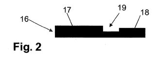
- the central region 17 is offset from the edge region 18.
- a circumferential groove 19 is formed here in the edge region 18. This groove serves to receive the impregnated and thus incompressible edge region of an MEA when pressing the BPPS / MEA structure.
- BPPs are also provided which are equipped with an integrated edge seal, provided that the central region of such a BPP arrangement is offset against its edge region.
- the MEAs 10, 11 and 12 shown in FIGS. 3, 4 and 5 likewise comprise a polymer electrolyte membrane (PEM) 4 whose surfaces are provided on the one hand with a layer of cathode catalyst material and on the other hand with a layer of anode catalyst material Detail are shown.
- the PEM 4 is disposed between two gas diffusion layers (GDL) 5, which are also formed of a porous substrate. Although the GDLs 5 are flush with the PEM 4 in all three cases shown. In contrast to the embodiment shown in FIG. 1, however, the edges of the GDLs 5 are each flattened.
- the MEAs 10, 11 and 12 are each provided with an integral seal 2 made of an elastic sealing material.
- the seal 2 surrounds the edge region of the MEA 10.
- the sealing material has penetrated into the flattened regions of the GDLs 5 during the production of the seal 2, in which the edge region of the MEA 10 has also been impregnated.
- the edge region of the MEA 10 can also be compressed perpendicular to the membrane plane since the gasket 2 extending into this region and the non-impregnated GDL material can be compressed.
- the edges of the GDLs 5 are beveled with respect to the plane of the membrane at an angle of approximately 45 °.
- This MEA 11 is also equipped with an integrated seal 2, which consists of an elastic sealing material. As in the embodiment shown in Fig. 3, the sealing material has penetrated to a certain depth in the MEA material and in particular in the porous substrate of the GDLs 5. Since the edges of the GDLs 5 are bevelled with respect to the membrane plane and the impregnation 13 is formed only in a region extending parallel to these bevelled edges, also here, the edge region of the MEA 11 can be compressed perpendicular to the membrane plane, although by Impregnate resulting composite is substantially incompressible.
- FIG. 5 shows an inventive MEA 12 with an integrated seal 2, which does not surround the impregnated edge region, since a groove 14 is formed in this region.
- this groove 14 was only later - after the impregnation and molding of the seal 2 - - generated, so that the impregnated edge region of the GDLs 5 is formed thinner than its non-impregnated central region , It should be noted at this point that such a groove 14 does not necessarily have to extend over the entire width of the impregnated edge region.
- the MEAs 10, 11 and 12 shown in FIGS. 3, 4 and 5 can each be used in conjunction with plane-parallel bipolar plates, since here, simply by simply pressing the BPP / MEA / BPP structure, good surface contact between the PEM 4 and the GDLs 5 and between GDLs 5 and BPPs. In addition, a displacement of parts of the GDL is avoided in the flow channels of the BPPs. To improve the surface contact, however, these MEAs 10, 11 and 12 can also be used in conjunction with bipolar plates, as illustrated in FIGS. 1 and 2 and explained in connection with these figures.
Landscapes
- Life Sciences & Earth Sciences (AREA)
- Engineering & Computer Science (AREA)
- Manufacturing & Machinery (AREA)
- Sustainable Development (AREA)
- Sustainable Energy (AREA)
- Chemical & Material Sciences (AREA)
- Chemical Kinetics & Catalysis (AREA)
- Electrochemistry (AREA)
- General Chemical & Material Sciences (AREA)
- Fuel Cell (AREA)
Abstract
Description
- Die Erfindung betrifft eine Brennstoffzelle mit einer Membran-Elektroden-Anordnung (MEA), die zwischen zwei Bipolarplatten (BPP) angeordnet ist, wobei die MEA eine Membran umfasst, die zwischen mindestens zwei Gasdiffusionslagen (GDL) angeordnet ist, der Randbereich der MEA mit einem Dichtungsmaterial imprägniert ist und der aus den BPPs und der MEA bestehende Aufbau verpresst ist.
- Ferner betrifft die Erfindung eine BPP und eine MEA zur Verwendung in einer solchen Brennstoffzelle.
- In der internationalen Patentanmeldung WO 03/096456 wird eine Membran-Elektroden-Anordnung für eine Brennstoffzelle beschrieben, die eine Polymerelektrolytmembran (PEM) mit einer Anodenkatalysatorschicht auf der einen Seite und einer Kathodenkatalysatorschicht auf der anderen Seite umfasst. Diese PEM ist zwischen einer anodenseitigen Gasdiffusionslage (GDL) und einer kathodenseitigen Gasdiffusionslage angeordnet. Der Randbereich der PEM ragt über die GDLs hinaus und ist beidseitig mit Dichtungen versehen. Außerdem sind die Randbereiche der GDLs mit dem elastomeren Material der Dichtungen imprägniert.
- Eine derartige Imprägnierung des Randbereichs der MEA mit dem Material einer integrierten Dichtung erweist sich in mehrerlei Hinsicht als vorteilhaft. Die Imprägnierung des Randbereichs der MEA wird in der Regel zusammen mit der Dichtung hergestellt, die dadurch besonders gut an die MEA angebunden werden kann. Zudem verbindet die Imprägnierung die einzelnen Lagen der MEA miteinander und stabilisiert so deren Aufbau, insbesondere im Bereich des Membranaustritts, wo ansonsten Schwachstellen auftreten. Durch diese Stabilisierung bzw. Versteifung vereinfacht sich auch das Handling der MEA insgesamt bei der anschließenden Assemblierung der Zelle.
- Die Verwendung der aus der internationalen Patentanmeldung WO 03/096456 bekannten MEA mit einer Imprägnierung im Randbereich erweist sich aber in der Praxis als problematisch, da das ansonsten elastomere Dichtungsmaterial in Verbindung mit dem Material der GDLs in der Regel einen weitgehend inkompressiblen Verbund bildet.
- Voraussetzung für die Funktion einer Brennstoffzelle ist eine flächige Kontaktierung zwischen der PEM und den GDLs sowie zwischen den GDLs und den jeweils angrenzenden BPPs. Deshalb wird der aus BPP/MEA/BPP bestehende Aufbau üblicherweise zusammengedrückt, wobei insbesondere die GDLs der MEA im Bereich der aktiven Fläche der PEM zwischen den beiden BPPs verpresst werden sollen. Wird jedoch eine MEA verwendet, wie sie in der internationalen Patentanmeldung WO 03/096456 beschrieben ist, so wirkt der imprägnierte Randbereich beim Verpressen des BPP/MEA/BPP-Aufbaus als Stopper bzw. als Anschlag, so dass eine Flächenkontaktierung nicht gewährleistet oder gar verbessert werden kann. Ein weiteres Verpressen kann dazu führen, dass Teile der GDLs in die Fließkanäle verdrängt werden, die in der aktiven Fläche, d.h. der Mittelfläche, der BPPs integriert sind.
- Mit der vorliegenden Erfindung werden Maßnahmen vorgeschlagen, durch die sich die Kontaktierung zwischen der PEM und den GDLs sowie zwischen den GDLs und den jeweils angrenzenden BPPs einer Brennstoffzelle, die mit einer MEA mit imprägniertem Randbereich ausgestattet ist, einfach verbessern lässt.
- Dies wird erfindungsgemäß dadurch erreicht, dass der Mittelbereich mindestens einer BPP gegen deren Randbereich abgesetzt ist, so dass der Mittelbereich der MEA stärker komprimiert wird als der imprägnierte Randbereich der MEA.
- Zunächst ist erkannt worden, dass der Materialverbund, der bei der Imprägnierung der MEA-Materialien mit dem elastischen Dichtungsmaterial entsteht, weitgehend inkompressibel ist oder sich zumindest wesentlich schlechter komprimieren lässt als der nicht imprägnierte Mittelbereich der MEA und auch schlechter als die aus dem Dichtungsmaterial gebildete Dichtung. Davon ausgehend ist erfindungsgemäß erkannt worden, dass besondere Maßnahmen erforderlich sind, um die Flächenkontaktierung zwischen den an die PEM angrenzenden Schichten durch eine einfache Verpressung des BPP/MEA/BPP-Aufbaus zu verbessern, da der inkompressible Randbereich einer solchen Verpressung entgegensteht. Deshalb wird vorgeschlagen, an Stelle der üblicherweise verwendeten planparallelen Bipolarplatten Bipolarplatten zu verwenden, deren Mittelbereich, in dem sich üblicherweise das Flow Field der Brennstoffzelle befindet, gegen den Randbereich abgesetzt ist. Beispielsweise kann der Mittelbereich dazu im Vergleich zum Randbereich dicker ausgebildet sein. Mit Hilfe derartiger Bipolarplatten kann der aktive Bereich der MEA einfach zusammengedrückt werden, obwohl der Randbereich der Bipolarplatten auf dem inkompressiblen Randbereich der MEA aufsitzt.
- In einer vorteilhaften Variante der Erfindung ist im Randbereich der Bipolarplatten eine umlaufende Nut oder ein Absatz zur Aufnahme des imprägnierten Randbereichs der MEA ausgebildet. Dies erweist sich sowohl im Hinblick auf eine einfache Fertigung der Bipolarplatten als vorteilhaft als auch im Hinblick auf eine einfache Assemblierung der Brennstoffzelle.
- Bei Verwendung von erfindungsgemäßen BPPs, wie sie voranstehend beschrieben sind, kann die Inkompressibilität des imprägnierten Randbereichs der MEA in vorteilhafter Weise ausgenutzt werden, um zu verhindern, dass der aus BPPs und MEA bestehende Aufbau zu stark verpresst wird. Dazu werden die BPPs und insbesondere der Absatz zwischen Mittelbereich und Randbereich so dimensioniert, dass der imprägnierte Randbereich der MEA als Stopper, also als Anschlag beim Verpressen fungiert.
- Alternativ oder auch ergänzend zu der voranstehend beschriebenen Konfektionierung der Bipolarplatten kann auch der Randbereich der GDLs, der mit einer Imprägnierung versehen ist bzw. wird, dünner ausgebildet sein als der Mittelbereich. In einer besonders vorteilhaften Variante sind die Ränder der GDLs bzgl. der Membranebene abgeschrägt oder zumindest abgeflacht. Da das Dichtungsmaterial bei der Imprägnierung eines abgeschrägten Randbereichs der MEA nur bis zu einer bestimmten Tiefe in das MEA-Material eindringt, bildet sich in diesem Fall ein imprägnierter Bereich aus, der in Verpressrichtung, also senkrecht zur PEM, komprimierbar ist. Der Randbereich der GDLs kann aber auch mit einem Absatz versehen werden und dadurch dünner als der Mittelbereich ausgebildet werden. Der Mittelbereich ist dann zumindest bis zur Höhe des imprägnierten Randbereichs komprimierbar. Wird der Absatz im Randbereich der GDLs vor dem Imprägnieren und Anformen einer Dichtung erzeugt, so umgreift die Dichtung den imprägnierten Randbereich. Der Absatz kann aber auch nachträglich erzeugt werden, so dass die MEA eine Nut im imprägnierten Randbereich aufweist.
- Wie bereits voranstehend erörtert, gibt es verschiedene Möglichkeiten, die Lehre der vorliegenden Erfindung in vorteilhafter Weise auszugestalten und weiterzubilden. Dazu wird einerseits auf die den unabhängigen Patentansprüchen nachgeordneten Patentansprüche und andererseits auf die nachfolgende Beschreibung mehrerer Ausführungsbeispiele der Erfindung anhand der Zeichnungen verwiesen.
- Fig. 1
- zeigt eine Schnittdarstellung durch den Randabschnitt einer MEA und einer ersten erfindungsgemäßen BPP vor dem Verpressen,
- Fig. 2
- zeigt eine Schnittdarstellung durch den Randabschnitt einer zweiten erfindungsgemäßen BPP,
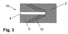
- Fig. 3
- zeigt eine Schnittdarstellung durch den Randabschnitt einer erfindungsgemäßen ersten MEA mit abgeflachten GDLs.
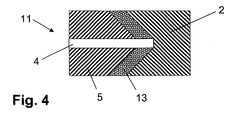
- Fig. 4
- zeigt eine Schnittdarstellung durch den Randabschnitt einer erfindungsgemäßen zweiten MEA mit abgeschrägten GDLs.
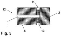
- Fig. 5
- zeigt eine Schnittdarstellung durch den Randabschnitt einer erfindungsgemäßen dritten MEA mit einer Nut im imprägnierten Randbereich.
- In Fig. 1 ist eine Membran-Elektroden-Anordnung (MEA) 1 mit einer integrierten Dichtung 2 und einem imprägnierten Randbereich 3 schematisch dargestellt. Die MEA 1 umfasst eine Polymerelektrolytmembran (PEM) 4, deren Oberflächen einerseits mit einer Schicht aus Kathodenkatalysatormaterial und andererseits mit einer Schicht aus Anodenkatalysatormaterial versehen sind. Diese Katalysatorschichten sind hier nicht dargestellt. Die PEM 4 ist zwischen zwei Gas-Diffusions-Lagen (GDL) 5 angeordnet, die im hier dargestellten Ausführungsbeispiel bündig mit der PEM 4 abschließen und aus einem porösen Substrat, wie z.B. einem Vliesstoff, einem Gewebe oder Papier, gebildet sind. Die integrierte Dichtung 2 besteht aus einem elastischen Dichtungsmaterial. Bei der Herstellung der Dichtung 2 wurde auch der Randbereich 3 der MEA 1 imprägniert. Dabei hat sich ein im wesentlichen inkompressibler Verbund zwischen dem Dichtungsmaterial und den MEA-Materialien, insbesondere dem porösen Substrat der GDLs 5, gebildet.
- Die MEA 1 wird zwischen zwei Bipolarplatten (BPP) 6 angeordnet, von denen hier nur eine dargestellt ist. Dabei kann es sich beispielsweise um Metallbleche handeln. Bipolarplatten können aber auch aus anderen leitfähigen Materialien hergestellt werden, wie z.B. aus Graphit oder Mischungen mit hohem Graphitanteil.
- Erfindungsgemäß ist der Mittelbereich 7 der BPP 6 gegen deren Randbereich 8 abgesetzt. Dazu ist im Randbereich 8 ein umlaufender Absatz 9 ausgebildet, so dass der Mittelbereich 7 eine größere Dicke aufweist als der Randbereich 8 der BPP 6. Diese Struktur der BPP 6 führt dazu, dass der Mittelbereich der MEA 1 stärker komprimiert wird als der imprägnierte Randbereich 3 der MEA 1, wenn ein aus zwei BPPs 6 und der MEA 1 bestehender Aufbau verpresst wird. Auf diese Weise kann ein guter Flächenkontakt zwischen der PEM 4 und den GDLs 5 sowie zwischen den GDLs 5 und den BPPs 6 hergestellt werden.
- Auch bei der in Fig. 2 dargestellten BPP 16 ist der Mittelbereich 17 gegen den Randbereich 18 abgesetzt. Dazu ist hier im Randbereich 18 eine umlaufende Nut 19 ausgebildet. Diese Nut dient zur Aufnahme des imprägnierten und dadurch inkompressiblen Randbereichs einer MEA beim Verpressen des BPPS/MEA-Aufbaus.
- An dieser Stelle sei angemerkt, dass im Rahmen der hier in Rede stehenden Erfindung auch BPPs liegen, die mit einer integrierten Randdichtung ausgestattet sind, sofern der Mittelbereich einer solchen BPP-Anordnung gegen deren Randbereich abgesetzt ist.
- Die in den Figuren 3, 4 und 5 dargestellten MEAs 10, 11 und 12 umfassen ebenfalls eine Polymerelektrolytmembran (PEM) 4, deren Oberflächen einerseits mit einer Schicht aus Kathodenkatalysatormaterial und andererseits mit einer Schicht aus Anodenkatalysatormaterial versehen sind, wobei diese Katalysatorschichten auch hier nicht im Detail dargestellt sind. Die PEM 4 ist zwischen zwei Gas-Diffusions-Lagen (GDL) 5 angeordnet, die ebenfalls aus einem porösen Substrat gebildet sind. Zwar schließen die GDLs 5 in allen drei dargestellten Fällen bündig mit der PEM 4 ab. Im Unterschied zu dem in Fig. 1 dargestellten Ausführungsbeispiel sind die Ränder der GDLs 5 jedoch jeweils abgeflacht. Die MEAs 10, 11 und 12 sind jeweils mit einer integrierten Dichtung 2 ausgestattet, die aus einem elastischen Dichtungsmaterial besteht.
- In dem in Fig. 3 dargestellten Ausführungsbeispiel umgreift die Dichtung 2 den Randbereich der MEA 10. Das Dichtungsmaterial ist hier bei der Herstellung der Dichtung 2, bei der auch der Randbereich der MEA 10 imprägniert worden ist, in die abgeflachten Bereiche der GDLs 5 eingedrungen. Obwohl der dabei entstandene Verbund im wesentlichen inkompressibel ist, lässt sich der Randbereich der MEA 10 hier auch senkrecht zur Membranebene komprimieren, da sich die bis in diesen Bereich erstreckende Dichtung 2 und das nicht imprägnierte GDL-Material komprimieren lassen.
- Bei der in Fig. 4 dargestellten Variante einer erfindungsgemäßen MEA 11 sind die Ränder der GDLs 5 bzgl. der Membranebene in einem Winkel von ca. 45° abgeschrägt. Auch diese MEA 11 ist mit einer integrierten Dichtung 2 ausgestattet, die aus einem elastischen Dichtungsmaterial besteht. Wie bei dem in Fig. 3 dargestellten Ausführungsbeispiel ist das Dichtungsmaterial bis zu einer bestimmten Tiefe in das MEA-Material und insbesondere in das poröse Substrat der GDLs 5 eingedrungen. Da die Ränder der GDLs 5 bzgl. der Membranebene abgeschrägt sind und die Imprägnierung 13 nur in einem Bereich ausgebildet ist, der sich parallel zu diesen abgeschrägten Rändern erstreckt, lässt sich auch hier der Randbereich der MEA 11 senkrecht zur Membranebene komprimieren, obwohl der durch das Imprägnieren entstandene Verbund im wesentlichen inkompressibel ist.
- Im Unterschied zu den in den Figuren 3 und 4 dargestellten Ausführungsbeispielen zeigt Fig. 5 eine erfindungsgemäße MEA 12 mit einer integrierten Dichtung 2, die den imprägnierten Randbereich nicht umgreift, da in diesem Bereich eine Nut 14 ausgebildet ist. Ausgehend von einer MEA, wie sie in Fig. 1 dargestellt ist, wurde diese Nut 14 erst nachträglich - nach dem Imprägnieren und Anformen der Dichtung 2 - erzeugt, so dass der imprägnierte Randbereich der GDLs 5 im Ergebnis dünner ausgebildet ist als deren nicht imprägnierter Mittelbereich. An dieser Stelle sei angemerkt, dass sich eine solche Nut 14 nicht zwangsläufig über die gesamte Breite des imprägnierten Randbereichs erstrecken muss.
- Die in den Figuren 3, 4 und 5 dargestellten MEAs 10, 11 und 12 können jeweils in Verbindung mit planparallelen Bipolarplatten verwendet werden, da hier schon allein durch einfaches Verpressen des BPP/MEA/BPP-Aufbaus ein guter Flächenkontakt zwischen der PEM 4 und den GDLs 5 sowie zwischen den GDLs 5 und den BPPs hergestellt werden kann. Außerdem wird so eine Verdrängung von Teilen der GDL in die Fließkanäle der BPPs vermieden. Zur Verbesserung des Flächenkontakts können diese MEAs 10, 11 und 12 aber auch in Verbindung mit Bipolarplatten verwendet werden, wie sie in den Figuren 1 und 2 dargestellt und in Verbindung mit diesen Figuren erläutert sind.
Claims (16)
- Brennstoffzelle mit einer Membran-Elektroden-Anordnung (MEA) (1), die zwischen zwei Bipolarplatten (BPP) (6) angeordnet ist, wobei- die MEA (1) eine Membran (4) umfasst, die zwischen mindestens zwei Gasdiffusionslagen (GDL) (5) angeordnet ist,- der Randbereich (3) der MEA (1) mit einem Dichtungsmaterial imprägniert ist und- der aus den BPPs (6) und der MEA (1) bestehende Aufbau verpresst ist,dadurch gekennzeichnet, dass der Mittelbereich (7) mindestens einer BPP (6) gegen deren Randbereich (8) abgesetzt ist, so dass der Mittelbereich der MEA (1) stärker komprimiert wird als der imprägnierte Randbereich (3) der MEA (1).
- Brennstoffzelle nach Anspruch 1, dadurch gekennzeichnet, dass der Mittelbereich (7) der BPP (6) eine größere Dicke aufweist als deren Randbereich (8).
- Brennstoffzelle nach einem der Ansprüche 1 oder 2, dadurch gekennzeichnet, dass im Randbereich (18) der BPP (16) eine umlaufende Nut (19) zur Aufnahme des imprägnierten Randbereichs der MEA ausgebildet ist.
- Brennstoffzelle nach einem der Ansprüche 1 bis 3, dadurch gekennzeichnet, dass der imprägnierte Randbereich (3) der MEA (1) als Stopper fungiert, der ein Überpressen des aus den BPPs (6) und der MEA (1) bestehenden Aufbaus verhindert.
- Brennstoffzelle nach einem der Ansprüche 1 bis 4, dadurch gekennzeichnet, dass die MEA (1; 10) mit einer integrierten Dichtung (2) versehen ist, die über den imprägnierten Randbereich (3) angebunden ist.
- Bipolarplatte (6; 16), insbesondere zur Verwendung in einer Brennstoffzelle nach einem der Ansprüche 1 bis 5, dadurch gekennzeichnet, dass der Mittelbereich (7) gegen den Randbereich (8) abgesetzt ist.
- Bipolarplatte (6) nach Anspruch 6, dadurch gekennzeichnet, dass der Mittelbereich (7) eine größere Dicke aufweist als der Randbereich (8).
- Bipolarplatte (16) nach einem der Ansprüche 6 oder 7, dadurch gekennzeichnet, dass im Randbereich (18) eine umlaufende Nut (19) ausgebildet ist.
- Brennstoffzelle mit einer Membran-Elektroden-Anordnung (MEA) (10), die zwischen zwei Bipolarplatten (BPP) angeordnet ist, wobei- die MEA (10) eine Membran (4) umfasst, die zwischen mindestens zwei Gasdiffusionslagen (GDL) (5) angeordnet ist,- der Randbereich der MEA (10) mit einem Dichtungsmaterial imprägniert ist und- der aus den BPPs und der MEA (10) bestehende Aufbau verpresst ist, insbesondere nach einem der Ansprüche 1 bis 4, dadurch gekennzeichnet, dass der Randbereich der GDLs dünner ausgebildet ist als deren Mittelbereich.
- Brennstoffzelle nach Anspruch 9, dadurch gekennzeichnet, dass im Randbereich der GDLs ein Absatz ausgebildet ist.
- Brennstoffzelle nach Anspruch 9, dadurch gekennzeichnet, dass der Rand der GDLs (5) bzgl. der Membranebene abgeflacht und insbesondere abgeschrägt ist, so dass der Randbereich der MEA (10) senkrecht zur Membranebene komprimierbar ist.
- Membran-Elektroden-Anordnung (10; 11; 12) mit mindestens zwei GasDiffusionslagen (GDL) (5) und einer Membran (4), die zwischen den GDLs angeordnet ist, und mit einer Imprägnierung (13) im Randbereich, insbesondere zur Verwendung in einer Brennstoffzelle nach einem der Ansprüche 9 bis 11, dadurch gekennzeichnet, dass der Randbereich der GDLs (5) dünner ausgebildet ist als deren Mittelbereich.
- Membran-Elektroden-Anordnung (10; 11) nach Anspruch 12, dadurch gekennzeichnet, dass der Rand der GDLs (5) bzgl. der Membranebene abgeflacht und insbesondere abgeschrägt ist, so dass der Randbereich der MEA (10; 11) senkrecht zur Membranebene komprimierbar ist.
- Membran-Elektroden-Anordnung (12) nach Anspruch 12, dadurch gekennzeichnet, dass im Randbereich der GDLs (5) ein Absatz ausgebildet ist.
- Membran-Elektroden-Anordnung (10; 11; 12) nach einem der Ansprüche 12 bis 14, dadurch gekennzeichnet, dass über die Imprägnierung (13) eine Dichtung (2) angebunden ist.
- Membran-Elektroden-Anordnung (10; 11; 12) nach Anspruch 15, dadurch gekennzeichnet, dass die Dichtung (2) den imprägnierten Randbereich zumindest teilweise umgreift.
Applications Claiming Priority (1)
| Application Number | Priority Date | Filing Date | Title |
|---|---|---|---|
| DE102004031762A DE102004031762A1 (de) | 2004-07-01 | 2004-07-01 | Brennstoffzelle |
Publications (3)
| Publication Number | Publication Date |
|---|---|
| EP1612877A2 true EP1612877A2 (de) | 2006-01-04 |
| EP1612877A3 EP1612877A3 (de) | 2006-08-30 |
| EP1612877B1 EP1612877B1 (de) | 2008-05-14 |
Family
ID=35115953
Family Applications (1)
| Application Number | Title | Priority Date | Filing Date |
|---|---|---|---|
| EP05004627A Not-in-force EP1612877B1 (de) | 2004-07-01 | 2005-03-03 | Brennstoffzelle |
Country Status (3)
| Country | Link |
|---|---|
| EP (1) | EP1612877B1 (de) |
| AT (1) | ATE395722T1 (de) |
| DE (2) | DE102004031762A1 (de) |
Cited By (3)
| Publication number | Priority date | Publication date | Assignee | Title |
|---|---|---|---|---|
| WO2007144717A1 (en) | 2006-06-09 | 2007-12-21 | Toyota Jidosha Kabushiki Kaisha | Fuel cell and method of manufacturing same |
| EP2131433A1 (de) | 2008-06-05 | 2009-12-09 | Reinz-Dichtungs-Gmbh | Elektrochemische Zelle und Verfahren zur ihrer Herstellung |
| WO2011154811A1 (en) | 2010-06-08 | 2011-12-15 | Rensselaer Polytechnic Institute | Method for the production of an electrochemical cell |
Families Citing this family (2)
| Publication number | Priority date | Publication date | Assignee | Title |
|---|---|---|---|---|
| DE102017101954A1 (de) | 2017-02-01 | 2018-08-02 | Audi Ag | Membran-Elektroden-Anordnung und Brennstoffzellenstapel |
| CN108172843B (zh) * | 2017-12-29 | 2023-11-07 | 上海神力科技有限公司 | 一种燃料电池电堆的双极板装置 |
Citations (3)
| Publication number | Priority date | Publication date | Assignee | Title |
|---|---|---|---|---|
| DE19713250A1 (de) * | 1997-03-29 | 1998-10-15 | Ballard Power Systems | Elektrochemischer Energiewandler mit Polymerelektrolytmembran |
| US20020031698A1 (en) * | 2000-05-02 | 2002-03-14 | Honda Giken Kogyo Kabushiki Kaisha | Fuel cell having sealant for sealing a solid polymer electrolyte membrane |
| EP1372203A1 (de) * | 2002-05-30 | 2003-12-17 | Ballard Power Systems Inc. | Membranelektrodeneinheit für Brennstoffzellen |
-
2004
- 2004-07-01 DE DE102004031762A patent/DE102004031762A1/de not_active Withdrawn
-
2005
- 2005-03-03 EP EP05004627A patent/EP1612877B1/de not_active Not-in-force
- 2005-03-03 AT AT05004627T patent/ATE395722T1/de not_active IP Right Cessation
- 2005-03-03 DE DE502005004084T patent/DE502005004084D1/de active Active
Patent Citations (3)
| Publication number | Priority date | Publication date | Assignee | Title |
|---|---|---|---|---|
| DE19713250A1 (de) * | 1997-03-29 | 1998-10-15 | Ballard Power Systems | Elektrochemischer Energiewandler mit Polymerelektrolytmembran |
| US20020031698A1 (en) * | 2000-05-02 | 2002-03-14 | Honda Giken Kogyo Kabushiki Kaisha | Fuel cell having sealant for sealing a solid polymer electrolyte membrane |
| EP1372203A1 (de) * | 2002-05-30 | 2003-12-17 | Ballard Power Systems Inc. | Membranelektrodeneinheit für Brennstoffzellen |
Cited By (7)
| Publication number | Priority date | Publication date | Assignee | Title |
|---|---|---|---|---|
| WO2007144717A1 (en) | 2006-06-09 | 2007-12-21 | Toyota Jidosha Kabushiki Kaisha | Fuel cell and method of manufacturing same |
| CN101467289B (zh) * | 2006-06-09 | 2011-05-25 | 丰田自动车株式会社 | 燃料电池及其制造方法 |
| US8232023B2 (en) | 2006-06-09 | 2012-07-31 | Toyota Jidosha Kabushiki Kaisha | Fuel cell and method of manufacturing same |
| EP2131433A1 (de) | 2008-06-05 | 2009-12-09 | Reinz-Dichtungs-Gmbh | Elektrochemische Zelle und Verfahren zur ihrer Herstellung |
| WO2009146924A1 (en) * | 2008-06-05 | 2009-12-10 | Reinz-Dichtungs-Gmbh | Method for the production of an electrochemical cell |
| WO2011154811A1 (en) | 2010-06-08 | 2011-12-15 | Rensselaer Polytechnic Institute | Method for the production of an electrochemical cell |
| US9537166B2 (en) | 2010-06-08 | 2017-01-03 | Rensselaer Polytechnic Institute | Method for the production of an electrochemical cell |
Also Published As
| Publication number | Publication date |
|---|---|
| EP1612877A3 (de) | 2006-08-30 |
| EP1612877B1 (de) | 2008-05-14 |
| ATE395722T1 (de) | 2008-05-15 |
| DE102004031762A1 (de) | 2006-01-26 |
| DE502005004084D1 (de) | 2008-06-26 |
Similar Documents
| Publication | Publication Date | Title |
|---|---|---|
| EP1608033B1 (de) | Substrat mit integrierter Dichtung | |
| EP0815609B1 (de) | Zusammenfassung von einzelzellen zu einer membranelektroden-einheit und deren verwendung | |
| DE602004001520T2 (de) | Membranelektrodenbaugruppe mit integrierter dichtung | |
| DE102005007353B4 (de) | Brennstoffzelle | |
| EP1759434B2 (de) | Membran-elektroden-modul (mea) für eine brennstoffzelle | |
| EP1374328B1 (de) | Endplattenanordnung einer elektrochemischen zelle der polymerelektrolytmembranbauart | |
| DE112008000004B4 (de) | Brennstoffzellenmodul, Brennstoffzelle und Verfahren zum Herstellen eines Brennstoffzellenmoduls | |
| EP3378117B1 (de) | Bipolarplatte mit asymmetrischen dichtungsabschnitten, sowie brennstoffzellenstapel mit einer solchen | |
| EP1612877B1 (de) | Brennstoffzelle | |
| EP3248236A1 (de) | Elektrochemische einheit für einen brennstoffzellenstapel | |
| DE102004022969A1 (de) | Brennstoffzelle | |
| EP1589602B1 (de) | Kontaktfederblech und elektrochemische Batterie mit einem derartigen Kontaktfederblech | |
| DE2416094A1 (de) | Poroeses bauteil fuer mit geloesten reagenzien arbeitende brennstoffzelle in filterpressenbauweise | |
| DE10233982B4 (de) | Bipolare Platte für eine Brennstoffzelle und Brennstoffzellenstapel | |
| DE102018103411A1 (de) | Brennstoffzellenendplatteneinheit und -stapel | |
| DE102014203150B4 (de) | Brennstoffzelle und Verfahren zur Herstellung eines Brennstoffzellenstapels | |
| DE112004001748B4 (de) | Brennstoffzellenanordnung und Verfahren zur Herstellung | |
| DE102007025479A1 (de) | Einzel-Brennstoffzelle für einen Brennstoffzellen-Stapel | |
| DE102018212498A1 (de) | Elektrode für eine Brennstoffzelle oder einen Stapel von Brennstoffzellen | |
| DE102021203983A1 (de) | Einzelzellanordnung für einen Brennstoffzellenstapel | |
| DE102022123492A1 (de) | Fluidzelle eines Energiespeichers | |
| WO2023227423A2 (de) | Elektrochemische vorrichtung und verfahren zum erzeugen eines dichtelements an einer gasdiffusionslage einer elektrochemischen einheit | |
| DE102021134243A1 (de) | Elektrochemische Einheit für eine elektrochemische Vorrichtung und elektrochemische Vorrichtung | |
| WO2024110137A1 (de) | Elektrode für eine batterieeinzelzelle, batterieeinzelzelle und verfahren zum befüllen mit elektrolyt | |
| WO2022238523A1 (de) | Strömungsfeld und separatorplatte |
Legal Events
| Date | Code | Title | Description |
|---|---|---|---|
| PUAI | Public reference made under article 153(3) epc to a published international application that has entered the european phase |
Free format text: ORIGINAL CODE: 0009012 |
|
| AK | Designated contracting states |
Kind code of ref document: A2 Designated state(s): AT BE BG CH CY CZ DE DK EE ES FI FR GB GR HU IE IS IT LI LT LU MC NL PL PT RO SE SI SK TR |
|
| AX | Request for extension of the european patent |
Extension state: AL BA HR LV MK YU |
|
| PUAL | Search report despatched |
Free format text: ORIGINAL CODE: 0009013 |
|
| AK | Designated contracting states |
Kind code of ref document: A3 Designated state(s): AT BE BG CH CY CZ DE DK EE ES FI FR GB GR HU IE IS IT LI LT LU MC NL PL PT RO SE SI SK TR |
|
| AX | Request for extension of the european patent |
Extension state: AL BA HR LV MK YU |
|
| 17P | Request for examination filed |
Effective date: 20060804 |
|
| AKX | Designation fees paid |
Designated state(s): AT BE BG CH CY CZ DE DK EE ES FI FR GB GR HU IE IS IT LI LT LU MC NL PL PT RO SE SI SK TR |
|
| 17Q | First examination report despatched |
Effective date: 20070424 |
|
| GRAP | Despatch of communication of intention to grant a patent |
Free format text: ORIGINAL CODE: EPIDOSNIGR1 |
|
| GRAS | Grant fee paid |
Free format text: ORIGINAL CODE: EPIDOSNIGR3 |
|
| GRAA | (expected) grant |
Free format text: ORIGINAL CODE: 0009210 |
|
| AK | Designated contracting states |
Kind code of ref document: B1 Designated state(s): AT BE BG CH CY CZ DE DK EE ES FI FR GB GR HU IE IS IT LI LT LU MC NL PL PT RO SE SI SK TR |
|
| REG | Reference to a national code |
Ref country code: GB Ref legal event code: FG4D Free format text: NOT ENGLISH |
|
| REG | Reference to a national code |
Ref country code: CH Ref legal event code: EP |
|
| REG | Reference to a national code |
Ref country code: IE Ref legal event code: FG4D Free format text: LANGUAGE OF EP DOCUMENT: GERMAN |
|
| REF | Corresponds to: |
Ref document number: 502005004084 Country of ref document: DE Date of ref document: 20080626 Kind code of ref document: P |
|
| PG25 | Lapsed in a contracting state [announced via postgrant information from national office to epo] |
Ref country code: SI Free format text: LAPSE BECAUSE OF FAILURE TO SUBMIT A TRANSLATION OF THE DESCRIPTION OR TO PAY THE FEE WITHIN THE PRESCRIBED TIME-LIMIT Effective date: 20080514 |
|
| PG25 | Lapsed in a contracting state [announced via postgrant information from national office to epo] |
Ref country code: ES Free format text: LAPSE BECAUSE OF FAILURE TO SUBMIT A TRANSLATION OF THE DESCRIPTION OR TO PAY THE FEE WITHIN THE PRESCRIBED TIME-LIMIT Effective date: 20080825 Ref country code: FI Free format text: LAPSE BECAUSE OF FAILURE TO SUBMIT A TRANSLATION OF THE DESCRIPTION OR TO PAY THE FEE WITHIN THE PRESCRIBED TIME-LIMIT Effective date: 20080514 |
|
| NLV1 | Nl: lapsed or annulled due to failure to fulfill the requirements of art. 29p and 29m of the patents act | ||
| PG25 | Lapsed in a contracting state [announced via postgrant information from national office to epo] |
Ref country code: NL Free format text: LAPSE BECAUSE OF FAILURE TO SUBMIT A TRANSLATION OF THE DESCRIPTION OR TO PAY THE FEE WITHIN THE PRESCRIBED TIME-LIMIT Effective date: 20080514 Ref country code: PL Free format text: LAPSE BECAUSE OF FAILURE TO SUBMIT A TRANSLATION OF THE DESCRIPTION OR TO PAY THE FEE WITHIN THE PRESCRIBED TIME-LIMIT Effective date: 20080514 |
|
| PG25 | Lapsed in a contracting state [announced via postgrant information from national office to epo] |
Ref country code: IS Free format text: LAPSE BECAUSE OF FAILURE TO SUBMIT A TRANSLATION OF THE DESCRIPTION OR TO PAY THE FEE WITHIN THE PRESCRIBED TIME-LIMIT Effective date: 20080914 |
|
| REG | Reference to a national code |
Ref country code: IE Ref legal event code: FD4D |
|
| PG25 | Lapsed in a contracting state [announced via postgrant information from national office to epo] |
Ref country code: SE Free format text: LAPSE BECAUSE OF FAILURE TO SUBMIT A TRANSLATION OF THE DESCRIPTION OR TO PAY THE FEE WITHIN THE PRESCRIBED TIME-LIMIT Effective date: 20080814 Ref country code: CZ Free format text: LAPSE BECAUSE OF FAILURE TO SUBMIT A TRANSLATION OF THE DESCRIPTION OR TO PAY THE FEE WITHIN THE PRESCRIBED TIME-LIMIT Effective date: 20080514 Ref country code: DK Free format text: LAPSE BECAUSE OF FAILURE TO SUBMIT A TRANSLATION OF THE DESCRIPTION OR TO PAY THE FEE WITHIN THE PRESCRIBED TIME-LIMIT Effective date: 20080514 Ref country code: LT Free format text: LAPSE BECAUSE OF FAILURE TO SUBMIT A TRANSLATION OF THE DESCRIPTION OR TO PAY THE FEE WITHIN THE PRESCRIBED TIME-LIMIT Effective date: 20080514 Ref country code: IE Free format text: LAPSE BECAUSE OF FAILURE TO SUBMIT A TRANSLATION OF THE DESCRIPTION OR TO PAY THE FEE WITHIN THE PRESCRIBED TIME-LIMIT Effective date: 20080514 Ref country code: PT Free format text: LAPSE BECAUSE OF FAILURE TO SUBMIT A TRANSLATION OF THE DESCRIPTION OR TO PAY THE FEE WITHIN THE PRESCRIBED TIME-LIMIT Effective date: 20081014 |
|
| PG25 | Lapsed in a contracting state [announced via postgrant information from national office to epo] |
Ref country code: SK Free format text: LAPSE BECAUSE OF FAILURE TO SUBMIT A TRANSLATION OF THE DESCRIPTION OR TO PAY THE FEE WITHIN THE PRESCRIBED TIME-LIMIT Effective date: 20080514 Ref country code: RO Free format text: LAPSE BECAUSE OF FAILURE TO SUBMIT A TRANSLATION OF THE DESCRIPTION OR TO PAY THE FEE WITHIN THE PRESCRIBED TIME-LIMIT Effective date: 20080514 |
|
| PLBE | No opposition filed within time limit |
Free format text: ORIGINAL CODE: 0009261 |
|
| STAA | Information on the status of an ep patent application or granted ep patent |
Free format text: STATUS: NO OPPOSITION FILED WITHIN TIME LIMIT |
|
| 26N | No opposition filed |
Effective date: 20090217 |
|
| PG25 | Lapsed in a contracting state [announced via postgrant information from national office to epo] |
Ref country code: BG Free format text: LAPSE BECAUSE OF FAILURE TO SUBMIT A TRANSLATION OF THE DESCRIPTION OR TO PAY THE FEE WITHIN THE PRESCRIBED TIME-LIMIT Effective date: 20080814 Ref country code: EE Free format text: LAPSE BECAUSE OF FAILURE TO SUBMIT A TRANSLATION OF THE DESCRIPTION OR TO PAY THE FEE WITHIN THE PRESCRIBED TIME-LIMIT Effective date: 20080514 |
|
| PG25 | Lapsed in a contracting state [announced via postgrant information from national office to epo] |
Ref country code: IT Free format text: LAPSE BECAUSE OF FAILURE TO SUBMIT A TRANSLATION OF THE DESCRIPTION OR TO PAY THE FEE WITHIN THE PRESCRIBED TIME-LIMIT Effective date: 20080514 |
|
| BERE | Be: lapsed |
Owner name: CARL FREUDENBERG K.G. Effective date: 20090331 |
|
| PG25 | Lapsed in a contracting state [announced via postgrant information from national office to epo] |
Ref country code: MC Free format text: LAPSE BECAUSE OF NON-PAYMENT OF DUE FEES Effective date: 20090331 |
|
| REG | Reference to a national code |
Ref country code: CH Ref legal event code: PL |
|
| PG25 | Lapsed in a contracting state [announced via postgrant information from national office to epo] |
Ref country code: CH Free format text: LAPSE BECAUSE OF NON-PAYMENT OF DUE FEES Effective date: 20090331 Ref country code: LI Free format text: LAPSE BECAUSE OF NON-PAYMENT OF DUE FEES Effective date: 20090331 |
|
| PG25 | Lapsed in a contracting state [announced via postgrant information from national office to epo] |
Ref country code: BE Free format text: LAPSE BECAUSE OF NON-PAYMENT OF DUE FEES Effective date: 20090331 |
|
| PG25 | Lapsed in a contracting state [announced via postgrant information from national office to epo] |
Ref country code: AT Free format text: LAPSE BECAUSE OF NON-PAYMENT OF DUE FEES Effective date: 20090303 |
|
| PG25 | Lapsed in a contracting state [announced via postgrant information from national office to epo] |
Ref country code: GR Free format text: LAPSE BECAUSE OF FAILURE TO SUBMIT A TRANSLATION OF THE DESCRIPTION OR TO PAY THE FEE WITHIN THE PRESCRIBED TIME-LIMIT Effective date: 20080815 |
|
| PG25 | Lapsed in a contracting state [announced via postgrant information from national office to epo] |
Ref country code: LU Free format text: LAPSE BECAUSE OF NON-PAYMENT OF DUE FEES Effective date: 20090303 |
|
| PGFP | Annual fee paid to national office [announced via postgrant information from national office to epo] |
Ref country code: FR Payment date: 20110401 Year of fee payment: 7 |
|
| PG25 | Lapsed in a contracting state [announced via postgrant information from national office to epo] |
Ref country code: HU Free format text: LAPSE BECAUSE OF FAILURE TO SUBMIT A TRANSLATION OF THE DESCRIPTION OR TO PAY THE FEE WITHIN THE PRESCRIBED TIME-LIMIT Effective date: 20081115 |
|
| PGFP | Annual fee paid to national office [announced via postgrant information from national office to epo] |
Ref country code: DE Payment date: 20110411 Year of fee payment: 7 Ref country code: GB Payment date: 20110324 Year of fee payment: 7 |
|
| PG25 | Lapsed in a contracting state [announced via postgrant information from national office to epo] |
Ref country code: TR Free format text: LAPSE BECAUSE OF FAILURE TO SUBMIT A TRANSLATION OF THE DESCRIPTION OR TO PAY THE FEE WITHIN THE PRESCRIBED TIME-LIMIT Effective date: 20080514 |
|
| PG25 | Lapsed in a contracting state [announced via postgrant information from national office to epo] |
Ref country code: CY Free format text: LAPSE BECAUSE OF FAILURE TO SUBMIT A TRANSLATION OF THE DESCRIPTION OR TO PAY THE FEE WITHIN THE PRESCRIBED TIME-LIMIT Effective date: 20080514 |
|
| GBPC | Gb: european patent ceased through non-payment of renewal fee |
Effective date: 20120303 |
|
| REG | Reference to a national code |
Ref country code: FR Ref legal event code: ST Effective date: 20121130 |
|
| REG | Reference to a national code |
Ref country code: DE Ref legal event code: R119 Ref document number: 502005004084 Country of ref document: DE Effective date: 20121002 |
|
| PG25 | Lapsed in a contracting state [announced via postgrant information from national office to epo] |
Ref country code: GB Free format text: LAPSE BECAUSE OF NON-PAYMENT OF DUE FEES Effective date: 20120303 Ref country code: FR Free format text: LAPSE BECAUSE OF NON-PAYMENT OF DUE FEES Effective date: 20120402 |
|
| PG25 | Lapsed in a contracting state [announced via postgrant information from national office to epo] |
Ref country code: DE Free format text: LAPSE BECAUSE OF NON-PAYMENT OF DUE FEES Effective date: 20121002 |