EP1612776A2 - A Head Drum - Google Patents
A Head Drum Download PDFInfo
- Publication number
- EP1612776A2 EP1612776A2 EP05104765A EP05104765A EP1612776A2 EP 1612776 A2 EP1612776 A2 EP 1612776A2 EP 05104765 A EP05104765 A EP 05104765A EP 05104765 A EP05104765 A EP 05104765A EP 1612776 A2 EP1612776 A2 EP 1612776A2
- Authority
- EP
- European Patent Office
- Prior art keywords
- shaft
- drum
- bearing
- bearings
- assembly
- Prior art date
- Legal status (The legal status is an assumption and is not a legal conclusion. Google has not performed a legal analysis and makes no representation as to the accuracy of the status listed.)
- Withdrawn
Links
Images





Classifications
-
- G—PHYSICS
- G11—INFORMATION STORAGE
- G11B—INFORMATION STORAGE BASED ON RELATIVE MOVEMENT BETWEEN RECORD CARRIER AND TRANSDUCER
- G11B5/00—Recording by magnetisation or demagnetisation of a record carrier; Reproducing by magnetic means; Record carriers therefor
- G11B5/48—Disposition or mounting of heads or head supports relative to record carriers ; arrangements of heads, e.g. for scanning the record carrier to increase the relative speed
- G11B5/52—Disposition or mounting of heads or head supports relative to record carriers ; arrangements of heads, e.g. for scanning the record carrier to increase the relative speed with simultaneous movement of head and record carrier, e.g. rotation of head
- G11B5/53—Disposition or mounting of heads on rotating support
- G11B5/531—Disposition of more than one recording or reproducing head on support rotating cyclically around an axis
- G11B5/534—Disposition of more than one recording or reproducing head on support rotating cyclically around an axis inclined relative to the direction of movement of the tape, e.g. for helicoidal scanning
-
- G—PHYSICS
- G11—INFORMATION STORAGE
- G11B—INFORMATION STORAGE BASED ON RELATIVE MOVEMENT BETWEEN RECORD CARRIER AND TRANSDUCER
- G11B15/00—Driving, starting or stopping record carriers of filamentary or web form; Driving both such record carriers and heads; Guiding such record carriers or containers therefor; Control thereof; Control of operating function
- G11B15/60—Guiding record carrier
- G11B15/61—Guiding record carrier on drum, e.g. drum containing rotating heads
-
- G—PHYSICS
- G11—INFORMATION STORAGE
- G11B—INFORMATION STORAGE BASED ON RELATIVE MOVEMENT BETWEEN RECORD CARRIER AND TRANSDUCER
- G11B25/00—Apparatus characterised by the shape of record carrier employed but not specific to the method of recording or reproducing, e.g. dictating apparatus; Combinations of such apparatus
- G11B25/06—Apparatus characterised by the shape of record carrier employed but not specific to the method of recording or reproducing, e.g. dictating apparatus; Combinations of such apparatus using web-form record carriers, e.g. tape
- G11B25/063—Apparatus characterised by the shape of record carrier employed but not specific to the method of recording or reproducing, e.g. dictating apparatus; Combinations of such apparatus using web-form record carriers, e.g. tape using tape inside container
Definitions
- the present invention relates to a head drum comprising a shaft, a head-carrying part rotatably mounted to the shaft by first and second axially spaced bearings, having inner and outer races, and a spring means for applying a bearing preloading force.
- a bearing is installed between a rotating body and a shaft which supports the rotating body as it rotates around the shaft.
- the accuracy of the rotation of the rotary body deteriorates.
- a head drum assembly of the magnetic recording/reproducing apparatus which is required to rotate accurately and at high speed compensates for the inaccuracies by applying a predetermined pre-load force on the bearing.
- Figure 1 is a cross-sectional view schematically showing a known head drum assembly.
- the head drum assembly of the magnetic recording/reproducing apparatus includes a rotational drum 40 for supporting a magnetic head 44.
- the magnetic head 44 records and reproduces (plays back) information by scanning a moving magnetic tape.
- a fixing drum 48 is forcedly fit, over the rotational drum 40, onto a lower side of a shaft 10 which is joined to a middle axial cavity 42 formed in the rotational drum 40.
- An upper bearing 20 and a lower bearing 30 configured so that they are located one above the other between the rotational drum 40 and the shaft 10 and a coil spring 50 interposed between the upper bearing 20 and the lower bearing 30 is provided.
- the coil spring 50 applies a pre-load to the upper bearing 20 and the lower bearing 30 and is installed over the shaft 10 so as to apply the load on a respective inner ring (race) 22 and 32 in opposite directions.
- an outer ring 24 of the upper bearing 20 is forcedly fitted adjacent the middle axial cavity 42, and the inner ring 22 of the upper bearing 20 is forcedly fit to the shaft 10.
- An outer ring 34 of the lower bearing 30 is forcedly fit adjacent the middle axial cavity 42 and the inner ring 32 of the lower bearing 30 is inserted onto the shaft 10 in a loosely fitting manner.
- the coil spring 50 applies a load, in opposing directions, to the inner ring 22 of the upper bearing 20 and the inner ring 32 of the lower bearing 30. Since the inner ring 22 of the upper bearing 20 is forcedly fit onto the shaft 10, force applied to the inner ring 22 of the upper bearing 20 by the coil spring 50 is transferred to the shaft and expended.
- the upper and the lower bearings 20 and 30 are all forcedly fit onto the shaft 10, the force from the coil spring 50 is transferred to the shaft 10 and expended. Therefore, the load is not applied on the upper and the lower bearing balls 26 and 36. Also, if both the upper and the lower bearings 20 and 30 are fitted to the shaft 10 in a loosely fitting manner, the inner ring 22 and 32 of the upper and the lower bearings 20 and 30 move relative to one another and the rotational drum 40 moves up and down, which is problematic. Thus, the inner ring 22 of the upper bearing 20 is forcedly fit to the shaft 10 and the inner ring 32 of the lower bearing 30 is loosely fit to the shaft 10.
- the inner diameter of the inner ring 22 of the upper bearing 20 is not the same as the inner diameter of the inner ring 32 of the lower bearing 30.
- the order in which the head drum is assembled will be described.
- the upper bearing 20 is forcedly fit to the shaft 10.
- the upper bearing 20 forcedly fit to the shaft 10 is forcedly fit in the rotational drum 40.
- the coil spring 50 then fits over the shaft 10 from its lower part to its upper part so that the coil spring 50 is positioned on the inner ring 22 of the upper bearing 20.
- the lower bearing 30 is fitted to the shaft 10 and forcedly fit in the rotational drum 40.
- the shaft 10 inserted into the rotational drum 40 which is forcedly fit in a drum cover 46 and the fixing drum 48. Since the foregoing process includes lots of forcedly fitting steps, manufacturing efficiency of the head drum assembly is reduced.
- the present invention has been developed in order to solve the above drawbacks and other problems associated with the known art.
- the present invention relates to a head drum comprising a shaft, a head-carrying part rotatably mounted to the shaft by first and second axially spaced bearings, having inner and outer races, and a spring means for applying a bearing preloading force.
- a head drum according to the present invention is characterised in that the inner races are movable with respect to the shaft, a stop is provided on the shaft to limit the movement of the inner race of the second bearing in one direction and the spring means is installed such that the bearings are between the spring means and the stop and the preloading force is applied to the inner race of the first bearing in said direction.
- the magnetic recording/reproducing apparatus includes a deck 100 on which a magnetic tape is mounted and where a variety of parts for recording on and reproducing from the magnetic tape is installed.
- the deck 100 has a sub-deck 120 and a main deck 110.
- a head drum assembly 200 which is installed on the deck 100, for recording and information on and reading from the magnetic tape.
- the head drum assembly 200 is installed at a predetermined inclination on the main deck 110 and has a rotational drum 210 rotating at a high speed, for recording and reproducing the information.
- the rotational drum 210 applies a predetermined pre-load, due to its high rotational speed, on a bearing.
- the bearing is located where the rotational drum 210 is rotatably supported by a shaft 240.
- the head drum assembly 200 includes a rotational drum 210 whose central axis is arranged in parallel with a shaft 240.
- Upper and lower bearings 220 and 230 are arranged on upper and lower areas of the shaft 240 between the rotational drum 210 and the shaft 240.
- a drum cover 250 and a fixing drum 260 are arranged above and below the rotational drum 210, respectively, and are fixed to both ends of the shaft 240.
- An elastic member 270 is installed in such a way that one end presses against an inner ring 222 of the upper bearing 220 and its other end is supported by the drum cover 250.
- the rotational drum 210 is coupled to the shaft 240 having the rotational drum 210 interposed between the upper and the lower bearings 220 and 230, so that it can rotate around the shaft 240. Rotation is performed by interaction between a motor stator 214 installed on the fixing drum 260 and the rotor 266 installed in the lower part of the rotational drum 210. If the rotational drum 210 rotates, a head 216 fixed on the rotational drum 210 obtains and reads information or, records information onto the magnetic tape.
- the outer rings 224 and 234 of the upper and the lower bearings 220 and 230 are forcedly fit to a middle axial cavity 211 formed in the rotational drum 210, so that these bearings 220 and 230 are coupled to the rotational drum 210. Also, the upper and the lower bearings 220 and 230 are inserted into the shaft 240 in a loosely fitting manner. The upper end of the inner ring 222 is pressed against by the elastic member 270 and the lower end of the outer ring 224 is settled on a bearing settling part 212 formed on the middle axial cavity 211 of the rotational drum 210.
- the lower end of the inner ring 232 of the lower bearing is supported by a projection 264 formed on the upper end of a lower axial cavity 262 of the fixing drum 260. Also, the upper end of the outer ring 234 is settled on a bearing settling part 212 formed on the middle axial cavity 211 of the rotational drum 210.
- An upper axial cavity 252 is formed on the drum cover 250 so that the upper part of the shaft 240 is fixed in a forcedly fitting manner.
- the elastic member 270 is supported by the periphery of the lower part of the upper axial cavity 252.
- a fixed transformer 254 is installed on the drum cover 250 which corresponds to a rotational transformer 218 installed on the rotational drum 210.
- a lower axial cavity 262 is formed on the fixing drum 260 so that the fixing drum 260 is forcedly fixed to the lower part of the shaft 240.
- a upward projection 264 is formed on the periphery of the upper edge of the lower axial cavity 262, and the lower end of the inner ring 232 is supported by this projection 264.
- a motor stator 214 is installed on the fixing drum 260 so that it corresponds to a rotor 266 fixed on the rotational drum 210.
- the elastic member 270 is supported on one end by the upper end of the inner ring 222 so that it applies a load to the inner ring 222 of the upper bearing 220.
- the other end of the elastic member 270 is supported by the periphery of the lower part of the upper axial cavity 252 of the drum cover 250.
- the present invention is not limited to this construction. Namely, the head drum assembly 200 may be changed so that the motor stator 214 is installed in the drum cover 250 and the fixing transformer 254 is installed on the fixing drum 260. Also, a coil spring is shown in the drawing as an example of the elastic member 270, the elastic member is not limited to this and the embodiment of the present invention is applicable to any member as far as it has elasticity.
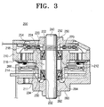
- a pre-load is applied, in the direction of an arrow, on the upper and the lower bearings 220 and 230 as shown in Figure 3.
- the principle by which such a pre-load is applied, will be described in detail with reference to Figure 4.
- the elastic member 270 applies a load on the inner ring 222 of the upper bearing 220.
- the inner ring 222 of the upper bearing 220 (which is joined to the shaft 240 in a loosely fitting manner) is displaced downwardly.
- the displacement of the inner ring 222 is shown in an exaggerated manner for an understanding of this embodiment of the present invention, a small movement in the displacement will in reality be made, This may not be identifiable by the human eye.
- an upper bearing ball is displaced downwardly.
- the outer ring 224 is forcedly fit to the rotational drum 210, the outer ring 224 is not moved.
- the structure of the upper bearing 220 enters a state as shown in Figure 4. Due to this structure, the force applied to the inner ring 222 of the upper bearing 220 by the elastic member 270 is transferred to the upper bearing ball 226 in the direction shown in Figure 4. Thus, the pre-load is applied.
- the force applied to the upper bearing ball 226 is transferred to the outer ring 224.
- the outer ring 224 of the upper bearing 220 is forcedly fit in the rotational drum 210, downward force is applied on the rotational drum 210.
- the force transferred to the rotational drum 210 is transferred to the outer ring 234 of the lower bearing 230 which forcedly fit in the middle axial cavity 211 of the rotational drum 210. Due to this force, the outer ring 234 of the lower bearing 230 is displaced downwardly. Due to such a displacement, the lower bearing ball 236 is moved slightly downwardly.
- the lower bearing 230 has an arrangement as shown in Figure 4.
- the force transferred to the outer ring 234 of the lower bearing 230 applies a pre-load, in the direction of the arrow as shown in Figure 4, on the lower bearing ball 236.
- an inner diameter of the inner ring 222 of the upper bearing 220 and an inner diameter of the inner ring 232 of the lower bearing 230 can be manufactured to be the same size, and accordingly, the upper bearing 220 and the lower bearing 230 can be constructed as the same bearing. Therefore, the upper and the lower bearings 220 and 230 need not be assembled separately. This simplifies the assembly process and reduces costs as the same bearing is used.
- the shaft 240 is forcedly fit in the lower axial cavity 262 formed on the fixing drum 260.
- the shaft 240 is fixed in the fixing drum 260 and the first assembly 300 is completed.
- the upper bearing 220 is forcedly fit, in the upward to downward direction, in the middle axial cavity 211, and the lower bearing 230 is forcedly fit, in the downward to upward direction of the rotational drum 210.
- the upper and the lower bearings 220 and 230 are forcedly pressed up until the bearing settling part 212, where they are located. This completes the second assembly 310.
- the shaft 240 forcedly fit in the lower axial cavity 262 of the fixing drum 260 in the first assembly 300 is inserted, in a sliding manner, through the inner rings 222 and 232 of the upper and the lower bearings 220 and 230 of the second assembly 310.
- the inner diameters of the inner rings 222 and 232 of the upper and the lower bearings 220 and 230 are larger than the diameter of the shaft 240, so that the shaft 240 is inserted, in a loosely fitting manner, into the inner rings 222 and 232 of the upper and the lower bearings 220 and 230.
- the elastic member 270 (in this case the coil spring) is inserted into the third assembly 320.
- the coil spring 270 is inserted around the outer periphery of the shaft 240. This completes the fourth assembly 330. It is preferable that as the coil spring 270 has a slightly larger diameter than the diameter of the shaft 240, the coil spring 270 is inserted by a little force from above. Due to the diameter, the coil spring 270 moves little around the outer periphery of the shaft 240 after being inserted onto the shaft 240.
- an upper part of the shaft 240 of the fourth assembly 330 is forcedly fit in the upper axial cavity 252 formed on the drum cover 250.
- the elastic member 270 is compressed by being pressed by one end of the drum cover 250.
- the compressed elastic member 270 applies a load to the inner ring 222 of the upper bearing 220, and the projection 264 of the fixing drum 260 applies a load on the inner ring 232 of the lower bearing 230.
- a pre-load is applied to the upper and the lower bearings 220 and 230 so that the rotational drum 210 is rotated in a stable manner.
- the inner diameters of the upper and the lower bearings are made the same, so that the assembling process is simplified. Also, since the same bearing is used for the upper and the lower bearings, bearing manufacturing costs can be reduced.
- the productivity of the head drum assembly can be improved.
Landscapes
- Support Of The Bearing (AREA)
Abstract
A head drum assembly and method of manufacturing a magnetic recording/reproducing apparatus are disclosed. In the assembly, for application of a pre-load on the upper and the lower bearings, the upper and the lower bearings are installed in a loosely fitting manner on the shaft. An elastic member for applying a load on an inner ring of either of the upper and the lower bearings is provided so that simplification of the manufacturing process of the head drum assembly, cost reduction, and productivity improvement are achieved.
Description
- The present invention relates to a head drum comprising a shaft, a head-carrying part rotatably mounted to the shaft by first and second axially spaced bearings, having inner and outer races, and a spring means for applying a bearing preloading force.
- Typically, a bearing is installed between a rotating body and a shaft which supports the rotating body as it rotates around the shaft. However, due to tolerances in the bearing, the accuracy of the rotation of the rotary body deteriorates. Thus, a head drum assembly of the magnetic recording/reproducing apparatus which is required to rotate accurately and at high speed compensates for the inaccuracies by applying a predetermined pre-load force on the bearing.
- Figure 1 is a cross-sectional view schematically showing a known head drum assembly.
- Referring to Figure 1, the head drum assembly of the magnetic recording/reproducing apparatus includes a
rotational drum 40 for supporting amagnetic head 44. Themagnetic head 44 records and reproduces (plays back) information by scanning a moving magnetic tape. Afixing drum 48 is forcedly fit, over therotational drum 40, onto a lower side of ashaft 10 which is joined to a middleaxial cavity 42 formed in therotational drum 40. An upper bearing 20 and alower bearing 30 configured so that they are located one above the other between therotational drum 40 and theshaft 10 and acoil spring 50 interposed between the upper bearing 20 and thelower bearing 30 is provided. Thecoil spring 50 applies a pre-load to the upper bearing 20 and thelower bearing 30 and is installed over theshaft 10 so as to apply the load on a respective inner ring (race) 22 and 32 in opposite directions. - Here, an
outer ring 24 of the upper bearing 20 is forcedly fitted adjacent the middleaxial cavity 42, and theinner ring 22 of the upper bearing 20 is forcedly fit to theshaft 10. Anouter ring 34 of thelower bearing 30 is forcedly fit adjacent the middleaxial cavity 42 and theinner ring 32 of thelower bearing 30 is inserted onto theshaft 10 in a loosely fitting manner. Thecoil spring 50 applies a load, in opposing directions, to theinner ring 22 of the upper bearing 20 and theinner ring 32 of thelower bearing 30. Since theinner ring 22 of the upper bearing 20 is forcedly fit onto theshaft 10, force applied to theinner ring 22 of the upper bearing 20 by thecoil spring 50 is transferred to the shaft and expended. However, since theinner ring 32 of thelower bearing 30 is loosely fit to theshaft 10, force transferred to theinner ring 32 of thelower bearing 30 by thecoil spring 50 causes displacement of theinner ring 32 of thelower bearing 30 onto the lower part of therotational drum 40. Accordingly, the force transferred to theinner ring 32 of thelower bearing 30, as shown in Figure 1, applies a load to a lower ball bearing 36. Also, the force transferred to the lower ball bearing 36 acts on a lower part of therotational drum 40 via theinner ring 32. This force is transferred to theouter ring 24 of the upper bearing 20 which is forcedly fit adjacent the middleaxial cavity 42 of therotational drum 40. This causes downwards displacement of theouter ring 24. The force transferred to theouter ring 24 of the upper bearing 20 acts on anupper bearing ball 26 in the direction shown in Figure 1 to apply a load thereon. - If the upper and the
lower bearings shaft 10, the force from thecoil spring 50 is transferred to theshaft 10 and expended. Therefore, the load is not applied on the upper and thelower bearing balls 26 and 36. Also, if both the upper and thelower bearings shaft 10 in a loosely fitting manner, theinner ring lower bearings rotational drum 40 moves up and down, which is problematic. Thus, theinner ring 22 of the upper bearing 20 is forcedly fit to theshaft 10 and theinner ring 32 of the lower bearing 30 is loosely fit to theshaft 10. - However, to form such a pre-loading structure because of the dimensional problem of the inner ring where the
inner ring 22 of the upper bearing 20 is forcedly fit to theshaft 10 and theinner ring 32 of thelower bearing 30 is loosely fitted to theshaft 10, the inner diameter of theinner ring 22 of theupper bearing 20 is not the same as the inner diameter of theinner ring 32 of thelower bearing 30. This means two types of bearings are used. Since two types of bearings are used, the assembly process becomes complicated, and the manufacturing costs of the bearings also increases. - The order in which the head drum is assembled will be described. The upper bearing 20 is forcedly fit to the
shaft 10. Next, the upper bearing 20 forcedly fit to theshaft 10 is forcedly fit in therotational drum 40. Thecoil spring 50 then fits over theshaft 10 from its lower part to its upper part so that thecoil spring 50 is positioned on theinner ring 22 of the upper bearing 20. Next, thelower bearing 30 is fitted to theshaft 10 and forcedly fit in therotational drum 40. Lastly, theshaft 10 inserted into therotational drum 40 which is forcedly fit in adrum cover 46 and thefixing drum 48. Since the foregoing process includes lots of forcedly fitting steps, manufacturing efficiency of the head drum assembly is reduced. - The present invention has been developed in order to solve the above drawbacks and other problems associated with the known art.
- The present invention relates to a head drum comprising a shaft, a head-carrying part rotatably mounted to the shaft by first and second axially spaced bearings, having inner and outer races, and a spring means for applying a bearing preloading force.
- A head drum according to the present invention is characterised in that the inner races are movable with respect to the shaft, a stop is provided on the shaft to limit the movement of the inner race of the second bearing in one direction and the spring means is installed such that the bearings are between the spring means and the stop and the preloading force is applied to the inner race of the first bearing in said direction.
- Other additional and/or preferred features are set forth in claims 12 and 13 appended hereto.
- An embodiment of the present invention will now be described, by way of example only, and with reference to Figures 2 to 5B of the accompanying drawings, in which:
- Figure 1 is a cross-sectional view of a known head drum assembly;
- Figure 2 is a perspective view schematically showing a magnetic
- recording/reproducing apparatus according to an embodiment of the present invention;
- Figure 3 is a cross-sectional view taken along line III-III of Figure 2;
- Figure 4 is a conceptual view illustrating a pre-load principle of upper and lower bearings shown in Figure 3; and
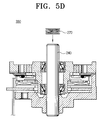
- Figures 5A through 5E are cross-sectional views illustrating a process for assembling a head drum assembly according to an embodiment of the present invention.
- In the drawings, it should be understood that like reference numerals refer to like structure and features.
- The matters defined in the description such as a detailed construction and elements are exemplary. Thus, it should be apparent that the present invention can be performed without the examples. Also, well-known functions or constructions are not described in detail since they would obscure the invention in unnecessary detail.
- Referring to Figure 2, the magnetic recording/reproducing apparatus according to an embodiment of the present invention includes a
deck 100 on which a magnetic tape is mounted and where a variety of parts for recording on and reproducing from the magnetic tape is installed. Thedeck 100 has asub-deck 120 and a main deck 110. Also provided is ahead drum assembly 200 which is installed on thedeck 100, for recording and information on and reading from the magnetic tape. Thehead drum assembly 200 is installed at a predetermined inclination on the main deck 110 and has arotational drum 210 rotating at a high speed, for recording and reproducing the information. Therotational drum 210 applies a predetermined pre-load, due to its high rotational speed, on a bearing. The bearing is located where therotational drum 210 is rotatably supported by ashaft 240. Such a pre-load structure and thehead drum assembly 200 will be described in detail in the following. - Referring to Figure 3, the
head drum assembly 200 includes arotational drum 210 whose central axis is arranged in parallel with ashaft 240. Upper andlower bearings shaft 240 between therotational drum 210 and theshaft 240. Adrum cover 250 and afixing drum 260 are arranged above and below therotational drum 210, respectively, and are fixed to both ends of theshaft 240. Anelastic member 270 is installed in such a way that one end presses against aninner ring 222 of the upper bearing 220 and its other end is supported by thedrum cover 250. - The
rotational drum 210 is coupled to theshaft 240 having therotational drum 210 interposed between the upper and thelower bearings shaft 240. Rotation is performed by interaction between amotor stator 214 installed on thefixing drum 260 and therotor 266 installed in the lower part of therotational drum 210. If therotational drum 210 rotates, ahead 216 fixed on therotational drum 210 obtains and reads information or, records information onto the magnetic tape. - The
outer rings lower bearings axial cavity 211 formed in therotational drum 210, so that thesebearings rotational drum 210. Also, the upper and thelower bearings shaft 240 in a loosely fitting manner. The upper end of theinner ring 222 is pressed against by theelastic member 270 and the lower end of theouter ring 224 is settled on abearing settling part 212 formed on the middleaxial cavity 211 of therotational drum 210. The lower end of theinner ring 232 of the lower bearing is supported by aprojection 264 formed on the upper end of a loweraxial cavity 262 of the fixingdrum 260. Also, the upper end of theouter ring 234 is settled on abearing settling part 212 formed on the middleaxial cavity 211 of therotational drum 210. - An upper
axial cavity 252 is formed on thedrum cover 250 so that the upper part of theshaft 240 is fixed in a forcedly fitting manner. Theelastic member 270 is supported by the periphery of the lower part of the upperaxial cavity 252. Also, a fixedtransformer 254 is installed on thedrum cover 250 which corresponds to arotational transformer 218 installed on therotational drum 210. With such a construction, signals can be exchanged between therotational drum 210 and the controlling part. Since a detailed description would be known to those skilled in the art, a detailed description will be omitted. - A lower
axial cavity 262 is formed on the fixingdrum 260 so that the fixingdrum 260 is forcedly fixed to the lower part of theshaft 240. Aupward projection 264 is formed on the periphery of the upper edge of the loweraxial cavity 262, and the lower end of theinner ring 232 is supported by thisprojection 264. Also, amotor stator 214 is installed on the fixingdrum 260 so that it corresponds to arotor 266 fixed on therotational drum 210. - The
elastic member 270 is supported on one end by the upper end of theinner ring 222 so that it applies a load to theinner ring 222 of theupper bearing 220. The other end of theelastic member 270 is supported by the periphery of the lower part of the upperaxial cavity 252 of thedrum cover 250. - Although the fixing
transformer 254 is fixed to thedrum cover 250 and themotor stator 214 is installed on the fixingdrum 260 in this embodiment, the present invention is not limited to this construction. Namely, thehead drum assembly 200 may be changed so that themotor stator 214 is installed in thedrum cover 250 and the fixingtransformer 254 is installed on the fixingdrum 260. Also, a coil spring is shown in the drawing as an example of theelastic member 270, the elastic member is not limited to this and the embodiment of the present invention is applicable to any member as far as it has elasticity. - A pre-load is applied, in the direction of an arrow, on the upper and the
lower bearings - Referring to Figure 4, the
elastic member 270 applies a load on theinner ring 222 of theupper bearing 220. By applying such a load, theinner ring 222 of the upper bearing 220 (which is joined to theshaft 240 in a loosely fitting manner) is displaced downwardly. Though the displacement of theinner ring 222 is shown in an exaggerated manner for an understanding of this embodiment of the present invention, a small movement in the displacement will in reality be made, This may not be identifiable by the human eye. As theinner ring 222 is displaced downwardly, an upper bearing ball is displaced downwardly. However, as the outer ring 224is forcedly fit to therotational drum 210, theouter ring 224 is not moved. Resultantly, the structure of theupper bearing 220 enters a state as shown in Figure 4. Due to this structure, the force applied to theinner ring 222 of theupper bearing 220 by theelastic member 270 is transferred to theupper bearing ball 226 in the direction shown in Figure 4. Thus, the pre-load is applied. - The force applied to the
upper bearing ball 226 is transferred to theouter ring 224. At this point, since theouter ring 224 of theupper bearing 220 is forcedly fit in therotational drum 210, downward force is applied on therotational drum 210. The force transferred to therotational drum 210 is transferred to theouter ring 234 of thelower bearing 230 which forcedly fit in the middleaxial cavity 211 of therotational drum 210. Due to this force, theouter ring 234 of thelower bearing 230 is displaced downwardly. Due to such a displacement, thelower bearing ball 236 is moved slightly downwardly. Thus, thelower bearing 230 has an arrangement as shown in Figure 4. Due to such an arrangement, the force transferred to theouter ring 234 of thelower bearing 230 applies a pre-load, in the direction of the arrow as shown in Figure 4, on thelower bearing ball 236. According to the above pre-load structure, an inner diameter of theinner ring 222 of theupper bearing 220 and an inner diameter of theinner ring 232 of thelower bearing 230 can be manufactured to be the same size, and accordingly, theupper bearing 220 and thelower bearing 230 can be constructed as the same bearing. Therefore, the upper and thelower bearings - Referring to Figure 5A, the
shaft 240 is forcedly fit in the loweraxial cavity 262 formed on the fixingdrum 260. By such forcedly fitting, theshaft 240 is fixed in the fixingdrum 260 and thefirst assembly 300 is completed. - Referring to Figure 5B, the
upper bearing 220 is forcedly fit, in the upward to downward direction, in the middleaxial cavity 211, and thelower bearing 230 is forcedly fit, in the downward to upward direction of therotational drum 210. The upper and thelower bearings bearing settling part 212, where they are located. This completes thesecond assembly 310. - Referring to Figure 5C, the
shaft 240 forcedly fit in the loweraxial cavity 262 of the fixingdrum 260 in thefirst assembly 300, is inserted, in a sliding manner, through theinner rings lower bearings second assembly 310. This completes thethird assembly 320. The inner diameters of theinner rings lower bearings shaft 240, so that theshaft 240 is inserted, in a loosely fitting manner, into theinner rings lower bearings projection 264 projected upward from the outer periphery of the loweraxial cavity 262 of the fixingdrum 260 is touched by the inner diameter of thelower bearing 230. - Referring to Figure 5D, the elastic member 270 (in this case the coil spring) is inserted into the
third assembly 320. Thecoil spring 270, is inserted around the outer periphery of theshaft 240. This completes thefourth assembly 330. It is preferable that as thecoil spring 270 has a slightly larger diameter than the diameter of theshaft 240, thecoil spring 270 is inserted by a little force from above. Due to the diameter, thecoil spring 270 moves little around the outer periphery of theshaft 240 after being inserted onto theshaft 240. - Referring to Figure 5E, an upper part of the
shaft 240 of thefourth assembly 330 is forcedly fit in the upperaxial cavity 252 formed on thedrum cover 250. At this point, theelastic member 270 is compressed by being pressed by one end of thedrum cover 250. The compressedelastic member 270, applies a load to theinner ring 222 of theupper bearing 220, and theprojection 264 of the fixingdrum 260 applies a load on theinner ring 232 of thelower bearing 230. Thus, a pre-load is applied to the upper and thelower bearings rotational drum 210 is rotated in a stable manner. - As described above, according to the improved head drum assembly of the present invention and the magnetic recording/reproducing apparatus having the same, and the method for assembling the head drum assembly, the inner diameters of the upper and the lower bearings are made the same, so that the assembling process is simplified. Also, since the same bearing is used for the upper and the lower bearings, bearing manufacturing costs can be reduced.
- Also, since the number of forcedly fitting processes is reduced compared with the known assembling process for the head drum assembly, the productivity of the head drum assembly can be improved.
Claims (13)
- A head drum assembly of a magnetic recording/reproducing apparatus comprising:a rotational drum rotatably disposed on a shaft;an upper bearing and a lower bearing installed between the rotational drum and the shaft;a fixing drum and a drum cover respectively fixed to the shaft, the upper and the lower bearings being installed on the shaft in a loosely fitting manner to apply a pre-load on the upper and the lower bearings; andan elastic member for applying a load on an inner ring of either of the upper and the lower bearings.
- The head drum assembly according to claim 1, wherein the upper and the lower bearings have the same diameter.
- The head drum assembly according to claim 2, wherein a projection is formed on the fixing drum, for supporting the inner ring of the lower bearing, and the elastic member applies a load on the inner ring of the upper bearing.
- The head drum assembly according to claim 3, wherein the elastic member is a coil spring.
- A magnetic recording/reproducing apparatus comprising:a deck on which a variety of parts for recording and reproducing data on and from the magnetic tape is installed; anda head drum assembly which includes a rotational drum mounted on the deck and rotatably disposed on a shaft, for recording and reproducing information on and from the magnetic tape;an upper bearing and a lower bearing installed between the rotational drum and the shaft;a fixing drum and a drum cover fixed to the shaft, the upper and the lower bearings being installed on the shaft, in a loosely fitting manner to apply a pre-load on the upper and the lower bearings; andan elastic member for applying a load on an inner ring of either of the upper and the lower bearings is provided.
- The magnetic recording/reproducing apparatus according to claim 5, wherein the upper and the lower bearings have the same diameter.
- The magnetic recording/reproducing apparatus according to claim 6, wherein a projection is formed on the fixing drum, for supporting the inner ring of the lower bearing, and the elastic member applies a load on the inner ring of the upper bearing.
- A method for assembling a head drum assembly of a magnetic recording/reproducing apparatus rotatably disposed on a deck, for recording and reproducing data on and from a magnetic tape, the method comprising the steps of:preparing a first assembly by forcedly fitting a shaft in a fixing drum;preparing a second assembly by forcedly fitting a plurality of bearings in a rotational drum;combining the first assembly and the second assembly by loosely fitting a plurality of bearings in the shaft; andinstalling an elastic member on the shaft so that a load is applied on an inner ring of any one of a plurality of bearings.
- The method according to claim 8, wherein the step of installing the elastic member comprises the steps of:mounting the elastic member on the shaft so that one side of the inner ring of any one of a plurality of bearings contacts one side of the elastic member; andforcedly fitting the drum cover in the shaft so that a load is applied on the other side of the elastic member.
- The method according to claim 8, wherein a plurality of bearings comprises an upper bearing and a lower bearing, the fixing drum has a projection in its upper end, and the step of combining the first assembly and the second assembly comprises the steps of:loosely fitting the shaft in the lower bearing;loosely fitting the shaft in the upper bearing; andclosely fitting the second assembly in the shaft so that the inner ring of the lower bearing is supported by the projection.
- A head drum (200) comprising a shaft (240), a head-carrying part (210) rotatably mounted to the shaft (240) by first and second axially spaced bearings (220, 230), having inner and outer races (222, 224, 232, 234), and a spring means (270) for applying a bearing preloading force, characterised in that the inner races (222, 232) are movable with respect to the shaft (240), a stop (264) is provided on the shaft (240) to limit the movement of the inner race (222, 232) of the second bearing (230) in one direction and the spring means (270) is installed such that the bearings (220, 230) are between the spring means (270) and the stop (264) and the preloading force is applied to the inner race (222, 232) of the first bearing (220) in said direction.
- A head drum (200) according to claim 1, wherein the first and second bearings (220, 230) are identical and contact respectively first and second parts of the shaft (240) having the same diameter.
- A head drum (200) according to either one of claims 1 or 2, wherein the stop (264) is formed on a fixing drum (260) mounted on the shaft (240).
Applications Claiming Priority (1)
| Application Number | Priority Date | Filing Date | Title |
|---|---|---|---|
| KR1020040048818A KR20060000017A (en) | 2004-06-28 | 2004-06-28 | Head drum assembly, magnetic recording / playback apparatus having same and assembly method of head drum assembly |
Publications (1)
| Publication Number | Publication Date |
|---|---|
| EP1612776A2 true EP1612776A2 (en) | 2006-01-04 |
Family
ID=35170197
Family Applications (1)
| Application Number | Title | Priority Date | Filing Date |
|---|---|---|---|
| EP05104765A Withdrawn EP1612776A2 (en) | 2004-06-28 | 2005-06-01 | A Head Drum |
Country Status (5)
| Country | Link |
|---|---|
| US (1) | US20050286174A1 (en) |
| EP (1) | EP1612776A2 (en) |
| JP (1) | JP2006012395A (en) |
| KR (1) | KR20060000017A (en) |
| CN (1) | CN100351904C (en) |
Families Citing this family (1)
| Publication number | Priority date | Publication date | Assignee | Title |
|---|---|---|---|---|
| KR20050051858A (en) * | 2003-11-28 | 2005-06-02 | 삼성전자주식회사 | Head drum assembly of a tape recorder and method for assembling the same |
Family Cites Families (12)
| Publication number | Priority date | Publication date | Assignee | Title |
|---|---|---|---|---|
| JPS5436709A (en) * | 1977-08-26 | 1979-03-17 | Sony Corp | Position control circuit for rotary magnetic head |
| JP2765910B2 (en) * | 1989-01-30 | 1998-06-18 | 株式会社日立製作所 | Rotating head device and magnetic recording / reproducing device using the same |
| KR0121258Y1 (en) * | 1995-05-18 | 1998-08-01 | 배순훈 | Device for fixing a rotary transformer of a head drum |
| KR100220829B1 (en) * | 1996-06-19 | 1999-09-15 | 전주범 | Head drum for digital Vials |
| JPH1049942A (en) * | 1996-07-31 | 1998-02-20 | Victor Co Of Japan Ltd | Magnetic recording and reproducing device |
| KR100205713B1 (en) * | 1996-09-30 | 1999-07-01 | 전주범 | The oil supply device of the head drum assembly |
| JP3569437B2 (en) * | 1998-03-19 | 2004-09-22 | アルプス電気株式会社 | Method of assembling rotary head device |
| US7009817B2 (en) * | 2001-08-06 | 2006-03-07 | Funai Electric Co., Inc. | Rotary magnetic head device and method of producing a rotary magnetic head device |
| CN1497538A (en) * | 2002-10-07 | 2004-05-19 | 三星电子株式会社 | Head Drum Parts for Tape Recorders |
| KR20050051858A (en) * | 2003-11-28 | 2005-06-02 | 삼성전자주식회사 | Head drum assembly of a tape recorder and method for assembling the same |
| JP2005222569A (en) * | 2004-02-03 | 2005-08-18 | Hitachi Ltd | Rotating magnetic head drum device and magnetic recording / reproducing device using the same |
| KR20060000015A (en) * | 2004-06-28 | 2006-01-06 | 삼성전자주식회사 | Assembly method of head drum assembly of magnetic recording / playback device |
-
2004
- 2004-06-28 KR KR1020040048818A patent/KR20060000017A/en not_active Withdrawn
-
2005
- 2005-02-28 US US11/066,381 patent/US20050286174A1/en not_active Abandoned
- 2005-05-23 JP JP2005149722A patent/JP2006012395A/en active Pending
- 2005-05-23 CN CNB2005100728166A patent/CN100351904C/en not_active Expired - Fee Related
- 2005-06-01 EP EP05104765A patent/EP1612776A2/en not_active Withdrawn
Also Published As
| Publication number | Publication date |
|---|---|
| CN100351904C (en) | 2007-11-28 |
| JP2006012395A (en) | 2006-01-12 |
| KR20060000017A (en) | 2006-01-06 |
| CN1716385A (en) | 2006-01-04 |
| US20050286174A1 (en) | 2005-12-29 |
Similar Documents
| Publication | Publication Date | Title |
|---|---|---|
| JP3536022B2 (en) | Pivot bearing device | |
| US5547291A (en) | Preloaded rolling bearing units | |
| KR100529437B1 (en) | Disk holding device | |
| US5863136A (en) | Method of reducing axial runout of a rolling bearing unit and a rolling bearing unit in which axial runout has been reduced | |
| JP3725903B2 (en) | Bearing assembly, spindle motor and actuator using the bearing assembly, and magnetic disk device | |
| US7428125B2 (en) | Rotating disk storage device and pivot bearing | |
| US6702465B2 (en) | Exclusion seal for fluid dynamic bearing motors | |
| EP1612776A2 (en) | A Head Drum | |
| US20020053845A1 (en) | Method for setting gaps in hydrodynamic bearings | |
| US20050081228A1 (en) | Aligning device for a disk recording medium, and information recording/reproducing apparatus mounted with the same | |
| JP3201100B2 (en) | Magneto-optical disk spindle motor | |
| US5231557A (en) | Magnetic disk apparatus having rotary type actuator and a height reducing return spring | |
| US5861687A (en) | Motor and recording and/or reproducing apparatus using the motor | |
| EP0859361B1 (en) | Hard disk drive device | |
| EP1079121A1 (en) | A pivot assembly | |
| US6912795B1 (en) | Conical hydrodynamic bearing gauging apparatus and method | |
| EP0859445A2 (en) | Motor | |
| JP2000356219A (en) | Preloaded bearing device | |
| US20020150019A1 (en) | Low-profile pivot assembly | |
| JP2001078384A (en) | Spindle motor | |
| EP0898268A2 (en) | Precision rotator | |
| JPH0696514A (en) | Spindle motor | |
| JPS6334138Y2 (en) | ||
| JP2000023413A (en) | Dc motor | |
| JP2000179561A (en) | Bearing structure |
Legal Events
| Date | Code | Title | Description |
|---|---|---|---|
| PUAI | Public reference made under article 153(3) epc to a published international application that has entered the european phase |
Free format text: ORIGINAL CODE: 0009012 |
|
| AK | Designated contracting states |
Kind code of ref document: A2 Designated state(s): AT BE BG CH CY CZ DE DK EE ES FI FR GB GR HU IE IS IT LI LT LU MC NL PL PT RO SE SI SK TR |
|
| AX | Request for extension of the european patent |
Extension state: AL BA HR LV MK YU |
|
| STAA | Information on the status of an ep patent application or granted ep patent |
Free format text: STATUS: THE APPLICATION HAS BEEN WITHDRAWN |
|
| 18W | Application withdrawn |
Effective date: 20071213 |