EP1612756A2 - Alarm call point - Google Patents
Alarm call point Download PDFInfo
- Publication number
- EP1612756A2 EP1612756A2 EP05105127A EP05105127A EP1612756A2 EP 1612756 A2 EP1612756 A2 EP 1612756A2 EP 05105127 A EP05105127 A EP 05105127A EP 05105127 A EP05105127 A EP 05105127A EP 1612756 A2 EP1612756 A2 EP 1612756A2
- Authority
- EP
- European Patent Office
- Prior art keywords
- call point
- frangible element
- magnet
- lever
- switch means
- Prior art date
- Legal status (The legal status is an assumption and is not a legal conclusion. Google has not performed a legal analysis and makes no representation as to the accuracy of the status listed.)
- Withdrawn
Links
Images

Classifications
-
- G—PHYSICS
- G08—SIGNALLING
- G08B—SIGNALLING SYSTEMS, e.g. PERSONAL CALLING SYSTEMS; ORDER TELEGRAPHS; ALARM SYSTEMS
- G08B25/00—Alarm systems in which the location of the alarm condition is signalled to a central station, e.g. fire or police telegraphic systems
- G08B25/12—Manually actuated calamity alarm transmitting arrangements emergency non-personal manually actuated alarm, activators, e.g. details of alarm push buttons mounted on an infrastructure
-
- H—ELECTRICITY
- H01—ELECTRIC ELEMENTS
- H01H—ELECTRIC SWITCHES; RELAYS; SELECTORS; EMERGENCY PROTECTIVE DEVICES
- H01H3/00—Mechanisms for operating contacts
- H01H3/02—Operating parts, i.e. for operating driving mechanism by a mechanical force external to the switch
-
- H—ELECTRICITY
- H01—ELECTRIC ELEMENTS
- H01H—ELECTRIC SWITCHES; RELAYS; SELECTORS; EMERGENCY PROTECTIVE DEVICES
- H01H36/00—Switches actuated by change of magnetic field or of electric field, e.g. by change of relative position of magnet and switch, by shielding
Definitions
- This invention relates to a call point.
- Call points are manually actuable devices which are intended to give notice of some potentially hazardous event such as a fire or gas build-up. They generally comprise a frangible element, such as a sheet of glass or plastics material, which is broken or moved to operate a switch.
- the switch is connected to a suitable control panel or monitoring circuitry arranged such that, when actuated, this is interpreted as an alarm condition which will in turn trigger an alarm event such as a visual and/or audible alarm, a release of doors or closure of valves, depending upon the particular circumstances.
- the call point itself may be situated in a potentially explosive atmosphere, in such circumstances that the actuation of the call point may itself cause a hazard by igniting the surrounding atmosphere, and thus cause an explosion, due to sparking during the switching action.
- the present invention addresses this problem by providing that the switch is located within an enclosure which is adapted to prevent sparks from within it from igniting the outside atmosphere.
- an enclosure will be referred to herein as a safe enclosure.
- Safe enclosures may take the form of a housing which is sealed from the surrounding atmosphere or, if not sealed, is provided with explosion-proof passages from interior to exterior.
- a call point comprising a housing, a frangible element mounted within said housing in a position suitable to be broken or displaced by a user, switch means mounted within a safe enclosure and switch operating means operable to operate said switch means upon breakage or displacement of the frangible element.
- the switch means is a magnetically-operated type, and the switch operating means comprises a magnet situated outside the safe enclosure and mounted so as to be movable into or out of the magnetic influence of the switch means upon breakage or displacement of the frangible element.
- the switch means may, for example, take the form of a reed switch.
- the magnet is mounted on a lever which is pivoted so as to move the magnet into or out of the influence of the switch means.
- the lever is arranged directly or indirectly to bear against the frangible element so that it rotates whenever the frangible element is broken or displaced.
- the lever may rest against the frangible element by gravity, or it may be biased against the frangible element by means of a spring.
- the magnet in its normal position, is positioned such as to maintain the switch means in an operated state so that the arrangement fails safe.
- two switch means are mounted within the safe enclosure, and are arranged such that the magnet moves from influencing one switch to influencing the other when the frangible element is broken or displaced.
- the call point comprises a housing 1 having a main body 2, front cover 3 and rear cover 4.
- the rear cover 4 is sealingly attached to the main body 2 by means of an o-ring seal 5, and this creates a sealed chamber 6 which defines a safe enclosure.
- Behind the front cover 2 is a space 7 which is isolated from the chamber 6 by the main body 2.
- the front cover 2 has a window 8 behind which is mounted a frangible element 9 in the form of a rectangular sheet of frangible material, typically glass.
- a lever/magnet assembly is mounted within the space 7 about a shaft 10 attached to the main body 2.
- the lever/magnet assembly comprises a cam 11 rotatably mounted on the shaft 10, to which is attached a lever 12.
- a magnet 13 is mounted towards the distal end of lever 12.
- a spring 14, shown diagrammatically for clarity, is attached between the lever 12 and a suitable point on the main body 2 so as to tend to bias the lever/magnet assembly in an anticlockwise direction.
- the cam 11 is positioned in such a way that the spring acts to bias the cam against an edge of the frangible element 9 so that, in the event of breakage or displacement of the frangible element, the edge falls away, causing the cam 11, and hence lever 12 to rotate anticlockwise about the shaft 10, as illustrated in Figure 4.
- a reed switch 15 which may optionally be mounted on a printed circuit board (PCB).
- the reed switch is mounted in a depression 16 formed in the rear surface of the main body 1 to create a wall 17 of reduced thickness between the space 7 and the chamber 6.
- the depression 16 may be filled with resin or other suitable material to encapsulate the switch 15.
- the reed switch 15 is positioned to lie directly opposite the magnet 13 when the lever/magnet assembly is in its normal position i.e. that shown in Figure 4. In this position, the influence of the magnet 13 is felt through the wall 17 and maintains the reed switch in the actuated position - which may be normally off or normally on, depending upon the configuration of the contacts.
- a second reed switch 18 may optionally be fitted in the depression 16, and positioned to lie opposite the magnet 13 when in the Figure 4 position.
- the call point may therefore, provide a "change-over" switch function rather than just a "normally open” or “normally closed” function which would be the case if only a single reed switch 15 is fitted.
- Figure 5 where A shows a changeover configuration from just a single reed switch 15. Reed switches with changeover contacts are available, but they tend to have a lower current rating than, say, a single normally-open reed switch.
- Figure 5 B and C show that use of two reed switches 15 and 18 enable changeover functionality, whilst using single pole switches having higher current ratings.
- a flag 19 may optionally be mounted at the distal end of the lever 12 to give a visible indication that the call point has been operated through a window 20 in the front cover 3.
- a magnet switch may be installed on the rear cover 4, associated with a further reed switch attached to the main body 2 (or vice versa). In the event that the main body 2 is removed from the rear cover, the further reed switch will be energised to activate some form of alarm or other indication.
- the reed switch 15 may be omitted, and a reed switch 18 only fitted, so that this is actuated when the magnet 13 moves to the Figure 4 position.
- the reed switch is unable to be energised in the normal position of the call point, which removes the "fail-safe" advantage mentioned above, and may also mean more incidences of "nuisance tripping" or "bounce", caused by local vibrations or shocks - a reed switch which is constantly actuated is less susceptible to such problems.
Landscapes
- Business, Economics & Management (AREA)
- Emergency Management (AREA)
- Physics & Mathematics (AREA)
- General Physics & Mathematics (AREA)
- Switches That Are Operated By Magnetic Or Electric Fields (AREA)
- Air Bags (AREA)
Abstract
Description
- This invention relates to a call point.
- Call points are manually actuable devices which are intended to give notice of some potentially hazardous event such as a fire or gas build-up. They generally comprise a frangible element, such as a sheet of glass or plastics material, which is broken or moved to operate a switch. The switch is connected to a suitable control panel or monitoring circuitry arranged such that, when actuated, this is interpreted as an alarm condition which will in turn trigger an alarm event such as a visual and/or audible alarm, a release of doors or closure of valves, depending upon the particular circumstances.
- Sometimes the call point itself may be situated in a potentially explosive atmosphere, in such circumstances that the actuation of the call point may itself cause a hazard by igniting the surrounding atmosphere, and thus cause an explosion, due to sparking during the switching action.
- The present invention addresses this problem by providing that the switch is located within an enclosure which is adapted to prevent sparks from within it from igniting the outside atmosphere. Such an enclosure will be referred to herein as a safe enclosure. Safe enclosures may take the form of a housing which is sealed from the surrounding atmosphere or, if not sealed, is provided with explosion-proof passages from interior to exterior.
- According to the invention there is provided a call point comprising a housing, a frangible element mounted within said housing in a position suitable to be broken or displaced by a user, switch means mounted within a safe enclosure and switch operating means operable to operate said switch means upon breakage or displacement of the frangible element.
- In an embodiment the switch means is a magnetically-operated type, and the switch operating means comprises a magnet situated outside the safe enclosure and mounted so as to be movable into or out of the magnetic influence of the switch means upon breakage or displacement of the frangible element. The switch means may, for example, take the form of a reed switch.
- In a preferred embodiment the magnet is mounted on a lever which is pivoted so as to move the magnet into or out of the influence of the switch means. The lever is arranged directly or indirectly to bear against the frangible element so that it rotates whenever the frangible element is broken or displaced. The lever may rest against the frangible element by gravity, or it may be biased against the frangible element by means of a spring.
- Preferably, in its normal position, the magnet is positioned such as to maintain the switch means in an operated state so that the arrangement fails safe.
- In an embodiment, two switch means are mounted within the safe enclosure, and are arranged such that the magnet moves from influencing one switch to influencing the other when the frangible element is broken or displaced.
- In order that the invention may be better understood, an embodiment thereof will now be described by way of example only, and with reference to the accompanying drawings in which:
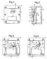
- Figure 1 is a front view of a call point constructed in accordance with the invention;
- Figure 2 is a sectional view of the call point of Figure 1;
- Figures 3 and 4 are front views of the call point of Figure 2, with the front cover removed to show the interior, and showing in the respective views two alternative operating positions; and
- Figure 5 are diagrams showing three alternative arrangements of the reed switch contacts.
- Referring to Figures 1 to 4, the call point comprises a housing 1 having a
main body 2,front cover 3 and rear cover 4. The rear cover 4 is sealingly attached to themain body 2 by means of an o-ring seal 5, and this creates a sealed chamber 6 which defines a safe enclosure. Behind thefront cover 2 is aspace 7 which is isolated from the chamber 6 by themain body 2. Thefront cover 2 has awindow 8 behind which is mounted afrangible element 9 in the form of a rectangular sheet of frangible material, typically glass. - A lever/magnet assembly is mounted within the
space 7 about ashaft 10 attached to themain body 2. The lever/magnet assembly comprises acam 11 rotatably mounted on theshaft 10, to which is attached alever 12. Amagnet 13 is mounted towards the distal end oflever 12. Aspring 14, shown diagrammatically for clarity, is attached between thelever 12 and a suitable point on themain body 2 so as to tend to bias the lever/magnet assembly in an anticlockwise direction. Thecam 11 is positioned in such a way that the spring acts to bias the cam against an edge of thefrangible element 9 so that, in the event of breakage or displacement of the frangible element, the edge falls away, causing thecam 11, and hence lever 12 to rotate anticlockwise about theshaft 10, as illustrated in Figure 4. - Situated within the chamber 6 is a
reed switch 15 which may optionally be mounted on a printed circuit board (PCB). The reed switch is mounted in adepression 16 formed in the rear surface of the main body 1 to create awall 17 of reduced thickness between thespace 7 and the chamber 6. Thedepression 16 may be filled with resin or other suitable material to encapsulate theswitch 15. As shown in Figure 3, thereed switch 15 is positioned to lie directly opposite themagnet 13 when the lever/magnet assembly is in its normal position i.e. that shown in Figure 4. In this position, the influence of themagnet 13 is felt through thewall 17 and maintains the reed switch in the actuated position - which may be normally off or normally on, depending upon the configuration of the contacts. - Upon breakage or displacement of the
frangible element 9, themagnet 13 moves, as described above, to the position shown in Figure 4, at which point thereed switch 15 is de-activated. - A
second reed switch 18 may optionally be fitted in thedepression 16, and positioned to lie opposite themagnet 13 when in the Figure 4 position. Thus it will be seen that breakage or displacement of thefrangible element 9 will, in this case, change the state of the contacts in bothreed switches single reed switch 15 is fitted. This is illustrated in Figure 5 where A shows a changeover configuration from just asingle reed switch 15. Reed switches with changeover contacts are available, but they tend to have a lower current rating than, say, a single normally-open reed switch. Figure 5 B and C show that use of tworeed switches - A
flag 19 may optionally be mounted at the distal end of thelever 12 to give a visible indication that the call point has been operated through awindow 20 in thefront cover 3. - In a further option (not shown) a magnet switch may be installed on the rear cover 4, associated with a further reed switch attached to the main body 2 (or vice versa). In the event that the
main body 2 is removed from the rear cover, the further reed switch will be energised to activate some form of alarm or other indication. - In a still further option the
reed switch 15 may be omitted, and areed switch 18 only fitted, so that this is actuated when themagnet 13 moves to the Figure 4 position. This means that the reed switch is unable to be energised in the normal position of the call point, which removes the "fail-safe" advantage mentioned above, and may also mean more incidences of "nuisance tripping" or "bounce", caused by local vibrations or shocks - a reed switch which is constantly actuated is less susceptible to such problems. - It will be seen that the call point described above can be safely operated by a user without the danger that the call point itself might cause an explosion or fire due to ignition of flammable gas or vapour due to sparking of the reed switch contacts. In addition, connections to external circuitry can be made within the chamber 6 so that any sparking due to poor contacts is likewise protected.
Claims (13)
- A call point comprising a housing, a frangible element mounted within said housing in a position suitable to be broken or displaced by a user, switch means mounted within a safe enclosure and switch operating means operable to operate said switch means upon breakage or displacement of the frangible element.
- A call point as claimed in claim 1 wherein the switch means is of the magnetically operated type, and the switch operating means comprises a magnet situated outside the safe enclosure and mounted so as to be moveable into or out of the influence of the switch means upon breakage or displacement of the frangible element.
- A call point as claimed in claim 1 wherein the switch means comprises one or more reed switches.
- A call point as claimed in either one of claims 2 or 3 wherein the magnet is mounted on a lever which is pivoted so as to move the magnet into or out of the influence of the or each switch means.
- A call point as claimed in claim 4 wherein the lever is arranged to directly or indirectly bear against the frangible element so that it rotates whenever the frangible element is broken or displaced.
- A call point as claimed in claim 5 wherein the lever is biased against the frangible element by the force of gravity.
- A call point as claimed in claim 5 wherein the lever is biased against the frangible element by means of a spring.
- A call point as claimed in any one of claims 4 to 7 wherein the lever is carried on a pivotally mounted cam, said cam being biased against an edge of the frangible element.
- A call point as claimed in any one of claims 4 to 8 wherein two switch means are provided, said switch means being spaced apart and positioned such that, in a first normal position of the lever, a first of said switch means comes under the influence of the magnet and, in a second position of the lever, after breakage or displacement of the frangible element, the second of said switch means comes under the influence of the magnet.
- A call point as claimed in claim 9 wherein each of said switch means comprises a single pole reed switch.
- A call point as claimed in any one claims 2 to 10 further including flag means which is moveable into a position in which it visually indicates that the call point has been operated, said flag means being mechanically connected to said magnet so as to move with said magnet upon breakage or displacement of the frangible element.
- A call point as claimed in claim 11 wherein said flag means becomes visible, upon operation of the call point, in a window in the housing.
- A call point as claimed in any one of the preceding claims wherein said safe enclosure takes the form of a sealed chamber within said housing.
Applications Claiming Priority (1)
| Application Number | Priority Date | Filing Date | Title |
|---|---|---|---|
| GB0414782A GB2415830B (en) | 2004-07-01 | 2004-07-01 | Call point |
Publications (2)
| Publication Number | Publication Date |
|---|---|
| EP1612756A2 true EP1612756A2 (en) | 2006-01-04 |
| EP1612756A3 EP1612756A3 (en) | 2006-12-27 |
Family
ID=32843412
Family Applications (1)
| Application Number | Title | Priority Date | Filing Date |
|---|---|---|---|
| EP05105127A Withdrawn EP1612756A3 (en) | 2004-07-01 | 2005-06-10 | Alarm call point |
Country Status (2)
| Country | Link |
|---|---|
| EP (1) | EP1612756A3 (en) |
| GB (1) | GB2415830B (en) |
Cited By (2)
| Publication number | Priority date | Publication date | Assignee | Title |
|---|---|---|---|---|
| EP1988526A2 (en) | 2007-04-30 | 2008-11-05 | Robert Bosch Gmbh | Notification device with manual disengagement |
| CN102867668A (en) * | 2012-09-12 | 2013-01-09 | 广东电网公司江门供电局 | Lock cylinder software type anti-misoperation mechanism for five-prevention 10kV switching cabinet |
Citations (1)
| Publication number | Priority date | Publication date | Assignee | Title |
|---|---|---|---|---|
| US4359719A (en) | 1980-10-06 | 1982-11-16 | Honeywell Inc. | Hall effect alarm pull station |
Family Cites Families (5)
| Publication number | Priority date | Publication date | Assignee | Title |
|---|---|---|---|---|
| US4857679A (en) * | 1986-11-20 | 1989-08-15 | Bennett Brian S | Alarm system |
| GB9017708D0 (en) * | 1990-08-13 | 1990-09-26 | Amlani Manher | Signalling device |
| ATE162651T1 (en) * | 1992-10-13 | 1998-02-15 | Siemens Ag | HAND HAZARD DETECTOR |
| GB2370670B (en) * | 2000-09-22 | 2005-03-02 | Manhar Amlani | Emergency signalling device |
| GB2401992B (en) * | 2003-05-17 | 2006-12-13 | Kac Alarm Company Ltd | Call points |
-
2004
- 2004-07-01 GB GB0414782A patent/GB2415830B/en not_active Expired - Fee Related
-
2005
- 2005-06-10 EP EP05105127A patent/EP1612756A3/en not_active Withdrawn
Patent Citations (1)
| Publication number | Priority date | Publication date | Assignee | Title |
|---|---|---|---|---|
| US4359719A (en) | 1980-10-06 | 1982-11-16 | Honeywell Inc. | Hall effect alarm pull station |
Cited By (4)
| Publication number | Priority date | Publication date | Assignee | Title |
|---|---|---|---|---|
| EP1988526A2 (en) | 2007-04-30 | 2008-11-05 | Robert Bosch Gmbh | Notification device with manual disengagement |
| EP1988526A3 (en) * | 2007-04-30 | 2009-09-09 | Robert Bosch Gmbh | Notification device with manual disengagement |
| CN102867668A (en) * | 2012-09-12 | 2013-01-09 | 广东电网公司江门供电局 | Lock cylinder software type anti-misoperation mechanism for five-prevention 10kV switching cabinet |
| CN102867668B (en) * | 2012-09-12 | 2014-08-06 | 广东电网公司江门供电局 | Lock cylinder software type anti-misoperation mechanism for five-prevention 10kV switching cabinet |
Also Published As
| Publication number | Publication date |
|---|---|
| GB2415830B (en) | 2006-05-17 |
| GB0414782D0 (en) | 2004-08-04 |
| EP1612756A3 (en) | 2006-12-27 |
| GB2415830A (en) | 2006-01-04 |
Similar Documents
| Publication | Publication Date | Title |
|---|---|---|
| CN112582216B (en) | Contact suspension trigger mechanism for use with a switch device incorporating an explosive feature | |
| JP7405534B2 (en) | Passive trigger mechanism for use with switching devices incorporating pyrotechnic features | |
| KR100876408B1 (en) | Air circuit breaker with mechanical trip indicator | |
| EP0597570B1 (en) | Magnetic actuators | |
| US2924682A (en) | Magnetically actuated switches | |
| USRE39731E1 (en) | Alarm switch | |
| RU2701865C2 (en) | Switching device for bodies equipped with protection against external influences | |
| US3786380A (en) | Multi-pole circuit breaker | |
| US20080258911A1 (en) | Exit alarm escutcheon | |
| KR970018907A (en) | Control and signaling devices for protective switching devices | |
| CN106486899A (en) | For having the switchgear of the housing of environmental conservation | |
| CN107787518B (en) | Mechanical fuse device | |
| US4394934A (en) | Fluid dispensing anti-burglar device | |
| CA2411644A1 (en) | Internal fault indicator for power electrical devices | |
| GB2415830A (en) | Call point | |
| JP4108885B2 (en) | Operation box and its cover device | |
| CN101226860B (en) | Electric leakage breaker | |
| WO2020253272A1 (en) | Miniature circuit breaker | |
| JP3909277B2 (en) | Manual call device | |
| US5036303A (en) | Bell alarm accessory arrangement for molded case circuit interrupter | |
| US20040008517A1 (en) | Magnetically operated reed switch | |
| GB2177544A (en) | Electrical devices provided with circuit-breakers | |
| EP0834847A1 (en) | Electrical equipment for anti-theft installations or similar | |
| EP1521225A1 (en) | Alarm call point | |
| EP1724804B1 (en) | Reset module for an electrical safety device |
Legal Events
| Date | Code | Title | Description |
|---|---|---|---|
| PUAI | Public reference made under article 153(3) epc to a published international application that has entered the european phase |
Free format text: ORIGINAL CODE: 0009012 |
|
| AK | Designated contracting states |
Kind code of ref document: A2 Designated state(s): AT BE BG CH CY CZ DE DK EE ES FI FR GB GR HU IE IS IT LI LT LU MC NL PL PT RO SE SI SK TR |
|
| AX | Request for extension of the european patent |
Extension state: AL BA HR LV MK YU |
|
| PUAL | Search report despatched |
Free format text: ORIGINAL CODE: 0009013 |
|
| AK | Designated contracting states |
Kind code of ref document: A3 Designated state(s): AT BE BG CH CY CZ DE DK EE ES FI FR GB GR HU IE IS IT LI LT LU MC NL PL PT RO SE SI SK TR |
|
| AX | Request for extension of the european patent |
Extension state: AL BA HR LV MK YU |
|
| 17P | Request for examination filed |
Effective date: 20070620 |
|
| AKX | Designation fees paid |
Designated state(s): AT BE BG CH CY CZ DE DK EE ES FI FR GB GR HU IE IS IT LI LT LU MC NL PL PT RO SE SI SK TR |
|
| 17Q | First examination report despatched |
Effective date: 20071123 |
|
| GRAP | Despatch of communication of intention to grant a patent |
Free format text: ORIGINAL CODE: EPIDOSNIGR1 |
|
| STAA | Information on the status of an ep patent application or granted ep patent |
Free format text: STATUS: THE APPLICATION IS DEEMED TO BE WITHDRAWN |
|
| 18D | Application deemed to be withdrawn |
Effective date: 20090930 |