EP1612593A1 - Progressive refractive power lens and production method therefor - Google Patents
Progressive refractive power lens and production method therefor Download PDFInfo
- Publication number
- EP1612593A1 EP1612593A1 EP04724372A EP04724372A EP1612593A1 EP 1612593 A1 EP1612593 A1 EP 1612593A1 EP 04724372 A EP04724372 A EP 04724372A EP 04724372 A EP04724372 A EP 04724372A EP 1612593 A1 EP1612593 A1 EP 1612593A1
- Authority
- EP
- European Patent Office
- Prior art keywords
- distance
- eyeball
- reference point
- lens
- side refracting
- Prior art date
- Legal status (The legal status is an assumption and is not a legal conclusion. Google has not performed a legal analysis and makes no representation as to the accuracy of the status listed.)
- Granted
Links
Images




Classifications
-
- G—PHYSICS
- G02—OPTICS
- G02C—SPECTACLES; SUNGLASSES OR GOGGLES INSOFAR AS THEY HAVE THE SAME FEATURES AS SPECTACLES; CONTACT LENSES
- G02C7/00—Optical parts
- G02C7/02—Lenses; Lens systems ; Methods of designing lenses
- G02C7/06—Lenses; Lens systems ; Methods of designing lenses bifocal; multifocal ; progressive
- G02C7/061—Spectacle lenses with progressively varying focal power
- G02C7/068—Special properties achieved by the combination of the front and back surfaces
Definitions
- the present invention relates to a progressive power lens that is used as an eyesight-corrective spectacle lens for correcting presbyopia due to reduction of accommodation.
- the progressive power lens is provided with a distance portion having power to see far away, a near portion having power to see near objects, and located therebetween, an intermediate portion having power showing a progressive change.
- the power difference between the distance portion and the near portion is referred to as addition power, and is set to a value considered appropriate in consideration of a lens wearer's decreasing level of accommodation.
- the portions toward the lateral sides of both the intermediate portion and the near portion are referred to as aberration portion, not suitable for optical use. This is an inevitable drawback of a progressive power lens, needing to smoothly neutralize the power difference between the distance portion and the near portion.
- a spectacle lens is structured by an object-side refracting surface and an eyeball-side refracting surface.
- a progressive power lens is designated with, by lens manufacturers, a spot for measuring power for distance viewing and that for near viewing.
- those spots are explicitly printed on a lens refracting surface, for example. Even if not printed, a permanent mark provided to the lens may help to find such measurement spots by following the lens manufacturers' specifications.
- the spot for measuring power for distance viewing is referred to as distance reference point
- the spot for measuring power for near viewing is referred to as near reference point.
- the refracting surface i.e., so-called progressive surface
- the eyeball-side refracting surface is formed by a spherical surface or a toric surface that is directed to the direction of a cylinder axis in accordance with a lens wearers' prescribed dioptric power.
- a progressive power lens is referred to as external progressive power lens.
- a refracting surface is provided on the object side for causing a change of the image magnification. This results in larger image distortion.
- some people wearing a progressive power lens for the first time, and some people wearing a progressive power lens as a replacement with another of a different design may feel something is wrong.
- the object-side refracting surface is a spherical surface or an aspherical surface symmetrical to a rotation axis
- the eyeball-side refracting surface is a complex curved surface as a combination result of a progressive surface, a toric surface, and a corrective aspherical surface component for correction of lens off-axis aberration.
- a double-sided progressive power lens for sharing, for formation, between the object-side refracting surface and the eyeball-side refracting surface, an addition power component of a progressive surface.
- a progressive surface component causing the magnification change is partially observed on the object-side refracting surface.
- the distortion level can be better to a greater degree than with the external progressive power lens.
- a distance portion and a near portion are formed to be a piece.
- this inevitably defines the near portion by position.
- the fitting optimum for near viewing cannot be independently performed.
- an ophthalmoscopic lens is set ahead of a cornea by about 12 mm to select the dioptric power for the lens to derive any predetermined eyesight.
- an ophthalmoscopic lens is set ahead of the eye by about 12 mm similarly to the dioptric power for distance use to select the dioptric power.
- the dioptric power is determined under the condition that the optical axis of the ophthalmoscopic lens is in almost the same direction as the visual axis.
- the issue here is that, assuming if, for wearing, a progressive power lens made with the dioptric power for distance use and the dioptric power for near use determined as such, as shown in Fig.
- the optical axis of the lens when the optical axis of the lens is directed in the same direction as the visual axis in the distance portion, and when a lens is placed ahead of the eye by about 12 mm, the visual axis in the near portion is generally directed in a slanting direction, and the distance from the eye will be generally longer than 12 mm. Therefore, the dioptric power for near use actually working on the eye becomes different from the dioptric power of the lens.
- the optical axis in the distance portion may not be directed in the same direction as the visual axis, whereby the optical properties originally aimed by the lens designer cannot, problematically, be fully achieved.
- the progressive lens of such a recent type as described in the foregoing, where correction is applied in advance to the dioptric power in consideration of the dioptric power as worn position, even a slight difference in direction between the optical axis and the visual axis causes the optical properties to be considerably degraded.
- a progressive power lens of the present invention is directed to a progressive power lens structured by two refracting surfaces, an object-side refracting surface and an eyeball-side refracting surface.
- the progressive power lens is provided with a distance portion mainly for viewing objects in a distance range, a near portion mainly for viewing objects in a close range, and an intermediate portion mainly for viewing objects in an intermediate range in which a successive change is observed for power from the distance portion to the near portion.
- a distance reference point is set, and to the near portion, a near reference point is set.
- Such a progressive power lens is characterized in that, when the lens has presumably a reference spherical surface in its entirety that is defined by an average curvature of the eyeball-side refracting surface in the vicinity of the distance reference point, the eyeball-side refracting surface in the vicinity of the near reference point is located closer to the eyeball-side than the reference spherical surface in the vicinity of the near reference point.
- the present invention is also directed to a progressive power lens structured by two refracting surfaces, an object-side refracting surface and an eyeball-side refracting surface.
- the progressive power lens is also provided with a distance portion mainly for viewing objects in a distance range, a near portion mainly for viewing objects in a close range, and an intermediate portion mainly for viewing objects in an intermediate range in which a successive change is observed for power from the distance portion to the near portion.
- a distance reference point is set, and to the near portion, a near reference point is set.
- Such a progressive power lens is characterized in that a curvature along an intersection line defined by the eyeball-side refracting surface and a surface of section being perpendicular to the eyeball-side refracting surface and passing both the distance reference point and the near reference point shows an increase from the distance portion to the near portion in the portion entirely covering the distance reference point and the near reference point, or the portion partially covering the same.
- the present invention is also directed to a progressive power lens structured by two refracting surfaces, an object-side refracting surface and an eyeball-side refracting surface.
- the progressive power lens is provided with a distance portion mainly for viewing objects in a distance range, a near portion mainly for viewing objects in a close range, and an intermediate portion mainly for viewing objects in an intermediate range in which a successive change is observed for power from the distance portion to the near portion.
- a distance reference point is set, and to the near portion, a near reference point is set.
- Such a progressive power lens is characterized in that, when the lens has presumably a reference spherical surface in its entirety that is defined by an average curvature of the eyeball-side refracting surface in the vicinity of the distance reference point, the absolute value of a vertical component of a normal vector of the eyeball-side refracting surface at the near reference point is larger than the absolute value of a vertical component of a normal vector of the reference spherical surface at the near reference point.
- the eyeball-side refracting surfaces have the same shape even if the distance power and the addition power is different between right and left lenses.
- a progressive power lens whose eyeball-side refracting surface is a spherical surface, a toroidal surface, an aspherical surface symmetric to a rotation axis, or a progressive surface is manufactured through deformation of lens shape but not through change in thickness.
- a progressive power lens whose object-side refracting surface is a spherical surface, an aspherical surface symmetric to a rotation axis, or a progressive surface is manufactured through deformation of lens shape but not through change in thickness so that the progressive power lens described in any one of claims 1 to 4 is manufactured.
- the present invention relates to a method for manufacturing lenses for eyeglasses and, specifically, is applicable but not restrictive to a method for manufacturing progressive power lenses.
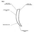
- Fig. 1 shows a cross-sectional view of a lens according to an embodiment of the present invention.
- a dotted line indicates a reference spherical surface derived by expanding, entirely over the lens, a spherical surface having an average curvature of an eyeball-side refracting surface in the vicinity of a distance reference point.
- the eyeball-side refracting surface of a progressive power lens of the present invention is characterized by being displaced in such a manner as to come closer to an eyeball than the reference spherical surface.
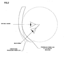
- a near portion comes closer to the eyeball side compared with a conventional progressive power lens. Thanks thereto, provided is better field of view for near viewing. Further, the normal of the eyeball-side refracting surface of the near portion is directed closer to the eyeball than with the conventional progressive power lens. Thus, the line of sight for near viewing is directed in an almost vertical direction due to the eyeball-side refracting surface, favorably preventing any possible influences such as aberration and others.
- the absolute value of a vertical component of a normal vector of the eyeball-side refracting surface at the near reference point is larger than the absolute value of a vertical component of a normal vector of the reference spherical surface at the near reference point.
- Fig. 3 shows a method for manufacturing the progressive power lens of the present invention with a simple procedure.
- the eyeball-side refracting surface and the object-side refracting surface both have complex free-form surfaces.
- using expensive cutting/polishing machines will allow to process those two surfaces with a predetermined prescription.
- the method of Fig. 3 is a manufacturing method at a lower cost.
- the lens of Fig. 3 is a progressive power lens of a conventional general type.
- the object-side refracting surface is a progressive surface in which a successive change is observed for surface power from the distance portion to the near portion, and the eyeball-side refracting surface is a spherical surface.
- the upper surface of a deforming metal mold is a deformed surface in the shape of the eyeball-side refracting surface of the progressive power lens of the present invention.
- the eyeball-side refracting surface When this deformed surface is placed relative to the eyeball-side refracting surface of the lens for heating, the eyeball-side refracting surface can be changed in shape along the displaced surface. If this is the case, the object-side refracting surface is also displaced by the same displacement amount as the eyeball-side refracting surface. Accordingly, this deforms the lens without changing the thickness at the respective points of the lens. In the resulting lens, irrespective of the different shape from the original shape, it is known that the part around the center of the lens can keep almost the same optical properties as the original lens.
- the progressive power lens of the present invention can be manufactured with the same method as an external progressive power lens whose object-side refracting surface is a progressive surface, and an internal progressive power lens whose eyeball-side refracting surface is a progressive surface.
- the distance from the eyeball to the near portion varies between right and left, causing the image magnification to be considerably different between right and left. As a result, this has been seriously affecting object viewing.
- the progressive power lens of the present invention without affecting the optical properties, the eyeball-side refracting surface can be in the same shape for both the right and left lenses. Accordingly, the distance from the eyeball to the near portion can be equalized between the right and left lenses, favorably providing glasses comfortable to wear.
- the near portion can be closer to the eyeball at the time of framing, and thus any problems such as image distortion and fluctuation unique to the progressive power lens can be reduced to a considerable degree.
- the eyeball-side refracting surface can be in the same shape without affecting the optical properties of the lens, and prevention measures can be successfully taken against any difference between right and left at the time of object viewing, and any difference at the time of object viewing due to the varying dioptric power.
- any type of the progressive power lens can be used as the progressive power lens of the present invention without impairing the optical properties only by changing, in shape, a progressive power lens whose eyeball-side refracting surface is a spherical surface, a toroidal surface, an aspherical surface symmetric to a rotation axis, or a progressive surface, or a progressive power lens whose object-side refracting surface is a spherical surface, an aspherical surface symmetrical to a rotation axis, or a progressive surface.
Landscapes
- Health & Medical Sciences (AREA)
- Ophthalmology & Optometry (AREA)
- Physics & Mathematics (AREA)
- General Health & Medical Sciences (AREA)
- General Physics & Mathematics (AREA)
- Optics & Photonics (AREA)
- Eyeglasses (AREA)
Abstract
Description
- The present invention relates to a progressive power lens that is used as an eyesight-corrective spectacle lens for correcting presbyopia due to reduction of accommodation.
- First of all, referring to Fig. 8, described is the basic structure of a progressive power lens. The progressive power lens is provided with a distance portion having power to see far away, a near portion having power to see near objects, and located therebetween, an intermediate portion having power showing a progressive change. The power difference between the distance portion and the near portion is referred to as addition power, and is set to a value considered appropriate in consideration of a lens wearer's decreasing level of accommodation. The portions toward the lateral sides of both the intermediate portion and the near portion are referred to as aberration portion, not suitable for optical use. This is an inevitable drawback of a progressive power lens, needing to smoothly neutralize the power difference between the distance portion and the near portion.
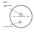
- Further, as shown in Fig. 9, a spectacle lens is structured by an object-side refracting surface and an eyeball-side refracting surface. Generally, a progressive power lens is designated with, by lens manufacturers, a spot for measuring power for distance viewing and that for near viewing. As shown in Fig. 10, generally, those spots are explicitly printed on a lens refracting surface, for example. Even if not printed, a permanent mark provided to the lens may help to find such measurement spots by following the lens manufacturers' specifications. The spot for measuring power for distance viewing is referred to as distance reference point, and the spot for measuring power for near viewing is referred to as near reference point.
- Here, the refracting surface, i.e., so-called progressive surface, generating addition power unique to progressive power lenses is often an object-side refracting surface as shown in Fig. 11. If this is the case, the eyeball-side refracting surface is formed by a spherical surface or a toric surface that is directed to the direction of a cylinder axis in accordance with a lens wearers' prescribed dioptric power. In this specification, such a progressive power lens is referred to as external progressive power lens. In the external progressive power lens, a refracting surface is provided on the object side for causing a change of the image magnification. This results in larger image distortion. Thus, some people wearing a progressive power lens for the first time, and some people wearing a progressive power lens as a replacement with another of a different design may feel something is wrong.
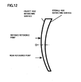
- To prevent distortion resulting from such image magnification change, recently commercialized has been an internal progressive power lens in which a progressive surface is placed on the eyeball side, details of which are found in WO97/19382 (Figs. 4, 10, and 15). In such an internal progressive power lens, as shown in Fig. 12, the object-side refracting surface is a spherical surface or an aspherical surface symmetrical to a rotation axis, and the eyeball-side refracting surface is a complex curved surface as a combination result of a progressive surface, a toric surface, and a corrective aspherical surface component for correction of lens off-axis aberration.
- Further, as described in WO97/19383 (Fig. 1), also commercialized has been a double-sided progressive power lens for sharing, for formation, between the object-side refracting surface and the eyeball-side refracting surface, an addition power component of a progressive surface. In such a double-sided addition lens, a progressive surface component causing the magnification change is partially observed on the object-side refracting surface. Thus, compared with the internal progressive power lens having the spherical object-side refracting surface, it is disadvantageous in terms of distortion. Surely, the distortion level can be better to a greater degree than with the external progressive power lens.
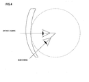
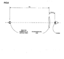
- In these progressive power lenses, a distance portion and a near portion are formed to be a piece. As a result, if mounting and fitting are done in such a manner as to provide the best optical properties for the distance portion, this inevitably defines the near portion by position. As a result, problematically, the fitting optimum for near viewing cannot be independently performed. For example, to determine the dioptric power for distance use, as shown in Fig. 6, an ophthalmoscopic lens is set ahead of a cornea by about 12 mm to select the dioptric power for the lens to derive any predetermined eyesight. To determine the dioptric power for near use, as shown in Fig. 7, although a viewing object is different in position, an ophthalmoscopic lens is set ahead of the eye by about 12 mm similarly to the dioptric power for distance use to select the dioptric power. In this manner, the dioptric power is determined under the condition that the optical axis of the ophthalmoscopic lens is in almost the same direction as the visual axis. The issue here is that, assuming if, for wearing, a progressive power lens made with the dioptric power for distance use and the dioptric power for near use determined as such, as shown in Fig. 4, when the optical axis of the lens is directed in the same direction as the visual axis in the distance portion, and when a lens is placed ahead of the eye by about 12 mm, the visual axis in the near portion is generally directed in a slanting direction, and the distance from the eye will be generally longer than 12 mm. Therefore, the dioptric power for near use actually working on the eye becomes different from the dioptric power of the lens.
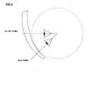
- In recent years, such a difference is set with consideration given in advance prior to correcting the dioptric power. Even if so, it is difficult to say that correction is applied sufficiently because the dioptric power requires widely varying corrections in consideration of the wearer's dioptric power, the direction of the cylinder axis, and others. Moreover, when the near portion has a distance from the eyeball, the image magnification of the lens is increased, thereby increasing the image size difference between the distance portion and the near portion. As a result, phenomena such as image distortion and fluctuation unique to progressive power lenses are enhanced, and sometimes resulting in customer complaints as not comfortable to wear. To avoid such complaints, at eyeglasses shops, the lens may be leaned forward to a greater angle as shown in Fig. 5 for lens framing in such a manner that the near portion comes closer to the eyeball. If this is the case, however, the optical axis in the distance portion may not be directed in the same direction as the visual axis, whereby the optical properties originally aimed by the lens designer cannot, problematically, be fully achieved. Especially with the progressive lens of such a recent type, as described in the foregoing, where correction is applied in advance to the dioptric power in consideration of the dioptric power as worn position, even a slight difference in direction between the optical axis and the visual axis causes the optical properties to be considerably degraded.
- To solve the above problems, there is to provide a lens of a design in which a near portion comes closer to an eyeball after a distance portion is fit ideally.
- For this purpose, a progressive power lens of the present invention is directed to a progressive power lens structured by two refracting surfaces, an object-side refracting surface and an eyeball-side refracting surface. The progressive power lens is provided with a distance portion mainly for viewing objects in a distance range, a near portion mainly for viewing objects in a close range, and an intermediate portion mainly for viewing objects in an intermediate range in which a successive change is observed for power from the distance portion to the near portion. To the distance range, a distance reference point is set, and to the near portion, a near reference point is set. Such a progressive power lens is characterized in that, when the lens has presumably a reference spherical surface in its entirety that is defined by an average curvature of the eyeball-side refracting surface in the vicinity of the distance reference point, the eyeball-side refracting surface in the vicinity of the near reference point is located closer to the eyeball-side than the reference spherical surface in the vicinity of the near reference point.
- Further, the present invention is also directed to a progressive power lens structured by two refracting surfaces, an object-side refracting surface and an eyeball-side refracting surface. The progressive power lens is also provided with a distance portion mainly for viewing objects in a distance range, a near portion mainly for viewing objects in a close range, and an intermediate portion mainly for viewing objects in an intermediate range in which a successive change is observed for power from the distance portion to the near portion. To the distance portion, a distance reference point is set, and to the near portion, a near reference point is set. Such a progressive power lens is characterized in that a curvature along an intersection line defined by the eyeball-side refracting surface and a surface of section being perpendicular to the eyeball-side refracting surface and passing both the distance reference point and the near reference point shows an increase from the distance portion to the near portion in the portion entirely covering the distance reference point and the near reference point, or the portion partially covering the same.
- The present invention is also directed to a progressive power lens structured by two refracting surfaces, an object-side refracting surface and an eyeball-side refracting surface. The progressive power lens is provided with a distance portion mainly for viewing objects in a distance range, a near portion mainly for viewing objects in a close range, and an intermediate portion mainly for viewing objects in an intermediate range in which a successive change is observed for power from the distance portion to the near portion. To the distance portion, a distance reference point is set, and to the near portion, a near reference point is set. Such a progressive power lens is characterized in that, when the lens has presumably a reference spherical surface in its entirety that is defined by an average curvature of the eyeball-side refracting surface in the vicinity of the distance reference point, the absolute value of a vertical component of a normal vector of the eyeball-side refracting surface at the near reference point is larger than the absolute value of a vertical component of a normal vector of the reference spherical surface at the near reference point.
- Further, characteristically, in a pair of right and left lenses, the eyeball-side refracting surfaces have the same shape even if the distance power and the addition power is different between right and left lenses.
- As a method for manufacturing such progressive power lenses of the present invention at a low cost, characteristically, a progressive power lens whose eyeball-side refracting surface is a spherical surface, a toroidal surface, an aspherical surface symmetric to a rotation axis, or a progressive surface is manufactured through deformation of lens shape but not through change in thickness.
- Further, characteristically, a progressive power lens whose object-side refracting surface is a spherical surface, an aspherical surface symmetric to a rotation axis, or a progressive surface is manufactured through deformation of lens shape but not through change in thickness so that the progressive power lens described in any one of
claims 1 to 4 is manufactured. - The present invention relates to a method for manufacturing lenses for eyeglasses and, specifically, is applicable but not restrictive to a method for manufacturing progressive power lenses.
-
- Fig. 1
- is a cross-sectional view of a progressive power lens of the present invention.
- Fig. 2
- is a conceptual diagram showing the effects of the progressive power lens of the present invention.
- Fig. 3
- is a conceptual diagram of a method for manufacturing the progressive power lens of the present invention.
- Fig. 4
- is a conceptual diagram of a conventional progressive power lens.
- Fig. 5
- is a conceptual diagram of the conventional progressive power lens.
- Fig. 6
- is a conceptual diagram of an examination of dioptric power for distance viewing.
- Fig. 7
- is a conceptual diagram of an examination of dioptric power for near viewing.
- Fig. 8
- is a conceptual diagram of a progressive power lens.
- Fig. 9
- is a cross-sectional view of a lens for eyeglasses.
- Fig. 10
- is a layout diagram of a progressive power lens.
- Fig. 11
- is a conceptual diagram of an external progressive power lens.
- Fig. 12
- is a conceptual diagram of an internal progressive power lens.
- Fig. 1 shows a cross-sectional view of a lens according to an embodiment of the present invention. In the drawing, a dotted line indicates a reference spherical surface derived by expanding, entirely over the lens, a spherical surface having an average curvature of an eyeball-side refracting surface in the vicinity of a distance reference point. The eyeball-side refracting surface of a progressive power lens of the present invention is characterized by being displaced in such a manner as to come closer to an eyeball than the reference spherical surface. With such a structure, when the lens is used for glasses as shown in Fig. 2, even if framing is so done as to direct the optical axis in a distance portion in almost the same direction as the line of sight, a near portion comes closer to the eyeball side compared with a conventional progressive power lens. Thanks thereto, provided is better field of view for near viewing. Further, the normal of the eyeball-side refracting surface of the near portion is directed closer to the eyeball than with the conventional progressive power lens. Thus, the line of sight for near viewing is directed in an almost vertical direction due to the eyeball-side refracting surface, favorably preventing any possible influences such as aberration and others. This means, with mathematical definition, the absolute value of a vertical component of a normal vector of the eyeball-side refracting surface at the near reference point is larger than the absolute value of a vertical component of a normal vector of the reference spherical surface at the near reference point.
- As will be understood from Fig. 1, to make the eyeball-side refracting surface come closer to the eyeball than the reference spherical surface in the progressive power lens of the present invention, the curvature along the eyeball-side refracting surface is set larger than the curvature of the reference spherical surface somewhere between the distance reference point and the near reference point. Fig. 3 shows a method for manufacturing the progressive power lens of the present invention with a simple procedure. In the progressive power lens of the present invention, the eyeball-side refracting surface and the object-side refracting surface both have complex free-form surfaces. Here, with the current technologies, using expensive cutting/polishing machines will allow to process those two surfaces with a predetermined prescription. If this is the case, however, the processing time takes longer and results in higher manufacturing cost. The method of Fig. 3 is a manufacturing method at a lower cost. The lens of Fig. 3 is a progressive power lens of a conventional general type. The object-side refracting surface is a progressive surface in which a successive change is observed for surface power from the distance portion to the near portion, and the eyeball-side refracting surface is a spherical surface. The upper surface of a deforming metal mold is a deformed surface in the shape of the eyeball-side refracting surface of the progressive power lens of the present invention. When this deformed surface is placed relative to the eyeball-side refracting surface of the lens for heating, the eyeball-side refracting surface can be changed in shape along the displaced surface. If this is the case, the object-side refracting surface is also displaced by the same displacement amount as the eyeball-side refracting surface. Accordingly, this deforms the lens without changing the thickness at the respective points of the lens. In the resulting lens, irrespective of the different shape from the original shape, it is known that the part around the center of the lens can keep almost the same optical properties as the original lens. In such a manner, the progressive power lens of the present invention can be manufactured with the same method as an external progressive power lens whose object-side refracting surface is a progressive surface, and an internal progressive power lens whose eyeball-side refracting surface is a progressive surface.
- Moreover, in a case where a pair of right and left glasses have each different prescribed dioptric power, with the conventional progressive power lens, the distance from the eyeball to the near portion varies between right and left, causing the image magnification to be considerably different between right and left. As a result, this has been seriously affecting object viewing. With the progressive power lens of the present invention, on the other hand, without affecting the optical properties, the eyeball-side refracting surface can be in the same shape for both the right and left lenses. Accordingly, the distance from the eyeball to the near portion can be equalized between the right and left lenses, favorably providing glasses comfortable to wear.
- With the progressive power lens of the present invention, compared with the conventional progressive power lens, the near portion can be closer to the eyeball at the time of framing, and thus any problems such as image distortion and fluctuation unique to the progressive power lens can be reduced to a considerable degree. Moreover, the eyeball-side refracting surface can be in the same shape without affecting the optical properties of the lens, and prevention measures can be successfully taken against any difference between right and left at the time of object viewing, and any difference at the time of object viewing due to the varying dioptric power.
- What is more, any type of the progressive power lens can be used as the progressive power lens of the present invention without impairing the optical properties only by changing, in shape, a progressive power lens whose eyeball-side refracting surface is a spherical surface, a toroidal surface, an aspherical surface symmetric to a rotation axis, or a progressive surface, or a progressive power lens whose object-side refracting surface is a spherical surface, an aspherical surface symmetrical to a rotation axis, or a progressive surface.
Claims (6)
- A progressive power lens that is structured by two refracting surfaces, an object-side refracting surface and an eyeball-side refracting surface, comprising: a distance portion mainly for viewing objects in a distance range; a near portion mainly for viewing objects in a close range; and an intermediate portion mainly for viewing objects in an intermediate range in which a successive change is observed for power from the distance portion to the near portion, and a distance reference point is set to the distance portion and a near reference point is set to the near portion,
characterized in that when the lens is presumed to have a reference spherical surface in its entirety that is defined by a curvature equal to the average curvature of the eyeball-side refracting surface of the lens in a vicinity of the distance reference point, the eyeball-side refracting surface in a vicinity of the near reference point is located closer to the eyeball side than the reference spherical surface in a vicinity of the near reference point. - A progressive power lens structured by two refracting surfaces, an object-side refracting surface and an eyeball-side refracting surface, comprising: a distance portion mainly for viewing objects in a distance range; a near portion mainly for viewing objects in a close range; and an intermediate portion mainly for viewing objects in an intermediate range in which a successive change is observed for power from the distance portion to the near portion, and a distance reference point is set to the distance portion and a near reference point is set to the near portion,
characterized in that a curvature along an intersection line defined by the eyeball-side refracting surface and a surface of section being perpendicular to the eyeball-side refracting surface and passing through both the distance reference point and the near reference point shows an increase from the distance portion to the near portion in a portion entirely covering the distance reference point and the near reference point, or a portion partially covering the same. - A progressive power lens structured by two refracting surfaces, an object-side refracting surface and an eyeball-side refracting surface, comprising: a distance portion mainly for viewing objects in a distance range; a near portion mainly for viewing objects in a close range; and an intermediate portion mainly for viewing objects in an intermediate range in which a successive change is observed for power from the distance portion to the near portion, and a distance reference point is set to the distance portion and a near reference point is set to the near portion,
characterized in that when the lens is presumed to have a reference spherical surface in its entirety that is defined by a curvature equal to the average curvature of the eyeball-side refracting surface in the vicinity of the distance reference point, the absolute value of a vertical component of a normal vector of the eyeball-side refracting surface at the near reference point is larger than the absolute value of a vertical component of a normal vector of the reference spherical surface at the near reference point. - The progressive power lens according to any one of claims 1 to 3, characterized in that in a pair of right and left lenses, the eyeball-side refracting surfaces have the same shape even if the distance power and the addition power is different between right and left lenses.
- A method for manufacturing the progressive power lens described in any one of claims 1 to 4, characterized in that a progressive power lens whose eyeball-side refracting surface is a spherical surface, a toroidal surface, an aspherical surface symmetric to a rotation axis, or a progressive surface is deformed in lens shape without changing the thickness.
- A method for manufacturing the progressive power lens described in any one of claims 1 to 4, characterized in that a progressive power lens whose object-side refracting surface is a spherical surface, an aspherical surface symmetrical to a rotation axis, or a progressive surface is deformed in lens shape without changing a thickness.
Applications Claiming Priority (2)
| Application Number | Priority Date | Filing Date | Title |
|---|---|---|---|
| JP2003106600A JP3582527B1 (en) | 2003-04-10 | 2003-04-10 | Progressive power lens and manufacturing method |
| PCT/JP2004/004557 WO2004090614A1 (en) | 2003-04-10 | 2004-03-30 | Progressive refractive power lens and production method therefor |
Publications (3)
| Publication Number | Publication Date |
|---|---|
| EP1612593A1 true EP1612593A1 (en) | 2006-01-04 |
| EP1612593A4 EP1612593A4 (en) | 2007-05-23 |
| EP1612593B1 EP1612593B1 (en) | 2013-04-17 |
Family
ID=33156918
Family Applications (1)
| Application Number | Title | Priority Date | Filing Date |
|---|---|---|---|
| EP04724372.0A Expired - Lifetime EP1612593B1 (en) | 2003-04-10 | 2004-03-30 | Progressive refractive spectacle lens and production method |
Country Status (6)
| Country | Link |
|---|---|
| US (1) | US7159980B2 (en) |
| EP (1) | EP1612593B1 (en) |
| JP (1) | JP3582527B1 (en) |
| KR (1) | KR100705120B1 (en) |
| CN (3) | CN100538441C (en) |
| WO (1) | WO2004090614A1 (en) |
Families Citing this family (4)
| Publication number | Priority date | Publication date | Assignee | Title |
|---|---|---|---|---|
| JP2012185449A (en) | 2011-03-08 | 2012-09-27 | Seiko Epson Corp | Progressive refractive power lens |
| JP5805407B2 (en) | 2011-03-08 | 2015-11-04 | イーエイチエス レンズ フィリピン インク | Progressive power lens |
| PT3352001T (en) * | 2017-01-20 | 2023-06-16 | Zeiss Carl Vision Int Gmbh | Progressive spectacle lens having a variable refractive index and method of designing and producing same |
| CN115812174B (en) * | 2020-06-15 | 2025-12-23 | 依视路国际公司 | A pair of optical elements for augmented reality devices |
Family Cites Families (12)
| Publication number | Priority date | Publication date | Assignee | Title |
|---|---|---|---|---|
| US5689324A (en) * | 1992-08-18 | 1997-11-18 | Q2100, Inc. | Progressive lens |
| US6019470A (en) * | 1995-11-24 | 2000-02-01 | Seiko Epson Corporation | Progressive multifocal lens and manufacturing method of eyeglass lens and progressive multifocal lens |
| DE69638108D1 (en) * | 1995-11-24 | 2010-02-25 | Seiko Epson Corp | Multi-strength glass for spectacles and spectacle lenses |
| FR2770000B1 (en) * | 1997-10-16 | 1999-12-31 | Essilor Int | MULTIFOCAL OPHTHALMIC LENS |
| US6149271A (en) * | 1998-10-23 | 2000-11-21 | Innotech, Inc. | Progressive addition lenses |
| JP4067277B2 (en) * | 1999-04-13 | 2008-03-26 | Hoya株式会社 | Progressive power spectacle lens and design method thereof |
| DE50114292D1 (en) * | 2000-01-17 | 2008-10-16 | Rodenstock Gmbh | GLASSES |
| WO2001084215A1 (en) * | 2000-04-28 | 2001-11-08 | Optische Werke G. Rodenstock | Method for producing eyeglasses |
| JP2002221694A (en) * | 2001-01-29 | 2002-08-09 | Kiyoshi Yamaguchi | Multifocal lens |
| US6505934B1 (en) * | 2001-04-27 | 2003-01-14 | Johnson & Johnson Vision Care, Inc. | Progressive addition lenses with prism power added to improve wearer comfort |
| ATE414930T1 (en) * | 2002-05-28 | 2008-12-15 | Hoya Corp | DOUBLE-SIDED ASPHERIC VARIFOCAL POWER LENS |
| EP1376202B1 (en) * | 2002-06-17 | 2014-08-13 | ESSILOR INTERNATIONAL (Compagnie Générale d'Optique) | Surface model of an ophtalmic lens |
-
2003
- 2003-04-10 JP JP2003106600A patent/JP3582527B1/en not_active Expired - Lifetime
-
2004
- 2004-03-30 US US10/509,494 patent/US7159980B2/en not_active Expired - Lifetime
- 2004-03-30 KR KR1020057008225A patent/KR100705120B1/en not_active Expired - Fee Related
- 2004-03-30 WO PCT/JP2004/004557 patent/WO2004090614A1/en not_active Ceased
- 2004-03-30 CN CNB2007100915142A patent/CN100538441C/en not_active Expired - Lifetime
- 2004-03-30 CN CNB200480001215XA patent/CN100340898C/en not_active Expired - Lifetime
- 2004-03-30 EP EP04724372.0A patent/EP1612593B1/en not_active Expired - Lifetime
- 2004-03-30 CN CNA2007100915157A patent/CN101025480A/en active Pending
Also Published As
| Publication number | Publication date |
|---|---|
| EP1612593A4 (en) | 2007-05-23 |
| KR100705120B1 (en) | 2007-04-09 |
| JP3582527B1 (en) | 2004-10-27 |
| CN100538441C (en) | 2009-09-09 |
| CN101025479A (en) | 2007-08-29 |
| CN100340898C (en) | 2007-10-03 |
| WO2004090614A1 (en) | 2004-10-21 |
| KR20050086447A (en) | 2005-08-30 |
| CN101025480A (en) | 2007-08-29 |
| US20050146681A1 (en) | 2005-07-07 |
| CN1701258A (en) | 2005-11-23 |
| EP1612593B1 (en) | 2013-04-17 |
| US7159980B2 (en) | 2007-01-09 |
| JP2004309971A (en) | 2004-11-04 |
Similar Documents
| Publication | Publication Date | Title |
|---|---|---|
| US7527376B2 (en) | Method for designing spectacle lens, spectacle lens, and spectacles | |
| EP1917555B1 (en) | Method of making a progressive-power lens | |
| US7070274B2 (en) | Spectacle lens | |
| US20050099596A1 (en) | Progressive refractive power lens | |
| JP4807801B2 (en) | Design method for progressive multifocal contact lenses | |
| JPWO1997019383A1 (en) | Multifocal lenses for spectacles and eyeglass lenses | |
| JPWO1997019382A1 (en) | Progressive multifocal lens, spectacle lens, and method for manufacturing progressive multifocal lens | |
| US8807746B2 (en) | Spectacle lens, spectacles, and method for manufacturing spectacle lens | |
| KR101859009B1 (en) | Methods for determining a progressive ophthalmic lens and a set of semi finished lens blanks | |
| US7347546B2 (en) | Individual single-vision spectacle lens | |
| EP3454110B1 (en) | Progressive addition lens and method for manufacturing thereof | |
| CN103842891B (en) | Progressive refractive power glasses lens | |
| EP1154303A2 (en) | Progressive-power multifocal lens | |
| KR20080097385A (en) | How to determine the ophthalmic lens | |
| EP1612593B1 (en) | Progressive refractive spectacle lens and production method | |
| JP5017542B2 (en) | Aspheric spectacle lens and method of manufacturing aspheric spectacle lens | |
| JP3899659B2 (en) | Progressive multifocal lens and manufacturing method thereof | |
| JP4195663B2 (en) | Manufacturing method of lens for correcting astigmatism | |
| JP5040889B2 (en) | Eyeglass lens design method | |
| EP3548961B1 (en) | A method for providing a selection chart of non-prescription ophthalmic lenses | |
| JP2006267163A (en) | Eyeglass lenses | |
| HK1118343A (en) | Eye-use lens | |
| JPH04338919A (en) | Progressive multifocus lens |
Legal Events
| Date | Code | Title | Description |
|---|---|---|---|
| PUAI | Public reference made under article 153(3) epc to a published international application that has entered the european phase |
Free format text: ORIGINAL CODE: 0009012 |
|
| 17P | Request for examination filed |
Effective date: 20050531 |
|
| AK | Designated contracting states |
Kind code of ref document: A1 Designated state(s): AT BE BG CH CY CZ DE DK EE ES FI FR GB GR HU IE IT LI LU MC NL PL PT RO SE SI SK TR |
|
| AX | Request for extension of the european patent |
Extension state: AL LT LV MK |
|
| DAX | Request for extension of the european patent (deleted) | ||
| RBV | Designated contracting states (corrected) |
Designated state(s): DE FR GB |
|
| A4 | Supplementary search report drawn up and despatched |
Effective date: 20070424 |
|
| 17Q | First examination report despatched |
Effective date: 20100823 |
|
| GRAP | Despatch of communication of intention to grant a patent |
Free format text: ORIGINAL CODE: EPIDOSNIGR1 |
|
| RIN1 | Information on inventor provided before grant (corrected) |
Inventor name: KATO, KAZUTOSHI, SEIKO EPSON CORPORATION |
|
| GRAS | Grant fee paid |
Free format text: ORIGINAL CODE: EPIDOSNIGR3 |
|
| GRAA | (expected) grant |
Free format text: ORIGINAL CODE: 0009210 |
|
| AK | Designated contracting states |
Kind code of ref document: B1 Designated state(s): DE FR GB |
|
| REG | Reference to a national code |
Ref country code: GB Ref legal event code: FG4D |
|
| REG | Reference to a national code |
Ref country code: DE Ref legal event code: R082 Ref document number: 602004041777 Country of ref document: DE Representative=s name: MERH-IP MATIAS ERNY REICHL HOFFMANN, DE |
|
| REG | Reference to a national code |
Ref country code: DE Ref legal event code: R096 Ref document number: 602004041777 Country of ref document: DE Effective date: 20130613 |
|
| REG | Reference to a national code |
Ref country code: DE Ref legal event code: R082 Ref document number: 602004041777 Country of ref document: DE Representative=s name: MERH-IP MATIAS ERNY REICHL HOFFMANN PATENTANWA, DE Effective date: 20130611 Ref country code: DE Ref legal event code: R082 Ref document number: 602004041777 Country of ref document: DE Representative=s name: MERH-IP MATIAS ERNY REICHL HOFFMANN, DE Effective date: 20130611 Ref country code: DE Ref legal event code: R081 Ref document number: 602004041777 Country of ref document: DE Owner name: HOYA LENS MANUFACTURING PHILIPPINES INC., PH Free format text: FORMER OWNER: SEIKO EPSON CORP., TOKYO, JP Effective date: 20130611 |
|
| RAP2 | Party data changed (patent owner data changed or rights of a patent transferred) |
Owner name: HOYA LENS MANUFACTURING PHILIPPINES INC. |
|
| REG | Reference to a national code |
Ref country code: GB Ref legal event code: 732E Free format text: REGISTERED BETWEEN 20131017 AND 20131023 |
|
| PLBE | No opposition filed within time limit |
Free format text: ORIGINAL CODE: 0009261 |
|
| STAA | Information on the status of an ep patent application or granted ep patent |
Free format text: STATUS: NO OPPOSITION FILED WITHIN TIME LIMIT |
|
| 26N | No opposition filed |
Effective date: 20140120 |
|
| REG | Reference to a national code |
Ref country code: DE Ref legal event code: R097 Ref document number: 602004041777 Country of ref document: DE Effective date: 20140120 |
|
| REG | Reference to a national code |
Ref country code: FR Ref legal event code: PLFP Year of fee payment: 13 |
|
| REG | Reference to a national code |
Ref country code: FR Ref legal event code: PLFP Year of fee payment: 14 |
|
| REG | Reference to a national code |
Ref country code: FR Ref legal event code: PLFP Year of fee payment: 15 |
|
| PGFP | Annual fee paid to national office [announced via postgrant information from national office to epo] |
Ref country code: FR Payment date: 20230208 Year of fee payment: 20 |
|
| PGFP | Annual fee paid to national office [announced via postgrant information from national office to epo] |
Ref country code: GB Payment date: 20230209 Year of fee payment: 20 Ref country code: DE Payment date: 20230131 Year of fee payment: 20 |
|
| P01 | Opt-out of the competence of the unified patent court (upc) registered |
Effective date: 20230418 |
|
| REG | Reference to a national code |
Ref country code: DE Ref legal event code: R071 Ref document number: 602004041777 Country of ref document: DE |
|
| REG | Reference to a national code |
Ref country code: GB Ref legal event code: PE20 Expiry date: 20240329 |
|
| PG25 | Lapsed in a contracting state [announced via postgrant information from national office to epo] |
Ref country code: GB Free format text: LAPSE BECAUSE OF EXPIRATION OF PROTECTION Effective date: 20240329 |