EP1612409A2 - Engine starting apparatus for all-terrain vehicle (ATV) - Google Patents
Engine starting apparatus for all-terrain vehicle (ATV) Download PDFInfo
- Publication number
- EP1612409A2 EP1612409A2 EP05253592A EP05253592A EP1612409A2 EP 1612409 A2 EP1612409 A2 EP 1612409A2 EP 05253592 A EP05253592 A EP 05253592A EP 05253592 A EP05253592 A EP 05253592A EP 1612409 A2 EP1612409 A2 EP 1612409A2
- Authority
- EP
- European Patent Office
- Prior art keywords
- gear position
- engine
- gear
- crankshaft
- clutch
- Prior art date
- Legal status (The legal status is an assumption and is not a legal conclusion. Google has not performed a legal analysis and makes no representation as to the accuracy of the status listed.)
- Ceased
Links
- 230000005540 biological transmission Effects 0.000 claims abstract description 41
- 230000007935 neutral effect Effects 0.000 claims abstract description 15
- 238000001514 detection method Methods 0.000 claims description 24
- 239000007858 starting material Substances 0.000 description 13
- 230000007246 mechanism Effects 0.000 description 11
- 239000000446 fuel Substances 0.000 description 6
- 239000000203 mixture Substances 0.000 description 4
- 101150067026 GPD3 gene Proteins 0.000 description 2
- 101100393309 Saccharomyces cerevisiae (strain ATCC 204508 / S288c) GPD2 gene Proteins 0.000 description 2
- 101100174613 Saccharomyces cerevisiae (strain ATCC 204508 / S288c) TDH3 gene Proteins 0.000 description 2
- 238000005266 casting Methods 0.000 description 2
- 238000002485 combustion reaction Methods 0.000 description 2
- 239000000498 cooling water Substances 0.000 description 2
- 230000000087 stabilizing effect Effects 0.000 description 2
- 239000000725 suspension Substances 0.000 description 2
- 241000283690 Bos taurus Species 0.000 description 1
- 101100174614 Caenorhabditis elegans gpd-4 gene Proteins 0.000 description 1
- 102100036669 Glycerol-3-phosphate dehydrogenase [NAD(+)], cytoplasmic Human genes 0.000 description 1
- 102100030395 Glycerol-3-phosphate dehydrogenase, mitochondrial Human genes 0.000 description 1
- 102100034190 Glypican-1 Human genes 0.000 description 1
- 102100032558 Glypican-2 Human genes 0.000 description 1
- 102100032530 Glypican-3 Human genes 0.000 description 1
- 102100032527 Glypican-4 Human genes 0.000 description 1
- 102100021196 Glypican-5 Human genes 0.000 description 1
- 101001072574 Homo sapiens Glycerol-3-phosphate dehydrogenase [NAD(+)], cytoplasmic Proteins 0.000 description 1
- 101001009678 Homo sapiens Glycerol-3-phosphate dehydrogenase, mitochondrial Proteins 0.000 description 1
- 101001070736 Homo sapiens Glypican-1 Proteins 0.000 description 1
- 101001014664 Homo sapiens Glypican-2 Proteins 0.000 description 1
- 101001014668 Homo sapiens Glypican-3 Proteins 0.000 description 1
- 101001014682 Homo sapiens Glypican-4 Proteins 0.000 description 1
- 101001040711 Homo sapiens Glypican-5 Proteins 0.000 description 1
- 230000001133 acceleration Effects 0.000 description 1
- 230000000903 blocking effect Effects 0.000 description 1
- 238000009395 breeding Methods 0.000 description 1
- 230000001488 breeding effect Effects 0.000 description 1
- 230000009194 climbing Effects 0.000 description 1
- 239000002360 explosive Substances 0.000 description 1
- 239000002828 fuel tank Substances 0.000 description 1
- 238000012544 monitoring process Methods 0.000 description 1
Images




Classifications
-
- F—MECHANICAL ENGINEERING; LIGHTING; HEATING; WEAPONS; BLASTING
- F02—COMBUSTION ENGINES; HOT-GAS OR COMBUSTION-PRODUCT ENGINE PLANTS
- F02N—STARTING OF COMBUSTION ENGINES; STARTING AIDS FOR SUCH ENGINES, NOT OTHERWISE PROVIDED FOR
- F02N11/00—Starting of engines by means of electric motors
- F02N11/10—Safety devices
- F02N11/101—Safety devices for preventing engine starter actuation or engagement
- F02N11/103—Safety devices for preventing engine starter actuation or engagement according to the vehicle transmission or clutch status
-
- F—MECHANICAL ENGINEERING; LIGHTING; HEATING; WEAPONS; BLASTING
- F02—COMBUSTION ENGINES; HOT-GAS OR COMBUSTION-PRODUCT ENGINE PLANTS
- F02N—STARTING OF COMBUSTION ENGINES; STARTING AIDS FOR SUCH ENGINES, NOT OTHERWISE PROVIDED FOR
- F02N15/00—Other power-operated starting apparatus; Component parts, details, or accessories, not provided for in, or of interest apart from groups F02N5/00 - F02N13/00
- F02N15/02—Gearing between starting-engines and started engines; Engagement or disengagement thereof
- F02N15/022—Gearing between starting-engines and started engines; Engagement or disengagement thereof the starter comprising an intermediate clutch
- F02N15/026—Gearing between starting-engines and started engines; Engagement or disengagement thereof the starter comprising an intermediate clutch of the centrifugal type
-
- F—MECHANICAL ENGINEERING; LIGHTING; HEATING; WEAPONS; BLASTING
- F02—COMBUSTION ENGINES; HOT-GAS OR COMBUSTION-PRODUCT ENGINE PLANTS
- F02N—STARTING OF COMBUSTION ENGINES; STARTING AIDS FOR SUCH ENGINES, NOT OTHERWISE PROVIDED FOR
- F02N2200/00—Parameters used for control of starting apparatus
- F02N2200/08—Parameters used for control of starting apparatus said parameters being related to the vehicle or its components
- F02N2200/0802—Transmission state, e.g. gear ratio or neutral state
Definitions
- the present invention relates to an engine starting apparatus in an all-terrain vehicle (ATV) which connects and disconnects a crankshaft of an engine and a transmission by a centrifugal-type clutch, allowing the engine to be started according to an engine start command operation.
- ATV all-terrain vehicle
- an engine In motor vehicles, an engine is usually started according to an engine start command in a state in which the position of a gear of a transmission is neutral, and the engine is adapted not to be started in a state in which the position of the gear of the transmission is at a position other than neutral (see, for example, JP-A-5-209584).
- an object of the present invention to provide an engine starting apparatus for an all-terrain travelling vehicle in which the engine can be started quickly even when the gear position of the transmission is in the forward gear position.
- an engine starting apparatus for an all-terrain travelling vehicle in which an engine is started by the engine start command operation includes a centrifugal clutch for transmitting a rotational force of a crankshaft to a transmission when the number of revolutions per minute of the crankshaft of the engine reaches a predetermined number of revolutions per minute, a gear position detecting unit for detecting the gear position of the transmission, and a controller which enables the engine to start according to the start command operation in a state in which the crankshaft and the transmission are disconnected by the centrifugal clutch when the gear position is at the neutral position and the forward gear position based on the result of detection of the gear position detecting unit.
- the gear position detecting unit detects the gear position of the transmission.
- the controller enables the engine to start according to the start command operation in the state in which the crankshaft and the transmission are disconnected by the centrifugal clutch when the gear position is at the neutral position and the forward gear position based on the result of detection of the gear position detecting unit.
- the controller may be adapted to start the engine according to the start command operation when the gear position is the forward gear position, a brake is operated, and a stop switch is in the closed state.
- controller may be adapted to prohibit the engine start when the gear position detected by the gear position detecting unit is the reverse gear position.
- the gear position detecting unit may include a shift switch having a plurality of contact points opened and closed according to the gear position of the transmission and a diode box having a plurality of diodes which are electrically connected to the contact points and cause a gear position detection signal to be branched off to an engine start control signal and a gear position display signal in the subsequent stage of the diode in cooperation with the shift switch, together with producing the gear position signal.
- the gear position detection signal can be branched off to the engine start control signal and the gear position display signal with a simple circuit structure, and the inverse current can be prevented.
- An ATV 10 is a four-wheel drive vehicle, which is suitable for agriculture, cattle breeding, hunting, transportation for security monitoring, or leisure.
- the ATV 10 includes a vehicle frame 11.
- An engine 12 is supported at the centre of the vehicle frame 11, a saddle-type seat 13 is supported above the engine 12, a fuel tank 14 is supported in front of the saddle-type seat 13, and a handlebar 14A is supported in front thereof.
- the handlebar 14A is provided with an accelerator lever 14A1, a brake lever 14A2, and a clutch lever 14A3 mounted thereon.
- a front wheel 16 is rotatably supported on the vehicle frame 11 via a pair of left and right suspension mechanisms 15.
- a rear swing arm assembly 18 is supported at the rear centre of the vehicle frame 11 via a suspension mechanism 17, and a rear wheel 19 is supported by a rear wheel shaft 18A of the rear swing arm assembly 18.
- a sprocket 18B is fixed to the rear wheel shaft 18A, and as shown in Fig. 1, a drive chain 20 is wound between the sprocket 18B and a final output shaft 27 of the engine 12.
- a brake mechanism 21 is arranged on the rear wheel shaft 18A.
- the sprocket 18B and a guard member 18C for protecting the brake mechanism 21 are mounted to the rear swing arm assembly 18.
- foot rests 22A, 22B for placing the feet are disposed on the left and right sides of the vehicle frame 11, and the foot rests 22A, 22B are positioned between the front wheel 16 and the rear wheel 19.
- the one foot rest 22A is provided with a change pedal 22A1 for switching a transmission ratio of a gear speed change mechanism, described later, so as to be capable of pivotal movement
- the other foot rest 22B is provided with a brake pedal 22B1 for operating the brake mechanism 21 described above so as to be capable of pivotal movement.
- the vehicle frame 11 is provided with a front fender 23A for covering the front wheel 16, a rear fender 23B for covering the rear wheel 19, a front guard 24A, a rear guard 24B, a battery 25, an air cleaner 26, and so on mounted thereto.
- the rear guard 24B supports an exhaust muffler 28, and supports a storage case 29 having an openable and closable lid 29A.
- Fig. 5 is a cross-sectional view of the engine 12 according to this embodiment.
- the engine 12 is a four-cycle engine, and includes a cylinder head 30, a cylinder block 31, and a crankcase 32.
- the cylinder block 31 is formed with a cylinder 33, and the cylinder 33 is provided with a piston 34 so as to be capable of sliding movement.
- the piston 34 is connected to a crankshaft 40 via a connecting rod 35, and the crankshaft 40 is journaled by the crankcase 32.
- the cylinder head 30 is provided with an air-intake channel 30A and an exhaust channel 30B, and the respective channels include an air-intake valve 32A and an exhaust valve 32B.
- These valve bodies are configured to be capable of opening and closing an air-intake port 31A and an exhaust port (not shown) in communication with the cylinder 33.
- the air-intake valve 32A moves in the vertical direction to open and close the air-intake port 31A according to the cam profile of a cam 33A, while the exhaust valve 32B moves in the vertical direction to open and close the exhaust port (not shown) via a rocker arm 33B driven by the cam 33A.
- a sprocket 41 is provided at the shaft end of a camshaft 34A which supports the cam 33A, and a chain 42 is wound between the sprocket 41 and a sprocket 40A fixed to the shaft end of the crankshaft 40.
- the chain 42 is provided with a tension via a tensioner lifter 42A.
- an ignition plug 36 is disposed on the cylinder head 30, and a throttle body and a carburetor, not shown, are connected to the air-intake channel 30A.
- Combustion air is supplied via the throttle body and fuel to be mixed with combustion air at a suitable mixture ratio is supplied via the carburetor.
- Air-fuel mixture is taken into the cylinder 33, and then ignited by the ignition plug 36, whereby an explosive power generated by ignition moves the piston 34 in the vertical direction to rotate the crankshaft 40.
- the shaft end of the crankshaft 40 is coaxially provided with an ACG (AC Generator) 43 as shown in Fig. 6.
- the ACG 43 generates power according to the rotation of the crankshaft 40, and the power is supplied to electric equipment such as an ECU (Electric Control Unit) 201, described later, of the vehicle 10 and the like (see Fig. 9), and is used to charge a battery 204 (see Fig. 9).
- ECU Electronic Control Unit
- a start clutch 50 including a centrifugal clutch mechanism and a starting gear 60 are coaxially disposed on the crankshaft 40 as shown in Fig. 7.
- the start clutch 50 mainly includes a clutch inner being connected to the crankshaft 40 and having a clutch shoe, and a clutch outer for connecting the clutch by a frictional force generated when the clutch shoe of the clutch inner is pressed.
- the clutch inner always rotates.
- the clutch shoe does not come into press contact with the clutch outer, and hence the clutch inner runs idle.
- the clutch shoe of the clutch inner is pressed against the clutch outer by its centrifugal force and hence the clutch is connected.
- a primary drive gear 51 is coaxially connected to the clutch outer of the start clutch 50, and when the clutch is connected, the rotational force of the crankshaft 40 is transmitted to the primary drive gear 51 via the start clutch 50.
- a primary driven gear 53 engages the primary drive gear 51, and the primary driven gear 53 is disposed coaxially with a main shaft 45 which constitutes part of a constant-mesh gear speed change device described later.
- the engine 12 includes a speed-change clutch 70 having a number of frictional plates (not shown) as shown in Fig. 5, and the speed-change clutch 70 is disposed coaxially with the main shaft 45.
- the speed-change clutch 70 includes a clutch outer which rotates integrally with the primary driven gear 53 (Fig. 7), a clutch inner rotating integrally with the main shaft 45, the plurality of frictional plates disposed between the clutch outer and the clutch inner, and a clutch piston for pressing the frictional plates, although not shown, respectively.
- the speed-change clutch 70 moves the clutch piston to connect the clutch by bringing the clutch outer and the clutch inner into press contact with each other via the frictional plates.
- crankshaft 40 and the main shaft 45 a counter shaft 46, a shift drum 47, and a shift fork 48 are supported in the crankcase 32 as shown in Fig. 5.
- These constitute the constant-mesh gear speed change device, and the direction of travel and the transmission ratio are switched among five gears for forward movement and one gear for reverse movement.
- a plurality of gears 45A are connected on the shaft of the main shaft 45, and a plurality of gears 46A engaging the gear 45A of the main shaft 45 are connected on the shaft of the counter shaft 46.
- transmission ratios such as a first speed, a second speed and a third speed are defined, and the rotational force of the main shaft 45 is changed in speed by the gears 45A, 46A and transmitted to the counter shaft 46 according to the defined transmission ratio, then transmitted to the final output shaft 27 connected to the counter shaft 46 via the gear or the like, and then outputted and transmitted to the rear wheel 19 from the final output shaft 27 via the drive chain 20 as a power force of the engine 12 as shown in Fig. 1.
- the gear speed change devices 45-48 are provided with a reverse movement speed change gear, and when the reverse movement is selected, the main shaft 45 and the counter shaft 46 are connected via the reverse movement speed change gear.
- the rotational force transmitted to the main shaft 45 via two clutch connections is shifted to the reverse movement gear, then transmitted to the final output shaft 27 (Fig. 1) via the counter shaft 46, and then transmitted to the rear wheel 19 from the final output shaft 27 via the drive chain 20 as a power force of the engine 12.
- connection of the speed-change clutch 70 is released by the operation of the clutch lever 14A3 mounted to the handlebar 14A, and power transmission to the main shaft 45 is disconnected.
- the change pedal 22A1 (Fig. 1) mounted to the foot rest 22A is pivoted.
- the change pedal 22A1 is connected to the shift drum 47, and when the change pedal 22A1 is pivoted, the shift drum 47 rotates, and the rotation moves a shift pin 48A engaged with a helical groove (not shown) of the shift drum 47 in the axial direction.
- the shift pin 48A is integral with the shift fork 48, and when the shift pin 48A moves in the axial direction, the shift fork 48 slides in the axial direction, and the shift fork 48 moves any one of the gears 46A on the counter shaft 46 in the axial direction, whereby the gear 46A and any one of the gears 45A on the main shaft 45 are engaged.
- the engine 12 is provided with a starter motor 100 for starting the engine mounted thereon.
- the engine 12 is provided with the crankcase 32 as shown in Fig. 8, and the crankcase 32 is integrally moulded with a motor mount 101 formed by casting at the front part thereof.
- the starter motor 100 is cantilevered by the motor mount 101.
- the crankcase 32 includes a front engine mount 12A for fixing the front side of the engine 12 to the vehicle frame 11, and a lower engine mount 12B for fixing the lower side of the engine 12 to the vehicle frame 11 both moulded integrally by casting, and the motor mount 101 is integrally moulded between the front engine mount 12A and the lower engine mount 12B.
- the motor mount 101 is disposed at a position slightly shifted toward one side surface of the crankcase 32 in the area between the front engine mount 12A and the lower engine mount 12B, and is formed into a shape projecting obliquely forward.
- the motor mount 101 is, as shown in Fig. 7, a hollow in the interior thereof, and a pinion gear 103 fixed to a motor shaft 102 of the starter motor 100 is disposed therein.
- a transmission gear 104A engages the pinion gear 103
- a transmission gear 104B engages a small gear 104C which is integral with the transmission gear 104A, and the transmission gear 104B engages with the starting gear 60 connected to the crankshaft 40.
- the starting gear 60 is connected to the crankshaft 40 via a one-way clutch (not shown).
- the gear train described above constitutes a transmission mechanism 105 for transmitting a rotational force of the starter motor 100 to the crankshaft 40.
- the one-way clutch (not shown) is a clutch which enables transmission of rotational force of the starting gear 60 to the crankshaft 40 as long as the number of revolutions per minute of the starting gear 60 exceeds the number of revolutions per minute of the crankshaft 40.
- an electromagnetic pushing mechanism for moving the pinion gear 103 of the starter motor 100 between the position to mesh with the transmission gear 104A and the position not to mesh therewith using, for example, a magnet switch.
- the engine 12 can be started according to the start command operation in a state in which connection between the crankshaft 40 and the speed-change clutch 70, and hence the constant-mesh gear speed change device, are disconnected with the start clutch 50 (centrifugal clutch).
- Fig. 9 shows a structure of an electric system of the ATV.
- the electric system of the ATV 10 includes the ECU 201 for controlling an ignition system of the engine or the like, the ACG 43 for generating an AC power in association with the rotation of the crankshaft 40, a regulator-rectifier 203 having a three-phase full-wave rectification bridge circuit and a stabilizing circuit, not shown, for rectifying and stabilizing a generated output of the ACG 43, a battery 204 for storing the DC power supplied from an ACG 202 via the regulator-rectifier 203 and supplying the DC power to the respective parts, and an ignition key switch 205 having a plurality of contact points and supplying power, which is supplied via the regulator-rectifier 203 when being closed (ON state) in conjunction with key operation of the rider.
- the electric system of the ATV 10 further includes a fuse box 206 provided with a plurality of fuses for preventing excess current from being supplied to the respective parts directly from the regulator-rectifier 203 or from the regulator-rectifier 203 via the ignition key switch 205, the starter motor 100 which is connected to the battery 204 when a start switch 207 is brought into a closed state by the operation of the rider when starting the engine and the starter magnet switch 208 is driven and brought into the closed state, and which rotates the crankshaft 40, and a shift switch 210 which is interlocked with the operation of the change pedal 22A1 and hence the position of the shift drum 47.
- a fuse box 206 provided with a plurality of fuses for preventing excess current from being supplied to the respective parts directly from the regulator-rectifier 203 or from the regulator-rectifier 203 via the ignition key switch 205, the starter motor 100 which is connected to the battery 204 when a start switch 207 is brought into a closed state by the operation of the rider when starting the engine and the starter magnet switch
- a diode box 211 which is provided with a plurality of reverse current blocking diodes, is interlocked with the shift switch 210, generates a gear position detection signal S GP, branches off the gear position detection signal S GP and outputs as a gear position display signal S GPD and a gear position control signal S GPC (which is equivalent to the engine start control signal), as well as a condition display unit 212 provided with a plurality of LEDs for displaying the various conditions, a CPU 213 for controlling the entire ATV 10, a lamp/horn unit 214 for turning on and off various lamps such as a front lamp and driving an alarm unit (horn) under control of the CPU 231, and a stop switch 215 which is interlocked with the operation of the brake.
- a condition display unit 212 provided with a plurality of LEDs for displaying the various conditions
- a CPU 213 for controlling the entire ATV 10
- a lamp/horn unit 214 for turning on and off various lamps such as a front lamp and driving an alarm unit (horn) under control of
- the ECU 201 is connected to a throttle sensor 221 for detecting the throttle opening, a fan motor 222 for driving a radiator fan, a kill switch 223 for stopping the engine in case of emergency, a pulse generator 224 for generating pulses which correspond to the reference ignition timing, a cooling water temperature sensor 225 for detecting the temperature of cooling water, an ignition coil 226 for generating a high voltage for igniting the engine, a rotor angle sensor 227 for detecting the rotor angle, and hence the crank angle of the ACG 43, and a fuel sensor 228 for detecting the amount of fuel.
- a throttle sensor 221 for detecting the throttle opening
- a fan motor 222 for driving a radiator fan
- a kill switch 223 for stopping the engine in case of emergency
- a pulse generator 224 for generating pulses which correspond to the reference ignition timing
- a cooling water temperature sensor 225 for detecting the temperature of cooling water
- an ignition coil 226 for generating a high voltage for igniting the engine
- the shift switch 210 is a change-over switch including seven contact points and one movable section, and the contact points correspond to a forward first gear, a forward second gear, a forward third gear, a forward fourth gear, a forward fifth gear, a reverse gear, and the neutral position, respectively.
- the diode box 211 includes six diodes DN, D1-D5, which correspond to the gear positions; the neutral position, the forward first gear, the forward second gear, the forward third gear, the forward fourth gear, the forward fifth gear, respectively.
- the ECU 201 includes a stop switch terminal 201A which is connected, to the stop switch 215 and serves as a current supply terminal for generating a gear position detection signal, and an anode terminal of the diode DN which constitutes the diode box 211 is directly connected to the stop switch terminal 201A.
- Anode terminals of the diodes D1-D5 are commonly connected also to the stop switch terminal 201A via the stop switch 215.
- a cathode terminal of the diode DN is connected to a neutral detection terminal TN of the ECU 201 and a corresponding contact point of the shift switch 210.
- the cathode terminals of the diodes D1-D5 are connected to a gear position display input terminal of the ECU 201 and corresponding contact points of the shift switches 210.
- the respective cathode terminals of the diodes D1-D5 are connected to the CPU 213.
- the contact point corresponding to the reverse movement which constitutes the shift switch 210 is connected to a reverse movement detection terminal of the ECU 201, and is connected to the regulator-rectifier 203 via the LED which constitutes the condition display unit 212, the fuse box 206, and the ignition switch 205.
- a control line LC Connected between the CPU 213 and the ECU 201 is a control line LC which is used by the CPU 213 for controlling the ECU 201.
- the output signals from the diodes D1-D5 constituting the diode box 211 are referred to as the gear position detection signal S GP for the sake of convenience
- the signal which is branched off from the gear position detection signal S GP in the diode box 211 and reaches the gear position display input terminal of the ECU 201 is referred to as the gear position display signal S GPD
- the signal which is branched off from the gear position detection signal S GP in the diode box 211 and reaches the CPU 213 is referred to as the gear position control signal S GPC.
- the kill switch 223 When the kill switch 223 is in the closed state (ON state), the rider inserts the key, and then the ignition switch 205 is turned ON in association with the key operation.
- the starter motor 100 is driven, the pinion gear 103 rotates, the start gear 60 rotates via the transmission gear 104A, a small gear 104C and the transmission gear 104B, and the crankshaft 40 which is integral therewith is rotated at a number of revolutions per minute smaller than the number of revolutions per minute at idling.
- the movable section constituting the shift switch 210 is electrically connected to the contact point corresponding to the neutral position (shown by N in the drawing) out of the seven contact points.
- the cathode terminal of the diode DN is connected to an engine earth EE and a frame earth FE having the same potential (which is equivalent to "L" level) via the corresponding contact point of the shift switch 210.
- the neutral detection terminal TN of the ECU 201 also becomes "L" level, and the ECU 201 determines that the engine start conditions are satisfied without waiting for the control of the CPU 213.
- the ECU 201 which determines that the engine start conditions are satisfied controls the ignition coil 226 based on the pulse corresponding to the reference ignition timing generated by the pulse generator 224 and the crank angle corresponding to the output of the rotor angle sensor 227, and applies a high voltage for ignition to the ignition plug 36 connected to the secondary side of the ignition coil 226.
- the number of revolutions per minute of the crankshaft 40 increases to the number of revolutions per minute at idling.
- the starting gear 60 is provided on the crankshaft 40 via a one-way clutch, and hence when the number of revolutions per minute of the starting gear 60 exceeds the number of revolutions per minute of the crankshaft 40, the starting gear 60 and the crankshaft 40 are connected, and when the number of revolutions per minute of the starting gear 60 runs under the number of revolutions per minute of the crankshaft 40, the starting gear 60 and the crankshaft 40 are disconnected, whereby the starting gear 60 runs idle.
- the start clutch 50 which serves as a centrifugal clutch can start the engine in a state in which connection between the crankshaft 40 and the aforementioned speed-change clutch 70, and hence the connection with the aforementioned constant-mesh gear speed change device (transmission) is disconnected.
- the movable section which constitutes the shift switch 210 is electrically connected to the contact point which corresponds to any one of the forward first gear to the forward fifth gear (shown by 1 to 5 in the drawing) out of the seven contact points.
- gear position detection signals S GP1, S GP2, S GP4, S GP5 are at "H” level, and gear position display signals S GPD1, S GPD2, S GPD4, S GPD5 which are branched off and outputted to the ECU 201 and gear position control signals S GPC1, S GPC2, S GPC4, S GPC5 which are outputted to the CPU 213 are also at "H” level.
- the ECU 201 controls the ignition coil 226 based on the pulse corresponding to the reference ignition timing generated by the pulse generator 224 and on the crank angle corresponding to the output of the rotor angle sensor 227, and applies a high voltage for ignition to the ignition plug 36 connected to the secondary side of the ignition coil 226.
- the number of revolutions per minute of the crankshaft 40 increases to the number of revolutions per minute at idle.
- the starting gear 60 is provided on the crankshaft 40 via the one-way clutch, and hence when the number of revolutions per minute of the starting gear 60 exceeds the number of revolutions per minute of the crankshaft 40, the starting gear 60 and the crankshaft 40 are connected, and when the number of revolutions per minute of the starting gear 60 runs under the number of revolutions per minute of the crankshaft 40, the starting gear 60 and the crankshaft 40 are disconnected and the starting gear 60 runs idle.
- the start clutch 50 which functions as a centrifugal clutch can start the engine in a state in which the crankshaft 40 and the aforementioned speed-change clutch 70, and hence the aforementioned constant-mesh gear speed change device (transmission), are disconnected.
- the ECU 201 since only the gear position display signal S GPD3 out of the input gear position display signals S GPD is at the "L" level, the ECU 201 turns on a gear position display lamp, which corresponds to the forward third gear, not shown, to notify the rider that the gear is now at the forward third gear position.
- the movable section which constitutes the shift switch 210 is electrically connected to the contact point which corresponds to the reverse position (represented by R in the drawing) out of the seven contact points.
- a reverse movement detection terminal TR of the ECU 201 is connected to the engine earth EE and the frame earth FE via the shift switch 210, and the potential level of the reverse movement detection terminal TR becomes "L" level (which is equivalent to the potential level of the engine earth and the frame earth FE).
- the ECU 201 determines that the engine start conditions are not satisfied without waiting for the control of the CPU 213, and goes into a waiting state, in which the ignition is prohibited.
- the engine when the engine stops, the engine can be started easily and quickly in a state in which the crankshaft and the transmission are disconnected by the centrifugal clutch when the gear is at the neutral position and the forward gear position (in the example described above, the forward first to fifth gears).
- the invention is not limited thereto, and the circuit can be configured to cause the gear to be at the position corresponding to the case in which the gear position detection signal S GP, the gear position display signal S GPD, and the gear position control signal S GPC are at "H" level.
Landscapes
- Engineering & Computer Science (AREA)
- Chemical & Material Sciences (AREA)
- Combustion & Propulsion (AREA)
- Mechanical Engineering (AREA)
- General Engineering & Computer Science (AREA)
- Control Of Vehicle Engines Or Engines For Specific Uses (AREA)
- Control Of Transmission Device (AREA)
- Combined Controls Of Internal Combustion Engines (AREA)
Abstract
Description
- The present invention relates to an engine starting apparatus in an all-terrain vehicle (ATV) which connects and disconnects a crankshaft of an engine and a transmission by a centrifugal-type clutch, allowing the engine to be started according to an engine start command operation.
- In motor vehicles, an engine is usually started according to an engine start command in a state in which the position of a gear of a transmission is neutral, and the engine is adapted not to be started in a state in which the position of the gear of the transmission is at a position other than neutral (see, for example, JP-A-5-209584).
- However, in an all-terrain travelling vehicle, since it travels on a rough road surface, a function to start the engine quickly, for example, even when the engine is stopped while it travels forward on a steep uphill, is required. In other words, it is desired that the engine can be started even when the gear position of the transmission is in the forward gear position.
- Accordingly, it is an object of the present invention to provide an engine starting apparatus for an all-terrain travelling vehicle in which the engine can be started quickly even when the gear position of the transmission is in the forward gear position.
- In order to solve the problem described above, an engine starting apparatus for an all-terrain travelling vehicle in which an engine is started by the engine start command operation includes a centrifugal clutch for transmitting a rotational force of a crankshaft to a transmission when the number of revolutions per minute of the crankshaft of the engine reaches a predetermined number of revolutions per minute, a gear position detecting unit for detecting the gear position of the transmission, and a controller which enables the engine to start according to the start command operation in a state in which the crankshaft and the transmission are disconnected by the centrifugal clutch when the gear position is at the neutral position and the forward gear position based on the result of detection of the gear position detecting unit.
- In this arrangement, the gear position detecting unit detects the gear position of the transmission.
- The controller enables the engine to start according to the start command operation in the state in which the crankshaft and the transmission are disconnected by the centrifugal clutch when the gear position is at the neutral position and the forward gear position based on the result of detection of the gear position detecting unit.
- In a preferred form, the controller may be adapted to start the engine according to the start command operation when the gear position is the forward gear position, a brake is operated, and a stop switch is in the closed state.
- Further, the controller may be adapted to prohibit the engine start when the gear position detected by the gear position detecting unit is the reverse gear position.
- Furthermore, the gear position detecting unit may include a shift switch having a plurality of contact points opened and closed according to the gear position of the transmission and a diode box having a plurality of diodes which are electrically connected to the contact points and cause a gear position detection signal to be branched off to an engine start control signal and a gear position display signal in the subsequent stage of the diode in cooperation with the shift switch, together with producing the gear position signal.
- According to the present invention, even when the gear position of the transmission is at the forward gear position, the engine can be started quickly. Also, the gear position detection signal can be branched off to the engine start control signal and the gear position display signal with a simple circuit structure, and the inverse current can be prevented.
- A preferred embodiment of the present invention will be described by way of example only and with reference to the accompanying drawings, in which:
- Fig. 1 is a side view of an ATV according to an embodiment of the present invention;
- Fig. 2 is a front view of the ATV;
- Fig. 3 is a plan view of the ATV;
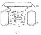
- Fig. 4 is a back view of the ATV;
- Fig. 5 is a cross-sectional view of an engine;
- Fig. 6 is a side view of the engine, partly in cross-section;
- Fig. 7 is a side view of the engine, partly in cross-section;
- Fig. 8 is a perspective view of a crankcase; and
- Fig. 9 is a constitutional explanatory drawing showing an electric system of the ATV.
- An ATV 10 is a four-wheel drive vehicle, which is suitable for agriculture, cattle breeding, hunting, transportation for security monitoring, or leisure. The ATV 10 includes a
vehicle frame 11. Anengine 12 is supported at the centre of thevehicle frame 11, a saddle-type seat 13 is supported above theengine 12, afuel tank 14 is supported in front of the saddle-type seat 13, and ahandlebar 14A is supported in front thereof. Thehandlebar 14A is provided with an accelerator lever 14A1, a brake lever 14A2, and a clutch lever 14A3 mounted thereon. - As shown in Fig. 2, a
front wheel 16 is rotatably supported on thevehicle frame 11 via a pair of left andright suspension mechanisms 15. As shown in Fig. 4, a rearswing arm assembly 18 is supported at the rear centre of thevehicle frame 11 via asuspension mechanism 17, and arear wheel 19 is supported by arear wheel shaft 18A of the rearswing arm assembly 18. Asprocket 18B is fixed to therear wheel shaft 18A, and as shown in Fig. 1, adrive chain 20 is wound between thesprocket 18B and afinal output shaft 27 of theengine 12. Abrake mechanism 21 is arranged on therear wheel shaft 18A. Thesprocket 18B and aguard member 18C for protecting thebrake mechanism 21 are mounted to the rearswing arm assembly 18. - As shown in Fig. 3, foot rests 22A, 22B for placing the feet are disposed on the left and right sides of the
vehicle frame 11, and the foot rests 22A, 22B are positioned between thefront wheel 16 and therear wheel 19. As shown in Fig. 1, the onefoot rest 22A is provided with a change pedal 22A1 for switching a transmission ratio of a gear speed change mechanism, described later, so as to be capable of pivotal movement, and theother foot rest 22B is provided with a brake pedal 22B1 for operating thebrake mechanism 21 described above so as to be capable of pivotal movement. In addition, as shown in Fig. 1 to Fig. 4, thevehicle frame 11 is provided with afront fender 23A for covering thefront wheel 16, arear fender 23B for covering therear wheel 19, afront guard 24A, arear guard 24B, a battery 25, anair cleaner 26, and so on mounted thereto. Therear guard 24B supports anexhaust muffler 28, and supports astorage case 29 having an openable andclosable lid 29A. - Fig. 5 is a cross-sectional view of the
engine 12 according to this embodiment. Theengine 12 is a four-cycle engine, and includes acylinder head 30, acylinder block 31, and acrankcase 32. Thecylinder block 31 is formed with acylinder 33, and thecylinder 33 is provided with apiston 34 so as to be capable of sliding movement. Thepiston 34 is connected to acrankshaft 40 via a connectingrod 35, and thecrankshaft 40 is journaled by thecrankcase 32. - The
cylinder head 30 is provided with an air-intake channel 30A and anexhaust channel 30B, and the respective channels include an air-intake valve 32A and anexhaust valve 32B. These valve bodies are configured to be capable of opening and closing an air-intake port 31A and an exhaust port (not shown) in communication with thecylinder 33. The air-intake valve 32A moves in the vertical direction to open and close the air-intake port 31A according to the cam profile of acam 33A, while theexhaust valve 32B moves in the vertical direction to open and close the exhaust port (not shown) via arocker arm 33B driven by thecam 33A. - In other words, as shown in Fig. 6, a
sprocket 41 is provided at the shaft end of acamshaft 34A which supports thecam 33A, and achain 42 is wound between thesprocket 41 and asprocket 40A fixed to the shaft end of thecrankshaft 40. Thechain 42 is provided with a tension via atensioner lifter 42A. - Then, the rotational force of the
crankshaft 40 is transmitted to thecamshaft 34A via thechain 42, whereby thecam 33A and therocker arm 33B rotate or pivot, and the air-intake valve 32A and theexhaust valve 32B move in the vertical direction, so that the air-intake and exhaust port are opened at a suitable timing according to the rotation of thecrankshaft 40. - As shown in Fig. 5, an
ignition plug 36 is disposed on thecylinder head 30, and a throttle body and a carburetor, not shown, are connected to the air-intake channel 30A. Combustion air is supplied via the throttle body and fuel to be mixed with combustion air at a suitable mixture ratio is supplied via the carburetor. Air-fuel mixture is taken into thecylinder 33, and then ignited by theignition plug 36, whereby an explosive power generated by ignition moves thepiston 34 in the vertical direction to rotate thecrankshaft 40. - The shaft end of the
crankshaft 40 is coaxially provided with an ACG (AC Generator) 43 as shown in Fig. 6. The ACG 43 generates power according to the rotation of thecrankshaft 40, and the power is supplied to electric equipment such as an ECU (Electric Control Unit) 201, described later, of thevehicle 10 and the like (see Fig. 9), and is used to charge a battery 204 (see Fig. 9). - In addition to the ACG 43, a
start clutch 50 including a centrifugal clutch mechanism and astarting gear 60 are coaxially disposed on thecrankshaft 40 as shown in Fig. 7. Although not shown, thestart clutch 50 mainly includes a clutch inner being connected to thecrankshaft 40 and having a clutch shoe, and a clutch outer for connecting the clutch by a frictional force generated when the clutch shoe of the clutch inner is pressed. When thecrankshaft 40 rotates, the clutch inner always rotates. When it rotates at a low number of revolutions per minute (idling), the clutch shoe does not come into press contact with the clutch outer, and hence the clutch inner runs idle. On the other hand, when the number of revolutions per minute of thecrankshaft 40 exceeds a predetermined value, the clutch shoe of the clutch inner is pressed against the clutch outer by its centrifugal force and hence the clutch is connected. - A
primary drive gear 51 is coaxially connected to the clutch outer of thestart clutch 50, and when the clutch is connected, the rotational force of thecrankshaft 40 is transmitted to theprimary drive gear 51 via thestart clutch 50. - A primary driven
gear 53 engages theprimary drive gear 51, and the primary drivengear 53 is disposed coaxially with amain shaft 45 which constitutes part of a constant-mesh gear speed change device described later. - In addition to the
start clutch 50, theengine 12 includes a speed-change clutch 70 having a number of frictional plates (not shown) as shown in Fig. 5, and the speed-change clutch 70 is disposed coaxially with themain shaft 45. - The speed-
change clutch 70 includes a clutch outer which rotates integrally with the primary driven gear 53 (Fig. 7), a clutch inner rotating integrally with themain shaft 45, the plurality of frictional plates disposed between the clutch outer and the clutch inner, and a clutch piston for pressing the frictional plates, although not shown, respectively. The speed-change clutch 70 moves the clutch piston to connect the clutch by bringing the clutch outer and the clutch inner into press contact with each other via the frictional plates. - In this arrangement, when the
start clutch 50 is connected, the rotational force of thecrankshaft 40 is transmitted to theprimary drive gear 51 and the primary drivengear 53, and then is transmitted to the clutch outer of the speed-change clutch 70 which is connected integrally with the drivengear 53. In this state, if the speed-change clutch 70 is not connected, the clutch outer of the speed-change clutch 70 runs idle, and the rotational force thereof is not transmitted to themain shaft 45. In contrast, when thestart clutch 50 is connected, and then the speed-change clutch 70 is connected, the rotational force of thecrankshaft 40 is transmitted to themain shaft 45 via theprimary drive gear 51, the primary drivengear 53, and the speed-change clutch 70. - In other words, in addition to the
crankshaft 40 and themain shaft 45, acounter shaft 46, ashift drum 47, and ashift fork 48 are supported in thecrankcase 32 as shown in Fig. 5. These constitute the constant-mesh gear speed change device, and the direction of travel and the transmission ratio are switched among five gears for forward movement and one gear for reverse movement. - In other words, a plurality of
gears 45A are connected on the shaft of themain shaft 45, and a plurality ofgears 46A engaging thegear 45A of themain shaft 45 are connected on the shaft of thecounter shaft 46. Then, by selectingarbitrary gears main shaft 45 is changed in speed by thegears counter shaft 46 according to the defined transmission ratio, then transmitted to thefinal output shaft 27 connected to thecounter shaft 46 via the gear or the like, and then outputted and transmitted to therear wheel 19 from thefinal output shaft 27 via thedrive chain 20 as a power force of theengine 12 as shown in Fig. 1. - Although not shown, the gear speed change devices 45-48 are provided with a reverse movement speed change gear, and when the reverse movement is selected, the
main shaft 45 and thecounter shaft 46 are connected via the reverse movement speed change gear. In this arrangement, the rotational force transmitted to themain shaft 45 via two clutch connections is shifted to the reverse movement gear, then transmitted to the final output shaft 27 (Fig. 1) via thecounter shaft 46, and then transmitted to therear wheel 19 from thefinal output shaft 27 via thedrive chain 20 as a power force of theengine 12. - Describing the forward movement speed change operation, connection of the speed-
change clutch 70 is released by the operation of the clutch lever 14A3 mounted to thehandlebar 14A, and power transmission to themain shaft 45 is disconnected. - Then, in the state in which power transmission to the
main shaft 45 is disconnected, the change pedal 22A1 (Fig. 1) mounted to thefoot rest 22A is pivoted. The change pedal 22A1 is connected to theshift drum 47, and when the change pedal 22A1 is pivoted, theshift drum 47 rotates, and the rotation moves ashift pin 48A engaged with a helical groove (not shown) of theshift drum 47 in the axial direction. Theshift pin 48A is integral with theshift fork 48, and when theshift pin 48A moves in the axial direction, theshift fork 48 slides in the axial direction, and theshift fork 48 moves any one of thegears 46A on thecounter shaft 46 in the axial direction, whereby thegear 46A and any one of thegears 45A on themain shaft 45 are engaged. - In this embodiment, as shown in Fig. 5 to Fig. 7, the
engine 12 is provided with astarter motor 100 for starting the engine mounted thereon. Theengine 12 is provided with thecrankcase 32 as shown in Fig. 8, and thecrankcase 32 is integrally moulded with amotor mount 101 formed by casting at the front part thereof. Thestarter motor 100 is cantilevered by themotor mount 101. Thecrankcase 32 includes afront engine mount 12A for fixing the front side of theengine 12 to thevehicle frame 11, and alower engine mount 12B for fixing the lower side of theengine 12 to thevehicle frame 11 both moulded integrally by casting, and themotor mount 101 is integrally moulded between thefront engine mount 12A and thelower engine mount 12B. - The
motor mount 101 is disposed at a position slightly shifted toward one side surface of thecrankcase 32 in the area between thefront engine mount 12A and thelower engine mount 12B, and is formed into a shape projecting obliquely forward. - The
motor mount 101 is, as shown in Fig. 7, a hollow in the interior thereof, and apinion gear 103 fixed to amotor shaft 102 of thestarter motor 100 is disposed therein. A transmission gear 104A engages thepinion gear 103, and atransmission gear 104B engages asmall gear 104C which is integral with the transmission gear 104A, and thetransmission gear 104B engages with the startinggear 60 connected to thecrankshaft 40. The startinggear 60 is connected to thecrankshaft 40 via a one-way clutch (not shown). The gear train described above constitutes atransmission mechanism 105 for transmitting a rotational force of thestarter motor 100 to thecrankshaft 40. - The one-way clutch (not shown) is a clutch which enables transmission of rotational force of the starting
gear 60 to thecrankshaft 40 as long as the number of revolutions per minute of the startinggear 60 exceeds the number of revolutions per minute of thecrankshaft 40. Instead of the one-way clutch, it is also possible to apply an electromagnetic pushing mechanism for moving thepinion gear 103 of thestarter motor 100 between the position to mesh with the transmission gear 104A and the position not to mesh therewith using, for example, a magnet switch. - In this structure, when the
starter motor 100 is started when starting theengine 12, thepinion gear 103 rotates, then the startinggear 60 rotates via the transmission gear 104A, thesmall gear 104C and thetransmission gear 104B, and hence thecrankshaft 40 engaged with the startinggear 60 via the one-way clutch (not shown) is driven. At this time, ignition control of theignition plug 36 is performed by the ECU, not shown, whereby theengine 12 is started. - When the
engine 12 is started, the clutch connection of thestart clutch 50 is released, and the power is not transmitted from thecrankshaft 40 to theprimary drive gear 51. - In other words, the
engine 12 can be started according to the start command operation in a state in which connection between thecrankshaft 40 and the speed-change clutch 70, and hence the constant-mesh gear speed change device, are disconnected with the start clutch 50 (centrifugal clutch). - The electric structure of the ATV in the embodiment will be described.
- Fig. 9 shows a structure of an electric system of the ATV.
- The electric system of the
ATV 10 includes theECU 201 for controlling an ignition system of the engine or the like, theACG 43 for generating an AC power in association with the rotation of thecrankshaft 40, a regulator-rectifier 203 having a three-phase full-wave rectification bridge circuit and a stabilizing circuit, not shown, for rectifying and stabilizing a generated output of theACG 43, abattery 204 for storing the DC power supplied from an ACG 202 via the regulator-rectifier 203 and supplying the DC power to the respective parts, and an ignitionkey switch 205 having a plurality of contact points and supplying power, which is supplied via the regulator-rectifier 203 when being closed (ON state) in conjunction with key operation of the rider. - The electric system of the
ATV 10 further includes afuse box 206 provided with a plurality of fuses for preventing excess current from being supplied to the respective parts directly from the regulator-rectifier 203 or from the regulator-rectifier 203 via the ignitionkey switch 205, thestarter motor 100 which is connected to thebattery 204 when astart switch 207 is brought into a closed state by the operation of the rider when starting the engine and thestarter magnet switch 208 is driven and brought into the closed state, and which rotates thecrankshaft 40, and ashift switch 210 which is interlocked with the operation of the change pedal 22A1 and hence the position of theshift drum 47. It also includes adiode box 211 which is provided with a plurality of reverse current blocking diodes, is interlocked with theshift switch 210, generates a gear position detection signal S GP, branches off the gear position detection signal S GP and outputs as a gear position display signal S GPD and a gear position control signal S GPC (which is equivalent to the engine start control signal), as well as acondition display unit 212 provided with a plurality of LEDs for displaying the various conditions, a CPU 213 for controlling theentire ATV 10, a lamp/horn unit 214 for turning on and off various lamps such as a front lamp and driving an alarm unit (horn) under control of the CPU 231, and astop switch 215 which is interlocked with the operation of the brake. - In the structure described above, the
ECU 201 is connected to athrottle sensor 221 for detecting the throttle opening, afan motor 222 for driving a radiator fan, akill switch 223 for stopping the engine in case of emergency, apulse generator 224 for generating pulses which correspond to the reference ignition timing, a coolingwater temperature sensor 225 for detecting the temperature of cooling water, an ignition coil 226 for generating a high voltage for igniting the engine, arotor angle sensor 227 for detecting the rotor angle, and hence the crank angle of theACG 43, and afuel sensor 228 for detecting the amount of fuel. - The
shift switch 210 is a change-over switch including seven contact points and one movable section, and the contact points correspond to a forward first gear, a forward second gear, a forward third gear, a forward fourth gear, a forward fifth gear, a reverse gear, and the neutral position, respectively. - The
diode box 211 includes six diodes DN, D1-D5, which correspond to the gear positions; the neutral position, the forward first gear, the forward second gear, the forward third gear, the forward fourth gear, the forward fifth gear, respectively. - The electric connection among the
ECU 201, the seven contact points constituting theshift switch 210, the diodes constituting thediode box 211, and the CPU will now be described in detail. - The
ECU 201 includes astop switch terminal 201A which is connected, to thestop switch 215 and serves as a current supply terminal for generating a gear position detection signal, and an anode terminal of the diode DN which constitutes thediode box 211 is directly connected to thestop switch terminal 201A. Anode terminals of the diodes D1-D5 are commonly connected also to thestop switch terminal 201A via thestop switch 215. - A cathode terminal of the diode DN is connected to a neutral detection terminal TN of the
ECU 201 and a corresponding contact point of theshift switch 210. In the same manner, the cathode terminals of the diodes D1-D5 are connected to a gear position display input terminal of theECU 201 and corresponding contact points of the shift switches 210. The respective cathode terminals of the diodes D1-D5 are connected to the CPU 213. - The contact point corresponding to the reverse movement which constitutes the
shift switch 210 is connected to a reverse movement detection terminal of theECU 201, and is connected to the regulator-rectifier 203 via the LED which constitutes thecondition display unit 212, thefuse box 206, and theignition switch 205. - Connected between the CPU 213 and the
ECU 201 is a control line LC which is used by the CPU 213 for controlling theECU 201. - In the description below, the output signals from the diodes D1-D5 constituting the
diode box 211 are referred to as the gear position detection signal S GP for the sake of convenience, the signal which is branched off from the gear position detection signal S GP in thediode box 211 and reaches the gear position display input terminal of theECU 201 is referred to as the gear position display signal S GPD, and the signal which is branched off from the gear position detection signal S GP in thediode box 211 and reaches the CPU 213 is referred to as the gear position control signal S GPC. - Subsequently, the engine ignition control operation will be described.
- When the
kill switch 223 is in the closed state (ON state), the rider inserts the key, and then theignition switch 205 is turned ON in association with the key operation. - When the rider operates the
start switch 207 to the closed state (ON state) in this state, thestarter magnet switch 208 is driven and brought into the closed state, so that thestarter motor 100 is connected to thebattery 204. - Consequently, the
starter motor 100 is driven, thepinion gear 103 rotates, thestart gear 60 rotates via the transmission gear 104A, asmall gear 104C and thetransmission gear 104B, and thecrankshaft 40 which is integral therewith is rotated at a number of revolutions per minute smaller than the number of revolutions per minute at idling. - In this state, the CPU 213 controls ignition.
- The control of the CPU 213 will now be described in detail.
- When the
shift drum 47 is in a state corresponding to the neutral position of the gear by the operation of the change pedal 22A1 by the rider, the movable section constituting theshift switch 210 is electrically connected to the contact point corresponding to the neutral position (shown by N in the drawing) out of the seven contact points. - Consequently, the cathode terminal of the diode DN is connected to an engine earth EE and a frame earth FE having the same potential (which is equivalent to "L" level) via the corresponding contact point of the
shift switch 210. - Therefore, a current is supplied from the
stop switch terminal 201A of theECU 201 to the diode DN, and the current flows through the engine earth EE and the frame earth FE, and hence the potential level at the cathode terminal of the diode DN becomes "L" level (which is equivalent to the potential level of the engine earth and the frame earth FE). - Accordingly, the neutral detection terminal TN of the
ECU 201 also becomes "L" level, and theECU 201 determines that the engine start conditions are satisfied without waiting for the control of the CPU 213. - Therefore, the
ECU 201 which determines that the engine start conditions are satisfied controls the ignition coil 226 based on the pulse corresponding to the reference ignition timing generated by thepulse generator 224 and the crank angle corresponding to the output of therotor angle sensor 227, and applies a high voltage for ignition to the ignition plug 36 connected to the secondary side of the ignition coil 226. - Accordingly, discharge between a centre electrode and a ground electrode of the
ignition plug 36 is effected, so that air-fuel mixture supplied to a cylinder via a carburetor, not shown, is ignited, thereby completing the engine start. - When the
engine 12 is started, the number of revolutions per minute of thecrankshaft 40 increases to the number of revolutions per minute at idling. The startinggear 60 is provided on thecrankshaft 40 via a one-way clutch, and hence when the number of revolutions per minute of the startinggear 60 exceeds the number of revolutions per minute of thecrankshaft 40, the startinggear 60 and thecrankshaft 40 are connected, and when the number of revolutions per minute of the startinggear 60 runs under the number of revolutions per minute of thecrankshaft 40, the startinggear 60 and thecrankshaft 40 are disconnected, whereby the startinggear 60 runs idle. Therefore, even when theengine 12 is started, since the number of revolutions per minute of the startinggear 60 runs under the number of revolutions per minute of thecrankshaft 40, the startinggear 60 and thecrankshaft 40 are disconnected after having started the engine. Therefore, when thestarter motor 100 is driven after having started the engine, therespective gears transmission mechanism 105 run idle. - When the
engine 12 starts, the clutch connection of thestart clutch 50 is released, and hence the power is not transmitted from thecrankshaft 40 to theprimary drive gear 51. - In other words, the start clutch 50 which serves as a centrifugal clutch can start the engine in a state in which connection between the
crankshaft 40 and the aforementioned speed-change clutch 70, and hence the connection with the aforementioned constant-mesh gear speed change device (transmission) is disconnected. - When the
shift drum 47 is under the condition corresponding to the forward first gear to the forward fifth gear of the gear by the operation of the change pedal 22A1 by the rider, the movable section which constitutes theshift switch 210 is electrically connected to the contact point which corresponds to any one of the forward first gear to the forward fifth gear (shown by 1 to 5 in the drawing) out of the seven contact points. - Consequently, the cathode terminal of the diode DX (X=1-5) corresponding to the forward gear position is connected to the engine earth EE and the frame earth FE having the same potential via the corresponding contact points and the movable section of the
shift switch 210. - Therefore, the current is supplied from the
stop switch terminal 201A of theECU 201 via thestop switch 215 to the diode DX, and the current flows to the engine earth EE and the frame earth FE, and hence the potential level of the cathode terminal of the diode DX becomes "L" level (which is equivalent to the potential level of the engine earth and the frame earth FE). In other words, gear position detection signal S GPX (X=1-5) corresponding to the forward gear position is at "L" level, and gear position display signal S GPDX (X=1-5) and gear position control signal S GPCX (X=1-5) branched off therefrom are also at "L" level. - At this time, since the cathode terminals of the diodes DY (Y=1-5, and Y≠X) which correspond to the unselected forward gear positions are not connected to the engine earth EE and the frame earth FE, the corresponding gear position detection signals S GPY (Y=1-5, and Y≠X) become "H" level (which is equivalent to the potential level of the
stop switch terminal 201A of theECU 201, more precisely, the potential level of thestop switch terminal 201A in which the amount of voltage drop of the diode is taken into account), and hence gear position display signals S GPDY (Y=1-5, and Y≠X) and gear position control signals S GPCY (Y=1-5 and Y≠X) branched off therefrom are also at "H" level. - More specifically, when the
shift drum 47 is in the state corresponding to a forward third gear position by the operation of the change pedal 22A1, a gear position detection signal S GP3 becomes "L" level, and a gear position display signal S GPD3 and a gear position control signal S GPC3 branched off therefrom are also at the "L" level. On the other hand, gear position detection signals S GP1, S GP2, S GP4, S GP5 are at "H" level, and gear position display signals S GPD1, S GPD2, S GPD4, S GPD5 which are branched off and outputted to theECU 201 and gear position control signals S GPC1, S GPC2, S GPC4, S GPC5 which are outputted to the CPU 213 are also at "H" level. - Consequently, when only one of the gear position control signals S GPCX (X=1-5) to the CPU 213 becomes "L" level, it is determined that the gear position is the forward gear position, and the brake is being applied, and hence an instruction to permit ignition is sent to the
ECU 201 via the control line LC. - Accordingly, the
ECU 201 controls the ignition coil 226 based on the pulse corresponding to the reference ignition timing generated by thepulse generator 224 and on the crank angle corresponding to the output of therotor angle sensor 227, and applies a high voltage for ignition to the ignition plug 36 connected to the secondary side of the ignition coil 226. - Accordingly, discharge between the centre electrode and the earth electrode of the
ignition plug 36 is effected, and air-fuel mixture supplied into the cylinder via a carburetor, not shown, is ignited, thereby completing the engine start. - When the
engine 12 starts, the number of revolutions per minute of thecrankshaft 40 increases to the number of revolutions per minute at idle. The startinggear 60 is provided on thecrankshaft 40 via the one-way clutch, and hence when the number of revolutions per minute of the startinggear 60 exceeds the number of revolutions per minute of thecrankshaft 40, the startinggear 60 and thecrankshaft 40 are connected, and when the number of revolutions per minute of the startinggear 60 runs under the number of revolutions per minute of thecrankshaft 40, the startinggear 60 and thecrankshaft 40 are disconnected and the startinggear 60 runs idle. Therefore, even when theengine 12 starts, since the number of revolutions per minute of the startinggear 60 runs under the number of revolutions per minute of thecrankshaft 40, the startinggear 60 and thecrankshaft 40 are disconnected after having started the engine. Therefore, when thestarter motor 100 is driven after having started the engine, therespective gears transmission mechanism 105 run idle. - When the
engine 12 starts, the clutch connection of thestart clutch 50 is released, and the power is not transmitted from thecrankshaft 40 to theprimary drive gear 51. - In other words, the start clutch 50 which functions as a centrifugal clutch can start the engine in a state in which the
crankshaft 40 and the aforementioned speed-change clutch 70, and hence the aforementioned constant-mesh gear speed change device (transmission), are disconnected. - In other words, when the gear position is at the forward gear position and the brake is operated to bring the stop switch into the closed state (ON state), the engine can be started immediately. Therefore, even when the engine is stopped while climbing the uphill, the vehicle can be started again easily and quickly without sudden acceleration.
- On the other hand, since only the gear position display signal S GPD3 out of the input gear position display signals S GPD is at the "L" level, the
ECU 201 turns on a gear position display lamp, which corresponds to the forward third gear, not shown, to notify the rider that the gear is now at the forward third gear position. - In contrast to the above-described operation, when all the gear position control signals S GPCX (X=1-5) are in the high-impedance state, the CPU 213 determines that the
stop switch 215 is in the opened state (OFF state), and the brake is not applied, and hence sends an instruction to prohibit ignition except for the case where the gear is at the neutral position to theECU 201 via the control line LC. - When all the gear position control signals S GPCX (X=1-5) are at the "H" level, the CPU 213 determines that the brake is operated, but the gear is not at the forward gear position.
- When the
shift drum 47 is in a state corresponding to the reverse position of the gear by the operation of the change pedal 22A1 of the rider, the movable section which constitutes theshift switch 210 is electrically connected to the contact point which corresponds to the reverse position (represented by R in the drawing) out of the seven contact points. - Consequently, a reverse movement detection terminal TR of the
ECU 201 is connected to the engine earth EE and the frame earth FE via theshift switch 210, and the potential level of the reverse movement detection terminal TR becomes "L" level (which is equivalent to the potential level of the engine earth and the frame earth FE). - Therefore, the
ECU 201 determines that the engine start conditions are not satisfied without waiting for the control of the CPU 213, and goes into a waiting state, in which the ignition is prohibited. - As described thus far, according to this embodiment, when the engine stops, the engine can be started easily and quickly in a state in which the crankshaft and the transmission are disconnected by the centrifugal clutch when the gear is at the neutral position and the forward gear position (in the example described above, the forward first to fifth gears).
- Although description has been made regarding a speed change device having five forward gears and one reverse gear thus far, the invention is not limited thereto, and the speed change device can have an arbitrary number of gears.
- Although description has been made regarding the case in which the gear is at the position corresponding to the case where the gear position detection signal S GP, the gear position display signal S GPD, and the gear position control signal S GPC are at "L" level, the invention is not limited thereto, and the circuit can be configured to cause the gear to be at the position corresponding to the case in which the gear position detection signal S GP, the gear position display signal S GPD, and the gear position control signal S GPC are at "H" level.
Claims (4)
- An engine starting apparatus for an all-terrain traveling vehicle in which an engine is started by an engine start command operation comprising:a centrifugal clutch for transmitting a rotational force of a crankshaft to a transmission when the number of revolutions per minute of the crankshaft of the engine reaches a predetermined number of revolutions per minute;a gear position detecting unit for detecting the gear position of the transmission; anda controller which enables starting of the engine according to the start command operation in a state in which the crankshaft and the transmission is disconnected by the centrifugal clutch when the gear position is at the neutral position and the forward gear position based on the result of detection of the gear position detecting unit.
- An engine starting apparatus as claimed in claim 1, characterized in that the controller is adapted to start the engine according to the start command operation when the gear position is the forward gear position, a brake is operated, and a stop switch is in the closed state.
- An engine starting apparatus as claimed in claim 1 or claim 2, characterized in that the controller may be adapted to prohibit the engine start when the gear position detected by the gear position detecting unit is the reverse gear position.
- An engine starting apparatus as claimed in any one of claims 1 to 3, characterized in that the gear position detecting unit comprises:a shift switch having a plurality of contact points opened and closed according to the gear position of the transmission anda diode box having a plurality of diodes which are electrically connected to the contact points and cause a gear position detection signal to be branched off to an engine start control signal and a gear position display signal in the subsequent stage of the diode in cooperation with the shift switch, together with producing the gear position detection signal.
Applications Claiming Priority (1)
| Application Number | Priority Date | Filing Date | Title |
|---|---|---|---|
| JP2004190730A JP4262149B2 (en) | 2004-06-29 | 2004-06-29 | Engine starting device for rough terrain vehicle |
Publications (2)
| Publication Number | Publication Date |
|---|---|
| EP1612409A2 true EP1612409A2 (en) | 2006-01-04 |
| EP1612409A3 EP1612409A3 (en) | 2007-05-30 |
Family
ID=34941642
Family Applications (1)
| Application Number | Title | Priority Date | Filing Date |
|---|---|---|---|
| EP05253592A Ceased EP1612409A3 (en) | 2004-06-29 | 2005-06-10 | Engine starting apparatus for all-terrain vehicle (ATV) |
Country Status (8)
| Country | Link |
|---|---|
| US (1) | US7300382B2 (en) |
| EP (1) | EP1612409A3 (en) |
| JP (1) | JP4262149B2 (en) |
| CN (1) | CN100575695C (en) |
| AU (1) | AU2005201913B2 (en) |
| BR (1) | BRPI0502470A (en) |
| CA (1) | CA2508557C (en) |
| TW (1) | TWI283279B (en) |
Cited By (1)
| Publication number | Priority date | Publication date | Assignee | Title |
|---|---|---|---|---|
| EP4074958A1 (en) * | 2021-03-25 | 2022-10-19 | Suzuki Motor Corporation | Operation stop control device, electrical system for straddle-type vehicle, and switch discrimination method |
Families Citing this family (22)
| Publication number | Priority date | Publication date | Assignee | Title |
|---|---|---|---|---|
| US20060191261A1 (en) * | 2003-07-08 | 2006-08-31 | Bailey Rudolph V Sr | Gasoline to pneumatic engine conversion zero emission & fuel cost |
| CA2502131C (en) * | 2004-03-30 | 2011-12-20 | Honda Motor Co., Ltd. | Independent vehicle suspension with stabilizer |
| US7380805B1 (en) * | 2004-12-08 | 2008-06-03 | Asian Ventures, Inc. | Go-cart |
| US7687999B2 (en) * | 2006-01-06 | 2010-03-30 | Dale Essick | Emergency indicator light for vehicle pennant |
| JP4578410B2 (en) * | 2006-01-16 | 2010-11-10 | ヤンマー株式会社 | Work vehicle front guard |
| JP4897534B2 (en) * | 2007-03-28 | 2012-03-14 | 本田技研工業株式会社 | Vehicle transmission |
| US8157250B2 (en) * | 2008-10-23 | 2012-04-17 | GM Global Technology Operations LLC | Hydraulic mount having double idle rate dip frequencies of dynamic stiffness |
| US8414455B2 (en) * | 2009-04-03 | 2013-04-09 | Gm Global Technology Operations, Llc | Vehicle systems and methods of operating vehicle systems |
| US8342285B2 (en) | 2010-10-14 | 2013-01-01 | GM Global Technology Operations LLC | Fully decoupled hydraulic torque strut |
| US8789633B2 (en) * | 2012-12-07 | 2014-07-29 | Honda Motor Co., Ltd. | Vehicle including intake assembly having snorkel |
| TW201607792A (en) * | 2014-08-29 | 2016-03-01 | Kwang Yang Motor Co | Coupling structure of dynamic and power supply for multipurpose vehicle |
| JP6322111B2 (en) * | 2014-09-30 | 2018-05-09 | 本田技研工業株式会社 | Vehicle transmission |
| US9759313B2 (en) | 2014-11-26 | 2017-09-12 | Polaris Industries Inc. | Electronic shifting of a transmission |
| US9746070B2 (en) * | 2014-11-26 | 2017-08-29 | Polaris Industries Inc. | Electronic control of a transmission |
| CN110382856B (en) * | 2017-01-30 | 2021-07-27 | 庞巴迪动力产品公司 | Vehicles with Air Filter Access Panel |
| US10443714B2 (en) | 2017-06-29 | 2019-10-15 | GM Global Technology Operations LLC | Systems and methods for controlling a transmission and an engine with a combination park and ignition switch |
| US10619615B2 (en) * | 2017-10-03 | 2020-04-14 | Polaris Industries Inc. | Crankcase mounts and reinforced rubber in mount on force vector |
| US12208854B2 (en) | 2022-02-15 | 2025-01-28 | Arctic Cat Inc. | Snowmobile frame |
| US12503200B2 (en) | 2022-02-16 | 2025-12-23 | Arctic Cat Inc. | Recoil housing, engine assembly, and method of assembling engine assembly |
| US11958362B1 (en) | 2022-11-21 | 2024-04-16 | Honda Motor Co., Ltd. | All-terrain vehicle assembly with bed outlet and method for powering the same |
| USD1063697S1 (en) | 2023-03-07 | 2025-02-25 | Arctic Cat Inc. | Rear kick-up for a snow vehicle |
| USD1082637S1 (en) | 2023-03-07 | 2025-07-08 | Arctic Cat Inc. | Running board for a snow vehicle |
Citations (3)
| Publication number | Priority date | Publication date | Assignee | Title |
|---|---|---|---|---|
| JPS604432A (en) * | 1983-06-21 | 1985-01-10 | Honda Motor Co Ltd | Vehicle starting control device |
| JPS61167166A (en) | 1985-01-20 | 1986-07-28 | Yamaha Motor Co Ltd | Starter for vehicle equipped with centrifugal clutch |
| JPH05209584A (en) | 1991-07-18 | 1993-08-20 | Eaton Corp | Engine start of electronic control car and its device |
Family Cites Families (8)
| Publication number | Priority date | Publication date | Assignee | Title |
|---|---|---|---|---|
| JPS62255572A (en) * | 1986-04-30 | 1987-11-07 | Suzuki Motor Co Ltd | Starting device for 3 or 4 wheel vehicle traveling on unleveled ground |
| JPH0711219B2 (en) * | 1992-05-18 | 1995-02-08 | 株式会社城南製作所 | Automotive wind regulator |
| JPH0953551A (en) * | 1995-08-11 | 1997-02-25 | Jatco Corp | Starter control device |
| JP2002285941A (en) * | 2001-03-26 | 2002-10-03 | Kawasaki Heavy Ind Ltd | Starting device for four-wheeled off-road vehicle and riding type four-wheeled off-road vehicle equipped therewith |
| WO2002101258A2 (en) * | 2001-06-13 | 2002-12-19 | Luk Lamellen Und Kupplungsbau Beteiligungs Kg | Clutch actuation device and methods for determining clutch parameters |
| EP1302359B1 (en) * | 2001-10-13 | 2006-06-07 | Ford Global Technologies, LLC | Vehicle engine automatic start/stop control method |
| US6880687B2 (en) * | 2003-05-30 | 2005-04-19 | Eaton Corporation | Transmission system and method of operation to accomodate engagement of centrifugal clutch |
| US20050023050A1 (en) * | 2003-07-30 | 2005-02-03 | Craig Chidlow | Portable motorized trailer dolly |
-
2004
- 2004-06-29 JP JP2004190730A patent/JP4262149B2/en not_active Expired - Fee Related
-
2005
- 2005-04-19 TW TW094112428A patent/TWI283279B/en not_active IP Right Cessation
- 2005-05-05 AU AU2005201913A patent/AU2005201913B2/en not_active Ceased
- 2005-05-24 CN CN200510073785A patent/CN100575695C/en not_active Expired - Fee Related
- 2005-05-27 CA CA002508557A patent/CA2508557C/en not_active Expired - Fee Related
- 2005-06-10 EP EP05253592A patent/EP1612409A3/en not_active Ceased
- 2005-06-27 US US11/167,901 patent/US7300382B2/en not_active Expired - Lifetime
- 2005-06-27 BR BRPI0502470-6A patent/BRPI0502470A/en not_active Application Discontinuation
Patent Citations (3)
| Publication number | Priority date | Publication date | Assignee | Title |
|---|---|---|---|---|
| JPS604432A (en) * | 1983-06-21 | 1985-01-10 | Honda Motor Co Ltd | Vehicle starting control device |
| JPS61167166A (en) | 1985-01-20 | 1986-07-28 | Yamaha Motor Co Ltd | Starter for vehicle equipped with centrifugal clutch |
| JPH05209584A (en) | 1991-07-18 | 1993-08-20 | Eaton Corp | Engine start of electronic control car and its device |
Cited By (1)
| Publication number | Priority date | Publication date | Assignee | Title |
|---|---|---|---|---|
| EP4074958A1 (en) * | 2021-03-25 | 2022-10-19 | Suzuki Motor Corporation | Operation stop control device, electrical system for straddle-type vehicle, and switch discrimination method |
Also Published As
| Publication number | Publication date |
|---|---|
| AU2005201913A1 (en) | 2006-01-12 |
| AU2005201913B2 (en) | 2011-04-07 |
| US20050288151A1 (en) | 2005-12-29 |
| EP1612409A3 (en) | 2007-05-30 |
| JP2006009742A (en) | 2006-01-12 |
| CA2508557A1 (en) | 2005-12-29 |
| CN100575695C (en) | 2009-12-30 |
| BRPI0502470A (en) | 2008-01-02 |
| TW200602555A (en) | 2006-01-16 |
| TWI283279B (en) | 2007-07-01 |
| US7300382B2 (en) | 2007-11-27 |
| CN1715639A (en) | 2006-01-04 |
| JP4262149B2 (en) | 2009-05-13 |
| CA2508557C (en) | 2008-11-18 |
Similar Documents
| Publication | Publication Date | Title |
|---|---|---|
| CA2508557C (en) | Engine starting apparatus for all-terrain traveling vehicle | |
| US9499042B2 (en) | Hybrid vehicle drivetrain | |
| US6218804B1 (en) | Vehicle including engine stopping/starting control unit | |
| US7303504B2 (en) | Power switchover apparatus for a hybrid vehicle | |
| EP2687705B1 (en) | Engine control apparatus, and engine control method | |
| EP2255987A1 (en) | Hybrid vehicle | |
| CA2508971C (en) | Shift control apparatus for continuously variable transmission | |
| EP1046813B1 (en) | Engine starter | |
| US7487855B2 (en) | Engine control method and apparatus including a tilt angle sensor | |
| JP2005113714A (en) | Blow-by gas control device for internal combustion engine | |
| US7351173B2 (en) | Transmission controller for continuously variable transmission system | |
| US7284523B2 (en) | Arrangement structure of starter motor | |
| KR100347859B1 (en) | Automatic two-wheeled vehicle | |
| ES2207379B1 (en) | MOTOR STARTING SYSTEM FOR VEHICLE. | |
| ITTO20000291A1 (en) | STARTING DEVICE FOR AN ENGINE. | |
| JP7019871B2 (en) | Straddle vehicle | |
| JP4211601B2 (en) | Engine start control device | |
| JP2000303853A (en) | 4 cycle engine | |
| EP2256336B1 (en) | Motorcycle | |
| JP2000283012A (en) | Engine starter | |
| JP2020070913A (en) | Swing unit | |
| JP6097465B2 (en) | Saddle riding vehicle | |
| JPS61167166A (en) | Starter for vehicle equipped with centrifugal clutch |
Legal Events
| Date | Code | Title | Description |
|---|---|---|---|
| PUAI | Public reference made under article 153(3) epc to a published international application that has entered the european phase |
Free format text: ORIGINAL CODE: 0009012 |
|
| AK | Designated contracting states |
Kind code of ref document: A2 Designated state(s): AT BE BG CH CY CZ DE DK EE ES FI FR GB GR HU IE IS IT LI LT LU MC NL PL PT RO SE SI SK TR |
|
| AX | Request for extension of the european patent |
Extension state: AL BA HR LV MK YU |
|
| PUAL | Search report despatched |
Free format text: ORIGINAL CODE: 0009013 |
|
| AK | Designated contracting states |
Kind code of ref document: A3 Designated state(s): AT BE BG CH CY CZ DE DK EE ES FI FR GB GR HU IE IS IT LI LT LU MC NL PL PT RO SE SI SK TR |
|
| AX | Request for extension of the european patent |
Extension state: AL BA HR LV MK YU |
|
| 17P | Request for examination filed |
Effective date: 20071130 |
|
| AKX | Designation fees paid |
Designated state(s): ES GB PT |
|
| REG | Reference to a national code |
Ref country code: DE Ref legal event code: 8566 |
|
| 17Q | First examination report despatched |
Effective date: 20081210 |
|
| STAA | Information on the status of an ep patent application or granted ep patent |
Free format text: STATUS: THE APPLICATION HAS BEEN REFUSED |
|
| 18R | Application refused |
Effective date: 20131015 |