EP1612388A2 - Apparatus For Controlling Throttle Valve Of Internal Combustion Engine - Google Patents
Apparatus For Controlling Throttle Valve Of Internal Combustion Engine Download PDFInfo
- Publication number
- EP1612388A2 EP1612388A2 EP05105565A EP05105565A EP1612388A2 EP 1612388 A2 EP1612388 A2 EP 1612388A2 EP 05105565 A EP05105565 A EP 05105565A EP 05105565 A EP05105565 A EP 05105565A EP 1612388 A2 EP1612388 A2 EP 1612388A2
- Authority
- EP
- European Patent Office
- Prior art keywords
- opening degree
- throttle valve
- voltage
- output voltage
- motor
- Prior art date
- Legal status (The legal status is an assumption and is not a legal conclusion. Google has not performed a legal analysis and makes no representation as to the accuracy of the status listed.)
- Withdrawn
Links
Images


Classifications
-
- F—MECHANICAL ENGINEERING; LIGHTING; HEATING; WEAPONS; BLASTING
- F02—COMBUSTION ENGINES; HOT-GAS OR COMBUSTION-PRODUCT ENGINE PLANTS
- F02D—CONTROLLING COMBUSTION ENGINES
- F02D11/00—Arrangements for, or adaptations to, non-automatic engine control initiation means, e.g. operator initiated
- F02D11/06—Arrangements for, or adaptations to, non-automatic engine control initiation means, e.g. operator initiated characterised by non-mechanical control linkages, e.g. fluid control linkages or by control linkages with power drive or assistance
- F02D11/10—Arrangements for, or adaptations to, non-automatic engine control initiation means, e.g. operator initiated characterised by non-mechanical control linkages, e.g. fluid control linkages or by control linkages with power drive or assistance of the electric type
- F02D11/105—Arrangements for, or adaptations to, non-automatic engine control initiation means, e.g. operator initiated characterised by non-mechanical control linkages, e.g. fluid control linkages or by control linkages with power drive or assistance of the electric type characterised by the function converting demand to actuation, e.g. a map indicating relations between an accelerator pedal position and throttle valve opening or target engine torque
-
- F—MECHANICAL ENGINEERING; LIGHTING; HEATING; WEAPONS; BLASTING
- F02—COMBUSTION ENGINES; HOT-GAS OR COMBUSTION-PRODUCT ENGINE PLANTS
- F02D—CONTROLLING COMBUSTION ENGINES
- F02D41/00—Electrical control of supply of combustible mixture or its constituents
- F02D41/20—Output circuits, e.g. for controlling currents in command coils
-
- F—MECHANICAL ENGINEERING; LIGHTING; HEATING; WEAPONS; BLASTING
- F02—COMBUSTION ENGINES; HOT-GAS OR COMBUSTION-PRODUCT ENGINE PLANTS
- F02D—CONTROLLING COMBUSTION ENGINES
- F02D41/00—Electrical control of supply of combustible mixture or its constituents
- F02D41/24—Electrical control of supply of combustible mixture or its constituents characterised by the use of digital means
- F02D41/2406—Electrical control of supply of combustible mixture or its constituents characterised by the use of digital means using essentially read only memories
- F02D41/2425—Particular ways of programming the data
- F02D41/2429—Methods of calibrating or learning
- F02D41/2451—Methods of calibrating or learning characterised by what is learned or calibrated
- F02D41/2464—Characteristics of actuators
-
- F—MECHANICAL ENGINEERING; LIGHTING; HEATING; WEAPONS; BLASTING
- F02—COMBUSTION ENGINES; HOT-GAS OR COMBUSTION-PRODUCT ENGINE PLANTS
- F02D—CONTROLLING COMBUSTION ENGINES
- F02D11/00—Arrangements for, or adaptations to, non-automatic engine control initiation means, e.g. operator initiated
- F02D11/06—Arrangements for, or adaptations to, non-automatic engine control initiation means, e.g. operator initiated characterised by non-mechanical control linkages, e.g. fluid control linkages or by control linkages with power drive or assistance
- F02D11/10—Arrangements for, or adaptations to, non-automatic engine control initiation means, e.g. operator initiated characterised by non-mechanical control linkages, e.g. fluid control linkages or by control linkages with power drive or assistance of the electric type
- F02D2011/101—Arrangements for, or adaptations to, non-automatic engine control initiation means, e.g. operator initiated characterised by non-mechanical control linkages, e.g. fluid control linkages or by control linkages with power drive or assistance of the electric type characterised by the means for actuating the throttles
- F02D2011/102—Arrangements for, or adaptations to, non-automatic engine control initiation means, e.g. operator initiated characterised by non-mechanical control linkages, e.g. fluid control linkages or by control linkages with power drive or assistance of the electric type characterised by the means for actuating the throttles at least one throttle being moved only by an electric actuator
-
- F—MECHANICAL ENGINEERING; LIGHTING; HEATING; WEAPONS; BLASTING
- F02—COMBUSTION ENGINES; HOT-GAS OR COMBUSTION-PRODUCT ENGINE PLANTS
- F02D—CONTROLLING COMBUSTION ENGINES
- F02D41/00—Electrical control of supply of combustible mixture or its constituents
- F02D41/20—Output circuits, e.g. for controlling currents in command coils
- F02D2041/2003—Output circuits, e.g. for controlling currents in command coils using means for creating a boost voltage, i.e. generation or use of a voltage higher than the battery voltage, e.g. to speed up injector opening
-
- F—MECHANICAL ENGINEERING; LIGHTING; HEATING; WEAPONS; BLASTING
- F02—COMBUSTION ENGINES; HOT-GAS OR COMBUSTION-PRODUCT ENGINE PLANTS
- F02D—CONTROLLING COMBUSTION ENGINES
- F02D41/00—Electrical control of supply of combustible mixture or its constituents
- F02D41/20—Output circuits, e.g. for controlling currents in command coils
- F02D2041/202—Output circuits, e.g. for controlling currents in command coils characterised by the control of the circuit
- F02D2041/2024—Output circuits, e.g. for controlling currents in command coils characterised by the control of the circuit the control switching a load after time-on and time-off pulses
- F02D2041/2027—Control of the current by pulse width modulation or duty cycle control
-
- F—MECHANICAL ENGINEERING; LIGHTING; HEATING; WEAPONS; BLASTING
- F02—COMBUSTION ENGINES; HOT-GAS OR COMBUSTION-PRODUCT ENGINE PLANTS
- F02D—CONTROLLING COMBUSTION ENGINES
- F02D41/00—Electrical control of supply of combustible mixture or its constituents
- F02D41/20—Output circuits, e.g. for controlling currents in command coils
- F02D2041/202—Output circuits, e.g. for controlling currents in command coils characterised by the control of the circuit
- F02D2041/2051—Output circuits, e.g. for controlling currents in command coils characterised by the control of the circuit using voltage control
-
- F—MECHANICAL ENGINEERING; LIGHTING; HEATING; WEAPONS; BLASTING
- F02—COMBUSTION ENGINES; HOT-GAS OR COMBUSTION-PRODUCT ENGINE PLANTS
- F02D—CONTROLLING COMBUSTION ENGINES
- F02D41/00—Electrical control of supply of combustible mixture or its constituents
- F02D41/20—Output circuits, e.g. for controlling currents in command coils
- F02D2041/2068—Output circuits, e.g. for controlling currents in command coils characterised by the circuit design or special circuit elements
- F02D2041/2072—Bridge circuits, i.e. the load being placed in the diagonal of a bridge to be controlled in both directions
-
- F—MECHANICAL ENGINEERING; LIGHTING; HEATING; WEAPONS; BLASTING
- F02—COMBUSTION ENGINES; HOT-GAS OR COMBUSTION-PRODUCT ENGINE PLANTS
- F02D—CONTROLLING COMBUSTION ENGINES
- F02D2200/00—Input parameters for engine control
- F02D2200/02—Input parameters for engine control the parameters being related to the engine
- F02D2200/04—Engine intake system parameters
- F02D2200/0404—Throttle position
-
- F—MECHANICAL ENGINEERING; LIGHTING; HEATING; WEAPONS; BLASTING
- F02—COMBUSTION ENGINES; HOT-GAS OR COMBUSTION-PRODUCT ENGINE PLANTS
- F02D—CONTROLLING COMBUSTION ENGINES
- F02D2200/00—Input parameters for engine control
- F02D2200/60—Input parameters for engine control said parameters being related to the driver demands or status
- F02D2200/602—Pedal position
Definitions
- the present invention relates to a throttle valve controlling apparatus of a motor drive type for opening/closing-driving a throttle valve of an internal combustion engine through a DC (direct current) motor.
- an accelerator opening degree sensor for detecting a stepping-in amount (accelerator opening degree) of an accelerator pedal
- a throttle valve opening degree sensor for detecting a real opening degree of a throttle valve
- a DC motor for driving the throttle valve
- a controlling circuit for controlling rotation of the motor
- the conventional apparatus sets a target throttle valve opening degree corresponding to the accelerator opening degree detected by the accelerator opening degree sensor, sets a duty ratio based on the difference between the target throttle valve opening degree and the real throttle valve opening degree detected by the throttle valve opening degree sensor, and drives the motor at the set duty ratio.
- the motor is supplied with a current corresponding to the duty ratio, so that the throttle valve is driven to decrease the difference between the target throttle valve opening degree and the real throttle valve opening degree.
- the DC motor one which is capable to sufficiently obtain torque required to open or close the throttle valve in a transition operation state such as hard acceleration and hard deceleration of the internal combustion engine is usually used.
- a DC motor which can satisfy such a condition becomes relatively large, there is a problem that it is difficult to downsize the throttle valve controlling apparatus.
- an object of the present invention is to provide a throttle valve controlling apparatus which can downsize itself and properly open or close a throttle valve even when the internal combustion engine is in a transition operation state.
- an apparatus for controlling an opening degree of a throttle valve of an internal combustion engine by giving rotary power of a DC motor to the throttle valve comprising: detecting means for detecting a real opening degree of the throttle valve; target opening degree setting means for setting a target opening degree of the throttle valve in accordance with an operation state of the internal combustion engine; boosting means for boosting an output voltage of a DC power source; and drive controlling means for selecting one voltage of an output voltage of the boosting means and the output voltage of the DC power source in accordance with an opening degree difference between the real opening degree and the target opening degree, and applying the selected one voltage to the DC motor.
- Fig. 1 shows a throttle valve controlling apparatus of a motor drive type according to the present invention.
- the throttle valve controlling apparatus is an apparatus for controlling the opening degree of a throttle valve 2 in an intake pipe 1 of an internal combustion engine mounted in a vehicle, and comprises a DC motor 11, a driver 12, a controller 13, an accelerator opening degree sensor 14, a throttle valve degree sensor 15, and a power supply circuit 16.
- the DC motor 11 drives the throttle valve 2 to change the opening degree, and the drive of the throttle valve 2 is controlled by the controller 13 through the driver 12.
- the driver 12 includes four transistors 21 to 24, and diodes 25 and 26.
- the transistors 21 and 23 are PNP type transistors, and the transistors 22 and 24 are NPN type transistors.
- the collectors of the transistors 21 and 22 are connected to the positive terminal of the DC motor 11, the collectors of the transistors 23 and 24 are connected to the negative terminal of the DC motor 11.
- the emitters of the transistors 21 and 23 are formed as an input of the driver 12, are connected to the output of the power supply circuit 16.
- the emitters of the transistors 22 and 24 are grounded.
- the bases of the transistors 21 to 24 are connected to the controller 13.
- the diode 25 is connected between the emitter and the collector of the transistor 21, and the diode 26 is connected between the emitter and the collector of the transistor 23.
- the controller 13 includes a CPU (central processing unit) 31, a ROM (read only memory) 32, a RAM (random access memory) 33, an A/D (analog/digital) convertor 34, an output port circuit 35, an input interface circuit 36, and an output interface circuit 37.
- the CPU 31, the ROM 32, the RAM 33, the A/D convertor 34, and the output port circuit 35 are connected in common by a bus.
- the CPU 31 executes a throttle valve controlling operation to control the opening degree of the throttle valve 2.
- the A/D convertor 34 is connected to the input interface circuit 36.
- the output port circuit 35 is connected to the output interface circuit 37.
- the accelerator opening degree sensor 14 detects a stepping-in amount (accelerator opening degree) of an accelerator pedal of the vehicle to generate a voltage signal based on the accelerator opening degree.
- the throttle valve degree sensor 15 detects a real opening degree of the throttle valve 12 to generate a voltage signal based on the real opening degree.
- the power supply circuit 16 has a boosting circuit 18 and a switching circuit 19.
- the boosting circuit 18 is a circuit for boosting an output voltage Vb (for example, 12 V) of a DC power source 17, and has a coil 41, a switching transistor 42, a diode 43, and a capacitor 44.
- the power source 17 is a battery for outputting the voltage Vb which is an approximate constant voltage.
- the positive terminal of the power source 17 is connected to the power supply circuit 16 through an ignition switch 20, and the negative terminal is grounded.
- One end of the coil 41 is connected to the positive terminal of the power source 17 and functions as an input of the boosting circuit 18, and the other end of the coil 41 is connected to the anode of the diode 43.
- the cathode of the diode 43 is grounded through the capacitor 44 and functions as an output of the boosting circuit 18.
- the connecting line between the coil 41 and the anode of the diode 43 is connected to the collector of the transistor 42.
- the emitter of the transistor 42 is grounded.
- the base of the transistor 42 is connected to the output interface circuit 37.
- the coil 42 generates a boosted voltage Vr when the transistor 42 repeats turning-on/off.
- the boosted voltage Vr is applied to the capacitor 44 to charge the capacitor 44.
- the switching circuit 19 selectively supplies one of the output voltage Vb of the power source 17 and the boosted voltage Vr of the boosting circuit 18 to the driver 12 in accordance with control by the controller 13.
- the switching circuit 19 has two switching elements 51 and 52. One end of the switching element 51 is connected to the output of the boosting circuit 18, and one end of the switching element 52 is connected to the positive terminal of the power source 17. The other ends of the switching elements 51 and 52 are connected to the input of the driver 12.
- Each of the switching elements 51 and 52 has a control end which is connected to the output interface circuit 37, so as to turn on/off in response to an instruction from the CPU 31.
- the diode 53 is arranged between the input and the output of the boosting circuit 18.
- the diode 53 is applied the output voltage Vb of the power source 17 to the capacitor 44 in the boosting circuit 18 when the ignition switch 20 is turned on.
- the input interface circuit 36 of the controller 13 is supplied with the output voltage Vr, the output signal of the accelerator opening degree sensor 14, and the output signal of the throttle valve degree sensor 15. Each of these voltage and signals supplied to the input interface circuit 36 is selectively converted into a digital signal by the A/D convertor 34.
- the digital signal is supplied to the CPU 31, so that the CPU 31 can read the output voltage Vr of the boosting circuit 18, the accelerator opening degree, and the real opening degree of the throttle valve 2.
- the CPU 31 controls on/off of the transistor 42 of the boosting circuit 18, on/off of each of the switching elements of the switching circuit 19, and on/off of each of the transistors 21 to 24 of the driver 12 by executing the above throttle valve controlling operation.
- a control instruction for each of the on/off operations is supplied to the transistor or element from the CPU 31 through the output port circuit 35 and the output interface circuit 37.
- a current supplied to the motor 11 is controlled, so that the opening degree of the throttle valve 2 is controlled.
- the CPU 31 repeatedly executes the throttle valve controlling operation for each predetermined period Tc.
- the predetermined period Tc is equal to a duty cycle in the duty ratio control.
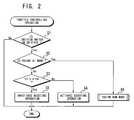
- the CPU 31 determines whether or not the ignition switch 20 of the vehicle is turned on (step S1). If the ignition switch 20 is turned off, the CPU 31 ends the throttle valve controlling operation soon. If the ignition switch 20 is turned on, the CPU 31 determines whether or not the internal combustion engine is at work (step S2).
- a rotational speed sensor for detecting a rotational speed of the internal combustion engine is not shown in Fig. 1. However, when the rotational speed detected by the rotational speed sensor is higher than or equal to a predetermined speed (for example, 500 rpm), it can be determined that the internal combustion engine is at work.
- the CPU 31 determines whether or not the output voltage Vr of the boosting circuit 18 is higher than or equal to a threshold voltage Vthr (step S3).
- the threshold voltage Vthr is a voltage higher than the output voltage Vb of the power source 17. If Vr#Vthr, the CPU 31 supplies a boost switching signal to the transistor 42 of the boosting circuit 18 to activate the boosting circuit 18 (step S4). If Vr>Vthr, which indicates that the output voltage Vr of the boosting circuit 18 is sufficiently high, the CPU 31 stops the supply of the boost switching signal to inactivate the boosting circuit 18 (step S5).
- the boost switching signal is supplied to the base of the transistor 42, so that the transistor 42 repeats on/off in accordance with the boost switching signal.
- the output voltage Vr of the boosting circuit 18 is equal to the output voltage Vb of the power source 17 immediately after that the ignition switch 20 has been turned on, and gradually increases with a lapse of time due to the boosting operation by the repeated on/off of the transistor 42.
- the output voltage Vr of the boosting circuit 18 is higher than the threshold voltage Vthr, the supply of the boost switching signal to the base of the transistor 42 is stopped, so that the boosting circuit 18 stops the boosting operation.
- an engine run mode is started in the CPU 31 (step S6).
- the CPU 31 reads an accelerator opening degree detected by the accelerator opening degree sensor 14 (step S11), and sets a target throttle valve opening degree THr corresponding to the accelerator opening degree detected (step S12).
- the target throttle valve opening degree THr at step S12 is set by reading data of THr corresponding to the detected accelerator opening degree using a data table for setting THr which is previously formed in the ROM 32, for example.
- the driving current value Cm at step S15 is set by reading data of Cm corresponding to the calculated opening degree difference ⁇ TH using a data table for setting Cm which is previously formed in the ROM 32, for example. The larger the opening degree difference ⁇ TH becomes, the higher the driving current value Cm is set.
- the CPU 31 determines whether or not the magnitude
- the switching determination current value is previously set. If
- the CPU 31 sets a duty ratio DR corresponding to the driving current value Cm (step S18), after executing step S17.
- the duty ratio DR indicates a period for which the driving current value Cm can be obtain averagely in the duty cycle by applying the output voltage Vr of the boosting circuit 18 to the motor 11.
- the duty ratio DR can be also set using a duty ratio setting data table for Vr which is previously formed in the ROM 32, for example.
- step S16 If a result of the determination at step S16 indicates
- the switching element 51 turns off and the switching element 52 turns on in response to the normal voltage supply instruction.
- the output voltage Vb of the power source 17 is supplied to the driver 12 through the switching element 52.
- the CPU 31 determines whether or not the output voltage Vr of the boosting circuit 18 is higher than the threshold voltage Vthr (step S20), after executing the step S19. If Vr#Vthr, the CPU 31 supplies a boost switching signal to the transistor 42 of the boosting circuit 18 to activate the boosting circuit 18 (step S21). On the other hand, If Vr>Vthr, which means that the output voltage of the boosting circuit 18 is adequately high, the CPU 31 stops the supply of the boost switching signal to inactivate the boosting circuit 18 (step S22). The steps S20 to S22 are equal to the above steps S2 to S4.
- the CPU 31 sets a duty ratio DR corresponding to the driving current value Cm (step S23), after executing step S21 or S22.
- the duty ratio DR at step S23 indicates a period for which the driving current value Cm can be obtain averagely in the duty cycle by applying the output voltage Vb of the power source 17 to the motor 11.
- the duty ratio DR can be also set using a duty ratio setting data table for Vb which is previously formed in the ROM 32, for example.
- step S28 the CPU 31 instructs an off state for the transistors 21 and 24, and an on state for the transistors 22 and 23 to rotate the motor 11 in the reverse direction (step S28).
- the output interface circuit 37 allows the transistors 21 to 24 to turn on or off in response to the on instruction or off instruction for the transistors 21 to 24 from the CPU 31.
- a driving current from the power supply circuit 16 flows into the ground through the transistor 21, the DC motor 11, and transistor 24 in that order.
- the motor 11 rotates in the normal direction to move the throttle valve 12 in the opening direction.
- the driving current from the power supply circuit 16 flows into the ground through the transistor 23, the DC motor 11, and transistor 22 in that order.
- the motor 11 rotates in the reverse direction to move the throttle valve 12 in the closing direction.
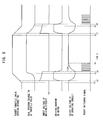
- Fig. 5 shows an operation example of each portion in the throttle valve controlling apparatus when the target throttle valve opening degree THr quickly changes in the opening direction, and after that, quickly changes in the closing direction.
- the target throttle valve opening degree THr starts changing in the opening direction at a time t1, and since
- the driving voltage of the motor 11 is equal to the output voltage Vr of the boosting circuit 18, and the driving current of the motor 11 becomes a current corresponding to the duty ratio DR set at step S18.
- the motor 11 rotates in the normal direction to move the throttle valve 12 in the opening direction.
- the apparatus Since the driving current flows into the motor 11, the output voltage Vr of the boosting circuit 18 decreases gradually.
- the motor 11 rotates in the reverse direction at a time t3. Since
- the driving voltage of the motor 11 In the normal driving state of the motor 11, the driving voltage of the motor 11 is equal to the output voltage Vb of the power source 17, and the driving current of the motor 11 becomes a current corresponding to the duty ratio DR set at step S23.
- the output voltage Vr of the boosting circuit 18 is lower than the threshold voltage Vthr, as shown in Fig. 5, as a result of the boosted driving of the motor 11, a boost switching signal is supplied to the base of the transistor 42.
- the transistor 42 repeats on/off in accordance with the boost switching signal.
- the output voltage Vr of the boosting circuit 18 gradually increases with a lapse of time.
- the output voltage Vr of the boosting circuit 18 is higher than the threshold voltage Vthr at a time t5
- the supply of the boost switching signal to the base of the transistor 42 is stopped, so that the boosting circuit 18 stops the boosting operation.
- the target throttle valve opening degree THr starts changing in the closing direction at a time t6, and since
- the rotational direction of motor 11 is reversed at a time t8. Since
- the output voltage Vr of the boosting circuit 18 gradually increases with a lapse of time.
- the opening degree difference ⁇ TH between the target throttle valve opening degree THr and the real opening degree TH is calculated, the driving current Cm of the motor 11 is set in accordance with the opening degree difference ⁇ TH, and then it is determined whether or not the magnitude
- one of the boosted driving state and the normal driving state can be selected by determining whether or not the magnitude
- the duty ratio DR is set in accordance with the driving current value Cm of the motor 11 in the above embodiment, the duty ratio DR can be set in accordance with the opening degree difference ⁇ TH.
- the structure of the boosting circuit 18 is not limited to that of the above embodiment.
- the target throttle valve opening degree THr is set in accordance with the stepping-in amount of the accelerator pedal in the above embodiment, the target throttle valve opening degree THr can be set in accordance with another engine parameter such as an engine rotational speed without limiting to the stepping-in amount.
- one voltage of the output voltage of the boosting means and the output voltage of a DC power source is selectively applied to the DC motor in accordance with the difference between the real opening degree and the target opening degree of the throttle valve. Therefore, since the DC motor of small size can be used, the apparatus can be downsized and dropped in cost. By using the small DC motor, the apparatus can have flexibility in mounting into a vehicle. Further, since the output voltage of the boosting means can be applied to the DC motor at a transition state of the internal combustion engine, it is possible to sufficiently obtain torque for quickly opening or closing the throttle valve.
Landscapes
- Engineering & Computer Science (AREA)
- Chemical & Material Sciences (AREA)
- Combustion & Propulsion (AREA)
- Mechanical Engineering (AREA)
- General Engineering & Computer Science (AREA)
- Electrical Control Of Air Or Fuel Supplied To Internal-Combustion Engine (AREA)
- Control Of Throttle Valves Provided In The Intake System Or In The Exhaust System (AREA)
Abstract
Description
- The present invention relates to a throttle valve controlling apparatus of a motor drive type for opening/closing-driving a throttle valve of an internal combustion engine through a DC (direct current) motor.
- In a conventional throttle valve controlling apparatus of a motor drive type, an accelerator opening degree sensor for detecting a stepping-in amount (accelerator opening degree) of an accelerator pedal, a throttle valve opening degree sensor for detecting a real opening degree of a throttle valve, a DC motor for driving the throttle valve, and a controlling circuit for controlling rotation of the motor are provided (see, for example, Japanese Patent Application Kokai No. 2000-156989). The conventional apparatus sets a target throttle valve opening degree corresponding to the accelerator opening degree detected by the accelerator opening degree sensor, sets a duty ratio based on the difference between the target throttle valve opening degree and the real throttle valve opening degree detected by the throttle valve opening degree sensor, and drives the motor at the set duty ratio. The motor is supplied with a current corresponding to the duty ratio, so that the throttle valve is driven to decrease the difference between the target throttle valve opening degree and the real throttle valve opening degree.
- In the conventional throttle valve controlling apparatus, as the DC motor, one which is capable to sufficiently obtain torque required to open or close the throttle valve in a transition operation state such as hard acceleration and hard deceleration of the internal combustion engine is usually used. However, since a DC motor which can satisfy such a condition becomes relatively large, there is a problem that it is difficult to downsize the throttle valve controlling apparatus.
- Then, an object of the present invention is to provide a throttle valve controlling apparatus which can downsize itself and properly open or close a throttle valve even when the internal combustion engine is in a transition operation state.
- According to the invention, there is provided an apparatus for controlling an opening degree of a throttle valve of an internal combustion engine by giving rotary power of a DC motor to the throttle valve, comprising: detecting means for detecting a real opening degree of the throttle valve; target opening degree setting means for setting a target opening degree of the throttle valve in accordance with an operation state of the internal combustion engine; boosting means for boosting an output voltage of a DC power source; and drive controlling means for selecting one voltage of an output voltage of the boosting means and the output voltage of the DC power source in accordance with an opening degree difference between the real opening degree and the target opening degree, and applying the selected one voltage to the DC motor.
-
- Fig. 1 is a block diagram showing an embodiment of the present invention;
- Fig. 2 is a flowchart showing a throttle valve controlling operation;
- Fig. 3 is a diagram showing operation of each portion of an apparatus in a period immediately after that an ignition switch is turned on;
- Fig. 4 is a flowchart showing an engine run mode operation; and
- Fig. 5 is a diagram showing operation of each portion of the apparatus in an engine run mode.
- An embodiment of the present invention will be hereinafter explained in detail with reference to the accompanying drawings.
- Fig. 1 shows a throttle valve controlling apparatus of a motor drive type according to the present invention. The throttle valve controlling apparatus is an apparatus for controlling the opening degree of a
throttle valve 2 in anintake pipe 1 of an internal combustion engine mounted in a vehicle, and comprises aDC motor 11, adriver 12, acontroller 13, an acceleratoropening degree sensor 14, a throttlevalve degree sensor 15, and apower supply circuit 16. - The
DC motor 11 drives thethrottle valve 2 to change the opening degree, and the drive of thethrottle valve 2 is controlled by thecontroller 13 through thedriver 12. - The
driver 12 includes fourtransistors 21 to 24, anddiodes transistors transistors transistors DC motor 11, the collectors of thetransistors DC motor 11. The emitters of thetransistors driver 12, are connected to the output of thepower supply circuit 16. The emitters of thetransistors transistors 21 to 24 are connected to thecontroller 13. Thediode 25 is connected between the emitter and the collector of thetransistor 21, and thediode 26 is connected between the emitter and the collector of thetransistor 23. - The
controller 13 includes a CPU (central processing unit) 31, a ROM (read only memory) 32, a RAM (random access memory) 33, an A/D (analog/digital)convertor 34, anoutput port circuit 35, aninput interface circuit 36, and anoutput interface circuit 37. TheCPU 31, theROM 32, theRAM 33, the A/D convertor 34, and theoutput port circuit 35 are connected in common by a bus. TheCPU 31 executes a throttle valve controlling operation to control the opening degree of thethrottle valve 2. The A/D convertor 34 is connected to theinput interface circuit 36. Theoutput port circuit 35 is connected to theoutput interface circuit 37. - The accelerator
opening degree sensor 14 detects a stepping-in amount (accelerator opening degree) of an accelerator pedal of the vehicle to generate a voltage signal based on the accelerator opening degree. - The throttle
valve degree sensor 15 detects a real opening degree of thethrottle valve 12 to generate a voltage signal based on the real opening degree. - The
power supply circuit 16 has aboosting circuit 18 and aswitching circuit 19. Theboosting circuit 18 is a circuit for boosting an output voltage Vb (for example, 12 V) of aDC power source 17, and has acoil 41, aswitching transistor 42, adiode 43, and acapacitor 44. - The
power source 17 is a battery for outputting the voltage Vb which is an approximate constant voltage. The positive terminal of thepower source 17 is connected to thepower supply circuit 16 through anignition switch 20, and the negative terminal is grounded. - One end of the
coil 41 is connected to the positive terminal of thepower source 17 and functions as an input of theboosting circuit 18, and the other end of thecoil 41 is connected to the anode of thediode 43. The cathode of thediode 43 is grounded through thecapacitor 44 and functions as an output of theboosting circuit 18. The connecting line between thecoil 41 and the anode of thediode 43 is connected to the collector of thetransistor 42. The emitter of thetransistor 42 is grounded. The base of thetransistor 42 is connected to theoutput interface circuit 37. Thecoil 42 generates a boosted voltage Vr when thetransistor 42 repeats turning-on/off. The boosted voltage Vr is applied to thecapacitor 44 to charge thecapacitor 44. - The
switching circuit 19 selectively supplies one of the output voltage Vb of thepower source 17 and the boosted voltage Vr of theboosting circuit 18 to thedriver 12 in accordance with control by thecontroller 13. Theswitching circuit 19 has twoswitching elements switching element 51 is connected to the output of theboosting circuit 18, and one end of theswitching element 52 is connected to the positive terminal of thepower source 17. The other ends of theswitching elements driver 12. Each of theswitching elements output interface circuit 37, so as to turn on/off in response to an instruction from theCPU 31. - In the
power supply circuit 16, thediode 53 is arranged between the input and the output of theboosting circuit 18. Thediode 53 is applied the output voltage Vb of thepower source 17 to thecapacitor 44 in theboosting circuit 18 when theignition switch 20 is turned on. - The
input interface circuit 36 of thecontroller 13 is supplied with the output voltage Vr, the output signal of the acceleratoropening degree sensor 14, and the output signal of the throttlevalve degree sensor 15. Each of these voltage and signals supplied to theinput interface circuit 36 is selectively converted into a digital signal by the A/D convertor 34. The digital signal is supplied to theCPU 31, so that theCPU 31 can read the output voltage Vr of theboosting circuit 18, the accelerator opening degree, and the real opening degree of thethrottle valve 2. - The
CPU 31 controls on/off of thetransistor 42 of theboosting circuit 18, on/off of each of the switching elements of theswitching circuit 19, and on/off of each of thetransistors 21 to 24 of thedriver 12 by executing the above throttle valve controlling operation. A control instruction for each of the on/off operations is supplied to the transistor or element from theCPU 31 through theoutput port circuit 35 and theoutput interface circuit 37. By controlling at a duty ratio the on/off operations of thetransistors 21 to 24 in thedriver 12, a current supplied to themotor 11 is controlled, so that the opening degree of thethrottle valve 2 is controlled. - In the throttle valve controlling apparatus with the above structure, the
CPU 31 repeatedly executes the throttle valve controlling operation for each predetermined period Tc. The predetermined period Tc is equal to a duty cycle in the duty ratio control. - In the throttle valve controlling operation, as shown in Fig. 2, the
CPU 31 determines whether or not theignition switch 20 of the vehicle is turned on (step S1). If theignition switch 20 is turned off, theCPU 31 ends the throttle valve controlling operation soon. If theignition switch 20 is turned on, theCPU 31 determines whether or not the internal combustion engine is at work (step S2). A rotational speed sensor for detecting a rotational speed of the internal combustion engine is not shown in Fig. 1. However, when the rotational speed detected by the rotational speed sensor is higher than or equal to a predetermined speed (for example, 500 rpm), it can be determined that the internal combustion engine is at work. - When the internal combustion engine is not at work, the
CPU 31 determines whether or not the output voltage Vr of the boostingcircuit 18 is higher than or equal to a threshold voltage Vthr (step S3). The threshold voltage Vthr is a voltage higher than the output voltage Vb of thepower source 17. If Vr#Vthr, theCPU 31 supplies a boost switching signal to thetransistor 42 of the boostingcircuit 18 to activate the boosting circuit 18 (step S4). If Vr>Vthr, which indicates that the output voltage Vr of the boostingcircuit 18 is sufficiently high, theCPU 31 stops the supply of the boost switching signal to inactivate the boosting circuit 18 (step S5). - As shown in Fig. 3, when the
ignition switch 20 is turned on, the boost switching signal is supplied to the base of thetransistor 42, so that thetransistor 42 repeats on/off in accordance with the boost switching signal. Thus, the output voltage Vr of the boostingcircuit 18 is equal to the output voltage Vb of thepower source 17 immediately after that theignition switch 20 has been turned on, and gradually increases with a lapse of time due to the boosting operation by the repeated on/off of thetransistor 42. When the output voltage Vr of the boostingcircuit 18 is higher than the threshold voltage Vthr, the supply of the boost switching signal to the base of thetransistor 42 is stopped, so that the boostingcircuit 18 stops the boosting operation. - If a result of the determination at step S2 indicates that the internal combustion engine is at work, an engine run mode is started in the CPU 31 (step S6). In the engine run mode, as shown in Fig. 4, the
CPU 31 reads an accelerator opening degree detected by the accelerator opening degree sensor 14 (step S11), and sets a target throttle valve opening degree THr corresponding to the accelerator opening degree detected (step S12). The target throttle valve opening degree THr at step S12 is set by reading data of THr corresponding to the detected accelerator opening degree using a data table for setting THr which is previously formed in theROM 32, for example. TheCPU 31 reads a real opening degree TH of thethrottle valve 12 detected by the throttle valve degree sensor 15 (step S13), and calculates an opening degree difference ΔTH = THr - TH between the target throttle valve opening degree THr and the real opening degree TH (step S14). Further, theCPU 31 sets a driving current value Cm for themotor 11 based on the opening degree difference ΔTH (step S15). The driving current value Cm at step S15 is set by reading data of Cm corresponding to the calculated opening degree difference ΔTH using a data table for setting Cm which is previously formed in theROM 32, for example. The larger the opening degree difference ΔTH becomes, the higher the driving current value Cm is set. - The
CPU 31 determines whether or not the magnitude |Cm| of the driving current value Cm set at step S15 is larger than a switching determination current value (predetermined threshold) Csdr (step S16). The switching determination current value is previously set. If |Cm|>Csdr, which means the time themotor 11 is driven by a boosted voltage, theCPU 31 generates a boosted voltage supply instruction for the switching circuit 19 (step S17). In the switchingcircuit 19, the switchingelement 51 turns on and the switchingelement 52 turns off in response to the boosted voltage supply instruction. Thus, the output voltage Vr is supplied to thedriver 12 through the switchingelement 51. - The
CPU 31 sets a duty ratio DR corresponding to the driving current value Cm (step S18), after executing step S17. The duty ratio DR indicates a period for which the driving current value Cm can be obtain averagely in the duty cycle by applying the output voltage Vr of the boostingcircuit 18 to themotor 11. The duty ratio DR can be also set using a duty ratio setting data table for Vr which is previously formed in theROM 32, for example. - If a result of the determination at step S16 indicates |Cm|#Csdr, which means the time the
motor 11 is driven by a normal voltage, theCPU 31 generates a normal voltage supply instruction for the switching circuit 19 (step S19). In the switchingcircuit 19, the switchingelement 51 turns off and the switchingelement 52 turns on in response to the normal voltage supply instruction. Thus, the output voltage Vb of thepower source 17 is supplied to thedriver 12 through the switchingelement 52. - The
CPU 31 determines whether or not the output voltage Vr of the boostingcircuit 18 is higher than the threshold voltage Vthr (step S20), after executing the step S19. If Vr#Vthr, theCPU 31 supplies a boost switching signal to thetransistor 42 of the boostingcircuit 18 to activate the boosting circuit 18 (step S21). On the other hand, If Vr>Vthr, which means that the output voltage of the boostingcircuit 18 is adequately high, theCPU 31 stops the supply of the boost switching signal to inactivate the boosting circuit 18 (step S22). The steps S20 to S22 are equal to the above steps S2 to S4. - The
CPU 31 sets a duty ratio DR corresponding to the driving current value Cm (step S23), after executing step S21 or S22. The duty ratio DR at step S23 indicates a period for which the driving current value Cm can be obtain averagely in the duty cycle by applying the output voltage Vb of thepower source 17 to themotor 11. The duty ratio DR can be also set using a duty ratio setting data table for Vb which is previously formed in theROM 32, for example. - The
CPU 31 judges the rotational direction of themotor 11 in accordance with the polarity of the opening degree difference ΔTH (step S24). If the opening degree difference ΔTH is positive, theCPU 31 instructs an on state for thetransistors transistors motor 11 in the normal direction (step S25). After that, theCPU 31 determines whether or not a period TDR = Tc H DR corresponding to the duty ratio DR has been passed by (step S26). Tc indicates the above duty cycle. If the period TDR has been passed by, theCPU 31 instructs an off state for thetransistors 21 to 24 (step S27). On the other hand, If the opening degree difference ΔTH is negative, theCPU 31 instructs an off state for thetransistors transistors motor 11 in the reverse direction (step S28). After executing step S28, theCPU 31 determines whether or not the period TDR = Tc H DR corresponding to the duty ratio DR has been passed by at step S26. If the period TDR has been passed by, theCPU 31 instructs the off state for thetransistors 21 to 24 at step S27. - The
output interface circuit 37 allows thetransistors 21 to 24 to turn on or off in response to the on instruction or off instruction for thetransistors 21 to 24 from theCPU 31. In response to the on/off instructions of step S25, when thetransistors transistors power supply circuit 16 flows into the ground through thetransistor 21, theDC motor 11, andtransistor 24 in that order. Thus, themotor 11 rotates in the normal direction to move thethrottle valve 12 in the opening direction. On the other hand, in response to the on/off instructions of step S28, when thetransistors transistors power supply circuit 16 flows into the ground through thetransistor 23, theDC motor 11, andtransistor 22 in that order. Thus, themotor 11 rotates in the reverse direction to move thethrottle valve 12 in the closing direction. - For example, when the internal combustion engine operates under hard acceleration or hard deceleration, |Cm|>Csdr is satisfied, and
motor 11 becomes a boosted driving state. In the boosted driving state, the switchingelement 51 of the switchingcircuit 19 turns on and the switchingelement 52 of the switchingcircuit 19 turns off in thepower supply circuit 16, so that a driving current based on the output voltage Vr of the boostingcircuit 18 is supplied to themotor 11 through the switchingelement 51. - When the internal combustion engine is under a steady operation state, |Cm|#Csdr is satisfied, and
motor 11 becomes a normal driving state. In the normal driving state, the switchingelement 51 of the switchingcircuit 19 turns off and the switchingelement 52 of the switchingcircuit 19 turns on in thepower supply circuit 16, so that a driving current based on the output voltage Vb of thepower source 17 is supplied to themotor 11 through the switchingelement 52. - Fig. 5 shows an operation example of each portion in the throttle valve controlling apparatus when the target throttle valve opening degree THr quickly changes in the opening direction, and after that, quickly changes in the closing direction. The target throttle valve opening degree THr starts changing in the opening direction at a time t1, and since |Cm|>Csdr is determined at a time t2, the apparatus changes into the boosted driving state of the
motor 11. In the boosted driving state of themotor 11, the driving voltage of themotor 11 is equal to the output voltage Vr of the boostingcircuit 18, and the driving current of themotor 11 becomes a current corresponding to the duty ratio DR set at step S18. Thus, themotor 11 rotates in the normal direction to move thethrottle valve 12 in the opening direction. Since the driving current flows into themotor 11, the output voltage Vr of the boostingcircuit 18 decreases gradually. Themotor 11 rotates in the reverse direction at a time t3. Since |Cm|#Csdr is determined at a time t4, the apparatus changes into the normal driving state of themotor 11. In the normal driving state of themotor 11, the driving voltage of themotor 11 is equal to the output voltage Vb of thepower source 17, and the driving current of themotor 11 becomes a current corresponding to the duty ratio DR set at step S23. At that time, if the output voltage Vr of the boostingcircuit 18 is lower than the threshold voltage Vthr, as shown in Fig. 5, as a result of the boosted driving of themotor 11, a boost switching signal is supplied to the base of thetransistor 42. Thetransistor 42 repeats on/off in accordance with the boost switching signal. Thus, the output voltage Vr of the boostingcircuit 18 gradually increases with a lapse of time. When the output voltage Vr of the boostingcircuit 18 is higher than the threshold voltage Vthr at a time t5, the supply of the boost switching signal to the base of thetransistor 42 is stopped, so that the boostingcircuit 18 stops the boosting operation. - Similarly, the target throttle valve opening degree THr starts changing in the closing direction at a time t6, and since |Cm|>Csdr is determined at a time t7, the apparatus changes into the boosted driving state of the
motor 11. The rotational direction ofmotor 11 is reversed at a time t8. Since |Cm|#Csdr is determined at a time t9, the apparatus changes into the normal driving state of themotor 11. At that time, thetransistor 42 repeats on/off in accordance with the boost switching signal. Thus, the output voltage Vr of the boostingcircuit 18 gradually increases with a lapse of time. - In the above embodiment, the opening degree difference ΔTH between the target throttle valve opening degree THr and the real opening degree TH is calculated, the driving current Cm of the
motor 11 is set in accordance with the opening degree difference ΔTH, and then it is determined whether or not the magnitude |Cm| of the driving current value Cm is larger than the switching determination current value Csdr. However, one of the boosted driving state and the normal driving state can be selected by determining whether or not the magnitude |ΔTH| of the opening degree difference ΔTH is larger than a switching determination value THsdr. Although the duty ratio DR is set in accordance with the driving current value Cm of themotor 11 in the above embodiment, the duty ratio DR can be set in accordance with the opening degree difference ΔTH. Further, the structure of the boostingcircuit 18 is not limited to that of the above embodiment. - Although the target throttle valve opening degree THr is set in accordance with the stepping-in amount of the accelerator pedal in the above embodiment, the target throttle valve opening degree THr can be set in accordance with another engine parameter such as an engine rotational speed without limiting to the stepping-in amount.
- As described above, according to the present invention, one voltage of the output voltage of the boosting means and the output voltage of a DC power source is selectively applied to the DC motor in accordance with the difference between the real opening degree and the target opening degree of the throttle valve. Therefore, since the DC motor of small size can be used, the apparatus can be downsized and dropped in cost. By using the small DC motor, the apparatus can have flexibility in mounting into a vehicle. Further, since the output voltage of the boosting means can be applied to the DC motor at a transition state of the internal combustion engine, it is possible to sufficiently obtain torque for quickly opening or closing the throttle valve.
Claims (6)
- An apparatus for controlling an opening degree of a throttle valve of an internal combustion engine by giving rotary power of a DC (direct current) motor to said throttle valve, comprising:detecting means for detecting a real opening degree of said throttle valve;target opening degree setting means for setting a target opening degree of said throttle valve in accordance with an operation state of said internal combustion engine;boosting means for boosting an output voltage of a DC power source; anddrive controlling means for selecting one voltage of an output voltage of said boosting means and the output voltage of said DC power source in accordance with an opening degree difference between the real opening degree and the target opening degree, and applying the selected one voltage to said DC motor.
- An apparatus according to claim 1, wherein said drive controlling means includes:driving current setting means for setting a driving current value of said DC motor corresponding to the opening degree difference;determining means for determining whether or not the magnitude of the driving current value is higher than a predetermined threshold;switching means for outputting the output voltage of said boosting means when said determining means determines that the magnitude of the driving current value is higher than the predetermined threshold, and outputting the output voltage of said DC power source when said determining means determines that the magnitude of the driving current value is lower than or equal to the predetermined threshold; anddriving means for applying the output voltage of said switching means to said DC motor in a polarity direction based on whether or not the opening degree difference is positive.
- An apparatus according to claim 1, wherein said boosting means includes a capacitor, and boosted voltage generating means for boosting the output voltage of said DC power source and applying the boosted voltage to said capacitor, and outputs a voltage between both ends of said capacitor.
- An apparatus according to claim 3, wherein said boosting means includes boost controlling means for activating said boosted voltage generating means when the voltage between the both ends of said capacitor is lower than or equal to a threshold voltage at a case of selecting the output voltage of said DC power source.
- An apparatus according to claim 2, wherein said driving means for applying the output voltage of said switching means to said DC motor at a duty ratio corresponding to the driving current value for each predetermined period.
- An apparatus according to claim 1, wherein said target opening degree setting means sets the target opening degree of said throttle valve in accordance with a stepping-in amount of an accelerator pedal as the operation state of said internal combustion engine.
Applications Claiming Priority (1)
| Application Number | Priority Date | Filing Date | Title |
|---|---|---|---|
| JP2004192988A JP2006016979A (en) | 2004-06-30 | 2004-06-30 | Throttle valve control device for internal combustion engine |
Publications (2)
| Publication Number | Publication Date |
|---|---|
| EP1612388A2 true EP1612388A2 (en) | 2006-01-04 |
| EP1612388A3 EP1612388A3 (en) | 2008-03-19 |
Family
ID=34982328
Family Applications (1)
| Application Number | Title | Priority Date | Filing Date |
|---|---|---|---|
| EP05105565A Withdrawn EP1612388A3 (en) | 2004-06-30 | 2005-06-22 | Apparatus For Controlling Throttle Valve Of Internal Combustion Engine |
Country Status (3)
| Country | Link |
|---|---|
| US (1) | US7086380B2 (en) |
| EP (1) | EP1612388A3 (en) |
| JP (1) | JP2006016979A (en) |
Families Citing this family (1)
| Publication number | Priority date | Publication date | Assignee | Title |
|---|---|---|---|---|
| WO2011133787A1 (en) * | 2010-04-21 | 2011-10-27 | Medtronic Inc. | Prosthetic valve with sealing members and methods of use thereof |
Family Cites Families (7)
| Publication number | Priority date | Publication date | Assignee | Title |
|---|---|---|---|---|
| DE3742969C2 (en) * | 1987-12-18 | 1995-11-16 | Pierburg Gmbh | Device for adjusting a throttle valve of an air intake line of an internal combustion engine |
| US4875448A (en) * | 1988-09-23 | 1989-10-24 | Briggs & Stratton Corporation | Cyclic responding electronic speed governor |
| KR960007409B1 (en) * | 1994-04-01 | 1996-05-31 | 아시아자동차공업주식회사 | Accelerator pedal controller |
| DE19748354B4 (en) * | 1997-11-03 | 2005-06-23 | Robert Bosch Gmbh | Method and device for controlling an actuating element |
| JP3724964B2 (en) | 1998-11-18 | 2005-12-07 | 株式会社デンソー | Motor drive device |
| US6612287B2 (en) * | 2001-10-16 | 2003-09-02 | Visteon Global Technologies, Inc. | Electronic throttle position feedforward system |
| JP2005113767A (en) * | 2003-10-07 | 2005-04-28 | Keihin Corp | Electronic control valve drive |
-
2004
- 2004-06-30 JP JP2004192988A patent/JP2006016979A/en active Pending
-
2005
- 2005-06-22 EP EP05105565A patent/EP1612388A3/en not_active Withdrawn
- 2005-06-28 US US11/167,101 patent/US7086380B2/en not_active Expired - Fee Related
Also Published As
| Publication number | Publication date |
|---|---|
| US20060000444A1 (en) | 2006-01-05 |
| EP1612388A3 (en) | 2008-03-19 |
| JP2006016979A (en) | 2006-01-19 |
| US7086380B2 (en) | 2006-08-08 |
Similar Documents
| Publication | Publication Date | Title |
|---|---|---|
| US5818178A (en) | Valve control apparatus for an automobile | |
| CN1316729C (en) | Single-phase motor driving device, single-phase motor driving method | |
| US6175484B1 (en) | Energy recovery circuit configuration for solenoid injector driver circuits | |
| JP3319150B2 (en) | Control device for fuel pump for internal combustion engine | |
| US5841261A (en) | System for controlling stepping motor for dividing a single step of the motor into plural sections and applying voltages whose levels are determined in accordance with the sections | |
| US5998881A (en) | Apparatus and method for controlling low engine idle RPM without discharging a vehicle battery by monitoring the vehicle alternator field modulation | |
| US5754024A (en) | Control device for switched reluctance motor | |
| JP4316568B2 (en) | Vehicle generator control system | |
| EP1524762A3 (en) | Output control apparatus for synchronous power generator | |
| JPH06168791A (en) | Inverter circuit | |
| US7086380B2 (en) | Apparatus for controlling throttle valve of internal combustion engine | |
| JPH03237241A (en) | Idle rotation controller of engine | |
| JP3801731B2 (en) | Electric motor energization control device | |
| US6639374B2 (en) | Method and device for controlling DC servomotor for driving rotating load | |
| US6122582A (en) | Control device for automatic transmission | |
| EP0223426B1 (en) | Method and apparatus for controlling the solenoid current of a solenoid valve which controls an internal combustion engine | |
| US11041472B2 (en) | Motor driving device | |
| JP2638355B2 (en) | Engine idle speed control method | |
| JPH08182378A (en) | Method and apparatus for detecting rotor position of brushless motor | |
| JPS6119946A (en) | Engine throttle control method | |
| JPH0739200A (en) | Voltage control device for vehicle generator | |
| JPH07123797A (en) | Rotational fluctuation control device | |
| JP3441109B2 (en) | Drive control device for electric vehicle | |
| KR100193418B1 (en) | Engine Throttle Valve Position Control | |
| JP3441092B2 (en) | Startup control method for brushless motor |
Legal Events
| Date | Code | Title | Description |
|---|---|---|---|
| PUAI | Public reference made under article 153(3) epc to a published international application that has entered the european phase |
Free format text: ORIGINAL CODE: 0009012 |
|
| AK | Designated contracting states |
Kind code of ref document: A2 Designated state(s): AT BE BG CH CY CZ DE DK EE ES FI FR GB GR HU IE IS IT LI LT LU MC NL PL PT RO SE SI SK TR |
|
| AX | Request for extension of the european patent |
Extension state: AL BA HR LV MK YU |
|
| PUAL | Search report despatched |
Free format text: ORIGINAL CODE: 0009013 |
|
| AK | Designated contracting states |
Kind code of ref document: A3 Designated state(s): AT BE BG CH CY CZ DE DK EE ES FI FR GB GR HU IE IS IT LI LT LU MC NL PL PT RO SE SI SK TR |
|
| AX | Request for extension of the european patent |
Extension state: AL BA HR LV MK YU |
|
| 17P | Request for examination filed |
Effective date: 20080526 |
|
| GRAP | Despatch of communication of intention to grant a patent |
Free format text: ORIGINAL CODE: EPIDOSNIGR1 |
|
| RIN1 | Information on inventor provided before grant (corrected) |
Inventor name: KOBAYASHI, HIROMICHI Inventor name: MUKASA, TAMIKAZU |
|
| RTI1 | Title (correction) |
Free format text: APPARATUS FOR CONTROLLING THROTTLE VALVE OF INTERNAL COMBUSTION ENGINE |
|
| AKX | Designation fees paid |
Designated state(s): DE FR GB |
|
| STAA | Information on the status of an ep patent application or granted ep patent |
Free format text: STATUS: THE APPLICATION IS DEEMED TO BE WITHDRAWN |
|
| 18D | Application deemed to be withdrawn |
Effective date: 20090207 |