EP1612067B1 - Vehicle state analyzing system, vehicle, and vehicle state managing system - Google Patents
Vehicle state analyzing system, vehicle, and vehicle state managing system Download PDFInfo
- Publication number
- EP1612067B1 EP1612067B1 EP04725170A EP04725170A EP1612067B1 EP 1612067 B1 EP1612067 B1 EP 1612067B1 EP 04725170 A EP04725170 A EP 04725170A EP 04725170 A EP04725170 A EP 04725170A EP 1612067 B1 EP1612067 B1 EP 1612067B1
- Authority
- EP
- European Patent Office
- Prior art keywords
- vehicle
- state
- analyzing
- force
- fluctuation
- Prior art date
- Legal status (The legal status is an assumption and is not a legal conclusion. Google has not performed a legal analysis and makes no representation as to the accuracy of the status listed.)
- Expired - Lifetime
Links
- 230000008859 change Effects 0.000 claims description 48
- 239000000725 suspension Substances 0.000 claims description 48
- 238000000034 method Methods 0.000 claims description 12
- 238000012360 testing method Methods 0.000 claims description 7
- 238000003860 storage Methods 0.000 abstract description 9
- 230000005484 gravity Effects 0.000 description 7
- 230000008439 repair process Effects 0.000 description 7
- 230000036962 time dependent Effects 0.000 description 7
- 230000000694 effects Effects 0.000 description 5
- 230000006399 behavior Effects 0.000 description 4
- 238000002474 experimental method Methods 0.000 description 4
- 238000012544 monitoring process Methods 0.000 description 4
- 230000002159 abnormal effect Effects 0.000 description 2
- 230000001133 acceleration Effects 0.000 description 2
- 230000005540 biological transmission Effects 0.000 description 2
- 238000004891 communication Methods 0.000 description 2
- 230000003247 decreasing effect Effects 0.000 description 2
- 238000006073 displacement reaction Methods 0.000 description 2
- 238000009826 distribution Methods 0.000 description 2
- 238000011156 evaluation Methods 0.000 description 2
- 230000006870 function Effects 0.000 description 2
- 238000012545 processing Methods 0.000 description 2
- 230000000087 stabilizing effect Effects 0.000 description 2
- 238000010276 construction Methods 0.000 description 1
- 238000001514 detection method Methods 0.000 description 1
- 239000006185 dispersion Substances 0.000 description 1
- 238000012423 maintenance Methods 0.000 description 1
- 230000007246 mechanism Effects 0.000 description 1
- 230000002265 prevention Effects 0.000 description 1
- 230000009467 reduction Effects 0.000 description 1
- 238000005096 rolling process Methods 0.000 description 1
- 238000000926 separation method Methods 0.000 description 1
- 230000008054 signal transmission Effects 0.000 description 1
- 238000009987 spinning Methods 0.000 description 1
Images



Classifications
-
- B—PERFORMING OPERATIONS; TRANSPORTING
- B60—VEHICLES IN GENERAL
- B60G—VEHICLE SUSPENSION ARRANGEMENTS
- B60G17/00—Resilient suspensions having means for adjusting the spring or vibration-damper characteristics, for regulating the distance between a supporting surface and a sprung part of vehicle or for locking suspension during use to meet varying vehicular or surface conditions, e.g. due to speed or load
- B60G17/015—Resilient suspensions having means for adjusting the spring or vibration-damper characteristics, for regulating the distance between a supporting surface and a sprung part of vehicle or for locking suspension during use to meet varying vehicular or surface conditions, e.g. due to speed or load the regulating means comprising electric or electronic elements
- B60G17/019—Resilient suspensions having means for adjusting the spring or vibration-damper characteristics, for regulating the distance between a supporting surface and a sprung part of vehicle or for locking suspension during use to meet varying vehicular or surface conditions, e.g. due to speed or load the regulating means comprising electric or electronic elements characterised by the type of sensor or the arrangement thereof
-
- B—PERFORMING OPERATIONS; TRANSPORTING
- B60—VEHICLES IN GENERAL
- B60G—VEHICLE SUSPENSION ARRANGEMENTS
- B60G17/00—Resilient suspensions having means for adjusting the spring or vibration-damper characteristics, for regulating the distance between a supporting surface and a sprung part of vehicle or for locking suspension during use to meet varying vehicular or surface conditions, e.g. due to speed or load
- B60G17/015—Resilient suspensions having means for adjusting the spring or vibration-damper characteristics, for regulating the distance between a supporting surface and a sprung part of vehicle or for locking suspension during use to meet varying vehicular or surface conditions, e.g. due to speed or load the regulating means comprising electric or electronic elements
- B60G17/016—Resilient suspensions having means for adjusting the spring or vibration-damper characteristics, for regulating the distance between a supporting surface and a sprung part of vehicle or for locking suspension during use to meet varying vehicular or surface conditions, e.g. due to speed or load the regulating means comprising electric or electronic elements characterised by their responsiveness, when the vehicle is travelling, to specific motion, a specific condition, or driver input
-
- B—PERFORMING OPERATIONS; TRANSPORTING
- B60—VEHICLES IN GENERAL
- B60G—VEHICLE SUSPENSION ARRANGEMENTS
- B60G17/00—Resilient suspensions having means for adjusting the spring or vibration-damper characteristics, for regulating the distance between a supporting surface and a sprung part of vehicle or for locking suspension during use to meet varying vehicular or surface conditions, e.g. due to speed or load
- B60G17/015—Resilient suspensions having means for adjusting the spring or vibration-damper characteristics, for regulating the distance between a supporting surface and a sprung part of vehicle or for locking suspension during use to meet varying vehicular or surface conditions, e.g. due to speed or load the regulating means comprising electric or electronic elements
- B60G17/018—Resilient suspensions having means for adjusting the spring or vibration-damper characteristics, for regulating the distance between a supporting surface and a sprung part of vehicle or for locking suspension during use to meet varying vehicular or surface conditions, e.g. due to speed or load the regulating means comprising electric or electronic elements characterised by the use of a specific signal treatment or control method
-
- B—PERFORMING OPERATIONS; TRANSPORTING
- B60—VEHICLES IN GENERAL
- B60G—VEHICLE SUSPENSION ARRANGEMENTS
- B60G2200/00—Indexing codes relating to suspension types
- B60G2200/40—Indexing codes relating to the wheels in the suspensions
- B60G2200/46—Indexing codes relating to the wheels in the suspensions camber angle
-
- B—PERFORMING OPERATIONS; TRANSPORTING
- B60—VEHICLES IN GENERAL
- B60G—VEHICLE SUSPENSION ARRANGEMENTS
- B60G2200/00—Indexing codes relating to suspension types
- B60G2200/40—Indexing codes relating to the wheels in the suspensions
- B60G2200/462—Toe-in/out
-
- B—PERFORMING OPERATIONS; TRANSPORTING
- B60—VEHICLES IN GENERAL
- B60G—VEHICLE SUSPENSION ARRANGEMENTS
- B60G2400/00—Indexing codes relating to detected, measured or calculated conditions or factors
- B60G2400/50—Pressure
- B60G2400/52—Pressure in tyre
Definitions
- the present invention relates to a vehicle state analyzing system for analyzing the state of a vehicle, a vehicle provided with a vehicle state analyzing system, and a vehicle state management system for managing the state of a vehicle.
- Modem vehicles are provided with various apparatuses for detecting the state thereof.
- the direct type device which directly measures the internal pressure for issuing an alarm
- the indirect type device which detects a change in tire revolution speed resulting from a change in rolling radius due to a change in tire internal pressure for issuing an alarm
- the former uses radio wave for signal transmission to or from a revolving wheel, thus the power supply contained in the rotating element presents technical and durability problems, while the latter gives convenience including the device commonness to the ABS (anti-lock braking system), and the like, but any of the devices of this type has functions specified for the internal pressure of the tire, and is not a system which offers information including that about a change in running stability of the vehicle.
- a system which is used in conjunction with the ABS, the TCS (traction control system), or the like is difficult to accommodate a change when the tire is changed or when the characteristics of the suspension/chassis of the vehicle are changed, thus involving difficulties in adding the user's preference, such as a desired change of the tire, to the vehicle.
- TCS a system which detects a change in a vehicle body acceleration to control the drive force distribution, and when the running stability of the vehicle is deteriorated, prevents such a phenomenon from proceeding.
- TCS a system which detects a change in a vehicle body acceleration to control the drive force distribution, and when the running stability of the vehicle is deteriorated, prevents such a phenomenon from proceeding.
- Such a system is for stabilizing the attitude in cornering (for prevention of spinning, and the like), and is not for a technique in which, for the running stability in pseudo straight running within the minute steering angle region, which is frequently utilized in general running, with grasping a phenomenon of the source which causes a yaw to occur from the motion of the respective wheels, tendency thereof is monitored, or an alignment adjustment which causes the problem is related.
- such a system aims at a control which covers a generated fluctuation in yaw and an occurred change in vehicle acceleration, on the presumption that the initial state of the vehicle varies from vehicle to vehicle,
- a system does not reference to the initial state of the running stability of the vehicle for monitoring and maintaining it, and does not find a problem with a change in internal pressure, an alignment change, or the like.
- Any vehicle can be checked for alignment by using an alignment tester, but the alignment tester cannot examine for fluctuation of the alignment of the vehicle in normal actual running.
- a method which measures the magnitude of a lateral force by use of a platform tester, and adjusts the lateral force to be within the specified tolerance (reference range), but the method will not allow examining the fluctuation of the lateral force to the vehicle when the vehicle normal running.
- the purpose of the present invention is to eliminate the drawbacks of the above-mentioned prior art, and to provide a vehicle state analyzing system, a vehicle, and a vehicle state management system which can grasp a problem of the state of a vehicle in normal running, such as the running stability related to the wheel mounting angle which depends on the characteristics of the tire, the time dependent change of the suspension/chassis or the change in adjustment of the suspension, the change in internal pressure of the tire, and the like.
- a vehicle state analyzing method is provided, as stated in claim 1.
- the running stability of a vehicle is determined by balance of fluctuation of force inputted to the suspension/chassis through the tire.
- the running stability can be managed by monitoring and analyzing, with the input from the road surface which is optimal for each vehicle as being a reference value, the disparate from the current situation.
- the vehicle which is set to be an optimum suspension/chassis state is first run for a certain period of time under a predetermined condition, such as the straight running, or the like, to measure the fluctuation or fluctuation rate of the lateral force in the vehicle (the first measuring step).
- the state of the vehicle may change, depending upon the use thereof, thus after having been run or used to some extent, the vehicle is run under the predetermined condition in the same manner as at the previous time to measure the fluctuation or fluctuation rate of the lateral force in the vehicle (the second measuring step).
- the state of the vehicle can be analyzed.
- the inputs of forces from the wheels to the vehicle body are changed.
- a change from an optimum suspension/chassis state that is caused by a change in state of the vehicle such as that in toe angle, camber angle, internal pressure for tire, or the like, can be grasped.
- the fluctuation or the fluctuation rate of the lateral force is measured when normal running of the vehicle.
- the fluctuation or fluctuation rate of the lateral force is measured in normal running of the vehicle. Therefore, the state of the vehicle in normal running can be known.
- the phrase "when normal running” refers to a case where the user (the driver) runs on a general normal road surface with a vehicle, and different for a case in which where the vehicle runs on a test road surface on a platform tester, or the like.
- the invention as stated in claim 3 is a vehicle state analyzing system for analyzing state of a vehicle having wheels, comprising: measuring means, provided in the vehicle, for measuring fluctuation or fluctuation rate of lateral force inputted to the vehicle through the wheel; and computing means for computing time dependent change of data measured by the measuring means.
- a second aspect of the invention provides a vehicle state analysing system as claimed in claim 3.
- the vehicle which is set to be the optimum suspension/chassis state is first run for a certain period of time under a predetermined condition, such as the straight running, or the like, for storing the information related to the output of the force sensor in the first memory means as the reference value.
- the state of the vehicle may change, depending upon the use thereof, thus it is run under the predetermined condition in the same manner as when the reference value has been stored as appropriate, for storing the information related to the output of the force sensor in the second memory means.
- the analyzing computation means monitors the output of the force sensor, however, the term “monitors” herein includes not only grasping of the output information at any time (continuously) or every certain interval, but also unscheduled grasping.
- the analyzing computation means the state of the vehicle can be analyzed on the basis of the information stored in the first memory means and the information stored in the second memory means.
- At least one of the information stored in the first memory means, the information stored in the second memory means, and the result of analysis obtained by the analyzing computation means can be outputted by the information output means, and these information and the result of analysis can be utilized when, for example, the state of the vehicle is to be reset to the optimum state.
- the input of force from the wheel to the vehicle body is changed.
- the change from the optimum suspension/chassis state which change is caused by the change in state of the vehicle such as that in toe angle, camber angle, internal pressure for tire, or the like, can be grasped.
- the force sensor is provided in the vehicle, the first memory means, the second memory means, the analyzing computation means, and the information output means are provided outside the vehicle.
- a third aspect of the invention provides a vehicle as claimed in claim 5.
- the information related to the output of the force sensor in normal running of the vehicle is transmitted to the outside of the vehicle, and can be analyzed outside the vehicle.
- the invention as stated in claim 5 is a vehicle on which the vehicle state analyzing system of claim 4 is mounted.
- the vehicle state analyzing system of claim 4 is mounted, thus the vehicle state can be analyzed on the vehicle side while the vehicle is running.
- the invention as stated in claim 6 is a vehicle comprising: the vehicle state analyzing system of claim 3; and display means for displaying the state of the vehicle obtained by the analyzing computation means.
- the state of the vehicle analyzed by the analyzing computation means is displayed on the display means, and the state of the vehicle can be told to the driver, the manager of the vehicle, and the like.
- attention can be inspired to the driver, the manager of the vehicle, and the like, by the display means.
- the invention as stated in claim 7 is a vehicle comprising: the vehicle state analyzing system of claim 3; and adjustment means for automatically adjusting alignment of a suspension on the basis of the state of the vehicle analyzed by the analyzing computation means.
- the adjustment means automatically adjusts the alignment of the suspension on the basis of the state of the vehicle analyzed by the analyzing computation means.
- the initial running performance of the vehicle that is rendered optimum can be maintained over a long period of time.
- the invention as stated in claim 8 is a vehicle state management system comprising: the vehicle state analyzing system of claim 3; and a vehicle testing apparatus having a substantially flat road surface for running which causes the wheels to be rotated, detecting the state of the vehicle from outside, and being capable of storing the state of the vehicle detected from the outside and the state of the vehicle analyzed by the vehicle state analyzing system.
- the vehicle testing apparatus can detect and store the state of the vehicle (such as alignment of the suspension, or the like) when turning of the wheel is stopped, and the state of the vehicle (such as the lateral force acting on the wheel, or the like) when the wheel is rotated on the road surface for running.
- the state of the vehicle such as alignment of the suspension, or the like
- the state of the vehicle such as the lateral force acting on the wheel, or the like
- the vehicle testing apparatus can also store the state of the vehicle that has been analyzed by the vehicle state analyzing system.
- the vehicle testing apparatus can store and manage various pieces of information related to the running stability of the vehicle, and on the basis of these pieces of information, can adjust the vehicle to be the optimum state.
- a vehicle 10 comprises a force sensor 14FR for detecting the force inputted from a front right wheel 12FR to a vehicle body (not shown), a force sensor 14FL for detecting the force inputted from a front left wheel 12FL to the vehicle body, a force sensor 14RR for detecting the force inputted from a rear right wheel 12RR to the vehicle body, and a force sensor 14FL for detecting the force inputted from a rear left wheel to the vehicle body.
- the force sensor 14FR, the force sensor 14FL, the force sensor 14RR, and the force sensor 14RL are provided in portions of the suspensions that are subjected to a lateral force, respectively.
- the force sensor in the front wheels, can be provided in a ball joint supporting part in a tip end portion of the lower arm in the suspension, or in a bearing part, a bush part, or the like, in a mounting part of the lower arm to the vehicle body (for both the front wheel and the rear wheel).
- the force sensor can be provided at a tie rod end of a steering portion, and for the rear wheel, the force sensor can be provided at an end portion of a toe control arm (suspension arm).
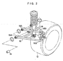
- Each of the force sensors 14 may be incorporated into a suspension component, or as shown in FIG. 3 , a cylindrical force sensor 14 which is provided with a directivity in the direction of force input may be disposed in a bushing mounting portion 16A or a ball joint mounting portion 16B of a lower arm 16, a bushing mounting portion 18A or a ball joint mounting portion 18B of an upper arm 18, or the like.
- Examples of these force sensors include a strain gage for converting a displacement of a component part into an electric signal, or a piezoelectric device for signalizing a deformation, or an element which is changed in resistance, depending upon the deformation, or the like.
- the force sensor is used to detect a lateral force (a force in the lateral direction of vehicle), however, it may be provided so as to detect an input in the back and force direction or the vertical one with respect to the running direction of the vehicle.
- the force sensor 14FR, the force sensor 14FL, the force sensor 14RR, and the force sensor 14RL are connected to an analyzing apparatus 20.
- the analyzing apparatus 20 corresponds to analyzing computation means, a first memory device, and a second memory device of the present invention, being constituted by a microcomputer having a CPU, an ROM, and an RAM, and the like.
- a display device 22 for displaying the result of analysis, and the like; an output device 24 for outputting the result of analysis, and the like; and an input device 26 for operation of the analyzing apparatus 20, and inputting a variety of pieces of information.
- various storage areas are provided, comprising at least two first storage areas and second storage areas corresponding to the first memory device and the second memory device of the present invention.
- a transmitter-receiver 32 (such as a mobile phone, a computer wireless LAN, or the like) which can wirelessly transmit the result of analysis, and the like may be connected.
- the result of analysis, and the like can be transmitted to, for example, a dealer, a repair shop, a vehicle manager, or the like, through a wireless network, or the like.
- the running stability of the vehicle 10 is capable of being analyzed.
- the measure for analyzing the running stability of the vehicle 10 is not the magnitude itself of the input from the road surface, but the fluctuation of the force or the fluctuation rate, and by analyzing the fluctuation of the force or the fluctuation rate, the analysis is possible.
- the input from the road surface has a component which directly has no great effect on the running stability of the vehicle 10 and a component which directly has a great effect thereon, and it is necessary to separate these from each other. Such separation can be achieved by delimiting the frequencies.
- the air pressure for the respective tires is adjusted to an optimum value, with the suspension/chassis being adjusted to an optimum state by using an alignment tester, or the like.
- Adjustments for creation of optimum states as those of the respective wheels and the vehicle can be carried out, for example, in accordance with the present inventor's application (Japanese Patent Application Laid-Open (JP-A) No. 2000-062039 ) or, the adjustments can be carried out in accordance with the present inventor's application (Japanese Patent Application Laid-Open (JP-A) No. 10-7013 ) with using an apparatus which can input the similar output fluctuation.
- the system is set for the initialize mode; the vehicle 10 tuned for an optimum state is run straight, for example, on a flat road surface for a certain period of time with the steering wheel being held truly straight; and the information about the output of the respective force sensors is stored in the first storage area as the reference value. Thereafter, the system is switched over to the monitor mode for always monitoring the state of the vehicle 10 during running, however, alternatively, the state of the vehicle 10 during running may be compared at intervals.
- the storage of information as mentioned here refers to storing the amount (magnitude) of force and the direction of force (including the time series change) on a time series basis; storing the mean value of the force when running has been made for a certain period of time; storing the fluctuation of the force when running has been made for a certain period of time; and storing the fluctuation rate of the force when running has been made for a certain period of time; and the like, however, the object to be stored may be the output of the respective force sensors that has been variously processed, provided that it is related to the output of the respective force sensors.
- the data sorted by frequency is delimited by a certain period of time, for example, 10 to 30 sec for around 40 km/h, 5 to 10 sec for around 100 km/h, and the like (the data processing interval may exceed the above-mentioned range); the inputs around the center of gravity CG for the vehicle 10 are computed relating to the periods; and for the result, the standard deviation is determined (the processing may be carried out by primarily differentiating or quadratically differentiating the original data, however, in this case, it is necessary to give a sum of squares).
- the yaw moment Mo depending on the state of the inputs and the disturbance when the vehicle 10 as shown in FIG. 3 is running can be expressed by the following equation (1), and further the change in stability (dM) can be expressed by the following equation (2).
- Mo F F ⁇ 1 ⁇ L ⁇ 1 - F Fr ⁇ L ⁇ 2 + F Rr ⁇ L ⁇ 3 - F R ⁇ 1 ⁇ L ⁇ 4
- dM STDEV Mo A / STDEV Mo B
- F (Fl), F (Fr), F (Rr), and F (R1) are the standard deviation of the fluctuation of the respective inputs for the front left wheel 12FL, the front right wheel 12FR, the rear right wheel 12RR, and the rear left wheel 12RL (for example, the standard deviation is determined by measuring the lateral force every 0.20 sec, and taking the amount of fluctuation of the lateral force as the observed value).
- L1 is the distance from the center of gravity CG to the force sensor 14FL for the front left wheel
- L2 is the distance from the center of gravity CG to the force sensor 14FR for the front right wheel
- L3 is the distance from the center of gravity CG to the force sensor 14RL for the rear left wheel
- L4 is the distance from the center of gravity CG to the force sensor 14RR for the rear right wheel.
- STDEV (Mo (B)) is the standard deviation in the initialized mode for the vehicle 10 that suspension/chassis is set to be an optimum state
- STDEV (Mo (A)) is the standard deviation for the vehicle 10 in the monitor mode.
- FIG. 4 (A) shows a change in disturbance yaw moment (the abscissa gives time) for the vehicle 10 (having a toe angle of A deg) (on a speedway at 100 km/h, the embodiment side), and FIG. 4 (B) shows a change in disturbance yaw moment (the abscissa gives time) for the vehicle 10 that is set to be an optimum state (having a toe angle of B deg).
- the positive side of the ordinate in the graph as shown in FIG. 4 denotes the moment in a clockwise direction, while the negative side thereof the moment in a counterclockwise direction.
- FIG. 5 (A) gives data when the internal pressure for one wheel is reduced (to 90 kPa) (on a general road at a speed of 30 to 50 km/h), while FIG. 5 (B) data when all wheels have a proper internal pressure (190 kPa).
- the information stored in the analyzing apparatus 20 such as the stored contents, the result of analysis, and the like, can be taken to the outside through the output device 24. Therefore, the information can be analyzed, and saved for management by use of an external computer.
- the result of analysis, or the like can be displayed on the display device 22.
- the system is set to issue an alarm when the fluctuation (dM (RMS)) exceeds 18%.
- the analyzing apparatus 20 determines that the above-mentioned problem (such as a lowered internal pressure, a change in wheel mounting angle, or the like)occurs in the vehicle 10, and can display a message, such as "Suspension/chassis balance is being unstable, or tire air pressure is being abnormal. Stop running, and check for safety.”, or the like, on the display 22.
- the above-mentioned problem such as a lowered internal pressure, a change in wheel mounting angle, or the like
- the display device 22 may be a dedicated item, a display provided on the instrument panel for the driver's seat, a monitor in the navigation system, or the like.
- an interrupt indication be given.
- an alarm sound may be issued at the same time.
- the transmitter-receiver 32 such as a mobile phone, or the like, connected to the output device 24, the result of analysis, the alarm, or the like, may be transmitted to the dealer, the repair shop, the manager of the vehicle 10, and the like.
- the output device 24 may be connected to a system which performs information transmission to the dealer, the manager of the vehicle 10, the nearest repair shop, and the like, as well as guidance to the nearest facility which can make repair, the nearest relief facility, or the like, through the wireless network.
- the input from the wheel is referenced, thus even when the tire or suspension/chassis is replaced, recalibration can be carried out to provide an optimum state according to the suspension/chassis as the reference.
- a change in behavior of the vehicle due to a change in alignment can also be monitored, thus a time dependent change of the suspension, and a possibility of the wheel mounting state being changed by rough road running can be detected for promotion of repair.
- the phenomenon which occurs when the tire internal pressure is lowered or varied with respect to that at the time of setting can be detected as a change in wheel behavior, thus a change in internal pressure can be grasped as a reduction in running stability due to a change of the suspension/chassis, and alarm can be given.
- This vehicle state analyzing system may be connected to the alignment adjustment apparatus for the vehicle for exchange of information.
- this vehicle state analyzing system can also be combined with the application (Japanese Patent Application Laid-Open (JP-A) No. 2000-062039 ) of the present inventor for managing, monitoring, setting, and correcting the information pertaining to the running stability of the vehicle 10.
- JP-A Japanese Patent Application Laid-Open
- the present embodiment is provided with a function which, when there occurs a problem with the state of the vehicle 10, automatically corrects the state to an optimum one on the basis of the result of analysis.
- FIG. 6 and FIG. 7 schematically show the suspension for the vehicle 10.
- FIG. 6 which is a plan view of the suspension
- the sign 34 indicates a tire
- the sign 36 a knuckle
- the sign 38 a camber control arm
- the sign 40 a toe control arm
- sign 42 a cam bracket holding an eccentric cam (not shown) for toe angle ( ⁇ t) adjustment
- the sign 44 an angle adjusting motor for turning the eccentric cam.
- FIG. 7 which is a front view of the suspension, the sign 46 indicates a cam bracket holding an eccentric cam (not shown) for camber angle ( ⁇ k) adjustment, and the sign 48 an angle adjusting motor for turning the eccentric cam, the sign 50 a lower arm.
- the angle adjustment motor 44, and the angle adjustment motor 48 are configured such that rotations thereof are controlled by the analyzing apparatus 20.
- the driver, or the like when an alarm is displayed on the display device 22, the driver, or the like, will request adjustment of the suspension/chassis for the vehicle 10, or filling the tires with air of the dealer, the repair shop, or the like, however, in the present embodiment, the fluctuation (dM (RMS)) can be monitored to adjust the toe angle and the camber angle such that the value of fluctuation does not exceed 18%, for example, and preferably is close to zero.
- This vehicle 10 can also address the problem of running stability related to the wheel mounting angle, as well as the time dependent change of the suspension/chassis, and the change in adjustment of the suspension/chassis, and can maintain the running stability in the straight running state.
- the force sensor 14FR, the force sensor 14FL, the force sensor 14RR, and the force sensor 14RL, the analyzing apparatus 20 (corresponding to the analyzing computation means, the first memory device, and the second memory device of the present invention), the display device 22 for displaying the result of analysis, or the like, the output device 24 for outputting the result of analysis, or the like, to the outside, and the adjusting means for automatically adjusting the alignment of the suspension may be provided in the vehicle, respectively, or outside the vehicle, for example, in a shop, or the like.
- the force sensor 14FR, the force sensor 14FL, the force sensor 14RR, and the force sensor 14RL, the analyzing apparatus 20 (corresponding to the analyzing computation means, the first memory device, and the second memory device of the present invention), the display device 22 for displaying the result of analysis, or the like, the output device 24 for outputting the result of analysis, or the like, to the outside, and the adjusting means for automatically adjusting the alignment of the suspension may all be provided outside the vehicle (which is a first pattern); only the force sensor 14FR, the force sensor 14FL, the force sensor 14RR, and the force sensor 14RL, the second memory device in the analyzing apparatus 20 may be provided in the vehicle, the others being provided outside the vehicle (which is a second pattern); only the force sensor 14FR, the force sensor 14FL, the force sensor 14RR, and the force sensor 14RL, the first memory device and the second memory device in the analyzing apparatus 20 may be provided in the vehicle, the others being provided outside the vehicle (which is a third pattern); the force sensor 14FR, the force sensor 14FL,
- data exchange can be carried out with a mobile phone, a car navigation having a communication capability, or the like.
- the analyzing apparatus 20 determines whether the respective components, such as the force sensor 14FR, the force sensor 14FL, the force sensor 14RR, and the force sensor 14RL, the analyzing apparatus 20, the display device 22, the output device 24, the adjusting means for automatically adjusting the alignment of the suspension, and the like, are to be provided on the shop side or on the vehicle side can be selected as appropriate, and if the number of components which are mounted in the vehicle is decreased, the cost burden on the driver (user) side can be reduced.
- the vehicle state analyzing system, the vehicle, and the vehicle state management system pertaining to the present invention can be advantageously used in analyzing the state of the vehicle.
Landscapes
- Engineering & Computer Science (AREA)
- Mechanical Engineering (AREA)
- Vehicle Body Suspensions (AREA)
Abstract
Description
- The present invention relates to a vehicle state analyzing system for analyzing the state of a vehicle, a vehicle provided with a vehicle state analyzing system, and a vehicle state management system for managing the state of a vehicle.
- Modem vehicles (so-called automobiles) are provided with various apparatuses for detecting the state thereof.
- For example, as a low internal pressure alarm device for the tire, the direct type device which directly measures the internal pressure for issuing an alarm, and the indirect type device which detects a change in tire revolution speed resulting from a change in rolling radius due to a change in tire internal pressure for issuing an alarm have been developed.
- However, the former uses radio wave for signal transmission to or from a revolving wheel, thus the power supply contained in the rotating element presents technical and durability problems, while the latter gives convenience including the device commonness to the ABS (anti-lock braking system), and the like, but any of the devices of this type has functions specified for the internal pressure of the tire, and is not a system which offers information including that about a change in running stability of the vehicle.
- In addition, a system which is used in conjunction with the ABS, the TCS (traction control system), or the like, is difficult to accommodate a change when the tire is changed or when the characteristics of the suspension/chassis of the vehicle are changed, thus involving difficulties in adding the user's preference, such as a desired change of the tire, to the vehicle.
- Although a contrivance for stabilizing the vehicle behavior by detecting the occurrence of a yaw moment in the vehicle, and combining the result with the braking of the wheels has been created, such a control falls in the category of control of a relatively large vehicle behavior, such as understeering or oversteering when turning, or the like, providing a mechanism which carries out control by detecting a change in yaw that is caused when the vehicle turning, and which primary object is to control after the occurrence of a yaw.
- Further, a system which detects a change in a vehicle body acceleration to control the drive force distribution, and when the running stability of the vehicle is deteriorated, prevents such a phenomenon from proceeding, has been devised (TCS). Such a system is for stabilizing the attitude in cornering (for prevention of spinning, and the like), and is not for a technique in which, for the running stability in pseudo straight running within the minute steering angle region, which is frequently utilized in general running, with grasping a phenomenon of the source which causes a yaw to occur from the motion of the respective wheels, tendency thereof is monitored, or an alignment adjustment which causes the problem is related.
- In addition, such a system aims at a control which covers a generated fluctuation in yaw and an occurred change in vehicle acceleration, on the presumption that the initial state of the vehicle varies from vehicle to vehicle, Thus, such a system does not reference to the initial state of the running stability of the vehicle for monitoring and maintaining it, and does not find a problem with a change in internal pressure, an alignment change, or the like.
- In other words, the prior art has been only a measure against a phenomenon which has already occurred, and not an art which monitors the source for occurrence of a phenomenon to relate it to the necessity for repair or fault alarming.
- Any vehicle can be checked for alignment by using an alignment tester, but the alignment tester cannot examine for fluctuation of the alignment of the vehicle in normal actual running.
-
US6,275,753 ,EP0,982,566 andJP2002082021 JP07 223516 - In addition, no art has been available which, when the alignment has been changed due to some factor, such as a time dependent change (a change with passage of time), or the like, automatically adjusts the alignment such that the running stability of the vehicle is not deteriorated.
- Further, a method is available which measures the magnitude of a lateral force by use of a platform tester, and adjusts the lateral force to be within the specified tolerance (reference range), but the method will not allow examining the fluctuation of the lateral force to the vehicle when the vehicle normal running.
- The purpose of the present invention is to eliminate the drawbacks of the above-mentioned prior art, and to provide a vehicle state analyzing system, a vehicle, and a vehicle state management system which can grasp a problem of the state of a vehicle in normal running, such as the running stability related to the wheel mounting angle which depends on the characteristics of the tire, the time dependent change of the suspension/chassis or the change in adjustment of the suspension, the change in internal pressure of the tire, and the like.
- A vehicle state analyzing method is provided, as stated in claim 1.
- Next, the operation the vehicle state analyzing method as stated in claim 1 will be described.
- The running stability of a vehicle is determined by balance of fluctuation of force inputted to the suspension/chassis through the tire.
- However, these fluctuation of force depends upon the distribution of the load caused by the state of the suspension/chassis of the vehicle and the vehicle body, the tolerance (error) for mounting position of the suspension, mounting of the wheel, construction of the tire, and the dispersion as an industrial product.
- Therefore, the running stability can be managed by monitoring and analyzing, with the input from the road surface which is optimal for each vehicle as being a reference value, the disparate from the current situation.
- With the vehicle state analyzing method as stated in claim 1, the vehicle which is set to be an optimum suspension/chassis state is first run for a certain period of time under a predetermined condition, such as the straight running, or the like, to measure the fluctuation or fluctuation rate of the lateral force in the vehicle (the first measuring step).
- The state of the vehicle may change, depending upon the use thereof, thus after having been run or used to some extent, the vehicle is run under the predetermined condition in the same manner as at the previous time to measure the fluctuation or fluctuation rate of the lateral force in the vehicle (the second measuring step).
- Then, by comparing and computing the measured value obtained at the first measuring step and the measured value obtained at the second measuring step (the comparing and computing step), the state of the vehicle can be analyzed.
- For example, when the toe angle, the camber angle, the internal pressure for the tire, or the like, is changed in the vehicle, the inputs of forces from the wheels to the vehicle body are changed.
- Therefore, according to this vehicle state analyzing method, a change from an optimum suspension/chassis state that is caused by a change in state of the vehicle, such as that in toe angle, camber angle, internal pressure for tire, or the like, can be grasped.
- As described above, according to the vehicle state analyzing method as stated in claim 1, an effect that the problem of the running stability related to the wheel mounting angle which depends on the characteristics of the tire, the time dependent change of the suspension/chassis or the adjustment change of the suspension, the change in internal pressure of the tire, and the like can be grasped, is obtained.
- In the invention as stated in claim 2 according to the vehicle state analyzing method of claim 1, the fluctuation or the fluctuation rate of the lateral force is measured when normal running of the vehicle.
- Next, the operation of the vehicle state analyzing system as stated in claim 2 will be described.
- With the vehicle state analyzing method as stated in claim 2, the fluctuation or fluctuation rate of the lateral force is measured in normal running of the vehicle. Therefore, the state of the vehicle in normal running can be known.
- Herein, the phrase "when normal running" refers to a case where the user (the driver) runs on a general normal road surface with a vehicle, and different for a case in which where the vehicle runs on a test road surface on a platform tester, or the like.
- The invention as stated in claim 3 is a vehicle state analyzing system for analyzing state of a vehicle having wheels, comprising: measuring means, provided in the vehicle, for measuring fluctuation or fluctuation rate of lateral force inputted to the vehicle through the wheel; and computing means for computing time dependent change of data measured by the measuring means.
- Next, the operation of the vehicle state analyzing system as stated in claim 3 will be described.
- A second aspect of the invention provides a vehicle state analysing system as claimed in claim 3.
- Next, the operation of the vehicle state analyzing system as stated in claim 3 will be described.
- With the vehicle state analyzing system as stated in claim 3, the vehicle which is set to be the optimum suspension/chassis state is first run for a certain period of time under a predetermined condition, such as the straight running, or the like, for storing the information related to the output of the force sensor in the first memory means as the reference value.
- The state of the vehicle may change, depending upon the use thereof, thus it is run under the predetermined condition in the same manner as when the reference value has been stored as appropriate, for storing the information related to the output of the force sensor in the second memory means.
- The analyzing computation means monitors the output of the force sensor, however, the term "monitors" herein includes not only grasping of the output information at any time (continuously) or every certain interval, but also unscheduled grasping.
- Then, by the analyzing computation means, the state of the vehicle can be analyzed on the basis of the information stored in the first memory means and the information stored in the second memory means.
- Herein, at least one of the information stored in the first memory means, the information stored in the second memory means, and the result of analysis obtained by the analyzing computation means can be outputted by the information output means, and these information and the result of analysis can be utilized when, for example, the state of the vehicle is to be reset to the optimum state.
- For example, when the toe angle, the camber angle, the internal pressure for the tire, or the like, is changed in the vehicle, the input of force from the wheel to the vehicle body is changed.
- Therefore, according to this vehicle state analyzing system, the change from the optimum suspension/chassis state which change is caused by the change in state of the vehicle, such as that in toe angle, camber angle, internal pressure for tire, or the like, can be grasped.
- As described above, according to the vehicle state analyzing system as stated in claim 4, an effect that the problem of the running stability related to the wheel mounting angle which depends on the characteristics of the tire, the time dependent change of the suspension/chassis or the adjustment change of the suspension, the change in internal pressure of the tire, and the like can be grasped, is obtained.
- In the invention as stated in claim 5 according to the vehicle state analyzing system of claim 4, the force sensor is provided in the vehicle, the first memory means, the second memory means, the analyzing computation means, and the information output means are provided outside the vehicle.
- Next, the operation of the vehicle state analyzing system as stated in claim 5 will be described.
- With the vehicle state analyzing system as stated in claim 4, only the force sensor is provided on the vehicle, thus the configuration on the vehicle side is simplified.
- A third aspect of the invention provides a vehicle as claimed in claim 5.
- The information related to the output of the force sensor in normal running of the vehicle is transmitted to the outside of the vehicle, and can be analyzed outside the vehicle.
- The invention as stated in claim 5 is a vehicle on which the vehicle state analyzing system of claim 4 is mounted.
- Next, with the vehicle as stated in claim 5, the vehicle state analyzing system of claim 4 is mounted, thus the vehicle state can be analyzed on the vehicle side while the vehicle is running.
- The invention as stated in claim 6 is a vehicle comprising: the vehicle state analyzing system of claim 3; and display means for displaying the state of the vehicle obtained by the analyzing computation means.
- Next, the operation of the vehicle as stated in claim 6 will be described.
- With the vehicle as stated in claim 8, the state of the vehicle analyzed by the analyzing computation means is displayed on the display means, and the state of the vehicle can be told to the driver, the manager of the vehicle, and the like. For example, in such a case as when the state of the vehicle is changed to worse state than the state which has been preset, attention can be inspired to the driver, the manager of the vehicle, and the like, by the display means.
- Therefore, an effect that the driver can grasp, with the display means, the state of the vehicle analyzed by the analyzing computation means can be provided.
- The invention as stated in claim 7 is a vehicle comprising: the vehicle state analyzing system of claim 3; and adjustment means for automatically adjusting alignment of a suspension on the basis of the state of the vehicle analyzed by the analyzing computation means.
- Next, the operation of the vehicle as stated in claim 7 will be described.
- With the vehicle as stated in claim 7, the adjustment means automatically adjusts the alignment of the suspension on the basis of the state of the vehicle analyzed by the analyzing computation means.
- Therefore, the initial running performance of the vehicle that is rendered optimum can be maintained over a long period of time.
- The invention as stated in claim 8 is a vehicle state management system comprising: the vehicle state analyzing system of claim 3; and a vehicle testing apparatus having a substantially flat road surface for running which causes the wheels to be rotated, detecting the state of the vehicle from outside, and being capable of storing the state of the vehicle detected from the outside and the state of the vehicle analyzed by the vehicle state analyzing system.
- Next, the operation of the vehicle state management system as stated in claim 8 will be described.
- With the vehicle state management system as stated in
claim 10, the vehicle testing apparatus can detect and store the state of the vehicle (such as alignment of the suspension, or the like) when turning of the wheel is stopped, and the state of the vehicle (such as the lateral force acting on the wheel, or the like) when the wheel is rotated on the road surface for running. - In addition, the vehicle testing apparatus can also store the state of the vehicle that has been analyzed by the vehicle state analyzing system.
- Therefore, the vehicle testing apparatus can store and manage various pieces of information related to the running stability of the vehicle, and on the basis of these pieces of information, can adjust the vehicle to be the optimum state.
-
-
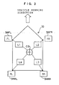
FIG. 1 is a configuration drawing of the system; -
FIG. 2 is a perspective side view of the suspension; -
FIG. 3 is an explanatory drawing illustrating the moment acting on the vehicle; -
FIG. 4 (A) provides data when the toe angle is A deg; -
FIG. 4 (B) provides data when the toe angle is B deg; -
FIG. 5 (A) provides data when the internal pressure for one wheel is reduced; -
FIG. 5 (B) provides data when a proper internal pressure is given; -
FIG. 6 is a plan view of the suspension; and -
FIG. 7 is a front view of the suspension. - Hereinbelow, with reference to the drawings, an embodiment of the vehicle state analyzing system of the present invention will be described in detail.
- As shown in
FIG. 1 , avehicle 10 comprises a force sensor 14FR for detecting the force inputted from a front right wheel 12FR to a vehicle body (not shown), a force sensor 14FL for detecting the force inputted from a front left wheel 12FL to the vehicle body, a force sensor 14RR for detecting the force inputted from a rear right wheel 12RR to the vehicle body, and a force sensor 14FL for detecting the force inputted from a rear left wheel to the vehicle body. - In the present embodiment, the force sensor 14FR, the force sensor 14FL, the force sensor 14RR, and the force sensor 14RL are provided in portions of the suspensions that are subjected to a lateral force, respectively.
- For example, in the front wheels, the force sensor can be provided in a ball joint supporting part in a tip end portion of the lower arm in the suspension, or in a bearing part, a bush part, or the like, in a mounting part of the lower arm to the vehicle body (for both the front wheel and the rear wheel).
- In addition, depending upon the location of a supporting point, for the front wheel, the force sensor can be provided at a tie rod end of a steering portion, and for the rear wheel, the force sensor can be provided at an end portion of a toe control arm (suspension arm).
- Each of the
force sensors 14 may be incorporated into a suspension component, or as shown inFIG. 3 , acylindrical force sensor 14 which is provided with a directivity in the direction of force input may be disposed in abushing mounting portion 16A or a ball joint mountingportion 16B of alower arm 16, abushing mounting portion 18A or a ball joint mountingportion 18B of anupper arm 18, or the like. - Examples of these force sensors include a strain gage for converting a displacement of a component part into an electric signal, or a piezoelectric device for signalizing a deformation, or an element which is changed in resistance, depending upon the deformation, or the like.
- In the present embodiment, the force sensor is used to detect a lateral force (a force in the lateral direction of vehicle), however, it may be provided so as to detect an input in the back and force direction or the vertical one with respect to the running direction of the vehicle.
- As shown in
FIG. 1 , the force sensor 14FR, the force sensor 14FL, the force sensor 14RR, and the force sensor 14RL are connected to an analyzingapparatus 20. - The analyzing
apparatus 20 corresponds to analyzing computation means, a first memory device, and a second memory device of the present invention, being constituted by a microcomputer having a CPU, an ROM, and an RAM, and the like. - In the analyzing
apparatus 20, adisplay device 22 for displaying the result of analysis, and the like; anoutput device 24 for outputting the result of analysis, and the like; and aninput device 26 for operation of the analyzingapparatus 20, and inputting a variety of pieces of information. - In a
memory device 28 of the analyzingapparatus 20, various storage areas are provided, comprising at least two first storage areas and second storage areas corresponding to the first memory device and the second memory device of the present invention. - To the analyzing
apparatus 20, a transmitter-receiver 32 (such as a mobile phone, a computer wireless LAN, or the like) which can wirelessly transmit the result of analysis, and the like may be connected. The result of analysis, and the like, can be transmitted to, for example, a dealer, a repair shop, a vehicle manager, or the like, through a wireless network, or the like. - Next, an example of way of using the vehicle state analyzing system of the present embodiment will be described.
- In the vehicle state analyzing system of the present embodiment, the running stability of the
vehicle 10 is capable of being analyzed. - The measure for analyzing the running stability of the
vehicle 10 is not the magnitude itself of the input from the road surface, but the fluctuation of the force or the fluctuation rate, and by analyzing the fluctuation of the force or the fluctuation rate, the analysis is possible. - In the present embodiment, by applying the standard deviation for the lateral force to the following equations (1) and (2) (which are previously stored in the analyzing apparatus 20) to determine the moment Mo around the center of gravity CG of the
vehicle 10, and compare it with the value when thevehicle 10 is run in an optimum state for a certain period of time, changes in air pressure of the tire and state of the suspension/chassis are detected, and the result of detection can be displayed. - First, the input from the road surface has a component which directly has no great effect on the running stability of the
vehicle 10 and a component which directly has a great effect thereon, and it is necessary to separate these from each other. Such separation can be achieved by delimiting the frequencies. - Herein, the fluctuation in input that is generated at 15 Hz or higher has been specified to be the object
- For the
vehicle 10, the air pressure for the respective tires is adjusted to an optimum value, with the suspension/chassis being adjusted to an optimum state by using an alignment tester, or the like. - Adjustments for creation of optimum states as those of the respective wheels and the vehicle can be carried out, for example, in accordance with the present inventor's application (Japanese Patent Application Laid-Open (JP-A) No.
2000-062039 10-7013 - Next, the system is set for the initialize mode; the
vehicle 10 tuned for an optimum state is run straight, for example, on a flat road surface for a certain period of time with the steering wheel being held truly straight; and the information about the output of the respective force sensors is stored in the first storage area as the reference value. Thereafter, the system is switched over to the monitor mode for always monitoring the state of thevehicle 10 during running, however, alternatively, the state of thevehicle 10 during running may be compared at intervals. - The storage of information as mentioned here refers to storing the amount (magnitude) of force and the direction of force (including the time series change) on a time series basis; storing the mean value of the force when running has been made for a certain period of time; storing the fluctuation of the force when running has been made for a certain period of time; and storing the fluctuation rate of the force when running has been made for a certain period of time; and the like, however, the object to be stored may be the output of the respective force sensors that has been variously processed, provided that it is related to the output of the respective force sensors.
- In the present embodiment, the data sorted by frequency is delimited by a certain period of time, for example, 10 to 30 sec for around 40 km/h, 5 to 10 sec for around 100 km/h, and the like (the data processing interval may exceed the above-mentioned range); the inputs around the center of gravity CG for the
vehicle 10 are computed relating to the periods; and for the result, the standard deviation is determined (the processing may be carried out by primarily differentiating or quadratically differentiating the original data, however, in this case, it is necessary to give a sum of squares). - The yaw moment Mo depending on the state of the inputs and the disturbance when the
vehicle 10 as shown inFIG. 3 is running can be expressed by the following equation (1), and further the change in stability (dM) can be expressed by the following equation (2).

where F (Fl), F (Fr), F (Rr), and F (R1) are the standard deviation of the fluctuation of the respective inputs for the front left wheel 12FL, the front right wheel 12FR, the rear right wheel 12RR, and the rear left wheel 12RL (for example, the standard deviation is determined by measuring the lateral force every 0.20 sec, and taking the amount of fluctuation of the lateral force as the observed value). - L1 is the distance from the center of gravity CG to the force sensor 14FL for the front left wheel; L2 is the distance from the center of gravity CG to the force sensor 14FR for the front right wheel; L3 is the distance from the center of gravity CG to the force sensor 14RL for the rear left wheel; and L4 is the distance from the center of gravity CG to the force sensor 14RR for the rear right wheel.
- STDEV (Mo (B)) is the standard deviation in the initialized mode for the
vehicle 10 that suspension/chassis is set to be an optimum state, and STDEV (Mo (A)) is the standard deviation for thevehicle 10 in the monitor mode. - Hereinbelow, the results of the experiment carried out with the use of a passenger car having an engine displacement of 1800 cc that are processed by using the above equations are given.
-
FIG. 4 (A) shows a change in disturbance yaw moment (the abscissa gives time) for the vehicle 10 (having a toe angle of A deg) (on a speedway at 100 km/h, the embodiment side), andFIG. 4 (B) shows a change in disturbance yaw moment (the abscissa gives time) for thevehicle 10 that is set to be an optimum state (having a toe angle of B deg). The positive side of the ordinate in the graph as shown inFIG. 4 denotes the moment in a clockwise direction, while the negative side thereof the moment in a counterclockwise direction. - In this experiment, dM = STDEV (Mo (A)) / STDEV (Mo (B)) (0.29/0.25 (1.16 is obtained.
- From
FIG. 4 (A), and FIG. 4 (B) , it can be seen that the fluctuation in course of thevehicle 10 due to the disturbance inputs in a case of a toe angle being A deg obviously differs from that in a case of a toe angle being B deg, and the stability for a toe angle of B deg is higher. - Hereinbelow, the driver's evaluation (on a 0 to 10 point scale evaluation) in the experiment is given.
Table 1 Toe angle A deg Toe angle B deg Score 7.0- 7.0 Comment It seems car is difficult to be affected by the irregularities of road surface, but is slightly susceptible to lateral wind. Score is slightly below 7.0. Car is difficult to be affected by the irregularities of road surface. It gives a good running stability with less disturbance. - Herein, an example in which the toe angle is changed has been given, however, also when any other mounting angle, such as the camber angle, or the like, is changed, the moment is changed in the same manner.
- In addition, if any one of all the wheels is changed in mounting angle, the moment is changed in the same manner, and thus the change in state of the
vehicle 10 can be grasped. - Next, the results of the same test conducted for the
vehicle 10 in which air is exhausted from one wheel of all the wheels will be given. - It is understood that, as the air pressure for a tire is decreased, the rigidity of the tire supporting the
vehicle 10 is changed, and thus the balance among the inputs from the respective wheels is changed, resulting in change in yaw moment around the center of gravity CG for the vehicle. -
FIG. 5 (A) gives data when the internal pressure for one wheel is reduced (to 90 kPa) (on a general road at a speed of 30 to 50 km/h), whileFIG. 5 (B) data when all wheels have a proper internal pressure (190 kPa). - In this experiment, dM (STDEV (Mo (A)) / STDEV (Mo (B)) (0.295/0.237 (1.24 is obtained.
- By examining not only the moment, but also the change in input for each wheel, or comparing the inputs of the right and left wheels, which wheel the mounting angle has been displaced or which wheel the internal pressure is abnormal is also made possible to be grasped.
- In the present embodiment, the information stored in the analyzing
apparatus 20, such as the stored contents, the result of analysis, and the like, can be taken to the outside through theoutput device 24. Therefore, the information can be analyzed, and saved for management by use of an external computer. - In addition, in the present embodiment, the result of analysis, or the like, can be displayed on the
display device 22. - Specifically, the system is set to issue an alarm when the fluctuation (dM (RMS)) exceeds 18%.
- When the dM (RMS) value reaches the alarm criterion which is set, and this state continues for a certain period of time (5 min, for example), the analyzing
apparatus 20 determines that the above-mentioned problem (such as a lowered internal pressure, a change in wheel mounting angle, or the like)occurs in thevehicle 10, and can display a message, such as "Suspension/chassis balance is being unstable, or tire air pressure is being abnormal. Stop running, and check for safety.", or the like, on thedisplay 22. - The
display device 22 may be a dedicated item, a display provided on the instrument panel for the driver's seat, a monitor in the navigation system, or the like. When thedisplay device 22 is not a dedicated item, it is preferable that, when a problem occurs, an interrupt indication be given. When a problem occurs, an alarm sound may be issued at the same time. - In addition, from the transmitter-
receiver 32, such as a mobile phone, or the like, connected to theoutput device 24, the result of analysis, the alarm, or the like, may be transmitted to the dealer, the repair shop, the manager of thevehicle 10, and the like. - The
output device 24 may be connected to a system which performs information transmission to the dealer, the manager of thevehicle 10, the nearest repair shop, and the like, as well as guidance to the nearest facility which can make repair, the nearest relief facility, or the like, through the wireless network. - According to the present embodiment, the input from the wheel is referenced, thus even when the tire or suspension/chassis is replaced, recalibration can be carried out to provide an optimum state according to the suspension/chassis as the reference.
- A change in behavior of the vehicle due to a change in alignment can also be monitored, thus a time dependent change of the suspension, and a possibility of the wheel mounting state being changed by rough road running can be detected for promotion of repair.
- The phenomenon which occurs when the tire internal pressure is lowered or varied with respect to that at the time of setting can be detected as a change in wheel behavior, thus a change in internal pressure can be grasped as a reduction in running stability due to a change of the suspension/chassis, and alarm can be given.
- Because the respective force sensors are incorporated in the ball joint or the suspension arm bushing which can be incorporated as a suspension fitting equipment, there is no need for a special power supply, a transmitting-reception apparatus, and the like.
- This vehicle state analyzing system may be connected to the alignment adjustment apparatus for the vehicle for exchange of information.
- For example, this vehicle state analyzing system can also be combined with the application (Japanese Patent Application Laid-Open (JP-A) No.
2000-062039 vehicle 10. - Next, a second embodiment of the present invention will be described hereinbelow. The same component as in the first embodiment will be provided with the same sign, and the description thereof will be omitted.
- The present embodiment is provided with a function which, when there occurs a problem with the state of the
vehicle 10, automatically corrects the state to an optimum one on the basis of the result of analysis. -
FIG. 6 and FIG. 7 schematically show the suspension for thevehicle 10. - In
FIG. 6 , which is a plan view of the suspension, thesign 34 indicates a tire, the sign 36 a knuckle, the sign 38 a camber control arm, the sign 40 a toe control arm, sign 42 a cam bracket holding an eccentric cam (not shown) for toe angle (θt) adjustment, and thesign 44 an angle adjusting motor for turning the eccentric cam. - In addition, in
FIG. 7 , which is a front view of the suspension, thesign 46 indicates a cam bracket holding an eccentric cam (not shown) for camber angle (θk) adjustment, and thesign 48 an angle adjusting motor for turning the eccentric cam, the sign 50 a lower arm. - Herein, the
angle adjustment motor 44, and theangle adjustment motor 48 are configured such that rotations thereof are controlled by the analyzingapparatus 20. - In the above-mentioned first embodiment, when an alarm is displayed on the
display device 22, the driver, or the like, will request adjustment of the suspension/chassis for thevehicle 10, or filling the tires with air of the dealer, the repair shop, or the like, however, in the present embodiment, the fluctuation (dM (RMS)) can be monitored to adjust the toe angle and the camber angle such that the value of fluctuation does not exceed 18%, for example, and preferably is close to zero. - When the camber angle, and the toe angle are automatically adjusted, a display of "Camber angle automatically adjusted.", "Toe angle automatically adjusted.", or the like, may be given.
- In addition, in a case in which the adjustment ranges for the camber angle and the toe angle are previously set, and when the camber angle and/or the toe angle exceeds the adjustment ranges, it can be considered that the state of the
vehicle 10 has become worse due to some other factor, such as air pressure, or the like, thus in such a case, it is recommended to issue an alarm on thedisplay device 22. - This
vehicle 10 can also address the problem of running stability related to the wheel mounting angle, as well as the time dependent change of the suspension/chassis, and the change in adjustment of the suspension/chassis, and can maintain the running stability in the straight running state. - The force sensor 14FR, the force sensor 14FL, the force sensor 14RR, and the force sensor 14RL, the analyzing apparatus 20 (corresponding to the analyzing computation means, the first memory device, and the second memory device of the present invention), the
display device 22 for displaying the result of analysis, or the like, theoutput device 24 for outputting the result of analysis, or the like, to the outside, and the adjusting means for automatically adjusting the alignment of the suspension may be provided in the vehicle, respectively, or outside the vehicle, for example, in a shop, or the like. - For example, the force sensor 14FR, the force sensor 14FL, the force sensor 14RR, and the force sensor 14RL, the analyzing apparatus 20 (corresponding to the analyzing computation means, the first memory device, and the second memory device of the present invention), the display device 22 for displaying the result of analysis, or the like, the output device 24 for outputting the result of analysis, or the like, to the outside, and the adjusting means for automatically adjusting the alignment of the suspension may all be provided outside the vehicle (which is a first pattern); only the force sensor 14FR, the force sensor 14FL, the force sensor 14RR, and the force sensor 14RL, the second memory device in the analyzing apparatus 20 may be provided in the vehicle, the others being provided outside the vehicle (which is a second pattern); only the force sensor 14FR, the force sensor 14FL, the force sensor 14RR, and the force sensor 14RL, the first memory device and the second memory device in the analyzing apparatus 20 may be provided in the vehicle, the others being provided outside the vehicle (which is a third pattern); the force sensor 14FR, the force sensor 14FL, the force sensor 14RR, and the force sensor 14RL, the analyzing apparatus 20 (corresponding to the analyzing computation means, the first memory device, and the second memory device of the present invention), and the output device 24 for outputting the result of analysis, or the like, to the outside may be provided in the vehicle, the others being provided outside the vehicle (which is a fourth pattern); the adjusting means for automatically adjusting the alignment of the suspension may be provided outside the vehicle, the others being provided in the vehicle (which is a fifth pattern); the force sensor 14FR, the force sensor 14FL, the force sensor 14RR, and the force sensor 14RL, the analyzing apparatus 20 (corresponding to the analyzing computation means, the first memory device, and the second memory device of the present invention), the display device 22 for displaying the result of analysis, or the like, the output device 24 for outputting the result of analysis, or the like, to the outside, and the adjusting means for automatically adjusting the alignment of the suspension may all be provided in the vehicle (which is a sixth pattern); and the force sensor 14FR, the force sensor 14FL, the force sensor 14RR, and the force sensor 14RL, and a transmission apparatus (not shown) which transmits the information obtained with the respective force sensors wirelessly, or otherwise, to the outside of the vehicle may be provided in the vehicle, the other components being provided outside the vehicle (which is a seventh pattern).
- Between the vehicle and the outside thereof (for example, a shop), data exchange can be carried out with a mobile phone, a car navigation having a communication capability, or the like.
- Whether the respective components, such as the force sensor 14FR, the force sensor 14FL, the force sensor 14RR, and the force sensor 14RL, the analyzing
apparatus 20, thedisplay device 22, theoutput device 24, the adjusting means for automatically adjusting the alignment of the suspension, and the like, are to be provided on the shop side or on the vehicle side can be selected as appropriate, and if the number of components which are mounted in the vehicle is decreased, the cost burden on the driver (user) side can be reduced. - As described above, the vehicle state analyzing system, the vehicle, and the vehicle state management system pertaining to the present invention can be advantageously used in analyzing the state of the vehicle.
Claims (8)
- A vehicle state analyzing method, comprising:a suspension/chassis setting step for setting an optimum alignment state in a suspension/chassis of a vehicle;an initialize mode measuring step in which a lateral force from all wheels to a vehicle body is measured, by using a force sensor for detecting input of force from each wheel to the vehicle body, when the vehicle, which is set to an optimum alignment state, is run on a substantially flat road surface as reference under a predetermined condition, and deviation of fluctuation or fluctuation rate of the lateral force with respect to the optimum alignment state is measured;a monitor mode measuring step in which the lateral force is measured, by using the force sensor, when the vehicle, which has run a distance or for a time from a time of performing the initialise mode measuring step, is run on a substantially flat road surface, and deviation of fluctuation or fluctuation rate of the lateral force with respect to the optimum alignment state is measured; andan analyzing step in which change of the alignment state of the vehicle is analyzed on the basis of a ratio of the deviation obtained at the monitor mode measuring step with respect to the deviation obtained at the initialize mode measuring step.
- A vehicle state analyzing method as claimed in claim 1, wherein the deviation of fluctuation or fluctuation rate of the lateral force is measured when normal running of the vehicle.
- A vehicle state analyzing system for analyzing state of a vehicle (10) having wheels (12), comprising:force sensors (14) for detecting input of force from a respective wheel to a vehicle body;initialize mode memory means (28) in which a lateral force from all wheels to the vehicle body is measured, by using the force sensors for detecting input of force from each wheel to the vehicle body, when the vehicle which is set to an optimum alignment state is run for a first period on a substantially flat road surface as reference under a predetermined condition and deviation of fluctuation or fluctuation rate of the lateral force with respect to the optimum alignment state is measured, and stored;monitor mode memory means (28) in which the lateral force is measured, by using the force sensors, when the vehicle which has run a distance, or for a time from a time of measuring the lateral force by the initialise mode memory means, is run during a second period after the first period on the substantially flat road surface and deviation of fluctuation or fluctuation rate of the lateral force with respect to the optimum alignment state is measured, and stored;analyzing computation means (20) in which change of the alignment state of the vehicle is analyzed on the basis of a ratio of the deviation stored in the monitor mode memory means with respect to the deviation stored in the initialize mode memory means; andinformation output means (22, 24) for outputting at least one of information stored in the initialize mode memory means, information stored in the monitor mode memory means, and the result of analysis obtained by the analyzing computation means.
- A vehicle state analyzing system as claimed in claim 3, wherein the force sensor is provided in the vehicle; and
the initialize mode memory means, the monitor mode memory means, the analyzing computation means, and the information output means are provided outside the vehicle. - A vehicle on which the vehicle state analyzing system of claim 3 or 4 is mounted.
- A vehicle as claimed in claim 5, further comprising display means for displaying the state of the vehicle obtained by the analyzing computation means.
- A vehicle as claimed in claim 5, further comprising adjustment means for automatically adjusting alignment of a suspension on the basis of the state of the vehicle analyzed by the analyzing computation means.
- A vehicle state management system, comprising:the vehicle state analyzing system of claim 3; anda vehicle testing apparatus having the substantially flat road surface for running which causes the wheels to be rotated, detecting the state of the vehicle from outside, and being capable of storing the state of the vehicle detected from the outside and the state of the vehicle analyzed by the vehicle state analyzing system.
Applications Claiming Priority (2)
| Application Number | Priority Date | Filing Date | Title |
|---|---|---|---|
| JP2003097758 | 2003-04-01 | ||
| PCT/JP2004/004779 WO2004089664A1 (en) | 2003-04-01 | 2004-04-01 | Vehicle state analyzing system, vehicle, and vehicle state managing system |
Publications (3)
| Publication Number | Publication Date |
|---|---|
| EP1612067A1 EP1612067A1 (en) | 2006-01-04 |
| EP1612067A4 EP1612067A4 (en) | 2008-05-14 |
| EP1612067B1 true EP1612067B1 (en) | 2011-03-16 |
Family
ID=33156652
Family Applications (1)
| Application Number | Title | Priority Date | Filing Date |
|---|---|---|---|
| EP04725170A Expired - Lifetime EP1612067B1 (en) | 2003-04-01 | 2004-04-01 | Vehicle state analyzing system, vehicle, and vehicle state managing system |
Country Status (6)
| Country | Link |
|---|---|
| US (1) | US7536245B2 (en) |
| EP (1) | EP1612067B1 (en) |
| JP (1) | JP4563935B2 (en) |
| DE (1) | DE602004031826D1 (en) |
| ES (1) | ES2362657T3 (en) |
| WO (1) | WO2004089664A1 (en) |
Cited By (1)
| Publication number | Priority date | Publication date | Assignee | Title |
|---|---|---|---|---|
| DE102023208153A1 (en) | 2023-08-25 | 2025-02-27 | Continental Reifen Deutschland Gmbh | Skew detection for a tire of a vehicle |
Families Citing this family (19)
| Publication number | Priority date | Publication date | Assignee | Title |
|---|---|---|---|---|
| JP4722536B2 (en) * | 2005-04-19 | 2011-07-13 | 富士重工業株式会社 | Vehicle alignment management device |
| JP4542571B2 (en) * | 2007-02-16 | 2010-09-15 | 本田技研工業株式会社 | Alignment change control device |
| JP4977152B2 (en) * | 2009-02-10 | 2012-07-18 | 本田技研工業株式会社 | Rear wheel steering control device |
| WO2010107344A1 (en) * | 2009-03-20 | 2010-09-23 | Volvo Lastvagnar Ab | Method for onboard diagnosis of a wheel alignment of a vehicle and vehicle |
| JP2010221818A (en) * | 2009-03-23 | 2010-10-07 | Honda Motor Co Ltd | Rear wheel control device |
| WO2010117793A2 (en) * | 2009-03-30 | 2010-10-14 | Walter Joel A | Apparatus and method for determining forces acting on a vehicle in a wind tunnel |
| FR3001541B1 (en) * | 2013-01-31 | 2016-02-05 | Michelin & Cie | METHOD FOR CHARACTERIZING THE BEHAVIOR OF A VEHICLE AND APPLICATION FOR CHOOSING THE TIRES OF THE VEHICLE |
| FR3024572B1 (en) * | 2014-07-31 | 2016-09-02 | Continental Automotive France | METHOD FOR CONTROLLING THE SUSPENSION OF A VEHICLE BY PROCESSING IMAGES OF AT LEAST ONE EMBARKED CAMERA |
| JP7153021B2 (en) | 2017-01-19 | 2022-10-13 | ドォフテック ピーティーワイ リミテッド | Electromechanical device for controlling vehicle suspension settings |
| US10424132B2 (en) * | 2017-02-10 | 2019-09-24 | Hitachi, Ltd. | Vehicle component failure prevention |
| JP7151635B2 (en) * | 2019-06-13 | 2022-10-12 | いすゞ自動車株式会社 | Inspection support program and inspection support system |
| DE102019124655A1 (en) | 2019-09-13 | 2021-03-18 | Valeo Schalter Und Sensoren Gmbh | Detection of errors associated with the wheels of a motor vehicle in a driving situation |
| US20210269071A1 (en) * | 2020-03-02 | 2021-09-02 | Westinghouse Air Brake Technologies Corporation | Wheel force measurement systems and methods |
| WO2022077059A1 (en) | 2020-10-13 | 2022-04-21 | Doftek Pty Ltd | Wheel alignment systems |
| CN115092073B (en) * | 2022-06-13 | 2025-05-16 | 摩登汽车有限公司 | Vehicle chassis status monitoring method and system |
| CN115215055B (en) * | 2022-08-08 | 2024-04-30 | 上海中通吉网络技术有限公司 | Method, device and system for solving problem of flying express mail in loop line sorting equipment |
| CN115901287B (en) * | 2022-10-27 | 2025-05-30 | 东风柳州汽车有限公司 | Whole vehicle axle testing method, device, equipment and storage medium |
| KR20250046832A (en) * | 2023-09-27 | 2025-04-03 | 에이치엘만도 주식회사 | Method and Apparatus for Anomaly Detecting of Lane Following Assist |
| CN117774570B (en) * | 2024-01-04 | 2025-11-25 | 江苏克瑞迪机车有限公司 | An intelligent tire monitoring system and method for all-terrain vehicles |
Family Cites Families (9)
| Publication number | Priority date | Publication date | Assignee | Title |
|---|---|---|---|---|
| JPH07223516A (en) * | 1994-02-07 | 1995-08-22 | Digital Stream:Kk | Communication device for automobile maintenance service |
| JP4179674B2 (en) * | 1998-08-21 | 2008-11-12 | 株式会社ブリヂストン | Vehicle wheel alignment adjustment method |
| JP2000318416A (en) * | 1999-03-05 | 2000-11-21 | Toyota Motor Corp | VEHICLE CHARACTERISTIC DETECTION DEVICE AND VEHICLE CONTROL DEVICE EQUIPPED WITH THE DEVICE |
| US6487475B1 (en) * | 1999-12-01 | 2002-11-26 | Honda Giken Kogyo Kabushiki Kaisha | Driving state monitoring apparatus for vehicles |
| US6275753B1 (en) * | 2000-02-15 | 2001-08-14 | Meritor Heavy Vehicle Systems, Llc | Method and system for detecting and adjusting wheel misalignment of a vehicle |
| JP4299446B2 (en) * | 2000-09-11 | 2009-07-22 | 横浜ゴム株式会社 | Evaluation method of tire wandering performance |
| JP4583594B2 (en) * | 2000-12-28 | 2010-11-17 | 富士重工業株式会社 | Vehicle management system |
| EP1219946A3 (en) | 2000-12-28 | 2008-03-12 | Fuji Jukogyo Kabushiki Kaisha | Vehicle management system |
| JP4779246B2 (en) * | 2001-06-28 | 2011-09-28 | トヨタ自動車株式会社 | Tire acting force detection device |
-
2004
- 2004-04-01 WO PCT/JP2004/004779 patent/WO2004089664A1/en not_active Ceased
- 2004-04-01 JP JP2005505245A patent/JP4563935B2/en not_active Expired - Fee Related
- 2004-04-01 US US10/551,562 patent/US7536245B2/en not_active Expired - Fee Related
- 2004-04-01 DE DE602004031826T patent/DE602004031826D1/en not_active Expired - Lifetime
- 2004-04-01 ES ES04725170T patent/ES2362657T3/en not_active Expired - Lifetime
- 2004-04-01 EP EP04725170A patent/EP1612067B1/en not_active Expired - Lifetime
Cited By (2)
| Publication number | Priority date | Publication date | Assignee | Title |
|---|---|---|---|---|
| DE102023208153A1 (en) | 2023-08-25 | 2025-02-27 | Continental Reifen Deutschland Gmbh | Skew detection for a tire of a vehicle |
| EP4516611A1 (en) | 2023-08-25 | 2025-03-05 | Continental Reifen Deutschland GmbH | Skew detection for a tire of a means of transportation |
Also Published As
| Publication number | Publication date |
|---|---|
| DE602004031826D1 (en) | 2011-04-28 |
| ES2362657T3 (en) | 2011-07-11 |
| JPWO2004089664A1 (en) | 2006-07-06 |
| EP1612067A4 (en) | 2008-05-14 |
| US7536245B2 (en) | 2009-05-19 |
| US20070208472A1 (en) | 2007-09-06 |
| WO2004089664A1 (en) | 2004-10-21 |
| JP4563935B2 (en) | 2010-10-20 |
| EP1612067A1 (en) | 2006-01-04 |
Similar Documents
| Publication | Publication Date | Title |
|---|---|---|
| EP1612067B1 (en) | Vehicle state analyzing system, vehicle, and vehicle state managing system | |
| EP3153375B1 (en) | Robust tire forces estimation system | |
| US6526342B1 (en) | Vehicle suspensions | |
| EP1880875B1 (en) | Method, apparatus and program for alarming decrease in tire air-pressure | |
| US20060267750A1 (en) | Tire abnormal state monitoring system for an automotive vehicle | |
| US6650980B2 (en) | Steering wheel torque based detection of misalignment of a vehicle steering system | |
| JP5457201B2 (en) | Use of suspension information in detecting tire pressure deviations in vehicle tires | |
| US20090024269A1 (en) | Method for determining the centre of gravity for an automotive vehicle | |
| JP3158038B2 (en) | Tire pressure drop detector | |
| EP1547828B1 (en) | Method for detecting decompression of tires and device thereof, and program for judging decompression of tires | |
| US20020011929A1 (en) | Method for alarming decrease in tire air-pressure and apparatus used therefor | |
| EP1798077B1 (en) | Apparatus, method and program for alarming decrease in tire air-pressure | |
| EP2243640B1 (en) | Method of determining parameter used in air pressure reduction detecting method | |
| EP1352765B1 (en) | Method and apparatus for detecting decrease in tire-pressure and program for judging decompression of tire | |
| US7032442B2 (en) | Method and apparatus for detecting decrease in tire air-pressure and program for judging decompression of tire | |
| JP3978774B2 (en) | Vehicle control device | |
| EP1332895B1 (en) | Method and apparatus for detecting decrease in tire air-pressure | |
| US7146852B2 (en) | Air pressure detection device | |
| US6907327B2 (en) | Method of detection of limited slip differential device, method and apparatus for detecting decrease in tire air-pressure employing the method of detection, and program for judging decompression of tire | |
| JP2007240392A (en) | Ground load estimation device | |
| EP1454773B1 (en) | Method and apparatus for alarming decrease in tire air-pressure and program for alarming decrease in tire air-pressure | |
| JP3594833B2 (en) | Tire air pressure drop warning method and device | |
| JP4086763B2 (en) | Tire pressure drop detection method and apparatus, and tire decompression determination program | |
| JPH0966714A (en) | Method and apparatus for detecting decrease in tire air pressure | |
| JP3605006B2 (en) | Tire pressure drop warning device and method |
Legal Events
| Date | Code | Title | Description |
|---|---|---|---|
| PUAI | Public reference made under article 153(3) epc to a published international application that has entered the european phase |
Free format text: ORIGINAL CODE: 0009012 |
|
| 17P | Request for examination filed |
Effective date: 20051017 |
|
| AK | Designated contracting states |
Kind code of ref document: A1 Designated state(s): AT BE BG CH CY CZ DE DK EE ES FI FR GB GR HU IE IT LI LU MC NL PL PT RO SE SI SK TR |
|
| AX | Request for extension of the european patent |
Extension state: AL HR LT LV MK |
|
| DAX | Request for extension of the european patent (deleted) | ||
| RBV | Designated contracting states (corrected) |
Designated state(s): DE ES FR GB IT |
|
| A4 | Supplementary search report drawn up and despatched |
Effective date: 20080416 |
|
| 17Q | First examination report despatched |
Effective date: 20091005 |
|
| GRAP | Despatch of communication of intention to grant a patent |
Free format text: ORIGINAL CODE: EPIDOSNIGR1 |
|
| GRAS | Grant fee paid |
Free format text: ORIGINAL CODE: EPIDOSNIGR3 |
|
| GRAA | (expected) grant |
Free format text: ORIGINAL CODE: 0009210 |
|
| AK | Designated contracting states |
Kind code of ref document: B1 Designated state(s): DE ES FR GB IT |
|
| REG | Reference to a national code |
Ref country code: GB Ref legal event code: FG4D |
|
| REF | Corresponds to: |
Ref document number: 602004031826 Country of ref document: DE Date of ref document: 20110428 Kind code of ref document: P |
|
| REG | Reference to a national code |
Ref country code: DE Ref legal event code: R096 Ref document number: 602004031826 Country of ref document: DE Effective date: 20110428 |
|
| REG | Reference to a national code |
Ref country code: ES Ref legal event code: FG2A Ref document number: 2362657 Country of ref document: ES Kind code of ref document: T3 Effective date: 20110711 |
|
| PLBE | No opposition filed within time limit |
Free format text: ORIGINAL CODE: 0009261 |
|
| STAA | Information on the status of an ep patent application or granted ep patent |
Free format text: STATUS: NO OPPOSITION FILED WITHIN TIME LIMIT |
|
| 26N | No opposition filed |
Effective date: 20111219 |
|
| REG | Reference to a national code |
Ref country code: DE Ref legal event code: R097 Ref document number: 602004031826 Country of ref document: DE Effective date: 20111219 |
|
| PGFP | Annual fee paid to national office [announced via postgrant information from national office to epo] |
Ref country code: GB Payment date: 20120328 Year of fee payment: 9 |
|
| PGFP | Annual fee paid to national office [announced via postgrant information from national office to epo] |
Ref country code: IT Payment date: 20120413 Year of fee payment: 9 |
|
| PGFP | Annual fee paid to national office [announced via postgrant information from national office to epo] |
Ref country code: ES Payment date: 20120424 Year of fee payment: 9 |
|
| GBPC | Gb: european patent ceased through non-payment of renewal fee |
Effective date: 20130401 |
|
| PG25 | Lapsed in a contracting state [announced via postgrant information from national office to epo] |
Ref country code: GB Free format text: LAPSE BECAUSE OF NON-PAYMENT OF DUE FEES Effective date: 20130401 |
|
| PG25 | Lapsed in a contracting state [announced via postgrant information from national office to epo] |
Ref country code: IT Free format text: LAPSE BECAUSE OF NON-PAYMENT OF DUE FEES Effective date: 20130401 |
|
| REG | Reference to a national code |
Ref country code: ES Ref legal event code: FD2A Effective date: 20140613 |
|
| REG | Reference to a national code |
Ref country code: DE Ref legal event code: R082 Ref document number: 602004031826 Country of ref document: DE Representative=s name: BARDEHLE PAGENBERG PARTNERSCHAFT MBB PATENTANW, DE |
|
| PG25 | Lapsed in a contracting state [announced via postgrant information from national office to epo] |
Ref country code: ES Free format text: LAPSE BECAUSE OF NON-PAYMENT OF DUE FEES Effective date: 20130402 |
|
| REG | Reference to a national code |
Ref country code: FR Ref legal event code: CA Effective date: 20140812 |
|
| REG | Reference to a national code |
Ref country code: DE Ref legal event code: R081 Ref document number: 602004031826 Country of ref document: DE Owner name: BRIDGESTONE CORPORATION, JP Free format text: FORMER OWNER: BRIDGESTONE TIRE K.K., TOKYO, JP Effective date: 20110217 Ref country code: DE Ref legal event code: R081 Ref document number: 602004031826 Country of ref document: DE Owner name: BRIDGESTONE CORPORATION, JP Free format text: FORMER OWNER: BRIDGESTONE CORP., TOKIO/TOKYO, JP Effective date: 20140828 Ref country code: DE Ref legal event code: R082 Ref document number: 602004031826 Country of ref document: DE Representative=s name: BARDEHLE PAGENBERG PARTNERSCHAFT MBB PATENTANW, DE Effective date: 20140828 |
|
| REG | Reference to a national code |
Ref country code: FR Ref legal event code: PLFP Year of fee payment: 12 |
|
| PGFP | Annual fee paid to national office [announced via postgrant information from national office to epo] |
Ref country code: DE Payment date: 20150421 Year of fee payment: 12 |
|
| PGFP | Annual fee paid to national office [announced via postgrant information from national office to epo] |
Ref country code: FR Payment date: 20150421 Year of fee payment: 12 |
|
| REG | Reference to a national code |
Ref country code: DE Ref legal event code: R119 Ref document number: 602004031826 Country of ref document: DE |
|
| REG | Reference to a national code |
Ref country code: FR Ref legal event code: ST Effective date: 20161230 |
|
| PG25 | Lapsed in a contracting state [announced via postgrant information from national office to epo] |
Ref country code: DE Free format text: LAPSE BECAUSE OF NON-PAYMENT OF DUE FEES Effective date: 20161101 Ref country code: FR Free format text: LAPSE BECAUSE OF NON-PAYMENT OF DUE FEES Effective date: 20160502 |