EP1612019A2 - Misch- und Ausgabekopf - Google Patents
Misch- und Ausgabekopf Download PDFInfo
- Publication number
- EP1612019A2 EP1612019A2 EP05380138A EP05380138A EP1612019A2 EP 1612019 A2 EP1612019 A2 EP 1612019A2 EP 05380138 A EP05380138 A EP 05380138A EP 05380138 A EP05380138 A EP 05380138A EP 1612019 A2 EP1612019 A2 EP 1612019A2
- Authority
- EP
- European Patent Office
- Prior art keywords
- spindle
- valve body
- head
- components
- mixing chamber
- Prior art date
- Legal status (The legal status is an assumption and is not a legal conclusion. Google has not performed a legal analysis and makes no representation as to the accuracy of the status listed.)
- Granted
Links
Images


Classifications
-
- B—PERFORMING OPERATIONS; TRANSPORTING
- B29—WORKING OF PLASTICS; WORKING OF SUBSTANCES IN A PLASTIC STATE IN GENERAL
- B29B—PREPARATION OR PRETREATMENT OF THE MATERIAL TO BE SHAPED; MAKING GRANULES OR PREFORMS; RECOVERY OF PLASTICS OR OTHER CONSTITUENTS OF WASTE MATERIAL CONTAINING PLASTICS
- B29B7/00—Mixing; Kneading
- B29B7/74—Mixing; Kneading using other mixers or combinations of mixers, e.g. of dissimilar mixers ; Plant
- B29B7/76—Mixers with stream-impingement mixing head
- B29B7/7663—Mixers with stream-impingement mixing head the mixing head having an outlet tube with a reciprocating plunger, e.g. with the jets impinging in the tube
-
- B—PERFORMING OPERATIONS; TRANSPORTING
- B29—WORKING OF PLASTICS; WORKING OF SUBSTANCES IN A PLASTIC STATE IN GENERAL
- B29B—PREPARATION OR PRETREATMENT OF THE MATERIAL TO BE SHAPED; MAKING GRANULES OR PREFORMS; RECOVERY OF PLASTICS OR OTHER CONSTITUENTS OF WASTE MATERIAL CONTAINING PLASTICS
- B29B7/00—Mixing; Kneading
- B29B7/74—Mixing; Kneading using other mixers or combinations of mixers, e.g. of dissimilar mixers ; Plant
- B29B7/7404—Mixing devices specially adapted for foamable substances
-
- B—PERFORMING OPERATIONS; TRANSPORTING
- B29—WORKING OF PLASTICS; WORKING OF SUBSTANCES IN A PLASTIC STATE IN GENERAL
- B29B—PREPARATION OR PRETREATMENT OF THE MATERIAL TO BE SHAPED; MAKING GRANULES OR PREFORMS; RECOVERY OF PLASTICS OR OTHER CONSTITUENTS OF WASTE MATERIAL CONTAINING PLASTICS
- B29B7/00—Mixing; Kneading
- B29B7/74—Mixing; Kneading using other mixers or combinations of mixers, e.g. of dissimilar mixers ; Plant
- B29B7/76—Mixers with stream-impingement mixing head
- B29B7/7631—Parts; Accessories
- B29B7/7636—Construction of the feed orifices, bores, ports
-
- B—PERFORMING OPERATIONS; TRANSPORTING
- B29—WORKING OF PLASTICS; WORKING OF SUBSTANCES IN A PLASTIC STATE IN GENERAL
- B29B—PREPARATION OR PRETREATMENT OF THE MATERIAL TO BE SHAPED; MAKING GRANULES OR PREFORMS; RECOVERY OF PLASTICS OR OTHER CONSTITUENTS OF WASTE MATERIAL CONTAINING PLASTICS
- B29B7/00—Mixing; Kneading
- B29B7/74—Mixing; Kneading using other mixers or combinations of mixers, e.g. of dissimilar mixers ; Plant
- B29B7/76—Mixers with stream-impingement mixing head
- B29B7/7663—Mixers with stream-impingement mixing head the mixing head having an outlet tube with a reciprocating plunger, e.g. with the jets impinging in the tube
- B29B7/7684—Parts; Accessories
-
- B—PERFORMING OPERATIONS; TRANSPORTING
- B29—WORKING OF PLASTICS; WORKING OF SUBSTANCES IN A PLASTIC STATE IN GENERAL
- B29B—PREPARATION OR PRETREATMENT OF THE MATERIAL TO BE SHAPED; MAKING GRANULES OR PREFORMS; RECOVERY OF PLASTICS OR OTHER CONSTITUENTS OF WASTE MATERIAL CONTAINING PLASTICS
- B29B7/00—Mixing; Kneading
- B29B7/80—Component parts, details or accessories; Auxiliary operations
- B29B7/82—Heating or cooling
- B29B7/826—Apparatus therefor
-
- B—PERFORMING OPERATIONS; TRANSPORTING
- B29—WORKING OF PLASTICS; WORKING OF SUBSTANCES IN A PLASTIC STATE IN GENERAL
- B29C—SHAPING OR JOINING OF PLASTICS; SHAPING OF MATERIAL IN A PLASTIC STATE, NOT OTHERWISE PROVIDED FOR; AFTER-TREATMENT OF THE SHAPED PRODUCTS, e.g. REPAIRING
- B29C67/00—Shaping techniques not covered by groups B29C39/00 - B29C65/00, B29C70/00 or B29C73/00
- B29C67/24—Shaping techniques not covered by groups B29C39/00 - B29C65/00, B29C70/00 or B29C73/00 characterised by the choice of material
- B29C67/246—Moulding high reactive monomers or prepolymers, e.g. by reaction injection moulding [RIM], liquid injection moulding [LIM]
Definitions
- this invention concerns a mixing-dispensing head for mixing two or more components and dispense the resulting mixture and, more specifically, a mixing-dispensing head for mixing polyol and isocyanate in liquid form in order to produce a polyurethane (PUR) foam, including the means to clean a mixing chamber and associated passages after each mixing operation.
- PUR polyurethane
- the head of this invention is useful in the packaging and commerce sectors, applicable to an automatic appliance for the injection of PUR in plastic bags for the production of protective cushions.
- Patent US-A-4440320 describes a polyurethane foam dispenser device comprising a static mixing chamber and a pair of rotating valves, each one for a different component.
- the valves are operated to simultaneously alternate between one working position, in which each valve communicates a respective components inlet with the mixing chamber and an extended position in which each valve communicates a solvent inlet with the mixing chamber,
- Each valve has a rotating cylindrical body with an interior passage that includes a portion of axial passage that permanently communicates with the mixing chamber, and a portion of radial passage which, when said body rotates, it alternatively communicates with the cited respective component and solvent inlets.
- the portions of axial passage exit at diametrally opposite points within the mixing chamber so that the respective component flows frontally meet together in order to produce the mixture.
- the application for international patent WO 99/06196 describes a dispensing system that consists of a mixing-dispensing head for the injection of PUR into plastic bags.
- the head includes a casing that defines an interior cavity that houses a valve body that forms an interior mixing chamber with an open dispensing end.
- the valves body acts as a launcher and is operated to alternate between a dispensing mode, which allows the components to enter the mixing chamber and a non-dispensing mode.
- a cleaning system is planned, which includes the provision of a solvent flow to the mixing chamber through the components inlet passages when the head is in the non-dispensing mode and through a channel between the valve body and casing.
- a spindle is housed inside the valve body mixing chamber that is mounted to move in an axial direction.
- An annular chamber is defined between an exterior surface of said spindle and an interior surface of the mixing chamber, which allows fluid to pass. The spindle is operated in coordination with the valve body movements between an interference position with the mixing chamber and
- Patent US-A-5586724 makes known a device that produces foam from two components and then to spray it through a nozzle using pressurised gas.
- the device comprises a body with inlet ports for the components and gas inlet ports that communicate with a conical interior cavity.
- This body contains a valve element with an exterior conical wall that is complementary to the interior cavity of the body and this valve element houses a part that forms a mixing chamber with a longitudinal through-hole communication with radial through-holes that open into a recessed annual area facing passages of the valve element that open into said exterior conical wall. Rotation of the valve element in relation to the body will close off the flow of components and connect the flow of gas in order to perform a purge operation.
- the mixing-dispensing head is of the type that comprises a casing that defines an interior cavity with an open end and components inlet ports, at least one solvent inlet port, with said components inlet ports and the solvent inlet and outlet communicating with said interior cavity.
- the interior cavity of said casing contains a valve body that defines some exterior surfaces and an interior mixing chamber, with a dispensing aperture, passages for component entry and at least one solvent inlet passage, where said component and solvent inlet passages extend between openings in said exterior surfaces and said mixing chamber.
- a spindle is housed within the valve body mixing chamber, and between an exterior surface of said spindle and an interior mixing chamber surface, an annular chamber is defined that allows the passage of fluid.
- Some first driving means are connected to alternatively move said valve body between a mixing and dispensing position, in which said components inlet passages communicate with said components inlet ports, and a blocking position, in which at least one of the exterior valve body surfaces shuts off the components inlet ports.
- Some second driving means are connected in order to linearly and alternatively translate the spindle along a longitudinal extended position, in which one end of the spindle limits said mixing chamber dispensing aperture and said passages for solvent entry and exit communicate with said annular chamber, and a retracted position, in which the spindle does not interfere with the movement of components from the mixing chamber components inlet passages and said spindle end forms a bottom to the mixing chamber that facilitates the exit of the mixture to the dispensing aperture.
- the head of this invention is characterised in that the valve body is mounted in a rotating fashion inside the interior cavity of the casing to be alternatively moved between said mixing and dispensing position and said blocked position by rotating around a longitudinal head axis, with some kinematic linkage means between the valve body and the spindle in order to determine that the valve body mixing and dispensing position corresponds to the retracted spindle body and that the valve body blocked position corresponds to the extended spindle position.
- the components inlet passages lead into the mixing chamber in an oblique direction against the exit direction towards the dispensing aperture, thus favouring the flow of components into the mixing chamber in a turbulent manner, which assists in the mixing of the components.
- the spindle when the spindle is in the retracted position, its end forms a bottom to the mixing chamber located in an area close to where the components inlet passages lead into the mixing chamber.
- the oblique components inlet flows interfere with the spindle end and rebound towards the dispensing aperture, favouring said turbulent flow and hence, a uniform mixture.
- both the exterior valve body surfaces as well as the interior surfaces of the interior casing cavity are shaped as revolving surfaces with respect to the mentioned longitudinal head axis, and one of the exterior valve body surfaces onto which the components inlet passages open is a substantially flat surface, perpendicular to the longitudinal axis and facing a substantially flat surface of the interior casing cavity onto which the components inlet ports open. Therefore, when the valve body is in its mixing and dispensing position, the components inlet passage apertures coincide with the components inlet port exits associated with the casing and the components have access to the interior of the mixing chamber. When the valve body, driven by the first driving means, rotates to its blocking position, the components inlet passage apertures move and the substantially flat surface of the valve body closes off the components inlet ports in the casing.
- the mentioned kinematic means of linkage between the valve body and the spindle preferably include a helicoidal cam.
- the first driving means are coupled in order to rotate the valve body and said kinematic linkage means act as the second driving means in order to transmit the rotating valve body movement and convert it into spindle translation movement.
- the first driving means comprise an electric geared motor coupled to rotate a cylindrical sleeve by a transmission, which is installed on said casing is a guided fashion to rotate with respect to the longitudinal axis.
- This cylindrical sleeve is secured to the valve body, with two identical, diametrally opposite, helicoidal cams fitted to its body, which are coupled to a corresponding pair of cam followers fitted to the spindle.
- the head also incorporates some means to prevent spindle rotation at the same time as allowing spindle movement produced by the action of the helicoidal cam on said cam follower when the geared motor rotates the cylindrical sleeve.
- these means consist of a pair of identical linear guides, which are diametrally opposite, consisting of a stationary part fixed to the casing and pair of corresponding cam followers, connected to the spindle and coupled to said linear guides.
- Another head embodiment incorporates a reverse drive system with identical results.
- the driving means are coupled so that the linearly move the spindle and said kinematic linkage means act as the first driving means to transmit the spindle translation movement to the valve body, converting it into rotational movement of the same.
- the kinematic linkage means include one or more helicoidal cams.
- the head is designed to form part of a mixing and injection unit that is prepared to operate in cooperation with a bag handling unit to perform automatic filling of said bags with a mixture of the two components.
- Each components inlet port on the casing is coupled to an associated heater to heat the corresponding component just before it enters the respective components inlet passages and the valve body mixing chamber.
- Each of said heater are connected to a corresponding supply source for one of the components via some means of producing the flow of said component.
- one of the heaters is connected to a source of liquid polyol, while the other heater is connected to a liquid isocyanate source, forming polyurethane (PUR) foam from the mixture of said polyol and said isocyanate in the mixing chamber.
- the bags for example, are manufactured from high-density polythene (PE-HD) or any other suitable material.
- the incorporation of the mentioned heaters in positions adjacent to the head body avoids the need to incorporate the classic sleeve heaters, which require considerable length in order to raise the component temperatures to that required.
- the layout of the heaters next to the components inlet ports provides enhanced temperature stability and energy efficiency, and also means that the head location is independent of the components supply sources locations, for example drums, since these can be connected to their respective heaters by means of conventional flexible hoses, with the components being driven by pumps.
- This construction allows for a compact design of the mentioned mixing and injection unit which, together with the bag handling unit, can easily be made portable and be installed, for example, on a table or shop counter.
- these modular mixing and injection units and those for bag handling are designed to operate together with a bag production unit.
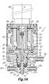
- Figs. 1A to 3 with reference number 1 show a mixing-dispensing head according to an embodiment of this invention.
- Head 1 comprises a casing 10 that defines an interior cavity 11 with an open end 12.
- a pair of components inlet ports 13a, 13b that are open to the exterior communicate with the mentioned interior cavity 11.
- the exterior mouths of said components inlet ports 13a, 13b are designed to receive respective connectors 17a, 17b for the connection of respective conduits 95a, 95b (shown in Fig 5) coming from respective components supply sources (for example, via heaters 7a, 7b shown in Fig 5).
- a solvent inlet port 14 communicates the exterior of the casing 10 with the interior cavity 11 and a pair of solvent outlet ports 15 communicate the interior cavity 11 with the exterior.
- the cited solvent inlet port 14 is designed to receive a connector 18 for connection to a conduit 96 (Fig 5) coming from a solvent supply source.
- valve body 20 Inside the interior cavity 11 of the casing 10, there is a valve body 20, which defines some exterior surfaces and an interior mixing chamber 21 with a dispensing aperture 22 at one end.
- the cited valve body 20 incorporates a pair of components inlet ports 23a, 23b, together with at least one solvent inlet passage 24, which has mouths located on various surfaces of said exterior surfaces and which leads to the mentioned mixing chamber 21.
- the exterior valve body surfaces 20 as well as the interior casing 10 cavity 11 surfaces are shaped, in general, as rotating surfaces with respect to the longitudinal axis E of the head 1, where one of the exterior surfaces of the valve body 20, onto which the components inlet passages 23a, 23b open, is a substantially flat surface 26 (Fig 1B) perpendicular to the longitudinal axis E and facing a substantially flat surface 16 of the interior cavity 11 of the casing 10 onto which the components inlet ports 13a, 13b and the solvent outlet ports 15 open.
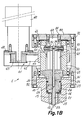
- the valve body is able to rotate within the cavity 11 of the casing 10, between an angular mixing and dispensing position (shown in Figs 1A and 1B), in which the components inlet passages 23a, 23b of the casing valve body 20 communicate with said components inlet ports 13a, 13b of casing 10 and an angular blocking position (shown in Figs 2A and 2B), in which the substantially flat surface 26 of the valve body 20 closes off the components inlet ports 13a, 13b of the casing 10.
- Some seals 91 guarantee leak-tightness between the components inlet ports 13a, 13b and the substantially flat surface 26 of the valve body 20 both in the angular mixing and dispensing position as well as the angular blocking position of the latter.
- inlet and outlet ports may vary depending on requirements and/or applications.
- Some sealing rings 92 are housed inside some annular slots on an exterior surface of the valve body 20, which make contact with a corresponding interior surface of the casing 10. Between both sealing rings 92, the interior surface of the casing 10 presents a slightly recessed area that makes up an annular passage 29 that permanently communicates with the solvent inlet port 14. Therefore, the solvent inlet port 14 can be in any angular position with respect to the components inlet and outlet ports 13a, 13b, although in Figs 1A and 2A they are shown in the same plane for greater drawing simplicity.
- a spindle 30 Inside the mixing chamber 21 of the valve body 20, there is a spindle 30 that can be moved between a retracted position (shown in Figs. 1A and 1B) and an extended position (shown in Figs, 2A and 2B).
- the spindle 30 and the mixing chamber 21 are purposely shaped to define an annular chamber 35 between an exterior surface of the spindle 30 and an interior surface of the mixing chamber 21, which acts as a bridge that permits the flow of fluid from the mentioned solvent inlet passage 24 to the components inlet passages 23a, 23b when the spindle 30 is in the extended position.
- one end 31 of the spindle 30 limits the mentioned dispensing aperture 22 in the mixing chamber 21 at the same time that said solvent inlet passage 24 communicates with said solvent outlet ports 15 through the annular chamber 35 and the components inlet passages 23a, 23b, while in the retracted position, the spindle 30 does not interfere the flow of components from the components inlet passages 23a, 23b directly to the interior of the mixing chamber 21 and the end 31 of the spindle 30 forms a bottom for the mixing chamber 21, which facilitates the exit of the mixture towards the dispensing aperture 22.
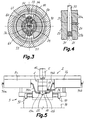
- Fig. 4 shows the detailed construction of the annular chamber 35.
- the cylindrical through hole located in the centre of the valve body 20 has an area of smaller diameter 27a and an area of larger diameter 27b.
- the spindle 30 has an outside diameter that adjusts to the mentioned area of smaller diameter 27a and the end 31 of spindle 30 is wider, with an outside diameter that adjusts to said area of larger diameter 27b.
- the annular chamber 35 is limited by the exterior surface of the spindle, the interior surface of the area of greater diameter 27b, the internal part of the wide end 31 of the spindle and an annular transition wall between the areas of small and greater diameters 27a, 27b.
- the mixing chamber 21 comprises the area of greater diameter 27b, which is free when the spindle is in its retracted position and is limited at the bottom by the spindle end 31, the exterior section of which presents a concave depression, the purpose of which is described below.
- the annular chamber 35 could be formed in several other different ways.
- the through hole in the valve body could have a constant diameter and the spindle could have a section of smaller diameter to define the annular chamber.
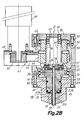
- the head of this invention incorporates some first driving means connected in order to alternately rotate the valve body 20 between the mentioned mixing and dispensing position and said blocking position, and some second driving means connected linearly and alternately translate the spindle 30 along the length of said longitudinal axis E between the mentioned retracted and extended positions. Moreover, the movements of the valve body 20 and the spindle 30 are linked together by means of some kinematic linkage in order to determine that the mixing and dispensing position of the valve body 20 unequivocally corresponds to the extended spindle 30 position and that the blocked position of valve body 20 unequivocally corresponds to the retracted spindle 30 position.
- the first driving means comprise an electric geared motor 40 coupled to rotate, by means of a transmission 41, the valve body 20 and said kinematic linkage means act as the second driving means in order to transmit the rotational movement of the valve body 20 to the spindle 30 and at the same time it converts it into translation movement.
- the geared motor 40 is fixed to a support 48 that is a continuation of a chassis 70 to which the casing 10 is secured by means of screws 71.
- the mentioned transmission 41 consists of a toothed belt 42 coupled to a drive pulley 43 which is fixed to an output shaft on the electric geared motor 40 and to a driven pulley 44 fixed by means of gudgeon pins 46 (Fig. 2B) to a cylindrical sleeve 50, which is installed on said chassis 70 so that it is able to rotate with respect to the longitudinal axis E guided by some bearings 45.
- the valve body 20 is connected to said cylindrical sleeve 50 by gudgeon pins 47, so that the valve body 20 rotates together with the cylindrical sleeve 50.
- a cover 80 which is secured by screws 72 to the chassis 70, closes the end of head 1 opposite the casing 10.
- the kinematic linkage means between valve body 20 movement and that of the spindle 30 consists of a pair of identical, diametrally opposite helicoidal cams 51, inside the cylindrical sleeve 50, and the corresponding cam followers 33 joined to the spindle 30 or, more specifically, to a shaft that is connected to the spindle.
- the mentioned cam followers 33 consist of wheels mounted on a shaft 36 that is transversally fixed to one end of the spindle 30 (better illustrated in Fig. 3), with said wheels arranged to roll over the respective helicoidal surfaces of the cams 51.
- the head 1 also includes some means to prevent the rotation of spindle 30 along the longitudinal axis E, which, however, do not prevent its axial movement, so that the spindle 30 is moved by the action of said helicoidal cam 51 on said cam follower 33 when said cylindrical sleeve 50 is rotated by the geared motor 40.
- These means to prevent the rotation of the spindle 30 consist of a pair of linear guides 61 formed in a stationary part 60 that secured by screws 81 to the mentioned cover 80, which has a fixed position with respect to the casing 10, and the corresponding guide followers 34 joined to the spindle 30 or to said shaft connected to the spindle and coupled to said linear guides 61.
- the mentioned guide followers 34 comprise wheels mounted on the same shaft 36 (better illustrated in Fig. 3) and transversally fixed to one end of the spindle 30, on which the above described cam follower wheels 33 are mounted.
- the mentioned wheels 34 are arranged to roll on the respective flat surfaces of the liner guides 61. Obviously, it is possible to install a single linear guide 61 and follower 34 assembly or more than two, with similar results.
- Some alternative means (not shown) to prevent the rotation of the spindle 30 could consist of, for example, at least a portion of the non-circular section of the spindle 30 inserted into a guide hole in the corresponding non-circular section on the casing 10.
- this alternative embodiment produces greater wear, so that the incorporation of rolling elements or skids to act as guide followers is preferred.
- the geared motor 40 rotates the cylindrical sleeve 50 and the valve body 20, which is fixed to it, to the mixing and dispensing position as shown in Figs. 1A and 1B.
- the spindle 30 moves towards its retracted position, shown in Figs. 1A and 1B.
- the spindle 30 leaves the mixing chamber 21 free and its end 31 provides a bottom wall for the same, while the components inlet passages 23a, 23b of the valve body 20 directly communicate the casing components inlet ports 13a, 13b with the mixing chamber 21.
- the components inlet passages 23a, 23b lead into the mixing chamber 21 in an oblique direction against the exit direction towards the dispensing aperture 22, thus favouring the flow of components into the mixing chamber 21 in a turbulent manner, which assists in the mixing of the components.
- the components inlet passages 23a, 23b lead to the mixing chamber 21 in an area close to the end 31 of the spindle 30 in a retracted position, which facilitates that the oblique flows of the components on entering interfere with the end 31 of the spindle 30 and rebound towards the dispensing aperture 22, additionally favouring the cited turbulent operation.
- the geared motor 40 rotates the cylindrical sleeve 50 and the valve body 20 fixed to the same in an opposite direction to the blocked position as shown in Figs, 2A and 2B.
- the spindle 30 is taken to its extended position that is similarly shown in Figs. 2A and 2B.
- this position which is the head 1 cleaning position
- the substantially flat surface 26 of the valve body 20 closes the mouths of the components inlets ports 13a, 13b and the end 31 of the spindle 30 has ejected any remains of mixture in the mixing chamber 21 via its dispensing aperture 22.
- annular chamber 35 formed between the spindle 30 and the mixing chamber 21 wall establishes a bridge that puts the solvent inlet passage 24 in fluid communication with the components inlet passages 23a, 23b, which permits the cleaning of the mixing chamber wall and the components inlet passages 23a, 23b
- the solvent inlet port 14 is in constant communication with the cited annular passage 29 and this, in turn, is in constant communication with the annular chamber 35 via the solvent inlet passage 24 of the valve body 20.
- the annular chamber 35 only communicates with the components inlet passages 23a, 23b when the spindle 30 is in its extended position (head cleaning position shown in Figs. 2A and 2B), and the components inlet passages 23a, 23b are only in communication with the solvent outlet port 15 when the valve body is in its blocked position (head cleaning position shown in Figs. 2A and 2B).
- the components inlet passages 23a, 23b act as solvent outlet passages together with the component remains, which are finally evacuated via the solvent outlet ports 15.
- the cited concave depression at the end 31 of the spindle 30 operates in the dispensing aperture 22 to force the dripping of the dirty solvent that could slide over the exterior surface of the end of casing 1.
- the components inlet passages 23a, 23b can be positioned directly facing the solvent outlet ports 15, there are other ways to communicate them. In this way, as shown in Fig. 2B, there can be some channels 19 on the substantially flat surface 16 of the interior cavity 11 of the casing 10 in order to communicate the components inlet passages 23a, 23b with the solvent outlet ports 15, although they are not directly facing.
- a solvent outlet port may be constructed in the form of an annular chamber (not shown), consisting of a gap between the valve body 20 and the casing 10 in an area between the substantially flat surface 26 and the end where the dispensing aperture 22 is located , with said annular chamber communicating with a space between the substantially flat surfaces 16, 26 of the casing 10 and the valve body 20 respectively.
- the drive for the valve body 20 and spindle 30 movements is performed by a geared motor 40, the rotation of the valve body 20, together with transmitting and converting the rotation of the valve body 20 in the translation of the spindle 30 by means of the helicoidal cams 51, it is obvious to an expert in the material that the head drive may be obtained using a single motor organ in an inverse manner.
- the second driving means are coupled in order to linearly move the spindle 30 and said kinematic linkage means act as the first driving means in order to transmit the spindle 30 translation movement and convert it into rotational movement of the valve body 20.
- the second driving means comprise a linear drive 49, such as an electric geared motor coupled to a nut and arbour mechanism, or a fluidodynamic piston and cylinder assembly, with an active member linked by means of a coupling 37 to the spindle 30 in order to translate it linearly
- the kinematic linkage means include one or more cam followers 33, connected to the spindle 30 and coupled to some corresponding helicoidal cams 51 formed in a part that is connected to pull the valve body 20.
- Some means are also included here, which could be similar to those described above, to prevent rotation of the spindle 30 when it is moved by the geared motor and while the valve body 20 is rotated by the action of the cam followers on the helicoidal cams.
- the head shown in Fig. 6 is similar to that previously described in relation to Figs. 1A-4.
- FIG. 5 shows a mixer and dispensing unit 2 designed to operate together with a bag handling unit 3 in order to automatically fill said bags with a mixture of the two components.
- the mentioned mixing and injection unit 2 incorporates the mixing-dispensing head 1 according to this invention.
- a heater 7a is installed on one side of the head 1 and connected to a one-component supply source (not shown) via a conduit 94a and some means of flow impulsion for said component.
- Another heater 7b is installed on the other side of the head 1 and connected to another one-component supply source (not shown) via a corresponding conduit 94b and some means of flow impulsion for said component.
- Each of the components inlet ports 13a, 13b for head 1 is connected to the outlet of one of said heaters 7a, 7b via a corresponding conduit 95a, 95b.
- the solvent inlet port 14 for head 1 is connected to a conduit 96 coming from a solvent supply source (not shown).
- one of the components is polyol in a liquid state, and the other is isocyanate, also in a liquid state, and from the mixture of said polyol and said isocyanate in the head mixing chamber 21, a polyurethane PUR foam is produced, which is dispensed through the dispensing aperture 22 in head 1.
- Each of said heaters 7a, 7b is fitted with heating means to heat the corresponding components just before it enters the mixing chamber 21 of the valve body 20 through the respective components inlet ports 13a, 13b and components inlet passages 23a, 23b.
- This replaces the heating hoses that are usually employed in state of the art injection devices to connect the components supply sources to the head, and also to permit a compact design of the mixing and injection unit 2 in conjunction with a relatively reduced head size.
- the bag handling unit 3 includes some means to grip and support a plastic bag 98, for example, by means of automatic clips 97, with an open mouth of the same under the dispensing aperture 22 of head 1 to facilitate bag filling.
- a plastic bag 98 for example, by means of automatic clips 97, with an open mouth of the same under the dispensing aperture 22 of head 1 to facilitate bag filling.
- automatic clips 97 Several bag handling devices are known in the state of the art that could be employed with the mixing and injection unit 2 of this invention.
- the mixing and injection unit 2 together with said bag handling unit 3 form a compact design assembly, which is easily portable, and suitable for table or counter operation.
- the mixing and injection unit 2 can operate in a stand-alone manner or together with the bag handling unit 3, in cooperation with a bag production unit (not shown), of which there are various examples in the state of the art.
- the bags 98 are made from high-density polyethylene film PE-HD.
Landscapes
- Engineering & Computer Science (AREA)
- Mechanical Engineering (AREA)
- Processing And Handling Of Plastics And Other Materials For Molding In General (AREA)
- Mixers Of The Rotary Stirring Type (AREA)
- Multiple-Way Valves (AREA)
- Paper (AREA)
Applications Claiming Priority (1)
| Application Number | Priority Date | Filing Date | Title |
|---|---|---|---|
| ES200401575A ES2222847B1 (es) | 2004-06-29 | 2004-06-29 | Cabezal mezclador dispensador. |
Publications (3)
| Publication Number | Publication Date |
|---|---|
| EP1612019A2 true EP1612019A2 (de) | 2006-01-04 |
| EP1612019A3 EP1612019A3 (de) | 2006-04-19 |
| EP1612019B1 EP1612019B1 (de) | 2007-08-15 |
Family
ID=34354892
Family Applications (1)
| Application Number | Title | Priority Date | Filing Date |
|---|---|---|---|
| EP05380138A Expired - Lifetime EP1612019B1 (de) | 2004-06-29 | 2005-06-29 | Misch- und Ausgabekopf |
Country Status (4)
| Country | Link |
|---|---|
| EP (1) | EP1612019B1 (de) |
| AT (1) | ATE369957T1 (de) |
| DE (1) | DE602005001983D1 (de) |
| ES (2) | ES2222847B1 (de) |
Cited By (4)
| Publication number | Priority date | Publication date | Assignee | Title |
|---|---|---|---|---|
| CN104400928A (zh) * | 2014-11-11 | 2015-03-11 | 浙江师范大学 | 一种可用于原位成型的微量聚合物复合材料循环混炼装置 |
| US20210069945A1 (en) * | 2018-02-23 | 2021-03-11 | Sealed Air Corporation (Us) | Foam-in-bag systems and components thereof |
| WO2022053216A1 (de) * | 2020-09-09 | 2022-03-17 | Kraussmaffei Technologies Gmbh | Vorrichtung und verfahren zum mischen von zumindest zwei chemisch reaktiven kunststoffkomponenten |
| CN118789703A (zh) * | 2024-07-05 | 2024-10-18 | 温州市正峰塑胶有限公司 | 一种多规格热塑性弹性体生产设备 |
Family Cites Families (6)
| Publication number | Priority date | Publication date | Assignee | Title |
|---|---|---|---|---|
| US4440320A (en) * | 1981-11-30 | 1984-04-03 | Wernicke Steven A | Foam dispensing apparatus |
| EP0137250B1 (de) * | 1983-09-03 | 1989-05-17 | MASCHINENFABRIK HENNECKE GmbH | Mehrstoffdüse zum Zusammenführen mindestens zweier fliessfähiger, Kunststoff, insbesondere Schaumstoff bildender Reaktionskomponenten zum Zwecke des Einleitens der Reaktion durch Vermischung und Verfahren zum Betrieb dieser Mehrstoffdüse |
| US5445781A (en) * | 1991-08-28 | 1995-08-29 | Centro Sviluppo Settori Impiego S.R.L. | Process for the injection molding of non-precatalyzed polymerizable resins at high-pressure and flow |
| EP0723843A3 (de) * | 1995-01-27 | 1997-03-26 | Nordson Corp | Abgabekopf für Zweikomponentenschaum mit Abstellvorrichtung |
| US5586724A (en) * | 1995-03-09 | 1996-12-24 | Lockheed Martin Corporation | Tapered plug foam spray apparatus |
| US5996848A (en) * | 1997-07-30 | 1999-12-07 | Carpenter Co. | Dispensing system, components of a dispensing system, and method of manufacturing, operating and servicing a dispensing system and components thereof |
-
2004
- 2004-06-29 ES ES200401575A patent/ES2222847B1/es not_active Expired - Fee Related
-
2005
- 2005-06-29 ES ES05380138T patent/ES2294665T3/es not_active Expired - Lifetime
- 2005-06-29 AT AT05380138T patent/ATE369957T1/de not_active IP Right Cessation
- 2005-06-29 EP EP05380138A patent/EP1612019B1/de not_active Expired - Lifetime
- 2005-06-29 DE DE602005001983T patent/DE602005001983D1/de not_active Expired - Lifetime
Cited By (7)
| Publication number | Priority date | Publication date | Assignee | Title |
|---|---|---|---|---|
| CN104400928A (zh) * | 2014-11-11 | 2015-03-11 | 浙江师范大学 | 一种可用于原位成型的微量聚合物复合材料循环混炼装置 |
| CN104400928B (zh) * | 2014-11-11 | 2017-01-18 | 浙江师范大学 | 一种可用于原位成型的微量聚合物复合材料循环混炼装置 |
| US20210069945A1 (en) * | 2018-02-23 | 2021-03-11 | Sealed Air Corporation (Us) | Foam-in-bag systems and components thereof |
| US12030221B2 (en) * | 2018-02-23 | 2024-07-09 | Sealed Air Corporation (Us) | Foam-in-bag systems and components thereof |
| WO2022053216A1 (de) * | 2020-09-09 | 2022-03-17 | Kraussmaffei Technologies Gmbh | Vorrichtung und verfahren zum mischen von zumindest zwei chemisch reaktiven kunststoffkomponenten |
| CN118789703A (zh) * | 2024-07-05 | 2024-10-18 | 温州市正峰塑胶有限公司 | 一种多规格热塑性弹性体生产设备 |
| CN118789703B (zh) * | 2024-07-05 | 2024-11-29 | 温州市正峰塑胶有限公司 | 一种多规格热塑性弹性体生产设备 |
Also Published As
| Publication number | Publication date |
|---|---|
| DE602005001983D1 (de) | 2007-09-27 |
| EP1612019B1 (de) | 2007-08-15 |
| ATE369957T1 (de) | 2007-09-15 |
| ES2294665T3 (es) | 2008-04-01 |
| EP1612019A3 (de) | 2006-04-19 |
| ES2222847B1 (es) | 2006-03-16 |
| ES2222847A1 (es) | 2005-02-01 |
Similar Documents
| Publication | Publication Date | Title |
|---|---|---|
| US6105822A (en) | Device and method for mixing and dispensing two flowable materials | |
| US4400147A (en) | Flushable rotary gear pump | |
| KR101819994B1 (ko) | 유체 제품을 송출하기 위한 장치 및 관련 방법 | |
| RU2427432C2 (ru) | Устройство для нанесения покрытий с дозировочным устройством | |
| US6612821B1 (en) | Pump, in particular gear pump including ceramic gears and seal | |
| US20040208750A1 (en) | Fluid discharge pumping apparatus | |
| US4606942A (en) | Spray coating apparatus | |
| KR101116711B1 (ko) | 액재 토출 장치 | |
| EP1612019B1 (de) | Misch- und Ausgabekopf | |
| US5829647A (en) | Metering gearhead dispensing apparatus having selectively positionable gear pumps | |
| KR20170135285A (ko) | 유체를 복수 개의 유로로 선택적으로 배분하는 유로 전환 밸브 | |
| US5547110A (en) | Metering device for fluids | |
| CN101324279A (zh) | 旋转式流体分配阀 | |
| AU2003215875A1 (en) | Method and apparatus for the production of mechanical power from hydraulic energy | |
| JP2009216164A (ja) | ロータリ制御弁 | |
| CN1706567B (zh) | 清洗装置及包含该装置的阀门设备 | |
| CN101331321B (zh) | 热熔胶计量站 | |
| KR101133192B1 (ko) | 특히 탱크 세정장치에 결합하여 사용하는 구동장치 | |
| CN117405298A (zh) | 一种麻醉呼吸管路气密性检测装置 | |
| KR100514942B1 (ko) | 아이스크림 나선형 공급장치 | |
| CN220126740U (zh) | 粘合剂分配系统 | |
| JP3577401B2 (ja) | 複数計量液の同時分配装置 | |
| KR20070085241A (ko) | 유체의 화학적/물리적 처리를 위한 회전식 분배기 밸브 | |
| RU2020237C1 (ru) | Устройство для подачи жидкости для форсуночного орошения зубков, в частности, холодной воды | |
| HU193991B (en) | Multiple-purpose chemical industrial apparatus |
Legal Events
| Date | Code | Title | Description |
|---|---|---|---|
| PUAI | Public reference made under article 153(3) epc to a published international application that has entered the european phase |
Free format text: ORIGINAL CODE: 0009012 |
|
| AK | Designated contracting states |
Kind code of ref document: A2 Designated state(s): AT BE BG CH CY CZ DE DK EE ES FI FR GB GR HU IE IS IT LI LT LU MC NL PL PT RO SE SI SK TR |
|
| AX | Request for extension of the european patent |
Extension state: AL BA HR LV MK YU |
|
| PUAL | Search report despatched |
Free format text: ORIGINAL CODE: 0009013 |
|
| AK | Designated contracting states |
Kind code of ref document: A3 Designated state(s): AT BE BG CH CY CZ DE DK EE ES FI FR GB GR HU IE IS IT LI LT LU MC NL PL PT RO SE SI SK TR |
|
| AX | Request for extension of the european patent |
Extension state: AL BA HR LV MK YU |
|
| 17P | Request for examination filed |
Effective date: 20061016 |
|
| AKX | Designation fees paid |
Designated state(s): AT BE BG CH CY CZ DE DK EE ES FI FR GB GR HU IE IS IT LI LT LU MC NL PL PT RO SE SI SK TR |
|
| GRAP | Despatch of communication of intention to grant a patent |
Free format text: ORIGINAL CODE: EPIDOSNIGR1 |
|
| GRAS | Grant fee paid |
Free format text: ORIGINAL CODE: EPIDOSNIGR3 |
|
| GRAA | (expected) grant |
Free format text: ORIGINAL CODE: 0009210 |
|
| AK | Designated contracting states |
Kind code of ref document: B1 Designated state(s): AT BE BG CH CY CZ DE DK EE ES FI FR GB GR HU IE IS IT LI LT LU MC NL PL PT RO SE SI SK TR |
|
| REG | Reference to a national code |
Ref country code: GB Ref legal event code: FG4D |
|
| REG | Reference to a national code |
Ref country code: CH Ref legal event code: EP |
|
| REG | Reference to a national code |
Ref country code: IE Ref legal event code: FG4D |
|
| REF | Corresponds to: |
Ref document number: 602005001983 Country of ref document: DE Date of ref document: 20070927 Kind code of ref document: P |
|
| PG25 | Lapsed in a contracting state [announced via postgrant information from national office to epo] |
Ref country code: NL Free format text: LAPSE BECAUSE OF FAILURE TO SUBMIT A TRANSLATION OF THE DESCRIPTION OR TO PAY THE FEE WITHIN THE PRESCRIBED TIME-LIMIT Effective date: 20070815 Ref country code: IS Free format text: LAPSE BECAUSE OF FAILURE TO SUBMIT A TRANSLATION OF THE DESCRIPTION OR TO PAY THE FEE WITHIN THE PRESCRIBED TIME-LIMIT Effective date: 20071215 Ref country code: BG Free format text: LAPSE BECAUSE OF FAILURE TO SUBMIT A TRANSLATION OF THE DESCRIPTION OR TO PAY THE FEE WITHIN THE PRESCRIBED TIME-LIMIT Effective date: 20071115 Ref country code: LT Free format text: LAPSE BECAUSE OF FAILURE TO SUBMIT A TRANSLATION OF THE DESCRIPTION OR TO PAY THE FEE WITHIN THE PRESCRIBED TIME-LIMIT Effective date: 20070815 Ref country code: FI Free format text: LAPSE BECAUSE OF FAILURE TO SUBMIT A TRANSLATION OF THE DESCRIPTION OR TO PAY THE FEE WITHIN THE PRESCRIBED TIME-LIMIT Effective date: 20070815 |
|
| NLV1 | Nl: lapsed or annulled due to failure to fulfill the requirements of art. 29p and 29m of the patents act | ||
| PG25 | Lapsed in a contracting state [announced via postgrant information from national office to epo] |
Ref country code: CH Free format text: LAPSE BECAUSE OF FAILURE TO SUBMIT A TRANSLATION OF THE DESCRIPTION OR TO PAY THE FEE WITHIN THE PRESCRIBED TIME-LIMIT Effective date: 20070815 Ref country code: PL Free format text: LAPSE BECAUSE OF FAILURE TO SUBMIT A TRANSLATION OF THE DESCRIPTION OR TO PAY THE FEE WITHIN THE PRESCRIBED TIME-LIMIT Effective date: 20070815 Ref country code: LI Free format text: LAPSE BECAUSE OF FAILURE TO SUBMIT A TRANSLATION OF THE DESCRIPTION OR TO PAY THE FEE WITHIN THE PRESCRIBED TIME-LIMIT Effective date: 20070815 Ref country code: AT Free format text: LAPSE BECAUSE OF FAILURE TO SUBMIT A TRANSLATION OF THE DESCRIPTION OR TO PAY THE FEE WITHIN THE PRESCRIBED TIME-LIMIT Effective date: 20070815 |
|
| REG | Reference to a national code |
Ref country code: CH Ref legal event code: PL |
|
| PG25 | Lapsed in a contracting state [announced via postgrant information from national office to epo] |
Ref country code: BE Free format text: LAPSE BECAUSE OF FAILURE TO SUBMIT A TRANSLATION OF THE DESCRIPTION OR TO PAY THE FEE WITHIN THE PRESCRIBED TIME-LIMIT Effective date: 20070815 |
|
| REG | Reference to a national code |
Ref country code: ES Ref legal event code: FG2A Ref document number: 2294665 Country of ref document: ES Kind code of ref document: T3 |
|
| EN | Fr: translation not filed | ||
| PG25 | Lapsed in a contracting state [announced via postgrant information from national office to epo] |
Ref country code: GR Free format text: LAPSE BECAUSE OF FAILURE TO SUBMIT A TRANSLATION OF THE DESCRIPTION OR TO PAY THE FEE WITHIN THE PRESCRIBED TIME-LIMIT Effective date: 20071116 Ref country code: DK Free format text: LAPSE BECAUSE OF FAILURE TO SUBMIT A TRANSLATION OF THE DESCRIPTION OR TO PAY THE FEE WITHIN THE PRESCRIBED TIME-LIMIT Effective date: 20070815 |
|
| PG25 | Lapsed in a contracting state [announced via postgrant information from national office to epo] |
Ref country code: CZ Free format text: LAPSE BECAUSE OF FAILURE TO SUBMIT A TRANSLATION OF THE DESCRIPTION OR TO PAY THE FEE WITHIN THE PRESCRIBED TIME-LIMIT Effective date: 20070815 Ref country code: SK Free format text: LAPSE BECAUSE OF FAILURE TO SUBMIT A TRANSLATION OF THE DESCRIPTION OR TO PAY THE FEE WITHIN THE PRESCRIBED TIME-LIMIT Effective date: 20070815 Ref country code: PT Free format text: LAPSE BECAUSE OF FAILURE TO SUBMIT A TRANSLATION OF THE DESCRIPTION OR TO PAY THE FEE WITHIN THE PRESCRIBED TIME-LIMIT Effective date: 20080115 |
|
| PLBE | No opposition filed within time limit |
Free format text: ORIGINAL CODE: 0009261 |
|
| STAA | Information on the status of an ep patent application or granted ep patent |
Free format text: STATUS: NO OPPOSITION FILED WITHIN TIME LIMIT |
|
| PG25 | Lapsed in a contracting state [announced via postgrant information from national office to epo] |
Ref country code: RO Free format text: LAPSE BECAUSE OF FAILURE TO SUBMIT A TRANSLATION OF THE DESCRIPTION OR TO PAY THE FEE WITHIN THE PRESCRIBED TIME-LIMIT Effective date: 20070815 Ref country code: SE Free format text: LAPSE BECAUSE OF FAILURE TO SUBMIT A TRANSLATION OF THE DESCRIPTION OR TO PAY THE FEE WITHIN THE PRESCRIBED TIME-LIMIT Effective date: 20071115 |
|
| 26N | No opposition filed |
Effective date: 20080516 |
|
| PG25 | Lapsed in a contracting state [announced via postgrant information from national office to epo] |
Ref country code: DE Free format text: LAPSE BECAUSE OF FAILURE TO SUBMIT A TRANSLATION OF THE DESCRIPTION OR TO PAY THE FEE WITHIN THE PRESCRIBED TIME-LIMIT Effective date: 20071116 |
|
| PGFP | Annual fee paid to national office [announced via postgrant information from national office to epo] |
Ref country code: ES Payment date: 20080619 Year of fee payment: 4 |
|
| PG25 | Lapsed in a contracting state [announced via postgrant information from national office to epo] |
Ref country code: MC Free format text: LAPSE BECAUSE OF NON-PAYMENT OF DUE FEES Effective date: 20080630 |
|
| PG25 | Lapsed in a contracting state [announced via postgrant information from national office to epo] |
Ref country code: EE Free format text: LAPSE BECAUSE OF FAILURE TO SUBMIT A TRANSLATION OF THE DESCRIPTION OR TO PAY THE FEE WITHIN THE PRESCRIBED TIME-LIMIT Effective date: 20070815 Ref country code: IE Free format text: LAPSE BECAUSE OF NON-PAYMENT OF DUE FEES Effective date: 20080630 |
|
| PG25 | Lapsed in a contracting state [announced via postgrant information from national office to epo] |
Ref country code: SI Free format text: LAPSE BECAUSE OF FAILURE TO SUBMIT A TRANSLATION OF THE DESCRIPTION OR TO PAY THE FEE WITHIN THE PRESCRIBED TIME-LIMIT Effective date: 20070815 |
|
| PG25 | Lapsed in a contracting state [announced via postgrant information from national office to epo] |
Ref country code: CY Free format text: LAPSE BECAUSE OF FAILURE TO SUBMIT A TRANSLATION OF THE DESCRIPTION OR TO PAY THE FEE WITHIN THE PRESCRIBED TIME-LIMIT Effective date: 20070815 |
|
| GBPC | Gb: european patent ceased through non-payment of renewal fee |
Effective date: 20090629 |
|
| PG25 | Lapsed in a contracting state [announced via postgrant information from national office to epo] |
Ref country code: GB Free format text: LAPSE BECAUSE OF NON-PAYMENT OF DUE FEES Effective date: 20090629 |
|
| PG25 | Lapsed in a contracting state [announced via postgrant information from national office to epo] |
Ref country code: HU Free format text: LAPSE BECAUSE OF FAILURE TO SUBMIT A TRANSLATION OF THE DESCRIPTION OR TO PAY THE FEE WITHIN THE PRESCRIBED TIME-LIMIT Effective date: 20080216 Ref country code: LU Free format text: LAPSE BECAUSE OF NON-PAYMENT OF DUE FEES Effective date: 20080629 |
|
| REG | Reference to a national code |
Ref country code: ES Ref legal event code: FD2A Effective date: 20090630 |
|
| PG25 | Lapsed in a contracting state [announced via postgrant information from national office to epo] |
Ref country code: TR Free format text: LAPSE BECAUSE OF FAILURE TO SUBMIT A TRANSLATION OF THE DESCRIPTION OR TO PAY THE FEE WITHIN THE PRESCRIBED TIME-LIMIT Effective date: 20070815 |
|
| PG25 | Lapsed in a contracting state [announced via postgrant information from national office to epo] |
Ref country code: ES Free format text: LAPSE BECAUSE OF NON-PAYMENT OF DUE FEES Effective date: 20090630 |
|
| PG25 | Lapsed in a contracting state [announced via postgrant information from national office to epo] |
Ref country code: IT Free format text: LAPSE BECAUSE OF NON-PAYMENT OF DUE FEES Effective date: 20080630 |
|
| PG25 | Lapsed in a contracting state [announced via postgrant information from national office to epo] |
Ref country code: FR Free format text: LAPSE BECAUSE OF FAILURE TO SUBMIT A TRANSLATION OF THE DESCRIPTION OR TO PAY THE FEE WITHIN THE PRESCRIBED TIME-LIMIT Effective date: 20080411 |