EP1611948A1 - Polymerization reactors with a by-pass line - Google Patents
Polymerization reactors with a by-pass line Download PDFInfo
- Publication number
- EP1611948A1 EP1611948A1 EP04103110A EP04103110A EP1611948A1 EP 1611948 A1 EP1611948 A1 EP 1611948A1 EP 04103110 A EP04103110 A EP 04103110A EP 04103110 A EP04103110 A EP 04103110A EP 1611948 A1 EP1611948 A1 EP 1611948A1
- Authority
- EP
- European Patent Office
- Prior art keywords
- reactor
- pass line
- loop reactor
- slurry loop
- slurry
- Prior art date
- Legal status (The legal status is an assumption and is not a legal conclusion. Google has not performed a legal analysis and makes no representation as to the accuracy of the status listed.)
- Withdrawn
Links
- 238000006116 polymerization reaction Methods 0.000 title description 4
- 239000002002 slurry Substances 0.000 claims abstract description 26
- 229920000642 polymer Polymers 0.000 claims abstract description 19
- 150000001336 alkenes Chemical class 0.000 claims description 11
- JRZJOMJEPLMPRA-UHFFFAOYSA-N olefin Natural products CCCCCCCC=C JRZJOMJEPLMPRA-UHFFFAOYSA-N 0.000 claims description 9
- 239000007787 solid Substances 0.000 claims description 6
- VGGSQFUCUMXWEO-UHFFFAOYSA-N Ethene Chemical compound C=C VGGSQFUCUMXWEO-UHFFFAOYSA-N 0.000 claims description 3
- 239000005977 Ethylene Substances 0.000 claims description 3
- 239000002245 particle Substances 0.000 claims description 3
- QQONPFPTGQHPMA-UHFFFAOYSA-N propylene Natural products CC=C QQONPFPTGQHPMA-UHFFFAOYSA-N 0.000 claims description 2
- 125000004805 propylene group Chemical group [H]C([H])([H])C([H])([*:1])C([H])([H])[*:2] 0.000 claims description 2
- 239000007788 liquid Substances 0.000 description 9
- 238000000034 method Methods 0.000 description 6
- 238000000926 separation method Methods 0.000 description 6
- 239000003054 catalyst Substances 0.000 description 4
- 239000000463 material Substances 0.000 description 4
- 239000000178 monomer Substances 0.000 description 4
- 239000003085 diluting agent Substances 0.000 description 3
- 238000004062 sedimentation Methods 0.000 description 3
- 230000003247 decreasing effect Effects 0.000 description 2
- 229920001903 high density polyethylene Polymers 0.000 description 2
- 239000004700 high-density polyethylene Substances 0.000 description 2
- 238000000746 purification Methods 0.000 description 2
- 230000001133 acceleration Effects 0.000 description 1
- 238000012644 addition polymerization Methods 0.000 description 1
- 238000004364 calculation method Methods 0.000 description 1
- 238000006243 chemical reaction Methods 0.000 description 1
- 238000011109 contamination Methods 0.000 description 1
- 238000010924 continuous production Methods 0.000 description 1
- 238000009826 distribution Methods 0.000 description 1
- 238000005516 engineering process Methods 0.000 description 1
- 239000012530 fluid Substances 0.000 description 1
- 230000005484 gravity Effects 0.000 description 1
- 239000003701 inert diluent Substances 0.000 description 1
- 238000004519 manufacturing process Methods 0.000 description 1
- 239000000203 mixture Substances 0.000 description 1
- 229920000098 polyolefin Polymers 0.000 description 1
- 238000004064 recycling Methods 0.000 description 1
- 239000002904 solvent Substances 0.000 description 1
- 239000004711 α-olefin Substances 0.000 description 1
Images

Classifications
-
- B—PERFORMING OPERATIONS; TRANSPORTING
- B01—PHYSICAL OR CHEMICAL PROCESSES OR APPARATUS IN GENERAL
- B01J—CHEMICAL OR PHYSICAL PROCESSES, e.g. CATALYSIS OR COLLOID CHEMISTRY; THEIR RELEVANT APPARATUS
- B01J19/00—Chemical, physical or physico-chemical processes in general; Their relevant apparatus
- B01J19/24—Stationary reactors without moving elements inside
-
- C—CHEMISTRY; METALLURGY
- C08—ORGANIC MACROMOLECULAR COMPOUNDS; THEIR PREPARATION OR CHEMICAL WORKING-UP; COMPOSITIONS BASED THEREON
- C08F—MACROMOLECULAR COMPOUNDS OBTAINED BY REACTIONS ONLY INVOLVING CARBON-TO-CARBON UNSATURATED BONDS
- C08F10/00—Homopolymers and copolymers of unsaturated aliphatic hydrocarbons having only one carbon-to-carbon double bond
-
- B—PERFORMING OPERATIONS; TRANSPORTING
- B01—PHYSICAL OR CHEMICAL PROCESSES OR APPARATUS IN GENERAL
- B01J—CHEMICAL OR PHYSICAL PROCESSES, e.g. CATALYSIS OR COLLOID CHEMISTRY; THEIR RELEVANT APPARATUS
- B01J19/00—Chemical, physical or physico-chemical processes in general; Their relevant apparatus
- B01J19/18—Stationary reactors having moving elements inside
-
- B—PERFORMING OPERATIONS; TRANSPORTING
- B01—PHYSICAL OR CHEMICAL PROCESSES OR APPARATUS IN GENERAL
- B01J—CHEMICAL OR PHYSICAL PROCESSES, e.g. CATALYSIS OR COLLOID CHEMISTRY; THEIR RELEVANT APPARATUS
- B01J19/00—Chemical, physical or physico-chemical processes in general; Their relevant apparatus
- B01J19/18—Stationary reactors having moving elements inside
- B01J19/1812—Tubular reactors
- B01J19/1837—Loop-type reactors
-
- B—PERFORMING OPERATIONS; TRANSPORTING
- B01—PHYSICAL OR CHEMICAL PROCESSES OR APPARATUS IN GENERAL
- B01J—CHEMICAL OR PHYSICAL PROCESSES, e.g. CATALYSIS OR COLLOID CHEMISTRY; THEIR RELEVANT APPARATUS
- B01J19/00—Chemical, physical or physico-chemical processes in general; Their relevant apparatus
- B01J19/18—Stationary reactors having moving elements inside
- B01J19/1868—Stationary reactors having moving elements inside resulting in a loop-type movement
- B01J19/1881—Stationary reactors having moving elements inside resulting in a loop-type movement externally, i.e. the mixture leaving the vessel and subsequently re-entering it
-
- B—PERFORMING OPERATIONS; TRANSPORTING
- B01—PHYSICAL OR CHEMICAL PROCESSES OR APPARATUS IN GENERAL
- B01J—CHEMICAL OR PHYSICAL PROCESSES, e.g. CATALYSIS OR COLLOID CHEMISTRY; THEIR RELEVANT APPARATUS
- B01J8/00—Chemical or physical processes in general, conducted in the presence of fluids and solid particles; Apparatus for such processes
-
- B—PERFORMING OPERATIONS; TRANSPORTING
- B01—PHYSICAL OR CHEMICAL PROCESSES OR APPARATUS IN GENERAL
- B01J—CHEMICAL OR PHYSICAL PROCESSES, e.g. CATALYSIS OR COLLOID CHEMISTRY; THEIR RELEVANT APPARATUS
- B01J8/00—Chemical or physical processes in general, conducted in the presence of fluids and solid particles; Apparatus for such processes
- B01J8/005—Separating solid material from the gas/liquid stream
- B01J8/007—Separating solid material from the gas/liquid stream by sedimentation
-
- B—PERFORMING OPERATIONS; TRANSPORTING
- B01—PHYSICAL OR CHEMICAL PROCESSES OR APPARATUS IN GENERAL
- B01J—CHEMICAL OR PHYSICAL PROCESSES, e.g. CATALYSIS OR COLLOID CHEMISTRY; THEIR RELEVANT APPARATUS
- B01J8/00—Chemical or physical processes in general, conducted in the presence of fluids and solid particles; Apparatus for such processes
- B01J8/18—Chemical or physical processes in general, conducted in the presence of fluids and solid particles; Apparatus for such processes with fluidised particles
- B01J8/20—Chemical or physical processes in general, conducted in the presence of fluids and solid particles; Apparatus for such processes with fluidised particles with liquid as a fluidising medium
- B01J8/22—Chemical or physical processes in general, conducted in the presence of fluids and solid particles; Apparatus for such processes with fluidised particles with liquid as a fluidising medium gas being introduced into the liquid
-
- B—PERFORMING OPERATIONS; TRANSPORTING
- B01—PHYSICAL OR CHEMICAL PROCESSES OR APPARATUS IN GENERAL
- B01J—CHEMICAL OR PHYSICAL PROCESSES, e.g. CATALYSIS OR COLLOID CHEMISTRY; THEIR RELEVANT APPARATUS
- B01J2219/00—Chemical, physical or physico-chemical processes in general; Their relevant apparatus
- B01J2219/00002—Chemical plants
- B01J2219/00018—Construction aspects
- B01J2219/00024—Revamping, retrofitting or modernisation of existing plants
-
- B—PERFORMING OPERATIONS; TRANSPORTING
- B01—PHYSICAL OR CHEMICAL PROCESSES OR APPARATUS IN GENERAL
- B01J—CHEMICAL OR PHYSICAL PROCESSES, e.g. CATALYSIS OR COLLOID CHEMISTRY; THEIR RELEVANT APPARATUS
- B01J2219/00—Chemical, physical or physico-chemical processes in general; Their relevant apparatus
- B01J2219/00002—Chemical plants
- B01J2219/00027—Process aspects
- B01J2219/0004—Processes in series
-
- B—PERFORMING OPERATIONS; TRANSPORTING
- B01—PHYSICAL OR CHEMICAL PROCESSES OR APPARATUS IN GENERAL
- B01J—CHEMICAL OR PHYSICAL PROCESSES, e.g. CATALYSIS OR COLLOID CHEMISTRY; THEIR RELEVANT APPARATUS
- B01J2219/00—Chemical, physical or physico-chemical processes in general; Their relevant apparatus
- B01J2219/00049—Controlling or regulating processes
- B01J2219/00051—Controlling the temperature
- B01J2219/00074—Controlling the temperature by indirect heating or cooling employing heat exchange fluids
- B01J2219/00087—Controlling the temperature by indirect heating or cooling employing heat exchange fluids with heat exchange elements outside the reactor
- B01J2219/00094—Jackets
-
- B—PERFORMING OPERATIONS; TRANSPORTING
- B01—PHYSICAL OR CHEMICAL PROCESSES OR APPARATUS IN GENERAL
- B01J—CHEMICAL OR PHYSICAL PROCESSES, e.g. CATALYSIS OR COLLOID CHEMISTRY; THEIR RELEVANT APPARATUS
- B01J2219/00—Chemical, physical or physico-chemical processes in general; Their relevant apparatus
- B01J2219/00049—Controlling or regulating processes
- B01J2219/00164—Controlling or regulating processes controlling the flow
- B01J2219/00166—Controlling or regulating processes controlling the flow controlling the residence time inside the reactor vessel
-
- B—PERFORMING OPERATIONS; TRANSPORTING
- B01—PHYSICAL OR CHEMICAL PROCESSES OR APPARATUS IN GENERAL
- B01J—CHEMICAL OR PHYSICAL PROCESSES, e.g. CATALYSIS OR COLLOID CHEMISTRY; THEIR RELEVANT APPARATUS
- B01J2219/00—Chemical, physical or physico-chemical processes in general; Their relevant apparatus
- B01J2219/00049—Controlling or regulating processes
- B01J2219/00184—Controlling or regulating processes controlling the weight of reactants in the reactor vessel
-
- B—PERFORMING OPERATIONS; TRANSPORTING
- B01—PHYSICAL OR CHEMICAL PROCESSES OR APPARATUS IN GENERAL
- B01J—CHEMICAL OR PHYSICAL PROCESSES, e.g. CATALYSIS OR COLLOID CHEMISTRY; THEIR RELEVANT APPARATUS
- B01J2219/00—Chemical, physical or physico-chemical processes in general; Their relevant apparatus
- B01J2219/00049—Controlling or regulating processes
- B01J2219/00245—Avoiding undesirable reactions or side-effects
- B01J2219/00254—Formation of unwanted polymer, such as "pop-corn"
Definitions
- This invention is related to the field of olefin polymerisation in double loop reactors.
- High density polyethylene was first produced by addition polymerization carried out in a liquid that was a solvent for the resulting polymer. That method was rapidly replaced by polymerisation under slurry conditions according to Ziegler or Phillips. More specifically slurry polymerisation was carried out continuously in a pipe loop reactor. A polymerization effluent is formed which is a slurry of particulate polymer solids suspended in a liquid medium, ordinarily the reaction diluent and unreacted monomer (see for Example US-A-2,285,721).
- Settling legs are typically required to improve the polymer concentration in the slurry extracted from the reactor; they present however several problems as they impose a batch technique onto a continuous process.
- EP-A-0,891,990 and US-A-6,204,344 disclose two methods for decreasing the discontinuous behaviour of the reactor and thereby for increasing the solids concentration.
- One method consists in replacing the discontinuous operation of the settling legs by a continuous retrieval of enriched slurry.
- Another method consists in using a more aggressive circulation pump.
- EP-A-1410843 has disclosed a slurry loop reactor comprising on one of the loops a by-pass line connecting two points of the same loop by an alternate route having a different transit time than that of the main route for improving the homogeneity of the circulating slurry.
- the double loop systems are quite desirable as they offer the possibility to prepare highly tailored polyolefins by providing different polymerising conditions in each reactor. It is however often difficult to find suitable space to build these double loop reactors as in the current configuration they need to be close to one another in order to insure adequate transfer of growing polymer from one loop to the other.
- the velocity of the material circulating in the transfer line is of less than 1 m/s: these lines must therefore be very short in order to avoid sedimentation and clogging due to the polymerisation of residual monomers.
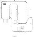
- Figure 1 represents the double loop reactor configuration of the present invention wherein the two reactors are connected by a by-pass line.
- Figure 2 represents the by-pass line connecting two points of the second reactor and collecting growing polymer from the settling legs of the first reactor.
- the present invention discloses a slurry loop reactor comprising at least two loop reactors connected in series and a by-pass line (11), as represented in Figure 1, for connecting two points of the same loop reactor (12) and (13) by an alternate route having a different transit time than that of the main route, said by-pass line (11) also collecting the growing polymer exiting the first loop reactor (1) at exit points (14) and sending said growing polymer to an entry point (13) in the second reactor (2).
- the growing polymer exiting the first reactor can be collected either by continuous discharge or by settling legs technology.
- settling legs are used.
- the entry point (13) into the second reactor is preferably located up-flow of the circulating pump, where the pressure is low.
- the by-pass may be jacketed.
- the velocity of the material circulating in the by-pass must be sufficient to avoid sedimentation and possibly clogging: it must be of at least 3 m/s.
- the design of the by-pass line is such that the pressure difference between the two ends of the by-pass line (12) and (13) can provide the minimum velocity of about 3 m/s required to obtain adequate flow of material and to avoid blockage.
- pumps may be added to increase velocity in the by-pass line. It is however preferred to rely only on the pressure difference as any added device leads to added difficulties.
- the velocity in the by-pass is preferably of at least 4 m/s, more preferably of at least 5.5 m/s and most preferably of at least 7 m/s.
- the entry point (12) of the by-pass line is located higher than its exit point (13) in order to give the by-pass line a minimum slope of at least 7 degrees, preferably of about 9 degrees.
- the by-pass line carries a fraction of the slurry of from 0.5 to 50 % of the total flow rate, preferably of 1 to 25 % and more preferably 1 to 15 % of the total flow rate.
- the flow time through the by-pass line is different from the time necessary to travel through the main loop as the routes have different lengths. This difference in travel time results in longitudinal mixing that improves the homogeneity of the slurry within the reactor.
- the angles at flow separation and at flow reunion can be the same or different.
- the slurry is collected and re-injected in the main loop at an angle of from 1 to 90 degrees, preferably at an angle of from 30 to 60 degrees and more preferably at an angle of about 45 degrees.
- the diameter of the by-pass is less than that of the main loop and the ratio DB/DL of the by-pass diameter DB to the loop diameter DL is of from 1:12 to 1:2, preferably of from 1:6 to 1:3.
- the diameter of the by-pass line is of from 12 cm to 30 cm, preferably of 15.24 cm (6 inches) to 20.32 cm (8 inches).
- the bends in the by-pass line are preferably long-radius bends: typically they have a radius of curvature that is equal to at least 10 times the diameter of the by-pass line.
- the distance between the two loops to be connected can be of up to 30 m, preferably of up to 20 m, more preferably of up to 15 m, when operated solely by the pressure difference between the entry point and the exit point of the by-pass line.
- the reactor can be operated with any catalyst system known in the art. It can be used for the homo- or co-polymerisation of olefins.
- the olefin is an alpha-olefin, more preferably ethylene or propylene, and most preferably ethylene.
- Design D2 was the same as D1 except that the length of the by-pass line was equal to 15 m.
- Design D3 was the same as D1 except that the diameter of the by-pass line was equal to 20.32 cm (8 inches).
- Design D4 was the same as D2 except that the diameter of the by-pass line was equal to 20.32 cm (8 inches).
- Design D5 was the same as D1 except that the angles of flow separation and of flow reunion were both set to 90°.
- Design D6 was the same as D2 except that the angles of flow separation and of flow reunion were both set to 90°.
- the velocity at point A located between the flow reunion point (13) and the flow separation point (12) and representing 100 % of the flow was selected to be about 9.3 m/s.
- the velocity in the by-pass line is well above the velocity of less than 1 m/s existing in currently available transfer lines and well above the minimum speed in horizontal lines of 3 m/s as calculated by Durand equation, necessary to avoid sedimentation.
Landscapes
- Chemical & Material Sciences (AREA)
- Organic Chemistry (AREA)
- Chemical Kinetics & Catalysis (AREA)
- Health & Medical Sciences (AREA)
- Medicinal Chemistry (AREA)
- Polymers & Plastics (AREA)
- Engineering & Computer Science (AREA)
- Combustion & Propulsion (AREA)
- Polymerisation Methods In General (AREA)
- Addition Polymer Or Copolymer, Post-Treatments, Or Chemical Modifications (AREA)
- Physical Or Chemical Processes And Apparatus (AREA)
- Polyesters Or Polycarbonates (AREA)
Abstract
The present invention discloses a slurry loop reactor having at least two loops (1,2) and comprising a by-pass line (11) connecting two points (12,13) of the same loop reactor by an alternate route having a different transit time than that of the main route, said by-pass line also collecting the growing polymer of a first loop reactor (1) and sending said growing polymer to an entry point (13) in a second reactor (2).
Description
- This invention is related to the field of olefin polymerisation in double loop reactors.
- High density polyethylene (HDPE) was first produced by addition polymerization carried out in a liquid that was a solvent for the resulting polymer. That method was rapidly replaced by polymerisation under slurry conditions according to Ziegler or Phillips. More specifically slurry polymerisation was carried out continuously in a pipe loop reactor. A polymerization effluent is formed which is a slurry of particulate polymer solids suspended in a liquid medium, ordinarily the reaction diluent and unreacted monomer (see for Example US-A-2,285,721). It is desirable to separate the polymer and the liquid medium comprising an inert diluent and unreacted monomers without exposing the liquid medium to contamination so that said liquid medium can be recycled to the polymerization zone with minimal or no purification. As described in US-A-3,152,872, a slurry of polymer and the liquid medium is collected in one or more settling legs of the slurry loop reactor from which the slurry is periodically discharged to a flash chamber thus operating in a batch-wise manner. The mixture is flashed in order to remove the liquid medium from the polymer. It is afterwards necessary to recompress the vaporized polymerization diluent to condense it to a liquid form prior to recycling it as liquid diluent to the polymerisation zone after purification if necessary.
- Settling legs are typically required to improve the polymer concentration in the slurry extracted from the reactor; they present however several problems as they impose a batch technique onto a continuous process.
- EP-A-0,891,990 and US-A-6,204,344 disclose two methods for decreasing the discontinuous behaviour of the reactor and thereby for increasing the solids concentration. One method consists in replacing the discontinuous operation of the settling legs by a continuous retrieval of enriched slurry. Another method consists in using a more aggressive circulation pump.
- More recently, EP-A-1410843 has disclosed a slurry loop reactor comprising on one of the loops a by-pass line connecting two points of the same loop by an alternate route having a different transit time than that of the main route for improving the homogeneity of the circulating slurry.
- The double loop systems are quite desirable as they offer the possibility to prepare highly tailored polyolefins by providing different polymerising conditions in each reactor. It is however often difficult to find suitable space to build these double loop reactors as in the current configuration they need to be close to one another in order to insure adequate transfer of growing polymer from one loop to the other. The velocity of the material circulating in the transfer line is of less than 1 m/s: these lines must therefore be very short in order to avoid sedimentation and clogging due to the polymerisation of residual monomers. There is thus a need to provide means either to connect two existing reactors that may be distant from one another or to build two new reactors that do not need to be close to one another if available space so requires.
- It is an aim of the present invention to provide a means for connecting two or more loop reactors.
- It is another aim of the present invention to connect distant reactors.
- It is also an aim of the present invention to decrease the residence time of the material in the line connecting the reactors.
- It is yet another aim of the present invention to improve the homogeneity of the flow in the loop reactors.
- It is a further aim of the present invention to increase the concentration of olefin in the first reactor.
- It is yet another aim of the present invention to increase the solids content.
- Figure 1 represents the double loop reactor configuration of the present invention wherein the two reactors are connected by a by-pass line.
- Figure 2 represents the by-pass line connecting two points of the second reactor and collecting growing polymer from the settling legs of the first reactor.
- Accordingly, the present invention discloses a slurry loop reactor comprising at least two loop reactors connected in series and a by-pass line (11), as represented in Figure 1, for connecting two points of the same loop reactor (12) and (13) by an alternate route having a different transit time than that of the main route, said by-pass line (11) also collecting the growing polymer exiting the first loop reactor (1) at exit points (14) and sending said growing polymer to an entry point (13) in the second reactor (2).
- The growing polymer exiting the first reactor can be collected either by continuous discharge or by settling legs technology. Preferably, settling legs are used.
- The entry point (13) into the second reactor is preferably located up-flow of the circulating pump, where the pressure is low.
- Throughout the present description the loops forming the slurry loop reactor are connected in series and each loop can be folded.
- Optionally, the by-pass may be jacketed.
- The velocity of the material circulating in the by-pass must be sufficient to avoid sedimentation and possibly clogging: it must be of at least 3 m/s. One correlation frequently employed to calculate the minimum velocity in a horizontal pipeline is the Durand equation given by

wherein vt is the minimum velocity, s is the ratio particle density/fluid density, D is the pipe diameter, F is an empirical constant that varies between 0.4 and 1.5 and g is the acceleration of gravity. - Preferably, the design of the by-pass line is such that the pressure difference between the two ends of the by-pass line (12) and (13) can provide the minimum velocity of about 3 m/s required to obtain adequate flow of material and to avoid blockage. If necessary, pumps may be added to increase velocity in the by-pass line. It is however preferred to rely only on the pressure difference as any added device leads to added difficulties. The velocity in the by-pass is preferably of at least 4 m/s, more preferably of at least 5.5 m/s and most preferably of at least 7 m/s.
- Preferably the entry point (12) of the by-pass line is located higher than its exit point (13) in order to give the by-pass line a minimum slope of at least 7 degrees, preferably of about 9 degrees.
- The by-pass line carries a fraction of the slurry of from 0.5 to 50 % of the total flow rate, preferably of 1 to 25 % and more preferably 1 to 15 % of the total flow rate.
- The flow time through the by-pass line is different from the time necessary to travel through the main loop as the routes have different lengths. This difference in travel time results in longitudinal mixing that improves the homogeneity of the slurry within the reactor.
- The angles at flow separation and at flow reunion can be the same or different. The slurry is collected and re-injected in the main loop at an angle of from 1 to 90 degrees, preferably at an angle of from 30 to 60 degrees and more preferably at an angle of about 45 degrees.
- The diameter of the by-pass is less than that of the main loop and the ratio DB/DL of the by-pass diameter DB to the loop diameter DL is of from 1:12 to 1:2, preferably of from 1:6 to 1:3. Typically the diameter of the by-pass line is of from 12 cm to 30 cm, preferably of 15.24 cm (6 inches) to 20.32 cm (8 inches). In addition the bends in the by-pass line are preferably long-radius bends: typically they have a radius of curvature that is equal to at least 10 times the diameter of the by-pass line.
- The distance between the two loops to be connected can be of up to 30 m, preferably of up to 20 m, more preferably of up to 15 m, when operated solely by the pressure difference between the entry point and the exit point of the by-pass line.
- The reactor can be operated with any catalyst system known in the art. It can be used for the homo- or co-polymerisation of olefins.
- Preferably, the olefin is an alpha-olefin, more preferably ethylene or propylene, and most preferably ethylene.
- The present invention produces the same advantages as those obtained with the by-pass line disclosed in EP-A-1410843:
- The polymer products obtained with the by-pass-modified loop reactor have a bulk density that is from 1 to 5 % larger than that of the polymer products obtained with the unmodified loop reactor;
- The molecular weight distribution (MWD) is typically reduced by 5 to 15 % in the polymer products obtained with the by-pass-modified loop reactor. The MWD is defined by the polydispersity index D that is the ratio Mw/Mn of the weight average molecular weight Mw to the number average molecular weight Mn.
- The catalyst productivity is substantially improved without any loss in production. The catalyst productivity is typically increased by 10 to 50 %. This improvement in catalyst productivity is obtained thanks to an increase of the residence time in the reactor and to the extension of the stable operation window. It has been observed that the solids content, measured as the ratio of the particle mass flow rate to the total mass flow rate, is increased by at least 1.5 %, preferably by at least 3 %.
- Several by-pass designs were evaluated. A schematic design of the by-pass line is represented in Figure 2. For all designs, the pressure drop between the entry point (12) and the exit point (13) of the by-pass line completely controlled the flow in the line.
- In a first design D1, the parameters were selected as follows:
- angle at flow separation (12) = 33°
- angle at flow reunion (13) = 45°
- length of by-pass line = 10 m
- diameter of by-pass line = 15.24 cm (6 inches)
- the by-pass line had 5 bends: 3 bends had an angle of 90° degrees, 1 bend had a deflection angle of 33 degrees and 1 bend had a deflection angle of 23 degrees.
- Design D2, was the same as D1 except that the length of the by-pass line was equal to 15 m.
- Design D3 was the same as D1 except that the diameter of the by-pass line was equal to 20.32 cm (8 inches).
- Design D4 was the same as D2 except that the diameter of the by-pass line was equal to 20.32 cm (8 inches).
- Design D5 was the same as D1 except that the angles of flow separation and of flow reunion were both set to 90°.
- Design D6 was the same as D2 except that the angles of flow separation and of flow reunion were both set to 90°.
- For all designs, the velocity at point A located between the flow reunion point (13) and the flow separation point (12) and representing 100 % of the flow was selected to be about 9.3 m/s.
- The calculation were carried out using a method fully described in "Memorandum of the pressure losses- Singular loss ratios of load and pressure losses by friction", by I.E. Idel'Cik.
- The results are summarised in Table I. They disclose the velocity Vr in the reactor at point B between the flow separation point (12) and the flow reunion point (13) and representing the reduced flow, the velocity Vbp in the by-pass line at point C and the fraction of flow FI, with respect to total flow, passing through the by-pass line.
TABLE I. D1 D2 D3 D4 D5 D6 Vr (m/s) 8.6 8.6 7.9 8.0 8.8 8.8 Vbp (m/s) 7.1 7.3 8.1 7.5 5.6 5.1 FI (%) 7.7 7.7 15.0 13.9 5.9 5.5 - It can be seen that for all designs according to the present invention, the velocity in the by-pass line is well above the velocity of less than 1 m/s existing in currently available transfer lines and well above the minimum speed in horizontal lines of 3 m/s as calculated by Durand equation, necessary to avoid sedimentation.
- Besides, it allows to drastically shorten the transfer lines between the exit point of the first reactor and the by-pass line, wherein unreacted monomer can polymerise and thereby block the line.
- This factor in turn allows the increase of olefin concentration in the first reactor.
Claims (15)
- A slurry loop reactor having at least two loops connected in series and comprising a by-pass line (11), connecting two points of the same loop reactor (12) and (13) by an alternate route having a different transit time than that of the main route, said by-pass line (11) also collecting the growing polymer exiting the first loop reactor (1) at exit points (14) and sending said growing polymer to an entry point (13) in a second reactor (2).
- The slurry loop reactor of claim 1 wherein the growing polymer is collected from the first reactor by settling legs (3).
- The slurry loop reactor of claim 1 or claim 2 wherein the entry point into the second reactor (13) is located up-flow of the circulating pump (4) of the second reactor.
- The slurry loop reactor of any one of claims 1 to 3 wherein the distance between the two loop reactors is of up to 30 m.
- The slurry loop reactor of any one of the preceding claims wherein the velocity in the by-pass line results from the pressure difference between the entry point and the exit point of said by-pass.
- The slurry loop reactor of any one of the preceding claims wherein the velocity in the by-pass line is larger than 3 m/s.
- The slurry loop reactor of claim 6 wherein the velocity in the by-pass line is of at least 5.5 m/s;
- The slurry loop reactor of any one of the preceding claims wherein the fractional flow in the by-pass line with respect to the total flow is of from 1 to 25 %.
- The slurry loop reactor of any one of the preceding claims wherein the diameter of the by-pass line is of from 15.24 cm (6 inches) to 20.32 (8 inches).
- Use of the slurry loop reactor of any one of claims 1 to 9 to homo- or co-polymerise olefins.
- Use of claim 10 wherein the olefin is ethylene or propylene.
- Use of claim 10 or claim 11 to operate in series two distant single loop reactors.
- Use of claim 10 or claim 11 to increase the concentration in olefin in the first reactor to a concentration of at least 4%.
- Use of claim 10 or claim 11 to improve the homogeneity of the longitudinal flow in the reactor.
- Use of claim 10 or claim 11 to increase the solids content in the reactor by a factor of at least 1.5 %, said solid content being defined as the ratio of the particle mass flow rate to the total mass flow rate.
Priority Applications (13)
| Application Number | Priority Date | Filing Date | Title |
|---|---|---|---|
| EP04103110A EP1611948A1 (en) | 2004-07-01 | 2004-07-01 | Polymerization reactors with a by-pass line |
| ES05768054T ES2299060T3 (en) | 2004-07-01 | 2005-06-28 | POLYMERIZATION REACTORS WITH A DERIVATION LINE. |
| PT05768054T PT1789177E (en) | 2004-07-01 | 2005-06-28 | Polymerization reactors with a by-pass line |
| EA200700084A EA010366B1 (en) | 2004-07-01 | 2005-06-28 | Polymerization reactors with a by-pass line |
| DE602005003848T DE602005003848T2 (en) | 2004-07-01 | 2005-06-28 | POLYMERIZATION REACTORS WITH BYPASS LINE |
| EP05768054A EP1789177B1 (en) | 2004-07-01 | 2005-06-28 | Polymerization reactors with a by-pass line |
| JP2007518604A JP5058793B2 (en) | 2004-07-01 | 2005-06-28 | Polymerization reactor having a bypass line |
| AT05768054T ATE380586T1 (en) | 2004-07-01 | 2005-06-28 | POLYMERIZATION REACTORS WITH BYPASS LINE |
| DK05768054T DK1789177T3 (en) | 2004-07-01 | 2005-06-28 | Polymerization reactor with a feed line |
| PCT/EP2005/053025 WO2006003144A1 (en) | 2004-07-01 | 2005-06-28 | Polymerization reactors with a by-pass line |
| CNB2005800293961A CN100571861C (en) | 2004-07-01 | 2005-06-28 | Polymerization reactor with bypass line |
| US11/631,374 US7744823B2 (en) | 2004-07-01 | 2005-06-28 | Polymerization reactors with a by-pass line |
| KR1020077002373A KR101205746B1 (en) | 2004-07-01 | 2005-06-28 | Polymerization reactors with a by-pass line |
Applications Claiming Priority (1)
| Application Number | Priority Date | Filing Date | Title |
|---|---|---|---|
| EP04103110A EP1611948A1 (en) | 2004-07-01 | 2004-07-01 | Polymerization reactors with a by-pass line |
Publications (1)
| Publication Number | Publication Date |
|---|---|
| EP1611948A1 true EP1611948A1 (en) | 2006-01-04 |
Family
ID=34929281
Family Applications (2)
| Application Number | Title | Priority Date | Filing Date |
|---|---|---|---|
| EP04103110A Withdrawn EP1611948A1 (en) | 2004-07-01 | 2004-07-01 | Polymerization reactors with a by-pass line |
| EP05768054A Expired - Lifetime EP1789177B1 (en) | 2004-07-01 | 2005-06-28 | Polymerization reactors with a by-pass line |
Family Applications After (1)
| Application Number | Title | Priority Date | Filing Date |
|---|---|---|---|
| EP05768054A Expired - Lifetime EP1789177B1 (en) | 2004-07-01 | 2005-06-28 | Polymerization reactors with a by-pass line |
Country Status (12)
| Country | Link |
|---|---|
| US (1) | US7744823B2 (en) |
| EP (2) | EP1611948A1 (en) |
| JP (1) | JP5058793B2 (en) |
| KR (1) | KR101205746B1 (en) |
| CN (1) | CN100571861C (en) |
| AT (1) | ATE380586T1 (en) |
| DE (1) | DE602005003848T2 (en) |
| DK (1) | DK1789177T3 (en) |
| EA (1) | EA010366B1 (en) |
| ES (1) | ES2299060T3 (en) |
| PT (1) | PT1789177E (en) |
| WO (1) | WO2006003144A1 (en) |
Cited By (7)
| Publication number | Priority date | Publication date | Assignee | Title |
|---|---|---|---|---|
| EP1803498A1 (en) * | 2005-12-30 | 2007-07-04 | Total Petrochemicals Research Feluy | Dynamic pressure control in double loop reactor |
| EP1825911A1 (en) * | 2006-02-27 | 2007-08-29 | Total Petrochemicals Research Feluy | Transfer pipe between loop reactors |
| EP1825909A1 (en) * | 2006-02-23 | 2007-08-29 | Total Petrochemicals Research Feluy | Transfer pipe between loop reactors |
| EP1839742A1 (en) * | 2006-03-30 | 2007-10-03 | Total Petrochemicals Research Feluy | Flushing in a multiple loop reactor |
| WO2008095807A1 (en) * | 2007-02-05 | 2008-08-14 | Basell Poliolefine Italia S.R.L. | Apparatus for the liquid-phase polymerization of olefins |
| EP2148892B2 (en) † | 2007-05-18 | 2014-06-18 | INEOS Manufacturing Belgium NV | Slurry phase polymerisation |
| EP2922627A1 (en) * | 2012-11-20 | 2015-09-30 | Chevron Phillips Chemical Company LP | Polyolefin production with multiple polymerization reactors |
Families Citing this family (10)
| Publication number | Priority date | Publication date | Assignee | Title |
|---|---|---|---|---|
| GB0426057D0 (en) | 2004-11-26 | 2004-12-29 | Solvay | Chemical process |
| GB0426058D0 (en) | 2004-11-26 | 2004-12-29 | Solvay | Chemical process |
| GB0426059D0 (en) | 2004-11-26 | 2004-12-29 | Solvay | Chemical process |
| EP1825910A1 (en) * | 2006-02-24 | 2007-08-29 | Total Petrochemicals Research Feluy | Method for transforming a loop reactor |
| EP1840141A1 (en) | 2006-03-31 | 2007-10-03 | Total Petrochemicals Research Feluy | Process to kill a catalysed olefin polymerization |
| RU2440842C2 (en) * | 2006-05-26 | 2012-01-27 | Инеос Мэньюфекчуринг Белджиум Нв | Circulation reactor polymerisation |
| BRPI0722416A2 (en) * | 2006-05-26 | 2012-12-25 | Ineos Mfg Belgium Nv | pulp phase polymerization process |
| EP1859858A1 (en) * | 2006-05-26 | 2007-11-28 | INEOS Manufacturing Belgium NV | Loop type reactor for polymerization |
| ATE509035T1 (en) * | 2007-08-27 | 2011-05-15 | Basell Poliolefine Srl | METHOD FOR POLYMERIZING OLEFINS USING SEVERAL LOOP REACTORS |
| CN108473626B (en) | 2015-12-17 | 2021-08-17 | 道达尔研究技术弗吕公司 | Method for determining one or more operating conditions of an olefin polymerization reactor |
Citations (3)
| Publication number | Priority date | Publication date | Assignee | Title |
|---|---|---|---|---|
| FR1503642A (en) * | 1966-09-22 | 1967-12-01 | S I C E R Soc Ind & Commercial | Continuous reactor for liquid and possibly gaseous fluids |
| WO1994029018A1 (en) * | 1993-06-14 | 1994-12-22 | Exxon Chemical Patents Inc. | Exothermal process carried out in a loop-type apparatus |
| WO2004026463A1 (en) * | 2002-09-23 | 2004-04-01 | Total Petrochemicals Research Feluy | Slurry loop polyolefin reactor |
Family Cites Families (2)
| Publication number | Priority date | Publication date | Assignee | Title |
|---|---|---|---|---|
| US6239235B1 (en) * | 1997-07-15 | 2001-05-29 | Phillips Petroleum Company | High solids slurry polymerization |
| BE1013235A4 (en) * | 2000-01-18 | 2001-11-06 | Solvay | Method of composition olefin polymers. |
-
2004
- 2004-07-01 EP EP04103110A patent/EP1611948A1/en not_active Withdrawn
-
2005
- 2005-06-28 EP EP05768054A patent/EP1789177B1/en not_active Expired - Lifetime
- 2005-06-28 KR KR1020077002373A patent/KR101205746B1/en not_active Expired - Fee Related
- 2005-06-28 EA EA200700084A patent/EA010366B1/en not_active IP Right Cessation
- 2005-06-28 DK DK05768054T patent/DK1789177T3/en active
- 2005-06-28 PT PT05768054T patent/PT1789177E/en unknown
- 2005-06-28 JP JP2007518604A patent/JP5058793B2/en not_active Expired - Fee Related
- 2005-06-28 DE DE602005003848T patent/DE602005003848T2/en not_active Expired - Lifetime
- 2005-06-28 WO PCT/EP2005/053025 patent/WO2006003144A1/en not_active Ceased
- 2005-06-28 ES ES05768054T patent/ES2299060T3/en not_active Expired - Lifetime
- 2005-06-28 US US11/631,374 patent/US7744823B2/en not_active Expired - Fee Related
- 2005-06-28 CN CNB2005800293961A patent/CN100571861C/en not_active Expired - Fee Related
- 2005-06-28 AT AT05768054T patent/ATE380586T1/en not_active IP Right Cessation
Patent Citations (3)
| Publication number | Priority date | Publication date | Assignee | Title |
|---|---|---|---|---|
| FR1503642A (en) * | 1966-09-22 | 1967-12-01 | S I C E R Soc Ind & Commercial | Continuous reactor for liquid and possibly gaseous fluids |
| WO1994029018A1 (en) * | 1993-06-14 | 1994-12-22 | Exxon Chemical Patents Inc. | Exothermal process carried out in a loop-type apparatus |
| WO2004026463A1 (en) * | 2002-09-23 | 2004-04-01 | Total Petrochemicals Research Feluy | Slurry loop polyolefin reactor |
Cited By (24)
| Publication number | Priority date | Publication date | Assignee | Title |
|---|---|---|---|---|
| EA013387B1 (en) * | 2005-12-30 | 2010-04-30 | Тотал Петрокемикалс Рисерч Фелюй | Dynamic pressure control in double loop reactor |
| WO2007076996A1 (en) * | 2005-12-30 | 2007-07-12 | Total Petrochemicals Research Feluy | Dynamic pressure control in double loop reactor |
| US8455595B2 (en) | 2005-12-30 | 2013-06-04 | Total Research & Technology Feluy | Dynamic pressure control in double loop reactor |
| EP1803498A1 (en) * | 2005-12-30 | 2007-07-04 | Total Petrochemicals Research Feluy | Dynamic pressure control in double loop reactor |
| KR101226054B1 (en) * | 2005-12-30 | 2013-01-24 | 토탈 리서치 앤드 테크놀로지 펠루이 | Dynamic pressure control in double loop reactor |
| EP1825909A1 (en) * | 2006-02-23 | 2007-08-29 | Total Petrochemicals Research Feluy | Transfer pipe between loop reactors |
| KR101253386B1 (en) * | 2006-02-23 | 2013-04-11 | 토탈 리서치 앤드 테크놀로지 펠루이 | Transfer pipe between loop reactors |
| WO2007096379A1 (en) * | 2006-02-23 | 2007-08-30 | Total Petrochemicals Research Feluy | Transfer pipe between loop reactors |
| CN101370577B (en) * | 2006-02-23 | 2011-09-28 | 托塔尔石油化学产品研究弗吕公司 | Transfer pipe between loop reactors |
| EA014516B1 (en) * | 2006-02-23 | 2010-12-30 | Тотал Петрокемикалс Рисерч Фелюй | Transfer pipe between loop reactors |
| CN101374595B (en) * | 2006-02-27 | 2013-01-30 | 托塔尔石油化学产品研究弗吕公司 | Transfer pipe between loop reactors |
| WO2007096381A1 (en) * | 2006-02-27 | 2007-08-30 | Total Petrochemicals Research Feluy | Transfer pipe between loop reactors |
| JP2009528157A (en) * | 2006-02-27 | 2009-08-06 | トータル・ペトロケミカルズ・リサーチ・フエリユイ | Transfer pipe between loop reactors |
| EA015468B1 (en) * | 2006-02-27 | 2011-08-30 | Тотал Петрокемикалс Рисерч Фелюй | Transfer pipe between loop reactors |
| EP1825911A1 (en) * | 2006-02-27 | 2007-08-29 | Total Petrochemicals Research Feluy | Transfer pipe between loop reactors |
| US8034297B2 (en) | 2006-02-27 | 2011-10-11 | Total Petrochemicals Research Feluy | Transfer pipe between loop reactors |
| WO2007113167A1 (en) * | 2006-03-30 | 2007-10-11 | Total Petrochemicals Research Feluy | Flushing in a multiple loop reactor |
| EA014616B1 (en) * | 2006-03-30 | 2010-12-30 | Тотал Петрокемикалс Рисерч Фелюй | Flushing in a multiple loop reactor |
| EP1839742A1 (en) * | 2006-03-30 | 2007-10-03 | Total Petrochemicals Research Feluy | Flushing in a multiple loop reactor |
| CN101410176B (en) * | 2006-03-30 | 2012-05-02 | 道达尔石油化学产品研究弗吕公司 | Flushing in multiple loop reactors |
| WO2008095807A1 (en) * | 2007-02-05 | 2008-08-14 | Basell Poliolefine Italia S.R.L. | Apparatus for the liquid-phase polymerization of olefins |
| EP2148892B2 (en) † | 2007-05-18 | 2014-06-18 | INEOS Manufacturing Belgium NV | Slurry phase polymerisation |
| EP2922627A1 (en) * | 2012-11-20 | 2015-09-30 | Chevron Phillips Chemical Company LP | Polyolefin production with multiple polymerization reactors |
| US10799847B2 (en) | 2012-11-20 | 2020-10-13 | Chevron Phillips Chemical Company Lp | Polyolefin production with multiple polymerization reactors |
Also Published As
| Publication number | Publication date |
|---|---|
| JP2008504424A (en) | 2008-02-14 |
| WO2006003144A1 (en) | 2006-01-12 |
| CN100571861C (en) | 2009-12-23 |
| US20070255019A1 (en) | 2007-11-01 |
| KR20070057139A (en) | 2007-06-04 |
| EA010366B1 (en) | 2008-08-29 |
| DE602005003848D1 (en) | 2008-01-24 |
| EP1789177B1 (en) | 2007-12-12 |
| EP1789177A1 (en) | 2007-05-30 |
| CN101035614A (en) | 2007-09-12 |
| PT1789177E (en) | 2008-02-28 |
| JP5058793B2 (en) | 2012-10-24 |
| ATE380586T1 (en) | 2007-12-15 |
| KR101205746B1 (en) | 2012-11-28 |
| EA200700084A1 (en) | 2007-08-31 |
| US7744823B2 (en) | 2010-06-29 |
| DE602005003848T2 (en) | 2008-12-11 |
| DK1789177T3 (en) | 2008-03-31 |
| ES2299060T3 (en) | 2008-05-16 |
Similar Documents
| Publication | Publication Date | Title |
|---|---|---|
| EP1789177B1 (en) | Polymerization reactors with a by-pass line | |
| US9567408B2 (en) | Slurry phase polymerisation process | |
| JP2002504954A (en) | Method for producing propylene polymer | |
| EP1542793B1 (en) | Slurry loop polyolefin reactor | |
| EP1720914A2 (en) | Multiple loop reactor for olefin polymerization | |
| EP1988992B1 (en) | Transfer pipe between loop reactors | |
| EA011774B1 (en) | Slurry phase polymerisation process and loop reactor therefor | |
| US20090183789A1 (en) | Optimisation of Flow in Transfer Line | |
| RU2465284C2 (en) | Method for polymerisation of olefins using multi-loop reactors | |
| EA017776B1 (en) | Slurry phase polymerisation process and reactor system | |
| EP1410843A1 (en) | Slurry loop polyolefin reactor |
Legal Events
| Date | Code | Title | Description |
|---|---|---|---|
| PUAI | Public reference made under article 153(3) epc to a published international application that has entered the european phase |
Free format text: ORIGINAL CODE: 0009012 |
|
| AK | Designated contracting states |
Kind code of ref document: A1 Designated state(s): AT BE BG CH CY CZ DE DK EE ES FI FR GB GR HU IE IT LI LU MC NL PL PT RO SE SI SK TR |
|
| AX | Request for extension of the european patent |
Extension state: AL HR LT LV MK |
|
| AKX | Designation fees paid | ||
| REG | Reference to a national code |
Ref country code: DE Ref legal event code: 8566 |
|
| STAA | Information on the status of an ep patent application or granted ep patent |
Free format text: STATUS: THE APPLICATION IS DEEMED TO BE WITHDRAWN |
|
| 18D | Application deemed to be withdrawn |
Effective date: 20060705 |