EP1611868A2 - Adjustable orthopaedic prosthesis - Google Patents
Adjustable orthopaedic prosthesis Download PDFInfo
- Publication number
- EP1611868A2 EP1611868A2 EP05253570A EP05253570A EP1611868A2 EP 1611868 A2 EP1611868 A2 EP 1611868A2 EP 05253570 A EP05253570 A EP 05253570A EP 05253570 A EP05253570 A EP 05253570A EP 1611868 A2 EP1611868 A2 EP 1611868A2
- Authority
- EP
- European Patent Office
- Prior art keywords
- prosthesis
- stem
- outer shell
- axial direction
- relative
- Prior art date
- Legal status (The legal status is an assumption and is not a legal conclusion. Google has not performed a legal analysis and makes no representation as to the accuracy of the status listed.)
- Granted
Links
- 210000000689 upper leg Anatomy 0.000 description 19
- 238000000034 method Methods 0.000 description 18
- 210000000988 bone and bone Anatomy 0.000 description 10
- 210000000588 acetabulum Anatomy 0.000 description 7
- 238000010276 construction Methods 0.000 description 7
- 230000007423 decrease Effects 0.000 description 7
- 238000002513 implantation Methods 0.000 description 7
- 238000001356 surgical procedure Methods 0.000 description 5
- 210000003484 anatomy Anatomy 0.000 description 4
- 239000002639 bone cement Substances 0.000 description 4
- 210000001624 hip Anatomy 0.000 description 4
- 238000011540 hip replacement Methods 0.000 description 4
- 239000000696 magnetic material Substances 0.000 description 4
- 210000004197 pelvis Anatomy 0.000 description 4
- 229910000684 Cobalt-chrome Inorganic materials 0.000 description 3
- RTAQQCXQSZGOHL-UHFFFAOYSA-N Titanium Chemical compound [Ti] RTAQQCXQSZGOHL-UHFFFAOYSA-N 0.000 description 3
- 239000010952 cobalt-chrome Substances 0.000 description 3
- 230000003247 decreasing effect Effects 0.000 description 3
- 210000002758 humerus Anatomy 0.000 description 3
- 239000007943 implant Substances 0.000 description 3
- 208000014674 injury Diseases 0.000 description 3
- 239000000463 material Substances 0.000 description 3
- 239000010936 titanium Substances 0.000 description 3
- 229910052719 titanium Inorganic materials 0.000 description 3
- 230000008733 trauma Effects 0.000 description 3
- 241001653121 Glenoides Species 0.000 description 2
- 201000010099 disease Diseases 0.000 description 2
- 208000037265 diseases, disorders, signs and symptoms Diseases 0.000 description 2
- 210000003414 extremity Anatomy 0.000 description 2
- 230000000717 retained effect Effects 0.000 description 2
- 210000002303 tibia Anatomy 0.000 description 2
- 206010005949 Bone cancer Diseases 0.000 description 1
- 239000000919 ceramic Substances 0.000 description 1
- 230000008602 contraction Effects 0.000 description 1
- 210000002082 fibula Anatomy 0.000 description 1
- 210000004349 growth plate Anatomy 0.000 description 1
- 210000003127 knee Anatomy 0.000 description 1
- 238000013150 knee replacement Methods 0.000 description 1
- 239000002184 metal Substances 0.000 description 1
- 229910052751 metal Inorganic materials 0.000 description 1
- 239000007769 metal material Substances 0.000 description 1
- 150000002739 metals Chemical class 0.000 description 1
- 210000001872 metatarsal bone Anatomy 0.000 description 1
- 229920000642 polymer Polymers 0.000 description 1
- 210000002320 radius Anatomy 0.000 description 1
- 206010039722 scoliosis Diseases 0.000 description 1
- 239000010935 stainless steel Substances 0.000 description 1
- 229910001220 stainless steel Inorganic materials 0.000 description 1
- 210000000623 ulna Anatomy 0.000 description 1
Images



Classifications
-
- A—HUMAN NECESSITIES
- A61—MEDICAL OR VETERINARY SCIENCE; HYGIENE
- A61F—FILTERS IMPLANTABLE INTO BLOOD VESSELS; PROSTHESES; DEVICES PROVIDING PATENCY TO, OR PREVENTING COLLAPSING OF, TUBULAR STRUCTURES OF THE BODY, e.g. STENTS; ORTHOPAEDIC, NURSING OR CONTRACEPTIVE DEVICES; FOMENTATION; TREATMENT OR PROTECTION OF EYES OR EARS; BANDAGES, DRESSINGS OR ABSORBENT PADS; FIRST-AID KITS
- A61F2/00—Filters implantable into blood vessels; Prostheses, i.e. artificial substitutes or replacements for parts of the body; Appliances for connecting them with the body; Devices providing patency to, or preventing collapsing of, tubular structures of the body, e.g. stents
- A61F2/02—Prostheses implantable into the body
- A61F2/30—Joints
- A61F2/32—Joints for the hip
- A61F2/36—Femoral heads ; Femoral endoprostheses
-
- A—HUMAN NECESSITIES
- A61—MEDICAL OR VETERINARY SCIENCE; HYGIENE
- A61F—FILTERS IMPLANTABLE INTO BLOOD VESSELS; PROSTHESES; DEVICES PROVIDING PATENCY TO, OR PREVENTING COLLAPSING OF, TUBULAR STRUCTURES OF THE BODY, e.g. STENTS; ORTHOPAEDIC, NURSING OR CONTRACEPTIVE DEVICES; FOMENTATION; TREATMENT OR PROTECTION OF EYES OR EARS; BANDAGES, DRESSINGS OR ABSORBENT PADS; FIRST-AID KITS
- A61F2/00—Filters implantable into blood vessels; Prostheses, i.e. artificial substitutes or replacements for parts of the body; Appliances for connecting them with the body; Devices providing patency to, or preventing collapsing of, tubular structures of the body, e.g. stents
- A61F2/02—Prostheses implantable into the body
- A61F2/48—Operating or control means, e.g. from outside the body, control of sphincters
- A61F2/482—Electrical means
-
- A—HUMAN NECESSITIES
- A61—MEDICAL OR VETERINARY SCIENCE; HYGIENE
- A61F—FILTERS IMPLANTABLE INTO BLOOD VESSELS; PROSTHESES; DEVICES PROVIDING PATENCY TO, OR PREVENTING COLLAPSING OF, TUBULAR STRUCTURES OF THE BODY, e.g. STENTS; ORTHOPAEDIC, NURSING OR CONTRACEPTIVE DEVICES; FOMENTATION; TREATMENT OR PROTECTION OF EYES OR EARS; BANDAGES, DRESSINGS OR ABSORBENT PADS; FIRST-AID KITS
- A61F2/00—Filters implantable into blood vessels; Prostheses, i.e. artificial substitutes or replacements for parts of the body; Appliances for connecting them with the body; Devices providing patency to, or preventing collapsing of, tubular structures of the body, e.g. stents
- A61F2/02—Prostheses implantable into the body
- A61F2/30—Joints
- A61F2/32—Joints for the hip
- A61F2/36—Femoral heads ; Femoral endoprostheses
- A61F2/3662—Femoral shafts
- A61F2/367—Proximal or metaphyseal parts of shafts
-
- A—HUMAN NECESSITIES
- A61—MEDICAL OR VETERINARY SCIENCE; HYGIENE
- A61F—FILTERS IMPLANTABLE INTO BLOOD VESSELS; PROSTHESES; DEVICES PROVIDING PATENCY TO, OR PREVENTING COLLAPSING OF, TUBULAR STRUCTURES OF THE BODY, e.g. STENTS; ORTHOPAEDIC, NURSING OR CONTRACEPTIVE DEVICES; FOMENTATION; TREATMENT OR PROTECTION OF EYES OR EARS; BANDAGES, DRESSINGS OR ABSORBENT PADS; FIRST-AID KITS
- A61F2/00—Filters implantable into blood vessels; Prostheses, i.e. artificial substitutes or replacements for parts of the body; Appliances for connecting them with the body; Devices providing patency to, or preventing collapsing of, tubular structures of the body, e.g. stents
- A61F2/02—Prostheses implantable into the body
- A61F2/30—Joints
- A61F2/32—Joints for the hip
- A61F2/36—Femoral heads ; Femoral endoprostheses
- A61F2/3662—Femoral shafts
- A61F2/3676—Distal or diaphyseal parts of shafts
-
- A—HUMAN NECESSITIES
- A61—MEDICAL OR VETERINARY SCIENCE; HYGIENE
- A61F—FILTERS IMPLANTABLE INTO BLOOD VESSELS; PROSTHESES; DEVICES PROVIDING PATENCY TO, OR PREVENTING COLLAPSING OF, TUBULAR STRUCTURES OF THE BODY, e.g. STENTS; ORTHOPAEDIC, NURSING OR CONTRACEPTIVE DEVICES; FOMENTATION; TREATMENT OR PROTECTION OF EYES OR EARS; BANDAGES, DRESSINGS OR ABSORBENT PADS; FIRST-AID KITS
- A61F2/00—Filters implantable into blood vessels; Prostheses, i.e. artificial substitutes or replacements for parts of the body; Appliances for connecting them with the body; Devices providing patency to, or preventing collapsing of, tubular structures of the body, e.g. stents
- A61F2/02—Prostheses implantable into the body
- A61F2/30—Joints
- A61F2002/30001—Additional features of subject-matter classified in A61F2/28, A61F2/30 and subgroups thereof
- A61F2002/30003—Material related properties of the prosthesis or of a coating on the prosthesis
- A61F2002/3006—Properties of materials and coating materials
- A61F2002/30079—Properties of materials and coating materials magnetic
-
- A—HUMAN NECESSITIES
- A61—MEDICAL OR VETERINARY SCIENCE; HYGIENE
- A61F—FILTERS IMPLANTABLE INTO BLOOD VESSELS; PROSTHESES; DEVICES PROVIDING PATENCY TO, OR PREVENTING COLLAPSING OF, TUBULAR STRUCTURES OF THE BODY, e.g. STENTS; ORTHOPAEDIC, NURSING OR CONTRACEPTIVE DEVICES; FOMENTATION; TREATMENT OR PROTECTION OF EYES OR EARS; BANDAGES, DRESSINGS OR ABSORBENT PADS; FIRST-AID KITS
- A61F2/00—Filters implantable into blood vessels; Prostheses, i.e. artificial substitutes or replacements for parts of the body; Appliances for connecting them with the body; Devices providing patency to, or preventing collapsing of, tubular structures of the body, e.g. stents
- A61F2/02—Prostheses implantable into the body
- A61F2/30—Joints
- A61F2002/30001—Additional features of subject-matter classified in A61F2/28, A61F2/30 and subgroups thereof
- A61F2002/30108—Shapes
- A61F2002/3011—Cross-sections or two-dimensional shapes
- A61F2002/30138—Convex polygonal shapes
- A61F2002/30143—Convex polygonal shapes hexagonal
-
- A—HUMAN NECESSITIES
- A61—MEDICAL OR VETERINARY SCIENCE; HYGIENE
- A61F—FILTERS IMPLANTABLE INTO BLOOD VESSELS; PROSTHESES; DEVICES PROVIDING PATENCY TO, OR PREVENTING COLLAPSING OF, TUBULAR STRUCTURES OF THE BODY, e.g. STENTS; ORTHOPAEDIC, NURSING OR CONTRACEPTIVE DEVICES; FOMENTATION; TREATMENT OR PROTECTION OF EYES OR EARS; BANDAGES, DRESSINGS OR ABSORBENT PADS; FIRST-AID KITS
- A61F2/00—Filters implantable into blood vessels; Prostheses, i.e. artificial substitutes or replacements for parts of the body; Appliances for connecting them with the body; Devices providing patency to, or preventing collapsing of, tubular structures of the body, e.g. stents
- A61F2/02—Prostheses implantable into the body
- A61F2/30—Joints
- A61F2002/30001—Additional features of subject-matter classified in A61F2/28, A61F2/30 and subgroups thereof
- A61F2002/30316—The prosthesis having different structural features at different locations within the same prosthesis; Connections between prosthetic parts; Special structural features of bone or joint prostheses not otherwise provided for
- A61F2002/30329—Connections or couplings between prosthetic parts, e.g. between modular parts; Connecting elements
- A61F2002/30331—Connections or couplings between prosthetic parts, e.g. between modular parts; Connecting elements made by longitudinally pushing a protrusion into a complementarily-shaped recess, e.g. held by friction fit
- A61F2002/30332—Conically- or frustoconically-shaped protrusion and recess
-
- A—HUMAN NECESSITIES
- A61—MEDICAL OR VETERINARY SCIENCE; HYGIENE
- A61F—FILTERS IMPLANTABLE INTO BLOOD VESSELS; PROSTHESES; DEVICES PROVIDING PATENCY TO, OR PREVENTING COLLAPSING OF, TUBULAR STRUCTURES OF THE BODY, e.g. STENTS; ORTHOPAEDIC, NURSING OR CONTRACEPTIVE DEVICES; FOMENTATION; TREATMENT OR PROTECTION OF EYES OR EARS; BANDAGES, DRESSINGS OR ABSORBENT PADS; FIRST-AID KITS
- A61F2/00—Filters implantable into blood vessels; Prostheses, i.e. artificial substitutes or replacements for parts of the body; Appliances for connecting them with the body; Devices providing patency to, or preventing collapsing of, tubular structures of the body, e.g. stents
- A61F2/02—Prostheses implantable into the body
- A61F2/30—Joints
- A61F2002/30001—Additional features of subject-matter classified in A61F2/28, A61F2/30 and subgroups thereof
- A61F2002/30316—The prosthesis having different structural features at different locations within the same prosthesis; Connections between prosthetic parts; Special structural features of bone or joint prostheses not otherwise provided for
- A61F2002/30329—Connections or couplings between prosthetic parts, e.g. between modular parts; Connecting elements
- A61F2002/30331—Connections or couplings between prosthetic parts, e.g. between modular parts; Connecting elements made by longitudinally pushing a protrusion into a complementarily-shaped recess, e.g. held by friction fit
- A61F2002/30354—Cylindrically-shaped protrusion and recess, e.g. cylinder of circular basis
- A61F2002/30357—Stepped cylinders, i.e. having discrete diameter changes
-
- A—HUMAN NECESSITIES
- A61—MEDICAL OR VETERINARY SCIENCE; HYGIENE
- A61F—FILTERS IMPLANTABLE INTO BLOOD VESSELS; PROSTHESES; DEVICES PROVIDING PATENCY TO, OR PREVENTING COLLAPSING OF, TUBULAR STRUCTURES OF THE BODY, e.g. STENTS; ORTHOPAEDIC, NURSING OR CONTRACEPTIVE DEVICES; FOMENTATION; TREATMENT OR PROTECTION OF EYES OR EARS; BANDAGES, DRESSINGS OR ABSORBENT PADS; FIRST-AID KITS
- A61F2/00—Filters implantable into blood vessels; Prostheses, i.e. artificial substitutes or replacements for parts of the body; Appliances for connecting them with the body; Devices providing patency to, or preventing collapsing of, tubular structures of the body, e.g. stents
- A61F2/02—Prostheses implantable into the body
- A61F2/30—Joints
- A61F2002/30001—Additional features of subject-matter classified in A61F2/28, A61F2/30 and subgroups thereof
- A61F2002/30316—The prosthesis having different structural features at different locations within the same prosthesis; Connections between prosthetic parts; Special structural features of bone or joint prostheses not otherwise provided for
- A61F2002/30329—Connections or couplings between prosthetic parts, e.g. between modular parts; Connecting elements
- A61F2002/30331—Connections or couplings between prosthetic parts, e.g. between modular parts; Connecting elements made by longitudinally pushing a protrusion into a complementarily-shaped recess, e.g. held by friction fit
- A61F2002/30362—Connections or couplings between prosthetic parts, e.g. between modular parts; Connecting elements made by longitudinally pushing a protrusion into a complementarily-shaped recess, e.g. held by friction fit with possibility of relative movement between the protrusion and the recess
- A61F2002/30364—Rotation about the common longitudinal axis
-
- A—HUMAN NECESSITIES
- A61—MEDICAL OR VETERINARY SCIENCE; HYGIENE
- A61F—FILTERS IMPLANTABLE INTO BLOOD VESSELS; PROSTHESES; DEVICES PROVIDING PATENCY TO, OR PREVENTING COLLAPSING OF, TUBULAR STRUCTURES OF THE BODY, e.g. STENTS; ORTHOPAEDIC, NURSING OR CONTRACEPTIVE DEVICES; FOMENTATION; TREATMENT OR PROTECTION OF EYES OR EARS; BANDAGES, DRESSINGS OR ABSORBENT PADS; FIRST-AID KITS
- A61F2/00—Filters implantable into blood vessels; Prostheses, i.e. artificial substitutes or replacements for parts of the body; Appliances for connecting them with the body; Devices providing patency to, or preventing collapsing of, tubular structures of the body, e.g. stents
- A61F2/02—Prostheses implantable into the body
- A61F2/30—Joints
- A61F2002/30001—Additional features of subject-matter classified in A61F2/28, A61F2/30 and subgroups thereof
- A61F2002/30316—The prosthesis having different structural features at different locations within the same prosthesis; Connections between prosthetic parts; Special structural features of bone or joint prostheses not otherwise provided for
- A61F2002/30329—Connections or couplings between prosthetic parts, e.g. between modular parts; Connecting elements
- A61F2002/30331—Connections or couplings between prosthetic parts, e.g. between modular parts; Connecting elements made by longitudinally pushing a protrusion into a complementarily-shaped recess, e.g. held by friction fit
- A61F2002/30362—Connections or couplings between prosthetic parts, e.g. between modular parts; Connecting elements made by longitudinally pushing a protrusion into a complementarily-shaped recess, e.g. held by friction fit with possibility of relative movement between the protrusion and the recess
- A61F2002/30364—Rotation about the common longitudinal axis
- A61F2002/30367—Rotation about the common longitudinal axis with additional means for preventing said rotation
-
- A—HUMAN NECESSITIES
- A61—MEDICAL OR VETERINARY SCIENCE; HYGIENE
- A61F—FILTERS IMPLANTABLE INTO BLOOD VESSELS; PROSTHESES; DEVICES PROVIDING PATENCY TO, OR PREVENTING COLLAPSING OF, TUBULAR STRUCTURES OF THE BODY, e.g. STENTS; ORTHOPAEDIC, NURSING OR CONTRACEPTIVE DEVICES; FOMENTATION; TREATMENT OR PROTECTION OF EYES OR EARS; BANDAGES, DRESSINGS OR ABSORBENT PADS; FIRST-AID KITS
- A61F2/00—Filters implantable into blood vessels; Prostheses, i.e. artificial substitutes or replacements for parts of the body; Appliances for connecting them with the body; Devices providing patency to, or preventing collapsing of, tubular structures of the body, e.g. stents
- A61F2/02—Prostheses implantable into the body
- A61F2/30—Joints
- A61F2002/30001—Additional features of subject-matter classified in A61F2/28, A61F2/30 and subgroups thereof
- A61F2002/30316—The prosthesis having different structural features at different locations within the same prosthesis; Connections between prosthetic parts; Special structural features of bone or joint prostheses not otherwise provided for
- A61F2002/30329—Connections or couplings between prosthetic parts, e.g. between modular parts; Connecting elements
- A61F2002/30331—Connections or couplings between prosthetic parts, e.g. between modular parts; Connecting elements made by longitudinally pushing a protrusion into a complementarily-shaped recess, e.g. held by friction fit
- A61F2002/30362—Connections or couplings between prosthetic parts, e.g. between modular parts; Connecting elements made by longitudinally pushing a protrusion into a complementarily-shaped recess, e.g. held by friction fit with possibility of relative movement between the protrusion and the recess
- A61F2002/3037—Translation along the common longitudinal axis, e.g. piston
- A61F2002/30372—Translation along the common longitudinal axis, e.g. piston with additional means for limiting said translation
-
- A—HUMAN NECESSITIES
- A61—MEDICAL OR VETERINARY SCIENCE; HYGIENE
- A61F—FILTERS IMPLANTABLE INTO BLOOD VESSELS; PROSTHESES; DEVICES PROVIDING PATENCY TO, OR PREVENTING COLLAPSING OF, TUBULAR STRUCTURES OF THE BODY, e.g. STENTS; ORTHOPAEDIC, NURSING OR CONTRACEPTIVE DEVICES; FOMENTATION; TREATMENT OR PROTECTION OF EYES OR EARS; BANDAGES, DRESSINGS OR ABSORBENT PADS; FIRST-AID KITS
- A61F2/00—Filters implantable into blood vessels; Prostheses, i.e. artificial substitutes or replacements for parts of the body; Appliances for connecting them with the body; Devices providing patency to, or preventing collapsing of, tubular structures of the body, e.g. stents
- A61F2/02—Prostheses implantable into the body
- A61F2/30—Joints
- A61F2002/30001—Additional features of subject-matter classified in A61F2/28, A61F2/30 and subgroups thereof
- A61F2002/30316—The prosthesis having different structural features at different locations within the same prosthesis; Connections between prosthetic parts; Special structural features of bone or joint prostheses not otherwise provided for
- A61F2002/30329—Connections or couplings between prosthetic parts, e.g. between modular parts; Connecting elements
- A61F2002/30331—Connections or couplings between prosthetic parts, e.g. between modular parts; Connecting elements made by longitudinally pushing a protrusion into a complementarily-shaped recess, e.g. held by friction fit
- A61F2002/30362—Connections or couplings between prosthetic parts, e.g. between modular parts; Connecting elements made by longitudinally pushing a protrusion into a complementarily-shaped recess, e.g. held by friction fit with possibility of relative movement between the protrusion and the recess
- A61F2002/3037—Translation along the common longitudinal axis, e.g. piston
- A61F2002/30373—Translation along the common longitudinal axis, e.g. piston with additional means for preventing said translation
-
- A—HUMAN NECESSITIES
- A61—MEDICAL OR VETERINARY SCIENCE; HYGIENE
- A61F—FILTERS IMPLANTABLE INTO BLOOD VESSELS; PROSTHESES; DEVICES PROVIDING PATENCY TO, OR PREVENTING COLLAPSING OF, TUBULAR STRUCTURES OF THE BODY, e.g. STENTS; ORTHOPAEDIC, NURSING OR CONTRACEPTIVE DEVICES; FOMENTATION; TREATMENT OR PROTECTION OF EYES OR EARS; BANDAGES, DRESSINGS OR ABSORBENT PADS; FIRST-AID KITS
- A61F2/00—Filters implantable into blood vessels; Prostheses, i.e. artificial substitutes or replacements for parts of the body; Appliances for connecting them with the body; Devices providing patency to, or preventing collapsing of, tubular structures of the body, e.g. stents
- A61F2/02—Prostheses implantable into the body
- A61F2/30—Joints
- A61F2002/30001—Additional features of subject-matter classified in A61F2/28, A61F2/30 and subgroups thereof
- A61F2002/30316—The prosthesis having different structural features at different locations within the same prosthesis; Connections between prosthetic parts; Special structural features of bone or joint prostheses not otherwise provided for
- A61F2002/30329—Connections or couplings between prosthetic parts, e.g. between modular parts; Connecting elements
- A61F2002/30383—Connections or couplings between prosthetic parts, e.g. between modular parts; Connecting elements made by laterally inserting a protrusion, e.g. a rib into a complementarily-shaped groove
- A61F2002/30387—Dovetail connection
-
- A—HUMAN NECESSITIES
- A61—MEDICAL OR VETERINARY SCIENCE; HYGIENE
- A61F—FILTERS IMPLANTABLE INTO BLOOD VESSELS; PROSTHESES; DEVICES PROVIDING PATENCY TO, OR PREVENTING COLLAPSING OF, TUBULAR STRUCTURES OF THE BODY, e.g. STENTS; ORTHOPAEDIC, NURSING OR CONTRACEPTIVE DEVICES; FOMENTATION; TREATMENT OR PROTECTION OF EYES OR EARS; BANDAGES, DRESSINGS OR ABSORBENT PADS; FIRST-AID KITS
- A61F2/00—Filters implantable into blood vessels; Prostheses, i.e. artificial substitutes or replacements for parts of the body; Appliances for connecting them with the body; Devices providing patency to, or preventing collapsing of, tubular structures of the body, e.g. stents
- A61F2/02—Prostheses implantable into the body
- A61F2/30—Joints
- A61F2002/30001—Additional features of subject-matter classified in A61F2/28, A61F2/30 and subgroups thereof
- A61F2002/30316—The prosthesis having different structural features at different locations within the same prosthesis; Connections between prosthetic parts; Special structural features of bone or joint prostheses not otherwise provided for
- A61F2002/30329—Connections or couplings between prosthetic parts, e.g. between modular parts; Connecting elements
- A61F2002/30405—Connections or couplings between prosthetic parts, e.g. between modular parts; Connecting elements made by screwing complementary threads machined on the parts themselves
-
- A—HUMAN NECESSITIES
- A61—MEDICAL OR VETERINARY SCIENCE; HYGIENE
- A61F—FILTERS IMPLANTABLE INTO BLOOD VESSELS; PROSTHESES; DEVICES PROVIDING PATENCY TO, OR PREVENTING COLLAPSING OF, TUBULAR STRUCTURES OF THE BODY, e.g. STENTS; ORTHOPAEDIC, NURSING OR CONTRACEPTIVE DEVICES; FOMENTATION; TREATMENT OR PROTECTION OF EYES OR EARS; BANDAGES, DRESSINGS OR ABSORBENT PADS; FIRST-AID KITS
- A61F2/00—Filters implantable into blood vessels; Prostheses, i.e. artificial substitutes or replacements for parts of the body; Appliances for connecting them with the body; Devices providing patency to, or preventing collapsing of, tubular structures of the body, e.g. stents
- A61F2/02—Prostheses implantable into the body
- A61F2/30—Joints
- A61F2002/30001—Additional features of subject-matter classified in A61F2/28, A61F2/30 and subgroups thereof
- A61F2002/30316—The prosthesis having different structural features at different locations within the same prosthesis; Connections between prosthetic parts; Special structural features of bone or joint prostheses not otherwise provided for
- A61F2002/30329—Connections or couplings between prosthetic parts, e.g. between modular parts; Connecting elements
- A61F2002/30474—Connections or couplings between prosthetic parts, e.g. between modular parts; Connecting elements using an intermediate sleeve interposed between both prosthetic parts to be coupled
-
- A—HUMAN NECESSITIES
- A61—MEDICAL OR VETERINARY SCIENCE; HYGIENE
- A61F—FILTERS IMPLANTABLE INTO BLOOD VESSELS; PROSTHESES; DEVICES PROVIDING PATENCY TO, OR PREVENTING COLLAPSING OF, TUBULAR STRUCTURES OF THE BODY, e.g. STENTS; ORTHOPAEDIC, NURSING OR CONTRACEPTIVE DEVICES; FOMENTATION; TREATMENT OR PROTECTION OF EYES OR EARS; BANDAGES, DRESSINGS OR ABSORBENT PADS; FIRST-AID KITS
- A61F2/00—Filters implantable into blood vessels; Prostheses, i.e. artificial substitutes or replacements for parts of the body; Appliances for connecting them with the body; Devices providing patency to, or preventing collapsing of, tubular structures of the body, e.g. stents
- A61F2/02—Prostheses implantable into the body
- A61F2/30—Joints
- A61F2002/30001—Additional features of subject-matter classified in A61F2/28, A61F2/30 and subgroups thereof
- A61F2002/30316—The prosthesis having different structural features at different locations within the same prosthesis; Connections between prosthetic parts; Special structural features of bone or joint prostheses not otherwise provided for
- A61F2002/30329—Connections or couplings between prosthetic parts, e.g. between modular parts; Connecting elements
- A61F2002/30476—Connections or couplings between prosthetic parts, e.g. between modular parts; Connecting elements locked by an additional locking mechanism
- A61F2002/30495—Connections or couplings between prosthetic parts, e.g. between modular parts; Connecting elements locked by an additional locking mechanism using a locking ring
-
- A—HUMAN NECESSITIES
- A61—MEDICAL OR VETERINARY SCIENCE; HYGIENE
- A61F—FILTERS IMPLANTABLE INTO BLOOD VESSELS; PROSTHESES; DEVICES PROVIDING PATENCY TO, OR PREVENTING COLLAPSING OF, TUBULAR STRUCTURES OF THE BODY, e.g. STENTS; ORTHOPAEDIC, NURSING OR CONTRACEPTIVE DEVICES; FOMENTATION; TREATMENT OR PROTECTION OF EYES OR EARS; BANDAGES, DRESSINGS OR ABSORBENT PADS; FIRST-AID KITS
- A61F2/00—Filters implantable into blood vessels; Prostheses, i.e. artificial substitutes or replacements for parts of the body; Appliances for connecting them with the body; Devices providing patency to, or preventing collapsing of, tubular structures of the body, e.g. stents
- A61F2/02—Prostheses implantable into the body
- A61F2/30—Joints
- A61F2002/30001—Additional features of subject-matter classified in A61F2/28, A61F2/30 and subgroups thereof
- A61F2002/30316—The prosthesis having different structural features at different locations within the same prosthesis; Connections between prosthetic parts; Special structural features of bone or joint prostheses not otherwise provided for
- A61F2002/30329—Connections or couplings between prosthetic parts, e.g. between modular parts; Connecting elements
- A61F2002/30476—Connections or couplings between prosthetic parts, e.g. between modular parts; Connecting elements locked by an additional locking mechanism
- A61F2002/30507—Connections or couplings between prosthetic parts, e.g. between modular parts; Connecting elements locked by an additional locking mechanism using a threaded locking member, e.g. a locking screw or a set screw
-
- A—HUMAN NECESSITIES
- A61—MEDICAL OR VETERINARY SCIENCE; HYGIENE
- A61F—FILTERS IMPLANTABLE INTO BLOOD VESSELS; PROSTHESES; DEVICES PROVIDING PATENCY TO, OR PREVENTING COLLAPSING OF, TUBULAR STRUCTURES OF THE BODY, e.g. STENTS; ORTHOPAEDIC, NURSING OR CONTRACEPTIVE DEVICES; FOMENTATION; TREATMENT OR PROTECTION OF EYES OR EARS; BANDAGES, DRESSINGS OR ABSORBENT PADS; FIRST-AID KITS
- A61F2/00—Filters implantable into blood vessels; Prostheses, i.e. artificial substitutes or replacements for parts of the body; Appliances for connecting them with the body; Devices providing patency to, or preventing collapsing of, tubular structures of the body, e.g. stents
- A61F2/02—Prostheses implantable into the body
- A61F2/30—Joints
- A61F2002/30001—Additional features of subject-matter classified in A61F2/28, A61F2/30 and subgroups thereof
- A61F2002/30316—The prosthesis having different structural features at different locations within the same prosthesis; Connections between prosthetic parts; Special structural features of bone or joint prostheses not otherwise provided for
- A61F2002/30329—Connections or couplings between prosthetic parts, e.g. between modular parts; Connecting elements
- A61F2002/30476—Connections or couplings between prosthetic parts, e.g. between modular parts; Connecting elements locked by an additional locking mechanism
- A61F2002/30514—Connections or couplings between prosthetic parts, e.g. between modular parts; Connecting elements locked by an additional locking mechanism using a locking washer
-
- A—HUMAN NECESSITIES
- A61—MEDICAL OR VETERINARY SCIENCE; HYGIENE
- A61F—FILTERS IMPLANTABLE INTO BLOOD VESSELS; PROSTHESES; DEVICES PROVIDING PATENCY TO, OR PREVENTING COLLAPSING OF, TUBULAR STRUCTURES OF THE BODY, e.g. STENTS; ORTHOPAEDIC, NURSING OR CONTRACEPTIVE DEVICES; FOMENTATION; TREATMENT OR PROTECTION OF EYES OR EARS; BANDAGES, DRESSINGS OR ABSORBENT PADS; FIRST-AID KITS
- A61F2/00—Filters implantable into blood vessels; Prostheses, i.e. artificial substitutes or replacements for parts of the body; Appliances for connecting them with the body; Devices providing patency to, or preventing collapsing of, tubular structures of the body, e.g. stents
- A61F2/02—Prostheses implantable into the body
- A61F2/30—Joints
- A61F2002/30001—Additional features of subject-matter classified in A61F2/28, A61F2/30 and subgroups thereof
- A61F2002/30316—The prosthesis having different structural features at different locations within the same prosthesis; Connections between prosthetic parts; Special structural features of bone or joint prostheses not otherwise provided for
- A61F2002/30535—Special structural features of bone or joint prostheses not otherwise provided for
- A61F2002/30537—Special structural features of bone or joint prostheses not otherwise provided for adjustable
- A61F2002/3055—Special structural features of bone or joint prostheses not otherwise provided for adjustable for adjusting length
-
- A—HUMAN NECESSITIES
- A61—MEDICAL OR VETERINARY SCIENCE; HYGIENE
- A61F—FILTERS IMPLANTABLE INTO BLOOD VESSELS; PROSTHESES; DEVICES PROVIDING PATENCY TO, OR PREVENTING COLLAPSING OF, TUBULAR STRUCTURES OF THE BODY, e.g. STENTS; ORTHOPAEDIC, NURSING OR CONTRACEPTIVE DEVICES; FOMENTATION; TREATMENT OR PROTECTION OF EYES OR EARS; BANDAGES, DRESSINGS OR ABSORBENT PADS; FIRST-AID KITS
- A61F2/00—Filters implantable into blood vessels; Prostheses, i.e. artificial substitutes or replacements for parts of the body; Appliances for connecting them with the body; Devices providing patency to, or preventing collapsing of, tubular structures of the body, e.g. stents
- A61F2/02—Prostheses implantable into the body
- A61F2/30—Joints
- A61F2002/30001—Additional features of subject-matter classified in A61F2/28, A61F2/30 and subgroups thereof
- A61F2002/30316—The prosthesis having different structural features at different locations within the same prosthesis; Connections between prosthetic parts; Special structural features of bone or joint prostheses not otherwise provided for
- A61F2002/30535—Special structural features of bone or joint prostheses not otherwise provided for
- A61F2002/30537—Special structural features of bone or joint prostheses not otherwise provided for adjustable
- A61F2002/30553—Special structural features of bone or joint prostheses not otherwise provided for adjustable for adjusting a position by translation along an axis
-
- A—HUMAN NECESSITIES
- A61—MEDICAL OR VETERINARY SCIENCE; HYGIENE
- A61F—FILTERS IMPLANTABLE INTO BLOOD VESSELS; PROSTHESES; DEVICES PROVIDING PATENCY TO, OR PREVENTING COLLAPSING OF, TUBULAR STRUCTURES OF THE BODY, e.g. STENTS; ORTHOPAEDIC, NURSING OR CONTRACEPTIVE DEVICES; FOMENTATION; TREATMENT OR PROTECTION OF EYES OR EARS; BANDAGES, DRESSINGS OR ABSORBENT PADS; FIRST-AID KITS
- A61F2/00—Filters implantable into blood vessels; Prostheses, i.e. artificial substitutes or replacements for parts of the body; Appliances for connecting them with the body; Devices providing patency to, or preventing collapsing of, tubular structures of the body, e.g. stents
- A61F2/02—Prostheses implantable into the body
- A61F2/30—Joints
- A61F2002/30001—Additional features of subject-matter classified in A61F2/28, A61F2/30 and subgroups thereof
- A61F2002/30316—The prosthesis having different structural features at different locations within the same prosthesis; Connections between prosthetic parts; Special structural features of bone or joint prostheses not otherwise provided for
- A61F2002/30535—Special structural features of bone or joint prostheses not otherwise provided for
- A61F2002/30537—Special structural features of bone or joint prostheses not otherwise provided for adjustable
- A61F2002/30553—Special structural features of bone or joint prostheses not otherwise provided for adjustable for adjusting a position by translation along an axis
- A61F2002/30555—Special structural features of bone or joint prostheses not otherwise provided for adjustable for adjusting a position by translation along an axis along two perpendicular axes
-
- A—HUMAN NECESSITIES
- A61—MEDICAL OR VETERINARY SCIENCE; HYGIENE
- A61F—FILTERS IMPLANTABLE INTO BLOOD VESSELS; PROSTHESES; DEVICES PROVIDING PATENCY TO, OR PREVENTING COLLAPSING OF, TUBULAR STRUCTURES OF THE BODY, e.g. STENTS; ORTHOPAEDIC, NURSING OR CONTRACEPTIVE DEVICES; FOMENTATION; TREATMENT OR PROTECTION OF EYES OR EARS; BANDAGES, DRESSINGS OR ABSORBENT PADS; FIRST-AID KITS
- A61F2/00—Filters implantable into blood vessels; Prostheses, i.e. artificial substitutes or replacements for parts of the body; Appliances for connecting them with the body; Devices providing patency to, or preventing collapsing of, tubular structures of the body, e.g. stents
- A61F2/02—Prostheses implantable into the body
- A61F2/30—Joints
- A61F2002/30001—Additional features of subject-matter classified in A61F2/28, A61F2/30 and subgroups thereof
- A61F2002/30316—The prosthesis having different structural features at different locations within the same prosthesis; Connections between prosthetic parts; Special structural features of bone or joint prostheses not otherwise provided for
- A61F2002/30535—Special structural features of bone or joint prostheses not otherwise provided for
- A61F2002/30601—Special structural features of bone or joint prostheses not otherwise provided for telescopic
-
- A—HUMAN NECESSITIES
- A61—MEDICAL OR VETERINARY SCIENCE; HYGIENE
- A61F—FILTERS IMPLANTABLE INTO BLOOD VESSELS; PROSTHESES; DEVICES PROVIDING PATENCY TO, OR PREVENTING COLLAPSING OF, TUBULAR STRUCTURES OF THE BODY, e.g. STENTS; ORTHOPAEDIC, NURSING OR CONTRACEPTIVE DEVICES; FOMENTATION; TREATMENT OR PROTECTION OF EYES OR EARS; BANDAGES, DRESSINGS OR ABSORBENT PADS; FIRST-AID KITS
- A61F2/00—Filters implantable into blood vessels; Prostheses, i.e. artificial substitutes or replacements for parts of the body; Appliances for connecting them with the body; Devices providing patency to, or preventing collapsing of, tubular structures of the body, e.g. stents
- A61F2/02—Prostheses implantable into the body
- A61F2/30—Joints
- A61F2002/30001—Additional features of subject-matter classified in A61F2/28, A61F2/30 and subgroups thereof
- A61F2002/30316—The prosthesis having different structural features at different locations within the same prosthesis; Connections between prosthetic parts; Special structural features of bone or joint prostheses not otherwise provided for
- A61F2002/30535—Special structural features of bone or joint prostheses not otherwise provided for
- A61F2002/30604—Special structural features of bone or joint prostheses not otherwise provided for modular
-
- A—HUMAN NECESSITIES
- A61—MEDICAL OR VETERINARY SCIENCE; HYGIENE
- A61F—FILTERS IMPLANTABLE INTO BLOOD VESSELS; PROSTHESES; DEVICES PROVIDING PATENCY TO, OR PREVENTING COLLAPSING OF, TUBULAR STRUCTURES OF THE BODY, e.g. STENTS; ORTHOPAEDIC, NURSING OR CONTRACEPTIVE DEVICES; FOMENTATION; TREATMENT OR PROTECTION OF EYES OR EARS; BANDAGES, DRESSINGS OR ABSORBENT PADS; FIRST-AID KITS
- A61F2/00—Filters implantable into blood vessels; Prostheses, i.e. artificial substitutes or replacements for parts of the body; Appliances for connecting them with the body; Devices providing patency to, or preventing collapsing of, tubular structures of the body, e.g. stents
- A61F2/02—Prostheses implantable into the body
- A61F2/30—Joints
- A61F2002/30001—Additional features of subject-matter classified in A61F2/28, A61F2/30 and subgroups thereof
- A61F2002/30316—The prosthesis having different structural features at different locations within the same prosthesis; Connections between prosthetic parts; Special structural features of bone or joint prostheses not otherwise provided for
- A61F2002/30535—Special structural features of bone or joint prostheses not otherwise provided for
- A61F2002/30604—Special structural features of bone or joint prostheses not otherwise provided for modular
- A61F2002/30616—Sets comprising a plurality of prosthetic parts of different sizes or orientations
-
- A—HUMAN NECESSITIES
- A61—MEDICAL OR VETERINARY SCIENCE; HYGIENE
- A61F—FILTERS IMPLANTABLE INTO BLOOD VESSELS; PROSTHESES; DEVICES PROVIDING PATENCY TO, OR PREVENTING COLLAPSING OF, TUBULAR STRUCTURES OF THE BODY, e.g. STENTS; ORTHOPAEDIC, NURSING OR CONTRACEPTIVE DEVICES; FOMENTATION; TREATMENT OR PROTECTION OF EYES OR EARS; BANDAGES, DRESSINGS OR ABSORBENT PADS; FIRST-AID KITS
- A61F2/00—Filters implantable into blood vessels; Prostheses, i.e. artificial substitutes or replacements for parts of the body; Appliances for connecting them with the body; Devices providing patency to, or preventing collapsing of, tubular structures of the body, e.g. stents
- A61F2/02—Prostheses implantable into the body
- A61F2/30—Joints
- A61F2002/30001—Additional features of subject-matter classified in A61F2/28, A61F2/30 and subgroups thereof
- A61F2002/30667—Features concerning an interaction with the environment or a particular use of the prosthesis
- A61F2002/30668—Means for transferring electromagnetic energy to implants
-
- A—HUMAN NECESSITIES
- A61—MEDICAL OR VETERINARY SCIENCE; HYGIENE
- A61F—FILTERS IMPLANTABLE INTO BLOOD VESSELS; PROSTHESES; DEVICES PROVIDING PATENCY TO, OR PREVENTING COLLAPSING OF, TUBULAR STRUCTURES OF THE BODY, e.g. STENTS; ORTHOPAEDIC, NURSING OR CONTRACEPTIVE DEVICES; FOMENTATION; TREATMENT OR PROTECTION OF EYES OR EARS; BANDAGES, DRESSINGS OR ABSORBENT PADS; FIRST-AID KITS
- A61F2/00—Filters implantable into blood vessels; Prostheses, i.e. artificial substitutes or replacements for parts of the body; Appliances for connecting them with the body; Devices providing patency to, or preventing collapsing of, tubular structures of the body, e.g. stents
- A61F2/02—Prostheses implantable into the body
- A61F2/30—Joints
- A61F2/30767—Special external or bone-contacting surface, e.g. coating for improving bone ingrowth
- A61F2/30771—Special external or bone-contacting surface, e.g. coating for improving bone ingrowth applied in original prostheses, e.g. holes or grooves
- A61F2002/30795—Blind bores, e.g. of circular cross-section
- A61F2002/308—Blind bores, e.g. of circular cross-section oblong
-
- A—HUMAN NECESSITIES
- A61—MEDICAL OR VETERINARY SCIENCE; HYGIENE
- A61F—FILTERS IMPLANTABLE INTO BLOOD VESSELS; PROSTHESES; DEVICES PROVIDING PATENCY TO, OR PREVENTING COLLAPSING OF, TUBULAR STRUCTURES OF THE BODY, e.g. STENTS; ORTHOPAEDIC, NURSING OR CONTRACEPTIVE DEVICES; FOMENTATION; TREATMENT OR PROTECTION OF EYES OR EARS; BANDAGES, DRESSINGS OR ABSORBENT PADS; FIRST-AID KITS
- A61F2/00—Filters implantable into blood vessels; Prostheses, i.e. artificial substitutes or replacements for parts of the body; Appliances for connecting them with the body; Devices providing patency to, or preventing collapsing of, tubular structures of the body, e.g. stents
- A61F2/02—Prostheses implantable into the body
- A61F2/30—Joints
- A61F2/30767—Special external or bone-contacting surface, e.g. coating for improving bone ingrowth
- A61F2/30771—Special external or bone-contacting surface, e.g. coating for improving bone ingrowth applied in original prostheses, e.g. holes or grooves
- A61F2002/30795—Blind bores, e.g. of circular cross-section
- A61F2002/30813—Stepped or enlarged blind bores, e.g. having discrete diameter changes
-
- A—HUMAN NECESSITIES
- A61—MEDICAL OR VETERINARY SCIENCE; HYGIENE
- A61F—FILTERS IMPLANTABLE INTO BLOOD VESSELS; PROSTHESES; DEVICES PROVIDING PATENCY TO, OR PREVENTING COLLAPSING OF, TUBULAR STRUCTURES OF THE BODY, e.g. STENTS; ORTHOPAEDIC, NURSING OR CONTRACEPTIVE DEVICES; FOMENTATION; TREATMENT OR PROTECTION OF EYES OR EARS; BANDAGES, DRESSINGS OR ABSORBENT PADS; FIRST-AID KITS
- A61F2/00—Filters implantable into blood vessels; Prostheses, i.e. artificial substitutes or replacements for parts of the body; Appliances for connecting them with the body; Devices providing patency to, or preventing collapsing of, tubular structures of the body, e.g. stents
- A61F2/02—Prostheses implantable into the body
- A61F2/30—Joints
- A61F2/30767—Special external or bone-contacting surface, e.g. coating for improving bone ingrowth
- A61F2/30771—Special external or bone-contacting surface, e.g. coating for improving bone ingrowth applied in original prostheses, e.g. holes or grooves
- A61F2002/3082—Grooves
-
- A—HUMAN NECESSITIES
- A61—MEDICAL OR VETERINARY SCIENCE; HYGIENE
- A61F—FILTERS IMPLANTABLE INTO BLOOD VESSELS; PROSTHESES; DEVICES PROVIDING PATENCY TO, OR PREVENTING COLLAPSING OF, TUBULAR STRUCTURES OF THE BODY, e.g. STENTS; ORTHOPAEDIC, NURSING OR CONTRACEPTIVE DEVICES; FOMENTATION; TREATMENT OR PROTECTION OF EYES OR EARS; BANDAGES, DRESSINGS OR ABSORBENT PADS; FIRST-AID KITS
- A61F2/00—Filters implantable into blood vessels; Prostheses, i.e. artificial substitutes or replacements for parts of the body; Appliances for connecting them with the body; Devices providing patency to, or preventing collapsing of, tubular structures of the body, e.g. stents
- A61F2/02—Prostheses implantable into the body
- A61F2/30—Joints
- A61F2/32—Joints for the hip
- A61F2/36—Femoral heads ; Femoral endoprostheses
- A61F2/3609—Femoral heads or necks; Connections of endoprosthetic heads or necks to endoprosthetic femoral shafts
- A61F2002/3625—Necks
-
- A—HUMAN NECESSITIES
- A61—MEDICAL OR VETERINARY SCIENCE; HYGIENE
- A61F—FILTERS IMPLANTABLE INTO BLOOD VESSELS; PROSTHESES; DEVICES PROVIDING PATENCY TO, OR PREVENTING COLLAPSING OF, TUBULAR STRUCTURES OF THE BODY, e.g. STENTS; ORTHOPAEDIC, NURSING OR CONTRACEPTIVE DEVICES; FOMENTATION; TREATMENT OR PROTECTION OF EYES OR EARS; BANDAGES, DRESSINGS OR ABSORBENT PADS; FIRST-AID KITS
- A61F2/00—Filters implantable into blood vessels; Prostheses, i.e. artificial substitutes or replacements for parts of the body; Appliances for connecting them with the body; Devices providing patency to, or preventing collapsing of, tubular structures of the body, e.g. stents
- A61F2/02—Prostheses implantable into the body
- A61F2/30—Joints
- A61F2/32—Joints for the hip
- A61F2/36—Femoral heads ; Femoral endoprostheses
- A61F2/3609—Femoral heads or necks; Connections of endoprosthetic heads or necks to endoprosthetic femoral shafts
- A61F2002/3625—Necks
- A61F2002/3631—Necks with an integral complete or partial peripheral collar or bearing shoulder at its base
-
- A—HUMAN NECESSITIES
- A61—MEDICAL OR VETERINARY SCIENCE; HYGIENE
- A61F—FILTERS IMPLANTABLE INTO BLOOD VESSELS; PROSTHESES; DEVICES PROVIDING PATENCY TO, OR PREVENTING COLLAPSING OF, TUBULAR STRUCTURES OF THE BODY, e.g. STENTS; ORTHOPAEDIC, NURSING OR CONTRACEPTIVE DEVICES; FOMENTATION; TREATMENT OR PROTECTION OF EYES OR EARS; BANDAGES, DRESSINGS OR ABSORBENT PADS; FIRST-AID KITS
- A61F2/00—Filters implantable into blood vessels; Prostheses, i.e. artificial substitutes or replacements for parts of the body; Appliances for connecting them with the body; Devices providing patency to, or preventing collapsing of, tubular structures of the body, e.g. stents
- A61F2/02—Prostheses implantable into the body
- A61F2/30—Joints
- A61F2/32—Joints for the hip
- A61F2/36—Femoral heads ; Femoral endoprostheses
- A61F2/3609—Femoral heads or necks; Connections of endoprosthetic heads or necks to endoprosthetic femoral shafts
- A61F2002/3652—Connections of necks to shafts
-
- A—HUMAN NECESSITIES
- A61—MEDICAL OR VETERINARY SCIENCE; HYGIENE
- A61F—FILTERS IMPLANTABLE INTO BLOOD VESSELS; PROSTHESES; DEVICES PROVIDING PATENCY TO, OR PREVENTING COLLAPSING OF, TUBULAR STRUCTURES OF THE BODY, e.g. STENTS; ORTHOPAEDIC, NURSING OR CONTRACEPTIVE DEVICES; FOMENTATION; TREATMENT OR PROTECTION OF EYES OR EARS; BANDAGES, DRESSINGS OR ABSORBENT PADS; FIRST-AID KITS
- A61F2/00—Filters implantable into blood vessels; Prostheses, i.e. artificial substitutes or replacements for parts of the body; Appliances for connecting them with the body; Devices providing patency to, or preventing collapsing of, tubular structures of the body, e.g. stents
- A61F2/02—Prostheses implantable into the body
- A61F2/30—Joints
- A61F2/32—Joints for the hip
- A61F2/36—Femoral heads ; Femoral endoprostheses
- A61F2/3662—Femoral shafts
- A61F2/3672—Intermediate parts of shafts
- A61F2002/3674—Connections of proximal parts to distal parts
-
- A—HUMAN NECESSITIES
- A61—MEDICAL OR VETERINARY SCIENCE; HYGIENE
- A61F—FILTERS IMPLANTABLE INTO BLOOD VESSELS; PROSTHESES; DEVICES PROVIDING PATENCY TO, OR PREVENTING COLLAPSING OF, TUBULAR STRUCTURES OF THE BODY, e.g. STENTS; ORTHOPAEDIC, NURSING OR CONTRACEPTIVE DEVICES; FOMENTATION; TREATMENT OR PROTECTION OF EYES OR EARS; BANDAGES, DRESSINGS OR ABSORBENT PADS; FIRST-AID KITS
- A61F2/00—Filters implantable into blood vessels; Prostheses, i.e. artificial substitutes or replacements for parts of the body; Appliances for connecting them with the body; Devices providing patency to, or preventing collapsing of, tubular structures of the body, e.g. stents
- A61F2/02—Prostheses implantable into the body
- A61F2/30—Joints
- A61F2/32—Joints for the hip
- A61F2/36—Femoral heads ; Femoral endoprostheses
- A61F2/3662—Femoral shafts
- A61F2002/3678—Geometrical features
- A61F2002/3694—Geometrical features with longitudinal bores
-
- A—HUMAN NECESSITIES
- A61—MEDICAL OR VETERINARY SCIENCE; HYGIENE
- A61F—FILTERS IMPLANTABLE INTO BLOOD VESSELS; PROSTHESES; DEVICES PROVIDING PATENCY TO, OR PREVENTING COLLAPSING OF, TUBULAR STRUCTURES OF THE BODY, e.g. STENTS; ORTHOPAEDIC, NURSING OR CONTRACEPTIVE DEVICES; FOMENTATION; TREATMENT OR PROTECTION OF EYES OR EARS; BANDAGES, DRESSINGS OR ABSORBENT PADS; FIRST-AID KITS
- A61F2/00—Filters implantable into blood vessels; Prostheses, i.e. artificial substitutes or replacements for parts of the body; Appliances for connecting them with the body; Devices providing patency to, or preventing collapsing of, tubular structures of the body, e.g. stents
- A61F2/02—Prostheses implantable into the body
- A61F2/30—Joints
- A61F2/46—Special tools for implanting artificial joints
- A61F2002/4631—Special tools for implanting artificial joints the prosthesis being specially adapted for being cemented
-
- A—HUMAN NECESSITIES
- A61—MEDICAL OR VETERINARY SCIENCE; HYGIENE
- A61F—FILTERS IMPLANTABLE INTO BLOOD VESSELS; PROSTHESES; DEVICES PROVIDING PATENCY TO, OR PREVENTING COLLAPSING OF, TUBULAR STRUCTURES OF THE BODY, e.g. STENTS; ORTHOPAEDIC, NURSING OR CONTRACEPTIVE DEVICES; FOMENTATION; TREATMENT OR PROTECTION OF EYES OR EARS; BANDAGES, DRESSINGS OR ABSORBENT PADS; FIRST-AID KITS
- A61F2210/00—Particular material properties of prostheses classified in groups A61F2/00 - A61F2/26 or A61F2/82 or A61F9/00 or A61F11/00 or subgroups thereof
- A61F2210/009—Particular material properties of prostheses classified in groups A61F2/00 - A61F2/26 or A61F2/82 or A61F9/00 or A61F11/00 or subgroups thereof magnetic
-
- A—HUMAN NECESSITIES
- A61—MEDICAL OR VETERINARY SCIENCE; HYGIENE
- A61F—FILTERS IMPLANTABLE INTO BLOOD VESSELS; PROSTHESES; DEVICES PROVIDING PATENCY TO, OR PREVENTING COLLAPSING OF, TUBULAR STRUCTURES OF THE BODY, e.g. STENTS; ORTHOPAEDIC, NURSING OR CONTRACEPTIVE DEVICES; FOMENTATION; TREATMENT OR PROTECTION OF EYES OR EARS; BANDAGES, DRESSINGS OR ABSORBENT PADS; FIRST-AID KITS
- A61F2220/00—Fixations or connections for prostheses classified in groups A61F2/00 - A61F2/26 or A61F2/82 or A61F9/00 or A61F11/00 or subgroups thereof
- A61F2220/0025—Connections or couplings between prosthetic parts, e.g. between modular parts; Connecting elements
-
- A—HUMAN NECESSITIES
- A61—MEDICAL OR VETERINARY SCIENCE; HYGIENE
- A61F—FILTERS IMPLANTABLE INTO BLOOD VESSELS; PROSTHESES; DEVICES PROVIDING PATENCY TO, OR PREVENTING COLLAPSING OF, TUBULAR STRUCTURES OF THE BODY, e.g. STENTS; ORTHOPAEDIC, NURSING OR CONTRACEPTIVE DEVICES; FOMENTATION; TREATMENT OR PROTECTION OF EYES OR EARS; BANDAGES, DRESSINGS OR ABSORBENT PADS; FIRST-AID KITS
- A61F2220/00—Fixations or connections for prostheses classified in groups A61F2/00 - A61F2/26 or A61F2/82 or A61F9/00 or A61F11/00 or subgroups thereof
- A61F2220/0025—Connections or couplings between prosthetic parts, e.g. between modular parts; Connecting elements
- A61F2220/0033—Connections or couplings between prosthetic parts, e.g. between modular parts; Connecting elements made by longitudinally pushing a protrusion into a complementary-shaped recess, e.g. held by friction fit
-
- A—HUMAN NECESSITIES
- A61—MEDICAL OR VETERINARY SCIENCE; HYGIENE
- A61F—FILTERS IMPLANTABLE INTO BLOOD VESSELS; PROSTHESES; DEVICES PROVIDING PATENCY TO, OR PREVENTING COLLAPSING OF, TUBULAR STRUCTURES OF THE BODY, e.g. STENTS; ORTHOPAEDIC, NURSING OR CONTRACEPTIVE DEVICES; FOMENTATION; TREATMENT OR PROTECTION OF EYES OR EARS; BANDAGES, DRESSINGS OR ABSORBENT PADS; FIRST-AID KITS
- A61F2230/00—Geometry of prostheses classified in groups A61F2/00 - A61F2/26 or A61F2/82 or A61F9/00 or A61F11/00 or subgroups thereof
- A61F2230/0002—Two-dimensional shapes, e.g. cross-sections
- A61F2230/0017—Angular shapes
-
- A—HUMAN NECESSITIES
- A61—MEDICAL OR VETERINARY SCIENCE; HYGIENE
- A61F—FILTERS IMPLANTABLE INTO BLOOD VESSELS; PROSTHESES; DEVICES PROVIDING PATENCY TO, OR PREVENTING COLLAPSING OF, TUBULAR STRUCTURES OF THE BODY, e.g. STENTS; ORTHOPAEDIC, NURSING OR CONTRACEPTIVE DEVICES; FOMENTATION; TREATMENT OR PROTECTION OF EYES OR EARS; BANDAGES, DRESSINGS OR ABSORBENT PADS; FIRST-AID KITS
- A61F2250/00—Special features of prostheses classified in groups A61F2/00 - A61F2/26 or A61F2/82 or A61F9/00 or A61F11/00 or subgroups thereof
- A61F2250/0001—Means for transferring electromagnetic energy to implants
-
- A—HUMAN NECESSITIES
- A61—MEDICAL OR VETERINARY SCIENCE; HYGIENE
- A61F—FILTERS IMPLANTABLE INTO BLOOD VESSELS; PROSTHESES; DEVICES PROVIDING PATENCY TO, OR PREVENTING COLLAPSING OF, TUBULAR STRUCTURES OF THE BODY, e.g. STENTS; ORTHOPAEDIC, NURSING OR CONTRACEPTIVE DEVICES; FOMENTATION; TREATMENT OR PROTECTION OF EYES OR EARS; BANDAGES, DRESSINGS OR ABSORBENT PADS; FIRST-AID KITS
- A61F2250/00—Special features of prostheses classified in groups A61F2/00 - A61F2/26 or A61F2/82 or A61F9/00 or A61F11/00 or subgroups thereof
- A61F2250/0004—Special features of prostheses classified in groups A61F2/00 - A61F2/26 or A61F2/82 or A61F9/00 or A61F11/00 or subgroups thereof adjustable
- A61F2250/0008—Special features of prostheses classified in groups A61F2/00 - A61F2/26 or A61F2/82 or A61F9/00 or A61F11/00 or subgroups thereof adjustable for adjusting a position by translation along an axis or two perpendicular axes
-
- A—HUMAN NECESSITIES
- A61—MEDICAL OR VETERINARY SCIENCE; HYGIENE
- A61F—FILTERS IMPLANTABLE INTO BLOOD VESSELS; PROSTHESES; DEVICES PROVIDING PATENCY TO, OR PREVENTING COLLAPSING OF, TUBULAR STRUCTURES OF THE BODY, e.g. STENTS; ORTHOPAEDIC, NURSING OR CONTRACEPTIVE DEVICES; FOMENTATION; TREATMENT OR PROTECTION OF EYES OR EARS; BANDAGES, DRESSINGS OR ABSORBENT PADS; FIRST-AID KITS
- A61F2310/00—Prostheses classified in A61F2/28 or A61F2/30 - A61F2/44 being constructed from or coated with a particular material
- A61F2310/00005—The prosthesis being constructed from a particular material
- A61F2310/00011—Metals or alloys
- A61F2310/00017—Iron- or Fe-based alloys, e.g. stainless steel
-
- A—HUMAN NECESSITIES
- A61—MEDICAL OR VETERINARY SCIENCE; HYGIENE
- A61F—FILTERS IMPLANTABLE INTO BLOOD VESSELS; PROSTHESES; DEVICES PROVIDING PATENCY TO, OR PREVENTING COLLAPSING OF, TUBULAR STRUCTURES OF THE BODY, e.g. STENTS; ORTHOPAEDIC, NURSING OR CONTRACEPTIVE DEVICES; FOMENTATION; TREATMENT OR PROTECTION OF EYES OR EARS; BANDAGES, DRESSINGS OR ABSORBENT PADS; FIRST-AID KITS
- A61F2310/00—Prostheses classified in A61F2/28 or A61F2/30 - A61F2/44 being constructed from or coated with a particular material
- A61F2310/00005—The prosthesis being constructed from a particular material
- A61F2310/00011—Metals or alloys
- A61F2310/00023—Titanium or titanium-based alloys, e.g. Ti-Ni alloys
-
- A—HUMAN NECESSITIES
- A61—MEDICAL OR VETERINARY SCIENCE; HYGIENE
- A61F—FILTERS IMPLANTABLE INTO BLOOD VESSELS; PROSTHESES; DEVICES PROVIDING PATENCY TO, OR PREVENTING COLLAPSING OF, TUBULAR STRUCTURES OF THE BODY, e.g. STENTS; ORTHOPAEDIC, NURSING OR CONTRACEPTIVE DEVICES; FOMENTATION; TREATMENT OR PROTECTION OF EYES OR EARS; BANDAGES, DRESSINGS OR ABSORBENT PADS; FIRST-AID KITS
- A61F2310/00—Prostheses classified in A61F2/28 or A61F2/30 - A61F2/44 being constructed from or coated with a particular material
- A61F2310/00005—The prosthesis being constructed from a particular material
- A61F2310/00011—Metals or alloys
- A61F2310/00029—Cobalt-based alloys, e.g. Co-Cr alloys or Vitallium
-
- A—HUMAN NECESSITIES
- A61—MEDICAL OR VETERINARY SCIENCE; HYGIENE
- A61F—FILTERS IMPLANTABLE INTO BLOOD VESSELS; PROSTHESES; DEVICES PROVIDING PATENCY TO, OR PREVENTING COLLAPSING OF, TUBULAR STRUCTURES OF THE BODY, e.g. STENTS; ORTHOPAEDIC, NURSING OR CONTRACEPTIVE DEVICES; FOMENTATION; TREATMENT OR PROTECTION OF EYES OR EARS; BANDAGES, DRESSINGS OR ABSORBENT PADS; FIRST-AID KITS
- A61F2310/00—Prostheses classified in A61F2/28 or A61F2/30 - A61F2/44 being constructed from or coated with a particular material
- A61F2310/00005—The prosthesis being constructed from a particular material
- A61F2310/00179—Ceramics or ceramic-like structures
Definitions
- the present invention relates generally to orthopaedic prostheses.
- the joint replacement procedure may involve the use of a prosthesis which is implanted into one or more of the patient's bones.
- a femoral prosthesis is implanted into the patient's femur.
- the femoral prosthesis typically includes an elongated stem component which is implanted into the medullary canal of the patient's femur and a spherically-shaped head which bears against the patient's acetabulum or a prosthetic replacement acetabular cup.
- a humeral prosthesis is implanted into the patient's humerus.
- the humeral prosthesis includes an elongated stem component which is implanted into the medullary canal of the patient's humerus and a spherically-shaped head which bears against the patient's glenoid or a prosthetic replacement glenoid component.
- a tibial prosthesis is implanted into the patient's tibia. The condyle surfaces of the patient's femur, or the condyle surfaces of a replacement femoral component, bear against the tibial prosthesis.
- the invention provides an adjustable prosthesis includes a first component which may be moved relative to a second component by use of an trans-cutaneous signal.
- the prosthesis may include a telescoping stem having an adjustable length.
- the prosthesis may include a long bone prosthesis having an adjustable length and an adjustable offset.
- the prosthesis may be bi-directionally adjustable along one or more axes of movement.
- the prosthesis may include a tibial component.
- the trans-cutaneous signal may include a magnetic field.
- the prosthesis may be used in a method which includes the steps of implanting the prosthesis and thereafter post-operatively adjusting the prosthesis.
- the prosthesis of the invention can be used in a method of operating an adjustable prosthesis, the method comprising the steps of:
- the prosthesis of the invention can be used in a method of operating an adjustable prosthesis, the method comprising the steps of:
- FIGS. 1 to 7 show an adjustable femoral prosthesis 20 for implantation into a patient's femur during performance of a hip replacement procedure.
- the invention might be used for implantation into other bones of the body.
- the invention might be used in the construction of a prosthesis for implantation into the humerus, radius, ulna, tibia, fibula, or any of the metatarsals or metacarpals.
- the femoral prosthesis 20 includes a stem 22 and a head 24.
- the prosthesis 20 is configured to be implanted into the femur of a patient in order to replace certain natural features of the patient's femur as a result of, for example, disease or trauma.
- the prosthesis 20 is implanted into a surgically prepared (e.g., reamed and/or broached) medullary canal of the femur.
- the stem 22 and the head 24 of the prosthesis 20 may be utilized to secure the patient's femur for movement relative to the patient's pelvis.
- a portion of the head 24 is positioned to bear on either the patient's natural acetabulum or a prosthetic socket in the form of a prosthetic cup (not shown) which has been implanted into the patient's pelvis to replace his or her acetabulum.
- the prosthesis 20 and the natural or artificial acetabulum collectively function as a system which replaces the natural "ball and socket" joint of the patient's hip.
- Both the stem 22 and the head 24 may be made of materials conventionally utilized in the construction of prosthetic implants.
- the stem 22 and the head 24 may be constructed from implantable metals such as stainless steel, cobalt chrome, or titanium.
- the stem 22 and the head 24 may also be constructed with non-metallic materials such as implant-grade polymers or ceramics.
- the stem 22 may be embodied in a number of different configurations in order to fit the needs of a given patient's anatomy and provide a variety of geometries and sizes.
- the stem 22 may be configured in various different lengths to conform to the patient's anatomy (e.g., a relatively long stem 22 for use with a long femur, a relatively short stem 22 for use with a short femur, etcetera).
- the stem 22 may also be embodied in a bow-shaped configuration if required by a given patient's anatomy.
- the stem 22 may also be embodied in various diameters as required by a given patient's anatomy.
- the head 24 includes a neck 26 extending outwardly from the body thereof.
- a generally spherically shaped prosthesis (not shown) that mimics a natural femoral head is taper fit or otherwise secured to the neck 26.
- the stem 22 is implanted into an elongated bore surgically formed in the patient's femur.
- the stem 22 may be constructed with materials which promote bone ingrowth into the outer surfaces of the stem 22.
- the materials from which the stem 22 is constructed may also be selected to promote interdigitation of bone cement into the outer surfaces of the stem 22.
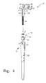
- the stem 22 includes a pair of telescoping stem components.
- the stem 22 includes an outer shell 28 with a stem shaft 30 telescoping outwardly therefrom.
- the outer shell 28 has an elongated bore 32 defined therein.
- a distal end of the stem shaft 30 is positioned in the elongated bore 32, whereas the proximal end of the stem shaft 30 extends out of the bore 32.
- the bore 32 is stepped in configuration having a number of bore sections with differing diameters, each of which shares a common centre line.
- the stem shaft 30 includes a platform 34 having a shaft 36 extending downwardly from a bottom surface thereof.
- the shaft 36 is stepped in configuration having a number of shaft sections with differing diameters, each of which shares a common centre line.
- the platform 34 has a pair of flanges 38 secured to an upper surface thereof.
- Each of the flanges 38 has a hole 40 defined therein.
- an actuator for adjusting the offset of the femoral prosthesis 20 is positioned between the flanges 38.
- the stem shaft 30 is moved relative to the outer shell 28 by an actuator 42.
- the actuator 42 may be embodied as any type of actuator for post-operatively telescoping or otherwise moving the stem shaft 30 relative to the outer shell 28.
- the actuator 42 is operable to bi-directionally move the stem shaft 30 relative to the outer shell 28.
- the actuator 42 is operable to extend the stem shaft 30 out of the outer shell 28 thereby increasing the length of the prosthesis 20, and is also operable to retract the stem shaft 30 into the outer shell 28 thereby decreasing the length of the prosthesis 20.
- the actuator 42 is embodied as a magnetic drive actuator 44 that is operated by an external (e.g., trans-cutaneous) electromagnetic source.
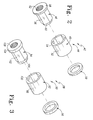
- the magnetic drive actuator 44 includes a magnet 46, a sleeve 48, and a cap 50.
- the magnet 46 may be constructed with any type of implantable magnetic material, whereas the sleeve 48 and the cap 50 may be made from implantable non-magnetic materials such as cobalt chrome or titanium.
- the magnet 46 is embodied as a cylindrically-shaped body 52 having a bore 54 extending through it.
- the bore 54 has an internal hex-shaped configuration which corresponds with an external hex-shaped body 56 of the sleeve 48.
- An annular flange 58 is secured to one end of the hex-shaped body 56 of the sleeve 48.
- a annular rim 60 is secured to the other end of the hex-shaped body 56 of the sleeve 48.
- the cap 50 is press fit or otherwise secured onto the rim 60.
- the magnet 46 is retained on the sleeve 48 on one end by the flange 58 and on the other end by the cap 50.
- the interface of the hex-shaped surfaces facilitates transfer of rotational force from the magnet 46 to the sleeve 48.
- the sleeve 48 has an internally threaded bore 62 extending through it. As will be described below in greater detail, a threaded portion 64 of the stem shaft 30 is meshed with the threaded bore 62 of the magnetic drive actuator 44.
- the magnetic drive actuator 44 is positioned in a bore section 66 of the elongated bore 32 of the outer shell 28.
- the distal end of the magnetic drive actuator 44 is maintained in the bore section 66 by a shoulder 68 defined in the outer shell 28.
- the proximal end of the magnetic drive actuator 44 is maintained in the bore section by a pair of retaining clips 70. As such, the magnetic drive actuator 44 is free to rotate within the bore 32, but is prevented from moving axially within the bore 32.
- the threaded portion 64 of the stem shaft 30 is threaded through the threaded bore 62 of the magnetic drive actuator 44.
- rotation of the magnet 46 causes axial movement of the stem shaft 30.
- rotation of the sleeve 48 causes the threads of the sleeve 48 to engage the threads of the shaft 30 which in turn axially moves the shaft 30 into or out of the bore 32 (depending on the direction of rotation of the sleeve 48).
- rotation of the magnet 46 (and hence the sleeve 48) in the general direction of arrow 122 of FIG. 6 causes extension of the stem shaft 30 as indicated by arrow 124.
- rotation of the magnet 46 (and hence the sleeve 48) in the general direction of arrow 126 of FIG. 6 causes retraction of the stem shaft 30 as indicated by arrow 128.
- the stroke of the stem shaft 30 is limited distally by the depth of the elongated bore 32.
- a screw 72 is threaded through a hole 74 in the sidewall of the outer shell 28. The tip of the screw 72 translates within a slot 76 defined in the side of a shaft portion 78 of the stem shaft 30. Such a configuration prevents rotation of the stem shaft 30 relative to the outer shell 28. Moreover, the screw 72 engages the distal side wall of the slot 76 to limit the stroke of the stem shaft 30.
- the head 24 includes a pair of head components.
- the head 24 includes medial head component 80 and a lateral head component 82.
- the neck 26 of the head 24 is defined in the medial head component 80.
- the medial head component 80 and the lateral head component 82 are secured to one another by the use of a dovetail joint. As such, the head components move in unison in the medial/lateral direction along the platform 34 of the stem shaft 30.
- the medial head component 80 has a cavity 84 defined therein.
- the cavity 84 of the medial head component 80 houses an actuator 88 which is operable to bi-directionally move the head components 80, 82 relative to the platform 34 of the stem shaft 30.
- the actuator 88 may be embodied as any type of actuator for post-operatively moving the medial head component 80 and the lateral head component 82 relative to the stem 22.
- the actuator 88 is operable to extend the head 24 thereby increasing the offset of the prosthesis 20, and is also operable to retract the head 24 thereby decreasing the offset of the prosthesis 20.
- the actuator 88 is embodied as a magnetic drive actuator 90 that is operated by an external (e.g., trans-cutaneous) electromagnetic source.
- the magnetic drive actuator 90 includes a magnet 92, a sleeve 94, and a cap 96.
- the magnet 92 may be constructed with any type of implantable magnetic material, whereas the sleeve 94 and the cap 96 may be made from implantable non-magnetic materials such as cobalt chrome or titanium.
- the magnet 92 is embodied as a cylindrically-shaped body 98 having a bore 100 extending through it.
- the bore 100 has an internal hex-shaped configuration which corresponds with an external hex-shaped body 102 of the sleeve 94.
- An annular nange 104 is secured to one end of the hex-shaped body 102 of the sleeve 94.
- An annular rim 106 is secured to the other end of the hex-shaped body 102 of the sleeve 94.
- the cap 96 is press fit or otherwise secured onto the rim 106.
- the magnet 92 is retained on the sleeve 94 on one end by the flange 104 and on the other end by the cap 96.
- the interface of the hex-shaped surfaces facilitates transfer of rotational force from the magnet 92 to the sleeve 94.
- the sleeve 94 has an internally threaded bore 108 extending through it. As will be described below in greater detail, a threaded portion 110 of a head shaft 112 is meshed with the threaded bore 108 of the magnetic drive actuator 90.
- the magnetic drive actuator 90 is positioned in the actuator cavity 84 of the head components 80.
- the magnetic drive actuator 90 is positioned between the flanges 38 extending out of the platform 34 of the stem shaft 30. As such, the magnetic drive actuator 90 is free to rotate, but is prevented from moving axially by the flanges 38.
- the head shaft 112 extends between the head medial head component 80 and the lateral head component 82.
- the medial end of the head shaft 112 is positioned in a blind bore 114 defined in the medial head component 80.
- the lateral end of the head shaft 112 has a generally rectangularly shaped flange 116 extending therefrom.
- the flange 116 is positioned in a corresponding cavity 86 defined in the lateral head component 82 thereby preventing rotation of the head shaft 112.
- the threaded portion 110 of the head shaft 112 is threaded through the threaded bore 108 of the magnetic drive actuator 90.
- rotation of the magnet 92 causes axial movement of the head components 80, 82 relative to the stem shaft 30.
- rotation of the sleeve 94 causes the threads of the sleeve 94 to engage the threads of the head shaft 112 which in turn causes axial movement of the head shaft 112 thereby moving the head components 80, 82 along the platform 34 of the stem shaft 30.
- rotation of the magnet 92 (and hence the sleeve 94) in the general direction of arrow 130 of FIG. 7 causes movement of the head components 80, 82 in the medial direction (as indicated by arrow 132) thereby increasing the offset of the prosthesis 20.
- the patient's femur Prior to implantation of the stem 22, the patient's femur is surgically prepared. Specifically, the patient's femur is, for example, reamed and/or broached to form the bore in the medullary canal. Thereafter, the bore is filled, or partially filled, with bone cement. The bone cement may then be allowed to "set-up" for a period of time. Thereafter, the stem 22 is implanted into the femur. Specifically, the distal tip of the stem 22 is first advanced into the opening in the proximal end portion of the prepared femur and thereafter advanced down the medullary canal. The head 24 of the prosthesis 20 extends out of the medullary canal of the femur.
- the femoral prosthesis 20 may be utilized to secure the patient's femur for movement relative to the patient's pelvis.
- the spherically-shaped prosthetic femoral head (not shown) secured to the neck 26 of the head 24 is positioned to bear on either the patient's natural acetabulum or a prosthetic socket in the form of a prosthetic acetabular cup (not shown) which has been implanted into the patient's pelvis to replace his or her acetabulum.
- the femoral prosthesis 20 and the natural or artificial acetabulum collectively function as a system which replaces the natural "ball and socket" joint of the patient's hip.
- the prosthesis 20 may be adjusted along a number of different axes. For example, the prosthesis 20 may be adjust along a first axis to change the length of the prosthesis, and adjusted along a second axis to change the offset of the prosthesis.
- an external signal generating device 118 may be used.
- the signal generating device 118 is operated to generate a magnetic field, such as a parallel magnetic field, which drives (i.e., rotates) the magnetic drive actuator 44 in the general direction of arrow 122 of FIG. 6.
- a magnetic field such as a parallel magnetic field
- the signal generating device 118 may be operated to increase the length of the prosthesis by a desired amount. It should also be appreciated that the signal generating device 118 effectuates rotation of the magnetic drive actuator 44 trans-cutaneously thereby eliminating the need to surgically gain access to the prosthesis 20 to increase the length thereof.
- the external signal generating device 118 may be operated to generate a magnetic field, such as a parallel magnetic field, which drives (i.e., rotates) the magnetic drive actuator 44 in the general direction of arrow 126 of FIG. 6.
- a magnetic field such as a parallel magnetic field
- the magnetic drive actuator 44 drives (i.e., rotates) the magnetic drive actuator 44 in the general direction of arrow 126 of FIG. 6.
- rotation of the magnet 46 (and hence the sleeve 48) of the magnetic drive actuator 44 causes axial movement of the stem shaft 30.
- rotation of the sleeve 48 in the general direction of arrow 126 causes the threads of the sleeve 48 to engage the threads of the shaft 30 which in turn retracts the shaft 30 into the bore 32 (as indicated by arrow 128 in FIG. 6).
- the signal generating device 118 may be operated to decrease the length of the prosthesis by a desired amount. It should also be appreciated that the signal generating device 118 effectuates rotation of the magnetic drive actuator 44 trans-cutaneously thereby eliminating the need to surgically gain access to the prosthesis 20 to decrease the length thereof.
- an external signal generating device 120 (or the signal generating device 118 if it so configured) may be used.
- the signal generating device 120 is operated to generate a magnetic field, such as an end-to-end magnetic field, which drives (i.e., rotates) the magnetic drive actuator 90 in the general direction of arrow 130 of FIG. 7.
- a magnetic field such as an end-to-end magnetic field
- rotation of the magnet 92 (and hence the sleeve 94) of the magnetic drive actuator 90 causes axial movement of the head components 80, 82 relative to the stem 22.
- rotation of the sleeve 94 in the general direction of arrow 130 causes the threads of the sleeve 94 to engage the threads of the head shaft 112 which in turn causes axial movement of the head shaft 112 thereby moving the head components 80, 82 in the medial direction (as indicated by arrow 132) relative to the platform 34 of the stem shaft 30 which increases the offset of the prosthesis 20.
- the signal generating device 120 may be operated to increase the offset of the prosthesis 20 by a desired amount. It should also be appreciated that the signal generating device 120 effectuates rotation of the magnetic drive actuator 90 trans-cutaneously thereby eliminating the need to surgically gain access to the prosthesis 20 to change the offset thereof.
- the external signal generating device 120 may be operated to generate a magnetic field, such as an end-to-end magnetic field, which drives (i.e., rotates) the magnetic drive actuator 90 in the general direction of arrow 134 of FIG. 7.
- a magnetic field such as an end-to-end magnetic field
- rotation of the magnet 92 (and hence the sleeve 94) of the magnetic drive actuator 90 causes axial movement of the head components 80, 82 relative to the stem 22.
- rotation of the sleeve 94 in the general direction of arrow 134 causes the threads of the sleeve 94 to engage the threads of the head shaft 112 which in turn causes axial movement of the head shaft 112 thereby moving the head components 80, 82 in the lateral direction (as indicated by arrow 136) relative to the platform 34 of the stem shaft 30 which decreases the offset of the prosthesis 20.
- the signal generating device 120 may be operated to decrease the offset of the prosthesis 20 by a desired amount. It should also be appreciated that the signal generating device 120 effectuates rotation of the magnetic drive actuator 90 trans-cutaneously thereby eliminating the need to surgically gain access to the prosthesis 20 to change the offset thereof.
- the invention might be used in other procedures.
- the invention might be used the construction of a hip prosthesis for implanted using minimally invasive techniques. These and other hip prostheses may be used in either primary or revision procedures.
- the invention might also be used in the construction of an adjustable tibial tray for use in a knee procedure.
- the invention might also be used in the construction of a spinal implant used to treat, amongst other things, scoliosis.
- the invention might also be used in the construction of fracture management devices thereby providing the device with the ability to compress a fracture site through external fixators, nails, and/or plates.
- the invention might also be used in the construction of expandable and contractible nails for use in, amongst other things, trauma procedures.
- the prosthesis 20 may also be configured to adjust along additional axes of movement.
- the prosthesis 20 may be embodied with an adjustable neck 26 which may be extended and retracted by use of an actuator similar to the actuators 42, 88.
Landscapes
- Health & Medical Sciences (AREA)
- Orthopedic Medicine & Surgery (AREA)
- Cardiology (AREA)
- Oral & Maxillofacial Surgery (AREA)
- Transplantation (AREA)
- Engineering & Computer Science (AREA)
- Biomedical Technology (AREA)
- Heart & Thoracic Surgery (AREA)
- Vascular Medicine (AREA)
- Life Sciences & Earth Sciences (AREA)
- Animal Behavior & Ethology (AREA)
- General Health & Medical Sciences (AREA)
- Public Health (AREA)
- Veterinary Medicine (AREA)
- Prostheses (AREA)
Abstract
Description
- The present invention relates generally to orthopaedic prostheses.
- During the lifetime of a patient, it may be necessary to perform a joint replacement procedure on the patient as a result of, for example, disease or trauma. The joint replacement procedure may involve the use of a prosthesis which is implanted into one or more of the patient's bones. In the case of a hip replacement procedure, a femoral prosthesis is implanted into the patient's femur. The femoral prosthesis typically includes an elongated stem component which is implanted into the medullary canal of the patient's femur and a spherically-shaped head which bears against the patient's acetabulum or a prosthetic replacement acetabular cup. In the case of a shoulder replacement procedure, a humeral prosthesis is implanted into the patient's humerus. The humeral prosthesis includes an elongated stem component which is implanted into the medullary canal of the patient's humerus and a spherically-shaped head which bears against the patient's glenoid or a prosthetic replacement glenoid component. In the case of a knee replacement procedure, a tibial prosthesis is implanted into the patient's tibia. The condyle surfaces of the patient's femur, or the condyle surfaces of a replacement femoral component, bear against the tibial prosthesis.
- Subsequent to implantation, there is occasionally the need to adjust the prosthesis. For example, it may be necessary to adjust the prosthesis to correct a surgical error or correct for subsidence of the implant. Such adjustments necessitate one or more revision surgeries.
- Moreover, each year in the United States approximately 650 to 700 children under the age twenty are diagnosed with a malignant bone tumour. When presented with these types of cases, the surgeon can either amputate the entire limb or try to preserve it. To preserve the limb, the cancerous portion of the bone is removed. This surgery typically involves the removal of one or both of the growth plates. Because the residual bone cannot grow at the same speed as the contra lateral bone, a modular endoprosthesis is often implanted. As the child grows, more surgeries are required to lengthen the device. Depending on the age and condition of the patient, the number of surgeries that the patient has to endure can be greater than twenty. Specifically, for the young patient to grow properly with an modular endoprosthesis, multiple surgeries must be completed to continually lengthen the device or replace it with a new, longer one. After the patient has reached his/her full height, it may be necessary to replace the endoprosthesis again with a permanent endoprosthesis.
- In one aspect, the invention provides an adjustable prosthesis includes a first component which may be moved relative to a second component by use of an trans-cutaneous signal.
- The prosthesis may include a telescoping stem having an adjustable length.
- The prosthesis may include a long bone prosthesis having an adjustable length and an adjustable offset.
- The prosthesis may be bi-directionally adjustable along one or more axes of movement.
- The prosthesis may include a tibial component.
- The trans-cutaneous signal may include a magnetic field.
- The prosthesis may be used in a method which includes the steps of implanting the prosthesis and thereafter post-operatively adjusting the prosthesis.
- The prosthesis of the invention can be used in a method of operating an adjustable prosthesis, the method comprising the steps of:
- implanting a stem of the adjustable prosthesis into a medullary canal of a long bone,
- implanting a head of the adjustable prosthesis into a bone socket,
- generating a first trans-cutaneous signal to cause extension of the stem, and
- generating a second trans-cutaneous signal to cause extension of the head.
- The prosthesis of the invention can be used in a method of operating an adjustable prosthesis, the method comprising the steps of:
- implanting a stem of the adjustable prosthesis into a medullary canal of a long bone,
- generating a first trans-cutaneous signal to cause extension of the stem, and
- generating a second trans-cutaneous signal to cause retraction of the stem.
- Embodiments of the invention will now be described by way of example with reference to the accompanying drawings, in which:
- FIG. 1 is a cross sectional view of an adjustable femoral prosthesis;
- FIG. 2 is an exploded perspective view of a magnetic drive actuator that is operable to adjust the length of the femoral prosthesis of FIG. 1;
- FIG. 3 is an exploded perspective view of a magnetic drive actuator that is operable to adjust the offset of the femoral prosthesis of FIG. 1;
- FIG. 4 is an exploded perspective view of the stem of the femoral prosthesis of FIG. 1;
- FIG. 5 is an exploded perspective view of the head of the femoral prosthesis of FIG. 1;
- FIG. 6 is a perspective view showing the length of the femoral prosthesis of FIG. 1 being adjusted by an external signal generator; and
- FIG. 7 is a view similar to FIG. 6, but showing the offset of the femoral prosthesis being adjusted by tile external signal generator.
- Referring to the drawings, FIGS. 1 to 7 show an adjustable
femoral prosthesis 20 for implantation into a patient's femur during performance of a hip replacement procedure. It should be appreciated that although the invention is described with reference to its use in the performance of a hip replacement procedure, it might be used for implantation into other bones of the body. For example, the invention might be used in the construction of a prosthesis for implantation into the humerus, radius, ulna, tibia, fibula, or any of the metatarsals or metacarpals. - The
femoral prosthesis 20 includes astem 22 and ahead 24. Theprosthesis 20 is configured to be implanted into the femur of a patient in order to replace certain natural features of the patient's femur as a result of, for example, disease or trauma. Theprosthesis 20 is implanted into a surgically prepared (e.g., reamed and/or broached) medullary canal of the femur. - The
stem 22 and thehead 24 of theprosthesis 20 may be utilized to secure the patient's femur for movement relative to the patient's pelvis. In particular, a portion of thehead 24 is positioned to bear on either the patient's natural acetabulum or a prosthetic socket in the form of a prosthetic cup (not shown) which has been implanted into the patient's pelvis to replace his or her acetabulum. In such a manner, theprosthesis 20 and the natural or artificial acetabulum collectively function as a system which replaces the natural "ball and socket" joint of the patient's hip. - Both the
stem 22 and thehead 24 may be made of materials conventionally utilized in the construction of prosthetic implants. For example, thestem 22 and thehead 24 may be constructed from implantable metals such as stainless steel, cobalt chrome, or titanium. Thestem 22 and thehead 24 may also be constructed with non-metallic materials such as implant-grade polymers or ceramics. - The
stem 22 may be embodied in a number of different configurations in order to fit the needs of a given patient's anatomy and provide a variety of geometries and sizes. In particular, thestem 22 may be configured in various different lengths to conform to the patient's anatomy (e.g., a relativelylong stem 22 for use with a long femur, a relativelyshort stem 22 for use with a short femur, etcetera). Moreover, thestem 22 may also be embodied in a bow-shaped configuration if required by a given patient's anatomy. Yet further, thestem 22 may also be embodied in various diameters as required by a given patient's anatomy. - The
head 24 includes aneck 26 extending outwardly from the body thereof. A generally spherically shaped prosthesis (not shown) that mimics a natural femoral head is taper fit or otherwise secured to theneck 26. - The
stem 22 is implanted into an elongated bore surgically formed in the patient's femur. As such, thestem 22 may be constructed with materials which promote bone ingrowth into the outer surfaces of thestem 22. Moreover, since bone cement may be used to secure thestem 22 in the femur, the materials from which thestem 22 is constructed may also be selected to promote interdigitation of bone cement into the outer surfaces of thestem 22. - As shown in FIGS. 1 and 4, the
stem 22 includes a pair of telescoping stem components. In the exemplary embodiment described herein, thestem 22 includes anouter shell 28 with astem shaft 30 telescoping outwardly therefrom. Theouter shell 28 has an elongated bore 32 defined therein. As shown in FIG. 1, a distal end of thestem shaft 30 is positioned in the elongated bore 32, whereas the proximal end of thestem shaft 30 extends out of thebore 32. Thebore 32 is stepped in configuration having a number of bore sections with differing diameters, each of which shares a common centre line. - The
stem shaft 30 includes aplatform 34 having ashaft 36 extending downwardly from a bottom surface thereof. Theshaft 36 is stepped in configuration having a number of shaft sections with differing diameters, each of which shares a common centre line. Theplatform 34 has a pair offlanges 38 secured to an upper surface thereof. Each of theflanges 38 has ahole 40 defined therein. As will be described in greater detail below, an actuator for adjusting the offset of thefemoral prosthesis 20 is positioned between theflanges 38. - The
stem shaft 30 is moved relative to theouter shell 28 by anactuator 42. Theactuator 42 may be embodied as any type of actuator for post-operatively telescoping or otherwise moving thestem shaft 30 relative to theouter shell 28. As will herein be described in more detail, theactuator 42 is operable to bi-directionally move thestem shaft 30 relative to theouter shell 28. In particular, theactuator 42 is operable to extend thestem shaft 30 out of theouter shell 28 thereby increasing the length of theprosthesis 20, and is also operable to retract thestem shaft 30 into theouter shell 28 thereby decreasing the length of theprosthesis 20. In the exemplary embodiment described herein, theactuator 42 is embodied as amagnetic drive actuator 44 that is operated by an external (e.g., trans-cutaneous) electromagnetic source. - As shown in FIG. 2, the
magnetic drive actuator 44 includes amagnet 46, asleeve 48, and acap 50. Themagnet 46 may be constructed with any type of implantable magnetic material, whereas thesleeve 48 and thecap 50 may be made from implantable non-magnetic materials such as cobalt chrome or titanium. In the exemplary embodiment described herein, themagnet 46 is embodied as a cylindrically-shapedbody 52 having abore 54 extending through it. Thebore 54 has an internal hex-shaped configuration which corresponds with an external hex-shapedbody 56 of thesleeve 48. Anannular flange 58 is secured to one end of the hex-shapedbody 56 of thesleeve 48. Aannular rim 60 is secured to the other end of the hex-shapedbody 56 of thesleeve 48. As shown in FIG. 2, thecap 50 is press fit or otherwise secured onto therim 60. As such, themagnet 46 is retained on thesleeve 48 on one end by theflange 58 and on the other end by thecap 50. The interface of the hex-shaped surfaces facilitates transfer of rotational force from themagnet 46 to thesleeve 48. Thesleeve 48 has an internally threaded bore 62 extending through it. As will be described below in greater detail, a threadedportion 64 of thestem shaft 30 is meshed with the threaded bore 62 of themagnetic drive actuator 44. - As shown in FIGS. 1 and 4, the
magnetic drive actuator 44 is positioned in abore section 66 of the elongated bore 32 of theouter shell 28. The distal end of themagnetic drive actuator 44 is maintained in thebore section 66 by ashoulder 68 defined in theouter shell 28. The proximal end of themagnetic drive actuator 44 is maintained in the bore section by a pair of retaining clips 70. As such, themagnetic drive actuator 44 is free to rotate within thebore 32, but is prevented from moving axially within thebore 32. - As shown in FIG. 1, the threaded
portion 64 of thestem shaft 30 is threaded through the threaded bore 62 of themagnetic drive actuator 44. As such, rotation of the magnet 46 (and hence the sleeve 48) causes axial movement of thestem shaft 30. Specifically, rotation of thesleeve 48 causes the threads of thesleeve 48 to engage the threads of theshaft 30 which in turn axially moves theshaft 30 into or out of the bore 32 (depending on the direction of rotation of the sleeve 48). For example, rotation of the magnet 46 (and hence the sleeve 48) in the general direction ofarrow 122 of FIG. 6 causes extension of thestem shaft 30 as indicated byarrow 124. Conversely, rotation of the magnet 46 (and hence the sleeve 48) in the general direction ofarrow 126 of FIG. 6 causes retraction of thestem shaft 30 as indicated byarrow 128. - The stroke of the
stem shaft 30 is limited distally by the depth of theelongated bore 32. Ascrew 72 is threaded through ahole 74 in the sidewall of theouter shell 28. The tip of thescrew 72 translates within aslot 76 defined in the side of ashaft portion 78 of thestem shaft 30. Such a configuration prevents rotation of thestem shaft 30 relative to theouter shell 28. Moreover, thescrew 72 engages the distal side wall of theslot 76 to limit the stroke of thestem shaft 30. - As shown in FIGS. 1 and 5, the
head 24 includes a pair of head components. In the exemplary embodiment described herein, thehead 24 includesmedial head component 80 and alateral head component 82. Theneck 26 of thehead 24 is defined in themedial head component 80. As shown in FIGS. 1 and 5, themedial head component 80 and thelateral head component 82 are secured to one another by the use of a dovetail joint. As such, the head components move in unison in the medial/lateral direction along theplatform 34 of thestem shaft 30. - The
medial head component 80 has acavity 84 defined therein. Thecavity 84 of themedial head component 80 houses an actuator 88 which is operable to bi-directionally move thehead components platform 34 of thestem shaft 30. Theactuator 88 may be embodied as any type of actuator for post-operatively moving themedial head component 80 and thelateral head component 82 relative to thestem 22. In particular, theactuator 88 is operable to extend thehead 24 thereby increasing the offset of theprosthesis 20, and is also operable to retract thehead 24 thereby decreasing the offset of theprosthesis 20. In the exemplary embodiment described herein, theactuator 88 is embodied as amagnetic drive actuator 90 that is operated by an external (e.g., trans-cutaneous) electromagnetic source. - As shown in FIG. 3, the
magnetic drive actuator 90 includes amagnet 92, asleeve 94, and acap 96. Themagnet 92 may be constructed with any type of implantable magnetic material, whereas thesleeve 94 and thecap 96 may be made from implantable non-magnetic materials such as cobalt chrome or titanium. In the exemplary embodiment described herein, themagnet 92 is embodied as a cylindrically-shapedbody 98 having abore 100 extending through it. Thebore 100 has an internal hex-shaped configuration which corresponds with an external hex-shapedbody 102 of thesleeve 94. Anannular nange 104 is secured to one end of the hex-shapedbody 102 of thesleeve 94. Anannular rim 106 is secured to the other end of the hex-shapedbody 102 of thesleeve 94. As shown in FIG. 3, thecap 96 is press fit or otherwise secured onto therim 106. As such, themagnet 92 is retained on thesleeve 94 on one end by theflange 104 and on the other end by thecap 96. The interface of the hex-shaped surfaces facilitates transfer of rotational force from themagnet 92 to thesleeve 94. Thesleeve 94 has an internally threadedbore 108 extending through it. As will be described below in greater detail, a threadedportion 110 of ahead shaft 112 is meshed with the threaded bore 108 of themagnetic drive actuator 90. - As shown in FIG. 1, the
magnetic drive actuator 90 is positioned in theactuator cavity 84 of thehead components 80. Themagnetic drive actuator 90 is positioned between theflanges 38 extending out of theplatform 34 of thestem shaft 30. As such, themagnetic drive actuator 90 is free to rotate, but is prevented from moving axially by theflanges 38. - As shown in FIG. 1, the
head shaft 112 extends between the headmedial head component 80 and thelateral head component 82. The medial end of thehead shaft 112 is positioned in a blind bore 114 defined in themedial head component 80. The lateral end of thehead shaft 112 has a generally rectangularly shaped flange 116 extending therefrom. The flange 116 is positioned in a correspondingcavity 86 defined in thelateral head component 82 thereby preventing rotation of thehead shaft 112. The threadedportion 110 of thehead shaft 112 is threaded through the threaded bore 108 of themagnetic drive actuator 90. As such, rotation of the magnet 92 (and hence the sleeve 94) causes axial movement of thehead components stem shaft 30. Specifically, rotation of thesleeve 94 causes the threads of thesleeve 94 to engage the threads of thehead shaft 112 which in turn causes axial movement of thehead shaft 112 thereby moving thehead components platform 34 of thestem shaft 30. For example, rotation of the magnet 92 (and hence the sleeve 94) in the general direction ofarrow 130 of FIG. 7 causes movement of thehead components prosthesis 20. Conversely, rotation of the magnet 92 (and hence the sleeve 94) in the general direction ofarrow 134 of FIG. 7 causes movement of thehead components prosthesis 20. - Implantation of the
femoral prosthesis 20 will now be described in greatut detail. Prior to implantation of thestem 22, the patient's femur is surgically prepared. Specifically, the patient's femur is, for example, reamed and/or broached to form the bore in the medullary canal. Thereafter, the bore is filled, or partially filled, with bone cement. The bone cement may then be allowed to "set-up" for a period of time. Thereafter, thestem 22 is implanted into the femur. Specifically, the distal tip of thestem 22 is first advanced into the opening in the proximal end portion of the prepared femur and thereafter advanced down the medullary canal. Thehead 24 of theprosthesis 20 extends out of the medullary canal of the femur. - In such a way, the
femoral prosthesis 20 may be utilized to secure the patient's femur for movement relative to the patient's pelvis. In particular, when implanted in such a manner, the spherically-shaped prosthetic femoral head (not shown) secured to theneck 26 of thehead 24 is positioned to bear on either the patient's natural acetabulum or a prosthetic socket in the form of a prosthetic acetabular cup (not shown) which has been implanted into the patient's pelvis to replace his or her acetabulum. As a result, thefemoral prosthesis 20 and the natural or artificial acetabulum collectively function as a system which replaces the natural "ball and socket" joint of the patient's hip. - Subsequent to implantation of the
femoral prosthesis 20, it may become desirable to adjust theprosthesis 20. Theprosthesis 20 may be adjusted along a number of different axes. For example, theprosthesis 20 may be adjust along a first axis to change the length of the prosthesis, and adjusted along a second axis to change the offset of the prosthesis. - To increase the length of the
prosthesis 20, such as may be needed from time to time when theprosthesis 20 is implanted in a growing child, an externalsignal generating device 118 may be used. Thesignal generating device 118 is operated to generate a magnetic field, such as a parallel magnetic field, which drives (i.e., rotates) themagnetic drive actuator 44 in the general direction ofarrow 122 of FIG. 6. As described above, such rotation of the magnet 46 (and hence the sleeve 48) of themagnetic drive actuator 44 causes axial movement of thestem shaft 30. Specifically, rotation of thesleeve 48 in the general direction ofarrow 122 causes the threads of thesleeve 48 to engage the threads of theshaft 30 which in turn extends theshaft 30 out of the bore 32 (as indicated byarrow 124 in FIG. 6). Such extension of thestem shaft 30 increases the length of theprosthesis 20. It should be appreciated that thesignal generating device 118 may be operated to increase the length of the prosthesis by a desired amount. It should also be appreciated that thesignal generating device 118 effectuates rotation of themagnetic drive actuator 44 trans-cutaneously thereby eliminating the need to surgically gain access to theprosthesis 20 to increase the length thereof. - Conversely, to decrease the length of the
prosthesis 20, such as may be needed for contraction of the femur, the externalsignal generating device 118 may be operated to generate a magnetic field, such as a parallel magnetic field, which drives (i.e., rotates) themagnetic drive actuator 44 in the general direction ofarrow 126 of FIG. 6. As described above, such rotation of the magnet 46 (and hence the sleeve 48) of themagnetic drive actuator 44 causes axial movement of thestem shaft 30. Specifically, rotation of thesleeve 48 in the general direction ofarrow 126 causes the threads of thesleeve 48 to engage the threads of theshaft 30 which in turn retracts theshaft 30 into the bore 32 (as indicated byarrow 128 in FIG. 6). Such retraction of thestem shaft 30 decreases the length of theprosthesis 20. It should be appreciated that thesignal generating device 118 may be operated to decrease the length of the prosthesis by a desired amount. It should also be appreciated that thesignal generating device 118 effectuates rotation of themagnetic drive actuator 44 trans-cutaneously thereby eliminating the need to surgically gain access to theprosthesis 20 to decrease the length thereof. - To increase the offset of the
prosthesis 20, such as may be needed from time to time subsequent to when theprosthesis 20 is implanted, an external signal generating device 120 (or thesignal generating device 118 if it so configured) may be used. Thesignal generating device 120 is operated to generate a magnetic field, such as an end-to-end magnetic field, which drives (i.e., rotates) themagnetic drive actuator 90 in the general direction ofarrow 130 of FIG. 7. As described above, rotation of the magnet 92 (and hence the sleeve 94) of themagnetic drive actuator 90 causes axial movement of thehead components stem 22. Specifically, rotation of thesleeve 94 in the general direction ofarrow 130 causes the threads of thesleeve 94 to engage the threads of thehead shaft 112 which in turn causes axial movement of thehead shaft 112 thereby moving thehead components platform 34 of thestem shaft 30 which increases the offset of theprosthesis 20. It should be appreciated that thesignal generating device 120 may be operated to increase the offset of theprosthesis 20 by a desired amount. It should also be appreciated that thesignal generating device 120 effectuates rotation of themagnetic drive actuator 90 trans-cutaneously thereby eliminating the need to surgically gain access to theprosthesis 20 to change the offset thereof. - To decrease the offset of the
prosthesis 20, such as may be needed from time to time subsequent to when theprosthesis 20 is implanted, the externalsignal generating device 120 may be operated to generate a magnetic field, such as an end-to-end magnetic field, which drives (i.e., rotates) themagnetic drive actuator 90 in the general direction ofarrow 134 of FIG. 7. As described above, rotation of the magnet 92 (and hence the sleeve 94) of themagnetic drive actuator 90 causes axial movement of thehead components stem 22. Specifically, rotation of thesleeve 94 in the general direction ofarrow 134 causes the threads of thesleeve 94 to engage the threads of thehead shaft 112 which in turn causes axial movement of thehead shaft 112 thereby moving thehead components platform 34 of thestem shaft 30 which decreases the offset of theprosthesis 20. It should be appreciated that thesignal generating device 120 may be operated to decrease the offset of theprosthesis 20 by a desired amount. It should also be appreciated that thesignal generating device 120 effectuates rotation of themagnetic drive actuator 90 trans-cutaneously thereby eliminating the need to surgically gain access to theprosthesis 20 to change the offset thereof. - As described above, although the invention has been described with reference to its use in the performance of a hip replacement procedure, the invention might be used in other procedures. For example, the invention might be used the construction of a hip prosthesis for implanted using minimally invasive techniques. These and other hip prostheses may be used in either primary or revision procedures. The invention might also be used in the construction of an adjustable tibial tray for use in a knee procedure. The invention might also be used in the construction of a spinal implant used to treat, amongst other things, scoliosis. The invention might also be used in the construction of fracture management devices thereby providing the device with the ability to compress a fracture site through external fixators, nails, and/or plates. The invention might also be used in the construction of expandable and contractible nails for use in, amongst other things, trauma procedures.
- The
prosthesis 20 may also be configured to adjust along additional axes of movement. For example, theprosthesis 20 may be embodied with anadjustable neck 26 which may be extended and retracted by use of an actuator similar to theactuators
Claims (17)
- An implantable orthopaedic prosthesis, comprising:an outer shell having an elongated bore defined therein,a stem shaft having a first end positioned in the elongated bore and a second end extending out of the elongated bore,a first actuator operable to move the stem shaft relative to the outer shell along a first axis,a neck adapted to receive a prosthetic head, anda second actuator operable to move the neck relative to the outer shell along a second axis, the second axis being different than the first axis.
- The prosthesis of claim 1, wherein the first actuator comprises a magnet positioned in the elongated bore, and rotation of the magnet causes movement of the stem shaft relative to the outer shell.
- The prosthesis of claim 2, wherein rotation of the magnet in a first rotational direction causes movement of the stem shaft relative to the outer shell in a first axial direction, and rotation of the magnet in a second rotational direction causes movement of the stem shaft relative to the outer shell in a second axial direction, the second axial direction being different than the first axial direction.
- The prosthesis of claim 2, wherein the first actuator further comprises a sleeve secured to the magnet, the sleeve has a threaded bore extending through it, the stem shaft has a threaded shaft portion intermeshed with the threaded bore of the sleeve, and rotation of the sleeve causes movement of the stem shaft relative to the outer shell.
- The prosthesis of claim 4, wherein rotation of the sleeve in a first rotational direction causes movement of the stem shaft relative to the outer shell in a first axial direction, and rotation of the sleeve in a second rotational direction causes movement of the stem shaft relative to the outer shell in a second axial direction, the second axial direction being different than the first axial direction.
- The prosthesis of claim 1, further comprising a first head component and a second head component, wherein the neck is defined in the first head component, and the first head component and the second head component are movable relative to the outer shell along the second axis.
- The prosthesis of claim 1, further comprising a head shaft extending between the first head component and the second head component.
- The prosthesis of claim 7, wherein the second actuator comprises a magnet, and rotation of the magnet causes axial movement of the head shaft thereby moving the first head component and the second head component relative to the outer sheii.
- The prosthesis of claim 8, wherein rotation of the magnet in a first rotational direction causes movement of the first head component and the second head component relative to the outer shell in a first axial direction, and rotation of the magnet in a second rotational direction causes movement of the first head component and the second head component relative to the outer shell in a second axial direction, the second axial direction being different than the first axial direction.
- The prosthesis of claim 8, wherein the second actuator further comprises a sleeve secured to the magnet, the sleeve has a threaded bore extending through it, the head shaft has a threaded shaft portion intermeshed with the threaded bore of the sleeve, and rotation of the sleeve causes axial movement of the head shaft thereby moving the first head component and the second head component relative to the outer shell.
- The prosthesis of claim 10, wherein rotation of the sleeve in a first rotational direction causes movement of the first head component and the second head component relative to the outer shell in a first axial direction, and rotation of the sleeve in a second rotational direction causes movement of the first head component and the second head component relative to the outer shell in a second axial direction, the second axial direction being different than the first axial direction.
- The prosthesis of claim 1, wherein the first actuator is operable to move the stem shaft relative to the outer shell along the first axis in both a first axial direction and a second, opposite axial direction.
- The prosthesis of claim 1, wherein the second actuator is operable to move the neck relative to the outer shell along the second axis in both a first axial direction and a second, opposite axial direction.
- The prosthesis of claim 1, wherein the first actuator is operable to move the stem shaft relative to the outer shell along the first axis in both a first axial direction and a second, opposite axial direction, and the second actuator is operable to move the neck relative to the outer shell along the second axis in both a first axial direction and a second, opposite axial direction.
- An implantable orthopaedic prosthesis, comprising:a stem having a first stem component and a second stem component, the first stem component and the second stem component being movable relative to one another along a first axis,a first actuator operable to move the first stem component and the second stem component relative to one another,a first head component movable relative to the first stem component along a second axis which is different than the first axis, anda second actuator operable to move the first head component relative to the first stem component.
- An implantable orthopaedic prosthesis, comprising:a first actuator configured to move a first portion of the prosthesis along a first axis, anda second actuator configured to move a second portion of the prosthesis along a second axis, the second axis being different than the first axis.
- An implantable orthopaedic prosthesis, comprising:an outer shell having an elongated bore defined therein,a stem shaft having a first end positioned in the elongated bore and a second end extending out of the elongated bore, anda first magnet positioned in the elongated bore, the first magnet being rotatable relative to the stem shaft, wherein rotation of the first magnet causes movement of the stem shaft relative to the outer shell.
Applications Claiming Priority (1)
| Application Number | Priority Date | Filing Date | Title |
|---|---|---|---|
| US10/880,859 US7481841B2 (en) | 2004-06-30 | 2004-06-30 | Adjustable orthopaedic prosthesis and associated method |
Publications (3)
| Publication Number | Publication Date |
|---|---|
| EP1611868A2 true EP1611868A2 (en) | 2006-01-04 |
| EP1611868A3 EP1611868A3 (en) | 2006-04-05 |
| EP1611868B1 EP1611868B1 (en) | 2012-01-25 |
Family
ID=35079157
Family Applications (1)
| Application Number | Title | Priority Date | Filing Date |
|---|---|---|---|
| EP05253570A Expired - Lifetime EP1611868B1 (en) | 2004-06-30 | 2005-06-09 | Adjustable orthopaedic prosthesis |
Country Status (4)
| Country | Link |
|---|---|
| US (1) | US7481841B2 (en) |
| EP (1) | EP1611868B1 (en) |
| AT (1) | ATE542495T1 (en) |
| AU (1) | AU2005202522B2 (en) |
Cited By (16)
| Publication number | Priority date | Publication date | Assignee | Title |
|---|---|---|---|---|
| WO2010085659A1 (en) | 2009-01-22 | 2010-07-29 | St. Jude Medical | Magnetic docking system and method for the long term adjustment of an implantable device |
| DE102009011661A1 (en) * | 2009-03-04 | 2010-09-09 | Wittenstein Ag | growing prosthesis |
| EP2303395A4 (en) * | 2008-07-29 | 2012-08-22 | St Jude Medical Cardiology Div | Method and system for long term adjustment of an implantable device |
| US8673001B2 (en) | 2002-08-29 | 2014-03-18 | StJude Medical, Cardiology Division, Inc. | Methods for controlling the internal circumference of an anatomic orifice or lumen |
| US8758372B2 (en) | 2002-08-29 | 2014-06-24 | St. Jude Medical, Cardiology Division, Inc. | Implantable devices for controlling the size and shape of an anatomical structure or lumen |
| US8778021B2 (en) | 2009-01-22 | 2014-07-15 | St. Jude Medical, Cardiology Division, Inc. | Post-operative adjustment tool, minimally invasive attachment apparatus, and adjustable tricuspid ring |
| US8864823B2 (en) | 2005-03-25 | 2014-10-21 | StJude Medical, Cardiology Division, Inc. | Methods and apparatus for controlling the internal circumference of an anatomic orifice or lumen |
| EP2712306A4 (en) * | 2011-05-17 | 2014-11-26 | Smith & Nephew Inc | TELESCOPIC CENTROMEDULAR NAIL AND ITS ACTUATION MECHANISM |
| US9107750B2 (en) | 2007-01-03 | 2015-08-18 | St. Jude Medical, Cardiology Division, Inc. | Implantable devices for controlling the size and shape of an anatomical structure or lumen |
| US9333096B2 (en) | 2014-04-21 | 2016-05-10 | The University Of Massachusetts | Prosthetic limb |
| RU2593224C1 (en) * | 2015-05-22 | 2016-08-10 | Денис Игоревич Варфоломеев | Hip joint endoprosthesis |
| WO2016155686A1 (en) * | 2015-03-27 | 2016-10-06 | Knöchel Klaus G | Artificial hip joint implant |
| US9492276B2 (en) | 2005-03-25 | 2016-11-15 | St. Jude Medical, Cardiology Division, Inc. | Methods and apparatus for controlling the internal circumference of an anatomic orifice or lumen |
| GB2566320A (en) * | 2017-09-11 | 2019-03-13 | Sikander Murtuza | Adjustable bone implants |
| WO2021170612A3 (en) * | 2020-02-25 | 2021-10-21 | Waldemar Link Gmbh & Co. Kg | Extracorporeally length-adjustable implant system, and length-adjustable implant component |
| US12629225B2 (en) | 2020-02-25 | 2026-05-19 | Waldemar Link Gmbh & Co. Kg | Extracorporeally length-adjustable implant system, and length-adjustable implant component |
Families Citing this family (92)
| Publication number | Priority date | Publication date | Assignee | Title |
|---|---|---|---|---|
| US7955357B2 (en) | 2004-07-02 | 2011-06-07 | Ellipse Technologies, Inc. | Expandable rod system to treat scoliosis and method of using the same |
| US9717537B2 (en) * | 2004-08-30 | 2017-08-01 | Globus Medical, Inc. | Device and method for treatment of spinal deformity |
| US7763053B2 (en) * | 2004-08-30 | 2010-07-27 | Gordon Jeffrey D | Implant for correction of spinal deformity |
| US8439915B2 (en) * | 2004-09-29 | 2013-05-14 | The Regents Of The University Of California | Apparatus and methods for magnetic alteration of anatomical features |
| US7559951B2 (en) * | 2004-09-30 | 2009-07-14 | Depuy Products, Inc. | Adjustable, remote-controllable orthopaedic prosthesis and associated method |
| FR2901991B1 (en) * | 2006-06-13 | 2021-07-09 | Arnaud Andre Soubeiran | INTRACORPAL EXTENSION DEVICE MOUNTED IN TENSILE SCREW |
| US20080097606A1 (en) * | 2006-10-19 | 2008-04-24 | Cragg Andrew H | Knee joint prosthesis and hyaluronate compositions for treatment of osteoarthritis |
| US7862502B2 (en) | 2006-10-20 | 2011-01-04 | Ellipse Technologies, Inc. | Method and apparatus for adjusting a gastrointestinal restriction device |
| US12171904B2 (en) | 2006-10-30 | 2024-12-24 | Trs Holdings Llc | Mineral coated scaffolds |
| US8043299B2 (en) * | 2006-11-06 | 2011-10-25 | Janet Conway | Internal bone transport |
| JP2010522046A (en) * | 2007-03-22 | 2010-07-01 | ノヴァリン・オルソペディクス・インコーポレーテッド | Segmented intramedullary structure |
| US20080269767A1 (en) * | 2007-04-03 | 2008-10-30 | O'brien Michael F | Intra-operative t-square |
| US7753915B1 (en) * | 2007-06-14 | 2010-07-13 | August Eksler | Bi-directional bone length adjustment system |
| US20090112263A1 (en) * | 2007-10-30 | 2009-04-30 | Scott Pool | Skeletal manipulation system |
| US11202707B2 (en) | 2008-03-25 | 2021-12-21 | Nuvasive Specialized Orthopedics, Inc. | Adjustable implant system |
| US20100094302A1 (en) * | 2008-10-13 | 2010-04-15 | Scott Pool | Spinal distraction system |
| US11241257B2 (en) | 2008-10-13 | 2022-02-08 | Nuvasive Specialized Orthopedics, Inc. | Spinal distraction system |
| US8382756B2 (en) | 2008-11-10 | 2013-02-26 | Ellipse Technologies, Inc. | External adjustment device for distraction device |
| US8197490B2 (en) * | 2009-02-23 | 2012-06-12 | Ellipse Technologies, Inc. | Non-invasive adjustable distraction system |
| US9622792B2 (en) * | 2009-04-29 | 2017-04-18 | Nuvasive Specialized Orthopedics, Inc. | Interspinous process device and method |
| EP2473116B1 (en) * | 2009-09-04 | 2019-12-04 | NuVasive Specialized Orthopedics, Inc. | Bone growth device |
| FR2949662B1 (en) | 2009-09-09 | 2011-09-30 | Arnaud Soubeiran | INTRA-BODY DEVICE FOR MOVING TISSUE |
| WO2011044586A1 (en) * | 2009-10-10 | 2011-04-14 | Simplicity Orthopedics, Inc. | Method and apparatus for restoring a joint, including the provision and use of a longitudinally-adjustable and rotationally-adjustable joint prosthesis |
| US20110178604A1 (en) * | 2010-01-18 | 2011-07-21 | Biomet Manufacturing Corp. | Expandable Endoprosthesis |
| US8333807B2 (en) * | 2010-03-05 | 2012-12-18 | Biomet Manufacturing Corp. | Method and apparatus for trialing and implanting a modular femoral hip |
| US8419743B2 (en) | 2010-03-05 | 2013-04-16 | Biomet Manufacturing Corp. | Assembly tool for modular implants and associated method |
| US8679130B2 (en) | 2010-03-05 | 2014-03-25 | Biomet Manufacturing, Llc | Guide assembly for lateral implants and associated methods |
| US8529569B2 (en) | 2010-03-05 | 2013-09-10 | Biomet Manufacturing, Llc | Method and apparatus for preparing a proximal femur |
| US8221432B2 (en) | 2010-03-05 | 2012-07-17 | Biomet Manufacturing Corp. | Method and apparatus for implanting a modular femoral hip |
| US8460393B2 (en) | 2010-03-05 | 2013-06-11 | Biomet Manufacturing Corp. | Modular lateral hip augments |
| FR2957776B1 (en) * | 2010-03-23 | 2013-02-15 | Arnaud Andre Soubeiran | DEVICE FOR MOVING TISSUES INSIDE THE ORGANISM, ESPECIALLY BONE TISSUES, WITH FIXED TRACTION SCREWS AND ROTATING NUT |
| US8641723B2 (en) | 2010-06-03 | 2014-02-04 | Orthonex LLC | Skeletal adjustment device |
| US9248043B2 (en) | 2010-06-30 | 2016-02-02 | Ellipse Technologies, Inc. | External adjustment device for distraction device |
| WO2012021378A2 (en) | 2010-08-09 | 2012-02-16 | Ellipse Technologies, Inc. | Maintenance feature in magnetic implant |
| US8282671B2 (en) | 2010-10-25 | 2012-10-09 | Orthonex | Smart device for non-invasive skeletal adjustment |
| US8721566B2 (en) | 2010-11-12 | 2014-05-13 | Robert A. Connor | Spinal motion measurement device |
| EP2468216B1 (en) * | 2010-12-23 | 2014-05-14 | Baumgart, Rainer, Dipl.-Ing. Dr. med. | Implantable prosthesis for replacing human hip or knee joints and the adjoining bone sections |
| WO2012112396A2 (en) | 2011-02-14 | 2012-08-23 | Ellipse Technologies, Inc. | Device and method for treating fractured bones |
| WO2012118843A1 (en) | 2011-02-28 | 2012-09-07 | Tissue Regeneration Systems, Inc. | Modular tissue scaffolds |
| BR112013029376A2 (en) | 2011-05-16 | 2017-01-31 | Smith & Nephew Inc | skeleton extension measurement |
| US10743794B2 (en) | 2011-10-04 | 2020-08-18 | Nuvasive Specialized Orthopedics, Inc. | Devices and methods for non-invasive implant length sensing |
| US10016220B2 (en) | 2011-11-01 | 2018-07-10 | Nuvasive Specialized Orthopedics, Inc. | Adjustable magnetic devices and methods of using same |
| AU2012362279A1 (en) | 2011-12-30 | 2014-07-24 | Howmedica Osteonics Corp. | Systems for preparing bone voids to receive a prosthesis |
| US9216086B2 (en) * | 2012-02-01 | 2015-12-22 | Zimmer, Inc. | Adjustable provisional component of a medical device |
| US8668692B1 (en) * | 2012-05-01 | 2014-03-11 | Eric M. Lindvall | Intramedullary linkage device, system, and method for implantation |
| US20130338714A1 (en) | 2012-06-15 | 2013-12-19 | Arvin Chang | Magnetic implants with improved anatomical compatibility |
| CN102895048B (en) * | 2012-09-14 | 2016-12-21 | SAMBU Medical株式会社 | The human body artificial skelecton of non-operative treatment extending length |
| NL2009592C2 (en) * | 2012-10-09 | 2014-04-14 | Cornelis Pieter Jan Visser | A medical device for the operative treatment of a proximal humerus fracture. |
| US9044281B2 (en) | 2012-10-18 | 2015-06-02 | Ellipse Technologies, Inc. | Intramedullary implants for replacing lost bone |
| CN104902854B (en) | 2012-10-29 | 2017-10-03 | 诺威适骨科专科公司 | Adjustable device for knee arthritis |
| US9179938B2 (en) | 2013-03-08 | 2015-11-10 | Ellipse Technologies, Inc. | Distraction devices and method of assembling the same |
| US9526513B2 (en) | 2013-03-13 | 2016-12-27 | Howmedica Osteonics Corp. | Void filling joint prosthesis and associated instruments |
| US10226242B2 (en) | 2013-07-31 | 2019-03-12 | Nuvasive Specialized Orthopedics, Inc. | Noninvasively adjustable suture anchors |
| US9801734B1 (en) | 2013-08-09 | 2017-10-31 | Nuvasive, Inc. | Lordotic expandable interbody implant |
| US10751094B2 (en) | 2013-10-10 | 2020-08-25 | Nuvasive Specialized Orthopedics, Inc. | Adjustable spinal implant |
| CN111345867A (en) | 2014-04-28 | 2020-06-30 | 诺威适骨科专科公司 | remote control |
| KR102588501B1 (en) | 2014-10-23 | 2023-10-11 | 누베이시브 스페셜라이즈드 오소페딕스, 인크. | Remotely adjustable interactive bone reshaping implant |
| EP4005515B1 (en) | 2014-12-26 | 2024-07-24 | NuVasive Specialized Orthopedics, Inc. | Systems for distraction |
| US10149763B2 (en) | 2015-01-12 | 2018-12-11 | Howmedica Osteonics Corp. | Multipurpose void filling prosthesis |
| CA2917676A1 (en) | 2015-01-13 | 2016-07-13 | Stryker European Holdings I, Llc | Growing rods and methods of use |
| US10238427B2 (en) | 2015-02-19 | 2019-03-26 | Nuvasive Specialized Orthopedics, Inc. | Systems and methods for vertebral adjustment |
| WO2017066774A1 (en) | 2015-10-16 | 2017-04-20 | Nuvasive Specialized Orthopedics, Inc. | Adjustable devices for treating arthritis of the knee |
| JP6953409B2 (en) | 2015-12-10 | 2021-10-27 | ニューベイシブ スペシャライズド オーソペディックス,インコーポレイテッド | External adjustment device for extension device |
| DK3407812T3 (en) | 2016-01-28 | 2020-09-21 | Nuvasive Specialized Orthopedics Inc | Bone transport system |
| WO2017139548A1 (en) | 2016-02-10 | 2017-08-17 | Nuvasive Specialized Orthopedics, Inc. | Systems and methods for controlling multiple surgical variables |
| WO2017201437A1 (en) | 2016-05-19 | 2017-11-23 | Auctus Surgical, Llc | Spinal curvature modulation systems |
| US12262917B2 (en) | 2016-05-19 | 2025-04-01 | Auctus Surgical, Inc. | Spinal curvature modulation systems and methods |
| EP3332746B1 (en) * | 2016-12-06 | 2019-12-04 | WALDEMAR LINK GmbH & Co. KG | Revision prosthesis shaft for a revision joint endoprosthesis |
| WO2018226834A1 (en) * | 2017-06-07 | 2018-12-13 | Clarkson University | Adjustable length orthopedic device |
| CN111031934B (en) | 2017-06-30 | 2024-02-20 | 加利福尼亚大学董事会 | Magnetic devices, systems and methods |
| CN107280747B (en) * | 2017-07-25 | 2024-04-02 | 魏巍 | Intramedullary pin |
| US11464618B2 (en) * | 2017-08-07 | 2022-10-11 | Providence Health & Services—Oregon | Intestinal lengthening device |
| US11446064B2 (en) | 2018-04-26 | 2022-09-20 | Stryker European Operations Holdings Llc | Orthopedic growing devices |
| TR201819751A2 (en) * | 2018-12-18 | 2020-07-21 | Dokuz Eyluel Ueniversitesi Rektoerluegue | Hip prosthesis with stem-free expansion |
| EP3922039A1 (en) | 2019-02-07 | 2021-12-15 | NuVasive Specialized Orthopedics, Inc. | Ultrasonic communication in medical devices |
| US11589901B2 (en) | 2019-02-08 | 2023-02-28 | Nuvasive Specialized Orthopedics, Inc. | External adjustment device |
| WO2021045946A1 (en) | 2019-09-03 | 2021-03-11 | Nuvasive Specialized Orthopedics, Inc. | Acoustic reporting for dynamic implants |
| US12605192B2 (en) | 2020-07-15 | 2026-04-21 | Globus Medical, Inc. | Ultrasonic communication in adjustable implants |
| CN111803796B (en) * | 2020-07-28 | 2024-09-03 | 姬涛 | External adjusting driving device for noninvasive electromagnetic extension prosthesis of orthopedics department |
| US12213708B2 (en) | 2020-09-08 | 2025-02-04 | Nuvasive Specialized Orthopedics, Inc. | Remote control module for adjustable implants |
| US12453645B2 (en) * | 2021-02-02 | 2025-10-28 | Depuy Ireland Unlimited Company | Trial neck and method |
| US11806054B2 (en) | 2021-02-23 | 2023-11-07 | Nuvasive Specialized Orthopedics, Inc. | Adjustable implant, system and methods |
| US11737787B1 (en) | 2021-05-27 | 2023-08-29 | Nuvasive, Inc. | Bone elongating devices and methods of use |
| AU2022325024A1 (en) | 2021-08-03 | 2024-02-22 | Nuvasive Specialized Orthopedics, Inc. | Adjustable implant |
| US11540924B1 (en) | 2022-02-14 | 2023-01-03 | Ezat EL-SAID | Remotely adjustable orthopedic prostheses |
| US12263088B2 (en) * | 2022-04-29 | 2025-04-01 | Globus Medical, Inc. | Expandable hip stem |
| US12551240B2 (en) | 2022-06-13 | 2026-02-17 | Nuvasive Inc. | Distraction loss magnet on-off mechanism |
| US12458417B2 (en) | 2022-08-15 | 2025-11-04 | Nuvasive Specialized Orthopedics Inc. | Intermedullary lengthening implant with integrated load sensor |
| US12508058B2 (en) | 2022-10-07 | 2025-12-30 | Nuvasive Specialized Orthopedics, Inc. | Adjustable tether implant |
| US12558133B2 (en) | 2023-04-25 | 2026-02-24 | Nuvasive, Inc. | Flat plate mechanisms for bone lengthening |
| US12533164B2 (en) | 2023-05-03 | 2026-01-27 | Nuvasive Specialized Orthopedics, Inc. | Adjustable implant |
| CN120114230A (en) * | 2025-03-18 | 2025-06-10 | 北京市春立正达医疗器械股份有限公司 | A modular, extendable and stable femoral stem prosthesis |
Citations (1)
| Publication number | Priority date | Publication date | Assignee | Title |
|---|---|---|---|---|
| US20040030395A1 (en) | 2000-04-13 | 2004-02-12 | Gordon Blunn | Surgical distraction device |
Family Cites Families (93)
| Publication number | Priority date | Publication date | Assignee | Title |
|---|---|---|---|---|
| CH581988A5 (en) * | 1974-04-09 | 1976-11-30 | Messerschmitt Boelkow Blohm | |
| US4024588A (en) * | 1974-10-04 | 1977-05-24 | Allo Pro A.G. | Artificial joints with magnetic attraction or repulsion |
| ES207117Y (en) * | 1974-10-25 | 1976-07-01 | Pares Avila | INTERNAL FIXING DEVICE FOR BONE FRACTURES. |
| IL48826A (en) * | 1976-01-13 | 1978-08-31 | Aginsky Yacov | Intramedullary compression nail for the treatment of bone fractures |
| DE2713837C2 (en) * | 1977-03-25 | 1978-10-26 | Erhard Dr. 1000 Berlin Westerhoff | Drive device for a distraction device |
| US4190044A (en) * | 1978-08-16 | 1980-02-26 | Wood Eugene W | Telescoping intermedullary pin |
| US4262665A (en) * | 1979-06-27 | 1981-04-21 | Roalstad W L | Intramedullary compression device |
| US4275717A (en) * | 1979-07-27 | 1981-06-30 | Zimmer Usa, Inc. | Intramedullary fixation device for fractured tubular bones |
| GB2094629B (en) * | 1981-03-14 | 1984-08-01 | Tsnii | Artifical hip knee and femur |
| EP0077868A1 (en) * | 1981-10-26 | 1983-05-04 | Nunzio Godoli | Hip prosthesis as expanding femoral component |
| US4453539A (en) * | 1982-03-01 | 1984-06-12 | The University Of Toledo | Expandable intramedullary nail for the fixation of bone fractures |
| US4502160A (en) * | 1983-10-27 | 1985-03-05 | Dow Corning Wright | Adjustable length prosthetic joint implant |
| US4681590A (en) * | 1986-06-18 | 1987-07-21 | John Tansey | Femoral stem prosthesis |
| DE8706999U1 (en) * | 1987-05-15 | 1987-07-23 | Howmedica GmbH, 2314 Schönkirchen | Endoprosthesis for femoral or tibial joint bone parts and adjacent bone sections |
| FR2632514B1 (en) * | 1988-06-09 | 1990-10-12 | Medinov Sarl | PROGRESSIVE CENTRO-MEDULAR NAIL |
| EP0390883B1 (en) | 1988-09-09 | 1994-12-07 | DRAENERT, Klaus, Dr.med. | Hip-joint prosthesis and use thereof |
| DE3921972C2 (en) * | 1989-07-04 | 1994-06-09 | Rainer Dr Med Baumgart | Intramedullary nail |
| US5059193A (en) * | 1989-11-20 | 1991-10-22 | Spine-Tech, Inc. | Expandable spinal implant and surgical method |
| US4946459A (en) * | 1989-12-04 | 1990-08-07 | Georgia Tech Research Corporation | Intramedullary device |
| US5236460A (en) * | 1990-02-12 | 1993-08-17 | Midas Rex Pneumatic Tools, Inc. | Vertebral body prosthesis |
| US5057103A (en) * | 1990-05-01 | 1991-10-15 | Davis Emsley A | Compressive intramedullary nail |
| US5108398A (en) * | 1990-10-16 | 1992-04-28 | Orthopaedic Research Institute | Orthopaedic knee fusion apparatus |
| US5102413A (en) * | 1990-11-14 | 1992-04-07 | Poddar Satish B | Inflatable bone fixation device |
| US5071435A (en) * | 1990-12-20 | 1991-12-10 | Albert Fuchs | Extendible bone prosthesis |
| US5123926A (en) * | 1991-02-22 | 1992-06-23 | Madhavan Pisharodi | Artificial spinal prosthesis |
| DE9115810U1 (en) * | 1991-12-20 | 1992-02-20 | Howmedica GmbH, 2314 Schönkirchen | Endoprosthesis for the knee joint |
| US5885283A (en) * | 1992-08-04 | 1999-03-23 | Gittleman; Neal B. | Osteogenic mandibular distention apparatus and method |
| US5466261A (en) * | 1992-11-19 | 1995-11-14 | Wright Medical Technology, Inc. | Non-invasive expandable prosthesis for growing children |
| US5626579A (en) * | 1993-02-12 | 1997-05-06 | The Cleveland Clinic Foundation | Bone transport and lengthening system |
| US5429638A (en) * | 1993-02-12 | 1995-07-04 | The Cleveland Clinic Foundation | Bone transport and lengthening system |
| US5358524A (en) | 1993-02-16 | 1994-10-25 | Wright Medical Technology, Inc. | Adjustable length prosthetic implant |
| US5356411A (en) * | 1993-02-18 | 1994-10-18 | Spievack Alan R | Bone transporter |
| US5350379A (en) * | 1993-02-18 | 1994-09-27 | Genesis Orthopedics | Bone and tissue lengthening device |
| US5536269A (en) * | 1993-02-18 | 1996-07-16 | Genesis Orthopedics | Bone and tissue lengthening device |
| US5516335A (en) * | 1993-03-24 | 1996-05-14 | Hospital For Joint Diseases Orthopaedic Institute | Intramedullary nail for femoral lengthening |
| US5364396A (en) * | 1993-03-29 | 1994-11-15 | Robinson Randolph C | Distraction method and apparatus |
| US6187004B1 (en) * | 1993-07-14 | 2001-02-13 | Jeffrey A. Fearon | Subcutaneous bone expansion device |
| US5358424A (en) * | 1993-08-11 | 1994-10-25 | Molex Incorporated | Electrical connector for high density ribbon cable |
| US5505733A (en) * | 1993-10-22 | 1996-04-09 | Justin; Daniel F. | Intramedullary skeletal distractor and method |
| US5415660A (en) * | 1994-01-07 | 1995-05-16 | Regents Of The University Of Minnesota | Implantable limb lengthening nail driven by a shape memory alloy |
| EP0792419B1 (en) * | 1994-11-16 | 1999-01-13 | Arnaud André Soubeiran | Device for mutually moving two bodies |
| US5879386A (en) * | 1994-12-13 | 1999-03-09 | Jore; Matthew B. | Magnetic prosthetic system |
| US5665122A (en) * | 1995-01-31 | 1997-09-09 | Kambin; Parviz | Expandable intervertebral cage and surgical method |
| FR2730406B1 (en) * | 1995-02-13 | 1997-08-14 | Medinov Sa | IMPROVED LENGTHENING DEVICE FOR LONG BONES |
| US5575790A (en) * | 1995-03-28 | 1996-11-19 | Rensselaer Polytechnic Institute | Shape memory alloy internal linear actuator for use in orthopedic correction |
| ES2105964B1 (en) * | 1995-04-11 | 1998-06-01 | Plaza Fernandez Rafael De | LINEAR EXPANDER FOR PROGRESSIVE CORRECTION OF CRANIOFACIAL DEFORMATIONS. |
| DE59606028D1 (en) * | 1995-04-21 | 2000-11-23 | Gerd Werding | NAIL FOR FIXING THE POSITION AND SHAPE OF BROKEN TUBULAR BONES |
| US6077265A (en) * | 1995-04-21 | 2000-06-20 | Werding; Gerd | Nail for fixing the position and shape of broken long bones |
| EP0770359A1 (en) * | 1995-10-05 | 1997-05-02 | Medicon e.G. Chirurgiemechaniker-Genossenschaft | Distraction device for bone segments |
| US5846245A (en) * | 1995-10-20 | 1998-12-08 | New York University | Bone-adjusting device |
| US5626581A (en) * | 1995-11-27 | 1997-05-06 | Volunteers For Medical Engineering | Implantable bone lengthening apparatus |
| AU715921B2 (en) * | 1995-12-01 | 2000-02-10 | Gurkan Altuna | Telescopic bone plate for use in bone lengthening by distraction osteogenesis |
| US5704938A (en) * | 1996-03-27 | 1998-01-06 | Volunteers For Medical Engineering | Implantable bone lengthening apparatus using a drive gear mechanism |
| US5704939A (en) * | 1996-04-09 | 1998-01-06 | Justin; Daniel F. | Intramedullary skeletal distractor and method |
| US5700263A (en) * | 1996-06-17 | 1997-12-23 | Schendel; Stephen A. | Bone distraction apparatus |
| GR1003032B (en) * | 1996-07-10 | 1998-12-16 | Intramedullary, flexible fracture fixation device, using bi-axial pre-stressing. | |
| US5895387A (en) * | 1996-10-09 | 1999-04-20 | Romulo Guerrero | Method of craniofacial bone distraction |
| US5885290A (en) * | 1996-12-09 | 1999-03-23 | Guerrero; Cesar A. | Intra-oral bone distraction device |
| NL1004873C2 (en) * | 1996-12-23 | 1998-06-24 | Univ Twente | Device for moving two objects together. |
| DE19700225A1 (en) * | 1997-01-07 | 1998-07-09 | Augustin Prof Dr Betz | Distraction device for moving two parts of a bone apart |
| US5827286A (en) * | 1997-02-14 | 1998-10-27 | Incavo; Stephen J. | Incrementally adjustable tibial osteotomy fixation device and method |
| EP1011464B1 (en) * | 1997-03-07 | 2008-01-23 | Disc-O-Tech Medical Technologies, Ltd. | Systems for percutaneous bone and spinal stabilization, fixation and repair |
| WO2001054598A1 (en) | 1998-03-06 | 2001-08-02 | Disc-O-Tech Medical Technologies, Ltd. | Expanding bone implants |
| IL128261A0 (en) * | 1999-01-27 | 1999-11-30 | Disc O Tech Medical Tech Ltd | Expandable element |
| US6033412A (en) * | 1997-04-03 | 2000-03-07 | Losken; H. Wolfgang | Automated implantable bone distractor for incremental bone adjustment |
| US6113599A (en) * | 1997-06-04 | 2000-09-05 | Kalpa Engineering, Inc. | Apparatus for internal mandibular distraction |
| DE19741757A1 (en) * | 1997-09-22 | 1999-03-25 | Sachse Hans E | Implantable hydraulic bone expansion device |
| US6336929B1 (en) * | 1998-01-05 | 2002-01-08 | Orthodyne, Inc. | Intramedullary skeletal distractor and method |
| DE19829523A1 (en) * | 1998-07-02 | 2000-01-05 | Michael Butsch | Distraction device for moving apart a one- or two-part, possibly separate bone |
| US6261289B1 (en) * | 1998-10-26 | 2001-07-17 | Mark Levy | Expandable orthopedic device |
| US6554833B2 (en) * | 1998-10-26 | 2003-04-29 | Expanding Orthopedics, Inc. | Expandable orthopedic device |
| DE19856062A1 (en) * | 1998-12-04 | 2000-06-15 | Wittenstein Gmbh & Co Kg | Distraction device |
| EP1212014A1 (en) | 1999-01-26 | 2002-06-12 | Javier Miguel Cabrera Contreras | A device for and method of replacing or repairing a joint |
| DE19906423A1 (en) * | 1999-02-16 | 2000-08-17 | Wittenstein Gmbh & Co Kg | Active marrow spike for drawing out sections of bone consists of two elements moving against each other and electrically operated driving element to supply spike with electrical energy via detachable plug-in element. |
| DE19908851A1 (en) * | 1999-03-01 | 2000-09-07 | Rainer Baumgart | Intramedullary nail for bone distraction |
| US6520991B2 (en) * | 1999-05-11 | 2003-02-18 | Donald R. Huene | Expandable implant for inter-vertebral stabilization, and a method of stabilizing vertebrae |
| US6358283B1 (en) * | 1999-06-21 | 2002-03-19 | Hoegfors Christian | Implantable device for lengthening and correcting malpositions of skeletal bones |
| US6673079B1 (en) * | 1999-08-16 | 2004-01-06 | Washington University | Device for lengthening and reshaping bone by distraction osteogenesis |
| US6277124B1 (en) * | 1999-10-27 | 2001-08-21 | Synthes (Usa) | Method and apparatus for ratcheting adjustment of bone segments |
| WO2001034045A1 (en) * | 1999-11-11 | 2001-05-17 | Synthes Ag Chur | Radially expandable intramedullary nail |
| WO2001049193A1 (en) * | 2000-01-03 | 2001-07-12 | Orthoscope Ltd. | Intramedullary support strut |
| FR2805451B1 (en) * | 2000-02-29 | 2002-04-19 | Arnaud Andre Soubeiran | IMPROVED DEVICE FOR MOVING TWO BODIES IN RELATION TO ONE ANOTHER, PARTICULARLY FOR REALIZING IMPLANTABLE SYSTEMS IN THE HUMAN BODY |
| US6425923B1 (en) * | 2000-03-07 | 2002-07-30 | Zimmer, Inc. | Contourable polymer filled implant |
| US6447514B1 (en) * | 2000-03-07 | 2002-09-10 | Zimmer | Polymer filled hip fracture fixation device |
| US6447515B1 (en) * | 2000-06-21 | 2002-09-10 | Russell Meldrum | Bioresorbable implant for fracture fixation |
| US6613052B1 (en) * | 2000-12-21 | 2003-09-02 | J. Gregory Kinnett | Multi-functional orthopedic surgical instrument and method of using same |
| GB0102141D0 (en) * | 2001-01-27 | 2001-03-14 | Davies John B C | Improvements in or relating to expandable bone nails |
| GB0106588D0 (en) * | 2001-03-16 | 2001-05-09 | Finsbury Dev Ltd | Tissue distracter |
| JP4175899B2 (en) * | 2001-05-23 | 2008-11-05 | オーソゴン テクノロジーズ 2003 リミテッド | Magnetically driven intramedullary device |
| US20030204267A1 (en) * | 2002-04-30 | 2003-10-30 | Hazebrouck Stephen A. | Modular limb preservation system |
| US7125423B2 (en) * | 2003-03-31 | 2006-10-24 | Depuy Products, Inc. | Intercalary prosthesis, kit and method |
| US20040193266A1 (en) * | 2003-03-31 | 2004-09-30 | Meyer Rudolf Xaver | Expansible prosthesis and magnetic apparatus |
| US7141067B2 (en) * | 2003-03-31 | 2006-11-28 | Depuy Products, Inc. | Intercalary implant |
-
2004
- 2004-06-30 US US10/880,859 patent/US7481841B2/en not_active Expired - Lifetime
-
2005
- 2005-06-09 AT AT05253570T patent/ATE542495T1/en active
- 2005-06-09 AU AU2005202522A patent/AU2005202522B2/en not_active Ceased
- 2005-06-09 EP EP05253570A patent/EP1611868B1/en not_active Expired - Lifetime
Patent Citations (1)
| Publication number | Priority date | Publication date | Assignee | Title |
|---|---|---|---|---|
| US20040030395A1 (en) | 2000-04-13 | 2004-02-12 | Gordon Blunn | Surgical distraction device |
Cited By (29)
| Publication number | Priority date | Publication date | Assignee | Title |
|---|---|---|---|---|
| US8673001B2 (en) | 2002-08-29 | 2014-03-18 | StJude Medical, Cardiology Division, Inc. | Methods for controlling the internal circumference of an anatomic orifice or lumen |
| US8945210B2 (en) | 2002-08-29 | 2015-02-03 | StJude Medical, Cardiology Division, Inc. | Implantable devices for controlling the internal circumference of an anatomic orifice or lumen |
| US8882830B2 (en) | 2002-08-29 | 2014-11-11 | StJude Medical, Cardiology Division, Inc. | Implantable devices for controlling the internal circumference of an anatomic orifice or lumen |
| US8758372B2 (en) | 2002-08-29 | 2014-06-24 | St. Jude Medical, Cardiology Division, Inc. | Implantable devices for controlling the size and shape of an anatomical structure or lumen |
| US9492276B2 (en) | 2005-03-25 | 2016-11-15 | St. Jude Medical, Cardiology Division, Inc. | Methods and apparatus for controlling the internal circumference of an anatomic orifice or lumen |
| US8864823B2 (en) | 2005-03-25 | 2014-10-21 | StJude Medical, Cardiology Division, Inc. | Methods and apparatus for controlling the internal circumference of an anatomic orifice or lumen |
| US9107750B2 (en) | 2007-01-03 | 2015-08-18 | St. Jude Medical, Cardiology Division, Inc. | Implantable devices for controlling the size and shape of an anatomical structure or lumen |
| US9326857B2 (en) | 2007-01-03 | 2016-05-03 | St. Jude Medical, Cardiology Division, Inc. | Implantable devices for controlling the size and shape of an anatomical structure or lumen |
| EP2303395A4 (en) * | 2008-07-29 | 2012-08-22 | St Jude Medical Cardiology Div | Method and system for long term adjustment of an implantable device |
| US9084677B2 (en) | 2008-07-29 | 2015-07-21 | St. Jude Medical, Cardiology Division, Inc. | Method and system for long term adjustment of an implantable device |
| WO2010085659A1 (en) | 2009-01-22 | 2010-07-29 | St. Jude Medical | Magnetic docking system and method for the long term adjustment of an implantable device |
| EP2381896A4 (en) * | 2009-01-22 | 2013-01-09 | St Jude Medical Cardiology Div | Magnetic docking system and method for the long term adjustment of an implantable device |
| US8778021B2 (en) | 2009-01-22 | 2014-07-15 | St. Jude Medical, Cardiology Division, Inc. | Post-operative adjustment tool, minimally invasive attachment apparatus, and adjustable tricuspid ring |
| US8808371B2 (en) | 2009-01-22 | 2014-08-19 | St. Jude Medical, Cardiology Division, Inc. | Post-operative adjustment tool, minimally invasive attachment apparatus, and adjustable tricuspid ring |
| EP2292187A3 (en) * | 2009-03-04 | 2011-04-06 | Wittenstein AG | Growth prosthetic |
| RU2497484C2 (en) * | 2009-03-04 | 2013-11-10 | Виттенштайн АГ | Growing prosthesis |
| DE102009011661A1 (en) * | 2009-03-04 | 2010-09-09 | Wittenstein Ag | growing prosthesis |
| AU2016250505B2 (en) * | 2011-05-17 | 2018-01-25 | Smith & Nephew, Inc | Telescoping IM nail and actuating mechanism |
| AU2012255781B2 (en) * | 2011-05-17 | 2016-09-08 | Smith & Nephew, Inc. | Telescoping IM nail and actuating mechanism |
| RU2634626C2 (en) * | 2011-05-17 | 2017-11-02 | Смит Энд Нефью, Инк. | Telescopic pit for intramedular osteosynthesis and control device |
| EP2712306A4 (en) * | 2011-05-17 | 2014-11-26 | Smith & Nephew Inc | TELESCOPIC CENTROMEDULAR NAIL AND ITS ACTUATION MECHANISM |
| US9333096B2 (en) | 2014-04-21 | 2016-05-10 | The University Of Massachusetts | Prosthetic limb |
| WO2016155686A1 (en) * | 2015-03-27 | 2016-10-06 | Knöchel Klaus G | Artificial hip joint implant |
| RU2593224C1 (en) * | 2015-05-22 | 2016-08-10 | Денис Игоревич Варфоломеев | Hip joint endoprosthesis |
| GB2566320A (en) * | 2017-09-11 | 2019-03-13 | Sikander Murtuza | Adjustable bone implants |
| GB2566320B (en) * | 2017-09-11 | 2019-11-13 | Sikander Murtuza | Adjustable bone implants |
| WO2021170612A3 (en) * | 2020-02-25 | 2021-10-21 | Waldemar Link Gmbh & Co. Kg | Extracorporeally length-adjustable implant system, and length-adjustable implant component |
| EP4279033A3 (en) * | 2020-02-25 | 2024-01-03 | Waldemar Link GmbH & Co. KG | Extracorporeal drive unit for an extracorporeal length-adjustable implant system, and length-adjustable implant system |
| US12629225B2 (en) | 2020-02-25 | 2026-05-19 | Waldemar Link Gmbh & Co. Kg | Extracorporeally length-adjustable implant system, and length-adjustable implant component |
Also Published As
| Publication number | Publication date |
|---|---|
| EP1611868B1 (en) | 2012-01-25 |
| US20060004459A1 (en) | 2006-01-05 |
| AU2005202522B2 (en) | 2010-05-27 |
| EP1611868A3 (en) | 2006-04-05 |
| AU2005202522A1 (en) | 2006-01-19 |
| ATE542495T1 (en) | 2012-02-15 |
| US7481841B2 (en) | 2009-01-27 |
Similar Documents
| Publication | Publication Date | Title |
|---|---|---|
| EP1611868B1 (en) | Adjustable orthopaedic prosthesis | |
| US7892290B2 (en) | Fluted sleeve hip prosthesis for modular stem | |
| US7559951B2 (en) | Adjustable, remote-controllable orthopaedic prosthesis and associated method | |
| US10143559B2 (en) | Stem for use in joint arthroplasty | |
| AU2005249515B2 (en) | Fluted intramedullary stem | |
| US20040225294A1 (en) | Acetabular reamer | |
| JP2004261574A (en) | Prosthetic implant surgical kit and orthopaedic implant assembly | |
| AU2003241631B2 (en) | Adjustable orthopaedic instrument | |
| EP1393695B1 (en) | Cemented prosthetic kit | |
| CA2942523A1 (en) | Femoral hip stem | |
| RU214900U1 (en) | HIP ENDOPROSTHESIS | |
| AU2007200241B2 (en) | Fluted sleeve hip prosthesis for modular stem | |
| Niedźwiedzki et al. | Reconstruction of massive acetabular bone loss with pelvic discontinuity | |
| Gaffurini et al. | Neck Modularity and CE/CE systems | |
| Kowaleski | Revision of BFXTM total hip replacement. | |
| AU2012200741A1 (en) | Fluted intramedullary stem |
Legal Events
| Date | Code | Title | Description |
|---|---|---|---|
| PUAI | Public reference made under article 153(3) epc to a published international application that has entered the european phase |
Free format text: ORIGINAL CODE: 0009012 |
|
| AK | Designated contracting states |
Kind code of ref document: A2 Designated state(s): AT BE BG CH CY CZ DE DK EE ES FI FR GB GR HU IE IS IT LI LT LU MC NL PL PT RO SE SI SK TR |
|
| AX | Request for extension of the european patent |
Extension state: AL BA HR LV MK YU |
|
| PUAL | Search report despatched |
Free format text: ORIGINAL CODE: 0009013 |
|
| AK | Designated contracting states |
Kind code of ref document: A3 Designated state(s): AT BE BG CH CY CZ DE DK EE ES FI FR GB GR HU IE IS IT LI LT LU MC NL PL PT RO SE SI SK TR |
|
| AX | Request for extension of the european patent |
Extension state: AL BA HR LV MK YU |
|
| 17P | Request for examination filed |
Effective date: 20060905 |
|
| AKX | Designation fees paid |
Designated state(s): AT BE BG CH CY CZ DE DK EE ES FI FR GB GR HU IE IS IT LI LT LU MC NL PL PT RO SE SI SK TR |
|
| 17Q | First examination report despatched |
Effective date: 20090406 |
|
| GRAP | Despatch of communication of intention to grant a patent |
Free format text: ORIGINAL CODE: EPIDOSNIGR1 |
|
| GRAS | Grant fee paid |
Free format text: ORIGINAL CODE: EPIDOSNIGR3 |
|
| GRAA | (expected) grant |
Free format text: ORIGINAL CODE: 0009210 |
|
| AK | Designated contracting states |
Kind code of ref document: B1 Designated state(s): AT BE BG CH CY CZ DE DK EE ES FI FR GB GR HU IE IS IT LI LT LU MC NL PL PT RO SE SI SK TR |
|
| REG | Reference to a national code |
Ref country code: GB Ref legal event code: FG4D |
|
| REG | Reference to a national code |
Ref country code: CH Ref legal event code: EP |
|
| REG | Reference to a national code |
Ref country code: CH Ref legal event code: NV Representative=s name: E. BLUM & CO. AG PATENT- UND MARKENANWAELTE VSP Ref country code: AT Ref legal event code: REF Ref document number: 542495 Country of ref document: AT Kind code of ref document: T Effective date: 20120215 |
|
| REG | Reference to a national code |
Ref country code: IE Ref legal event code: FG4D |
|
| REG | Reference to a national code |
Ref country code: DE Ref legal event code: R096 Ref document number: 602005032364 Country of ref document: DE Effective date: 20120329 |
|
| REG | Reference to a national code |
Ref country code: NL Ref legal event code: VDEP Effective date: 20120125 |
|
| LTIE | Lt: invalidation of european patent or patent extension |
Effective date: 20120125 |
|
| PG25 | Lapsed in a contracting state [announced via postgrant information from national office to epo] |
Ref country code: BE Free format text: LAPSE BECAUSE OF FAILURE TO SUBMIT A TRANSLATION OF THE DESCRIPTION OR TO PAY THE FEE WITHIN THE PRESCRIBED TIME-LIMIT Effective date: 20120125 Ref country code: NL Free format text: LAPSE BECAUSE OF FAILURE TO SUBMIT A TRANSLATION OF THE DESCRIPTION OR TO PAY THE FEE WITHIN THE PRESCRIBED TIME-LIMIT Effective date: 20120125 Ref country code: IS Free format text: LAPSE BECAUSE OF FAILURE TO SUBMIT A TRANSLATION OF THE DESCRIPTION OR TO PAY THE FEE WITHIN THE PRESCRIBED TIME-LIMIT Effective date: 20120525 Ref country code: BG Free format text: LAPSE BECAUSE OF FAILURE TO SUBMIT A TRANSLATION OF THE DESCRIPTION OR TO PAY THE FEE WITHIN THE PRESCRIBED TIME-LIMIT Effective date: 20120425 Ref country code: LT Free format text: LAPSE BECAUSE OF FAILURE TO SUBMIT A TRANSLATION OF THE DESCRIPTION OR TO PAY THE FEE WITHIN THE PRESCRIBED TIME-LIMIT Effective date: 20120125 |
|
| PG25 | Lapsed in a contracting state [announced via postgrant information from national office to epo] |
Ref country code: PT Free format text: LAPSE BECAUSE OF FAILURE TO SUBMIT A TRANSLATION OF THE DESCRIPTION OR TO PAY THE FEE WITHIN THE PRESCRIBED TIME-LIMIT Effective date: 20120525 Ref country code: PL Free format text: LAPSE BECAUSE OF FAILURE TO SUBMIT A TRANSLATION OF THE DESCRIPTION OR TO PAY THE FEE WITHIN THE PRESCRIBED TIME-LIMIT Effective date: 20120125 Ref country code: GR Free format text: LAPSE BECAUSE OF FAILURE TO SUBMIT A TRANSLATION OF THE DESCRIPTION OR TO PAY THE FEE WITHIN THE PRESCRIBED TIME-LIMIT Effective date: 20120426 Ref country code: FI Free format text: LAPSE BECAUSE OF FAILURE TO SUBMIT A TRANSLATION OF THE DESCRIPTION OR TO PAY THE FEE WITHIN THE PRESCRIBED TIME-LIMIT Effective date: 20120125 |
|
| REG | Reference to a national code |
Ref country code: AT Ref legal event code: MK05 Ref document number: 542495 Country of ref document: AT Kind code of ref document: T Effective date: 20120125 |
|
| PG25 | Lapsed in a contracting state [announced via postgrant information from national office to epo] |
Ref country code: CY Free format text: LAPSE BECAUSE OF FAILURE TO SUBMIT A TRANSLATION OF THE DESCRIPTION OR TO PAY THE FEE WITHIN THE PRESCRIBED TIME-LIMIT Effective date: 20120125 |
|
| PG25 | Lapsed in a contracting state [announced via postgrant information from national office to epo] |
Ref country code: SI Free format text: LAPSE BECAUSE OF FAILURE TO SUBMIT A TRANSLATION OF THE DESCRIPTION OR TO PAY THE FEE WITHIN THE PRESCRIBED TIME-LIMIT Effective date: 20120125 Ref country code: RO Free format text: LAPSE BECAUSE OF FAILURE TO SUBMIT A TRANSLATION OF THE DESCRIPTION OR TO PAY THE FEE WITHIN THE PRESCRIBED TIME-LIMIT Effective date: 20120125 Ref country code: CZ Free format text: LAPSE BECAUSE OF FAILURE TO SUBMIT A TRANSLATION OF THE DESCRIPTION OR TO PAY THE FEE WITHIN THE PRESCRIBED TIME-LIMIT Effective date: 20120125 Ref country code: SE Free format text: LAPSE BECAUSE OF FAILURE TO SUBMIT A TRANSLATION OF THE DESCRIPTION OR TO PAY THE FEE WITHIN THE PRESCRIBED TIME-LIMIT Effective date: 20120125 Ref country code: EE Free format text: LAPSE BECAUSE OF FAILURE TO SUBMIT A TRANSLATION OF THE DESCRIPTION OR TO PAY THE FEE WITHIN THE PRESCRIBED TIME-LIMIT Effective date: 20120125 Ref country code: DK Free format text: LAPSE BECAUSE OF FAILURE TO SUBMIT A TRANSLATION OF THE DESCRIPTION OR TO PAY THE FEE WITHIN THE PRESCRIBED TIME-LIMIT Effective date: 20120125 |
|
| PG25 | Lapsed in a contracting state [announced via postgrant information from national office to epo] |
Ref country code: SK Free format text: LAPSE BECAUSE OF FAILURE TO SUBMIT A TRANSLATION OF THE DESCRIPTION OR TO PAY THE FEE WITHIN THE PRESCRIBED TIME-LIMIT Effective date: 20120125 |
|
| PLBE | No opposition filed within time limit |
Free format text: ORIGINAL CODE: 0009261 |
|
| STAA | Information on the status of an ep patent application or granted ep patent |
Free format text: STATUS: NO OPPOSITION FILED WITHIN TIME LIMIT |
|
| 26N | No opposition filed |
Effective date: 20121026 |
|
| PG25 | Lapsed in a contracting state [announced via postgrant information from national office to epo] |
Ref country code: AT Free format text: LAPSE BECAUSE OF FAILURE TO SUBMIT A TRANSLATION OF THE DESCRIPTION OR TO PAY THE FEE WITHIN THE PRESCRIBED TIME-LIMIT Effective date: 20120125 Ref country code: MC Free format text: LAPSE BECAUSE OF NON-PAYMENT OF DUE FEES Effective date: 20120630 |
|
| REG | Reference to a national code |
Ref country code: DE Ref legal event code: R097 Ref document number: 602005032364 Country of ref document: DE Effective date: 20121026 |
|
| PG25 | Lapsed in a contracting state [announced via postgrant information from national office to epo] |
Ref country code: ES Free format text: LAPSE BECAUSE OF FAILURE TO SUBMIT A TRANSLATION OF THE DESCRIPTION OR TO PAY THE FEE WITHIN THE PRESCRIBED TIME-LIMIT Effective date: 20120506 |
|
| PG25 | Lapsed in a contracting state [announced via postgrant information from national office to epo] |
Ref country code: TR Free format text: LAPSE BECAUSE OF FAILURE TO SUBMIT A TRANSLATION OF THE DESCRIPTION OR TO PAY THE FEE WITHIN THE PRESCRIBED TIME-LIMIT Effective date: 20120125 |
|
| PG25 | Lapsed in a contracting state [announced via postgrant information from national office to epo] |
Ref country code: LU Free format text: LAPSE BECAUSE OF NON-PAYMENT OF DUE FEES Effective date: 20120609 |
|
| PG25 | Lapsed in a contracting state [announced via postgrant information from national office to epo] |
Ref country code: HU Free format text: LAPSE BECAUSE OF FAILURE TO SUBMIT A TRANSLATION OF THE DESCRIPTION OR TO PAY THE FEE WITHIN THE PRESCRIBED TIME-LIMIT Effective date: 20050609 |
|
| PGFP | Annual fee paid to national office [announced via postgrant information from national office to epo] |
Ref country code: IE Payment date: 20140610 Year of fee payment: 10 Ref country code: GB Payment date: 20140604 Year of fee payment: 10 |
|
| PGFP | Annual fee paid to national office [announced via postgrant information from national office to epo] |
Ref country code: CH Payment date: 20140612 Year of fee payment: 10 Ref country code: IT Payment date: 20140612 Year of fee payment: 10 Ref country code: DE Payment date: 20140603 Year of fee payment: 10 |
|
| PGFP | Annual fee paid to national office [announced via postgrant information from national office to epo] |
Ref country code: FR Payment date: 20140609 Year of fee payment: 10 |
|
| REG | Reference to a national code |
Ref country code: DE Ref legal event code: R119 Ref document number: 602005032364 Country of ref document: DE |
|
| PG25 | Lapsed in a contracting state [announced via postgrant information from national office to epo] |
Ref country code: IT Free format text: LAPSE BECAUSE OF NON-PAYMENT OF DUE FEES Effective date: 20150609 |
|
| REG | Reference to a national code |
Ref country code: CH Ref legal event code: PL |
|
| GBPC | Gb: european patent ceased through non-payment of renewal fee |
Effective date: 20150609 |
|
| REG | Reference to a national code |
Ref country code: IE Ref legal event code: MM4A |
|
| REG | Reference to a national code |
Ref country code: FR Ref legal event code: ST Effective date: 20160229 |
|
| PG25 | Lapsed in a contracting state [announced via postgrant information from national office to epo] |
Ref country code: LI Free format text: LAPSE BECAUSE OF NON-PAYMENT OF DUE FEES Effective date: 20150630 Ref country code: DE Free format text: LAPSE BECAUSE OF NON-PAYMENT OF DUE FEES Effective date: 20160101 Ref country code: IE Free format text: LAPSE BECAUSE OF NON-PAYMENT OF DUE FEES Effective date: 20150609 Ref country code: GB Free format text: LAPSE BECAUSE OF NON-PAYMENT OF DUE FEES Effective date: 20150609 Ref country code: CH Free format text: LAPSE BECAUSE OF NON-PAYMENT OF DUE FEES Effective date: 20150630 |
|
| PG25 | Lapsed in a contracting state [announced via postgrant information from national office to epo] |
Ref country code: FR Free format text: LAPSE BECAUSE OF NON-PAYMENT OF DUE FEES Effective date: 20150630 |