EP1611830A2 - Hard floor cleaner - Google Patents
Hard floor cleaner Download PDFInfo
- Publication number
- EP1611830A2 EP1611830A2 EP05014213A EP05014213A EP1611830A2 EP 1611830 A2 EP1611830 A2 EP 1611830A2 EP 05014213 A EP05014213 A EP 05014213A EP 05014213 A EP05014213 A EP 05014213A EP 1611830 A2 EP1611830 A2 EP 1611830A2
- Authority
- EP
- European Patent Office
- Prior art keywords
- filter
- float
- container
- cleaning device
- suction
- Prior art date
- Legal status (The legal status is an assumption and is not a legal conclusion. Google has not performed a legal analysis and makes no representation as to the accuracy of the status listed.)
- Withdrawn
Links
Images


Classifications
-
- A—HUMAN NECESSITIES
- A47—FURNITURE; DOMESTIC ARTICLES OR APPLIANCES; COFFEE MILLS; SPICE MILLS; SUCTION CLEANERS IN GENERAL
- A47L—DOMESTIC WASHING OR CLEANING; SUCTION CLEANERS IN GENERAL
- A47L11/00—Machines for cleaning floors, carpets, furniture, walls, or wall coverings
- A47L11/40—Parts or details of machines not provided for in groups A47L11/02 - A47L11/38, or not restricted to one of these groups, e.g. handles, arrangements of switches, skirts, buffers, levers
- A47L11/4036—Parts or details of the surface treating tools
- A47L11/4041—Roll shaped surface treating tools
-
- A—HUMAN NECESSITIES
- A47—FURNITURE; DOMESTIC ARTICLES OR APPLIANCES; COFFEE MILLS; SPICE MILLS; SUCTION CLEANERS IN GENERAL
- A47L—DOMESTIC WASHING OR CLEANING; SUCTION CLEANERS IN GENERAL
- A47L11/00—Machines for cleaning floors, carpets, furniture, walls, or wall coverings
- A47L11/34—Machines for treating carpets in position by liquid, foam, or vapour, e.g. by steam
-
- A—HUMAN NECESSITIES
- A47—FURNITURE; DOMESTIC ARTICLES OR APPLIANCES; COFFEE MILLS; SPICE MILLS; SUCTION CLEANERS IN GENERAL
- A47L—DOMESTIC WASHING OR CLEANING; SUCTION CLEANERS IN GENERAL
- A47L5/00—Structural features of suction cleaners
- A47L5/12—Structural features of suction cleaners with power-driven air-pumps or air-compressors, e.g. driven by motor vehicle engine vacuum
- A47L5/22—Structural features of suction cleaners with power-driven air-pumps or air-compressors, e.g. driven by motor vehicle engine vacuum with rotary fans
- A47L5/28—Suction cleaners with handles and nozzles fixed on the casings, e.g. wheeled suction cleaners with steering handle
-
- A—HUMAN NECESSITIES
- A47—FURNITURE; DOMESTIC ARTICLES OR APPLIANCES; COFFEE MILLS; SPICE MILLS; SUCTION CLEANERS IN GENERAL
- A47L—DOMESTIC WASHING OR CLEANING; SUCTION CLEANERS IN GENERAL
- A47L7/00—Suction cleaners adapted for additional purposes; Tables with suction openings for cleaning purposes; Containers for cleaning articles by suction; Suction cleaners adapted to cleaning of brushes; Suction cleaners adapted to taking-up liquids
- A47L7/0004—Suction cleaners adapted to take up liquids, e.g. wet or dry vacuum cleaners
- A47L7/0009—Suction cleaners adapted to take up liquids, e.g. wet or dry vacuum cleaners with means mounted on the nozzle; nozzles specially adapted for the recovery of liquid
-
- A—HUMAN NECESSITIES
- A47—FURNITURE; DOMESTIC ARTICLES OR APPLIANCES; COFFEE MILLS; SPICE MILLS; SUCTION CLEANERS IN GENERAL
- A47L—DOMESTIC WASHING OR CLEANING; SUCTION CLEANERS IN GENERAL
- A47L7/00—Suction cleaners adapted for additional purposes; Tables with suction openings for cleaning purposes; Containers for cleaning articles by suction; Suction cleaners adapted to cleaning of brushes; Suction cleaners adapted to taking-up liquids
- A47L7/0004—Suction cleaners adapted to take up liquids, e.g. wet or dry vacuum cleaners
- A47L7/0023—Recovery tanks
- A47L7/0028—Security means, e.g. float valves or level switches for preventing overflow
-
- A—HUMAN NECESSITIES
- A47—FURNITURE; DOMESTIC ARTICLES OR APPLIANCES; COFFEE MILLS; SPICE MILLS; SUCTION CLEANERS IN GENERAL
- A47L—DOMESTIC WASHING OR CLEANING; SUCTION CLEANERS IN GENERAL
- A47L7/00—Suction cleaners adapted for additional purposes; Tables with suction openings for cleaning purposes; Containers for cleaning articles by suction; Suction cleaners adapted to cleaning of brushes; Suction cleaners adapted to taking-up liquids
- A47L7/0004—Suction cleaners adapted to take up liquids, e.g. wet or dry vacuum cleaners
- A47L7/0023—Recovery tanks
- A47L7/0038—Recovery tanks with means for emptying the tanks
-
- A—HUMAN NECESSITIES
- A47—FURNITURE; DOMESTIC ARTICLES OR APPLIANCES; COFFEE MILLS; SPICE MILLS; SUCTION CLEANERS IN GENERAL
- A47L—DOMESTIC WASHING OR CLEANING; SUCTION CLEANERS IN GENERAL
- A47L7/00—Suction cleaners adapted for additional purposes; Tables with suction openings for cleaning purposes; Containers for cleaning articles by suction; Suction cleaners adapted to cleaning of brushes; Suction cleaners adapted to taking-up liquids
- A47L7/0004—Suction cleaners adapted to take up liquids, e.g. wet or dry vacuum cleaners
- A47L7/0042—Gaskets; Sealing means
Landscapes
- Nozzles For Electric Vacuum Cleaners (AREA)
- Cleaning In General (AREA)
Abstract
Description
- The present invention relates to floor care devices. More particularly, the present invention relates to a collection assembly for a hard floor cleaning device. However, it is to be appreciated that the present exemplary embodiment is also amenable to other like applications.
- Floor cleaning devices have been developed for cleaning hard floors to replace a conventional mop and bucket. Such devices often have an on-board tank for cleaning liquid and a cleaning head which is adapted to apply the cleaning liquid to the floor and remove dirty cleaning fluid therefrom. Vacuum cleaners are used for removal of dry dirt but are generally unsuited to the pick-up of liquids. It has been found advantageous to develop a single device able to perform both wet and dry floor cleaning operations. U.S. 6,101,668 to Grey, for example, discloses a floor cleaning device with a combined cleaning liquid and recovery tank which is carried on a handle of the device. Squeegees are mounted to a cleaning head for assisting in wet floor cleaning. One disadvantage in such a system is that it requires different separator systems for dry and wet cleaning modes.
- The present invention provides a new and improved floor cleaning device and method of use, which overcome the above-referenced problems and others.
- In accordance with one aspect of the present invention, a cleaning device is provided. The cleaning device includes a housing. A container is removably received by the housing. The container defines an inlet tube and an outlet. A suction source is mounted on the housing and is fluidly connected with the outlet of the container. An annular float selectively closes the fluid flowpath. The float is located in the container and surrounds the inlet tube.
- In accordance with another aspect of the invention, a cleaning device is provided. The device includes a housing. A container is removably received by the housing. The container defines an inlet and an outlet. A suction source is fluidly connected with the outlet of the container. A suction nozzle fluidly communicates with the inlet of the container and with the suction source via a fluid flowpath when the container is received by the housing. A float and filter assembly includes a filter, a filter receptacle which receives the filter; and a float which selectively closes the fluid flowpath. One of the float and the filter receptacle includes an engagement member for engagement with the other of the float and the filter receptacle whereby the float is movable in a direction parallel to a longitudinal axis of the container between a first position and a second position.
- In accordance with another aspect of the invention, a collection assembly for a surface cleaning device is provided. The collection assembly includes a container which comprises a compartment for receiving recovered cleaning fluid. The container has an inlet tube, through which the recovered fluid and entrained air enter the compartment, and an outlet. A filter and float assembly is carried by the container for filtering dirt from entrained air entering the container until a level of liquid in the container reaches a preselected level. The float surrounds the inlet tube.
- In accordance with another aspect of the invention, a method for cleaning a floor is provided. The method includes providing an upright cleaning device including a floor nozzle and an upper housing accomodating a container with a compartment for receiving recovered cleaning liquid. The container includes an inlet tube. A float and filter assembly is carried by the container. A cleaning liquid is applied to the floor. The cleaning liquid is suctioned from the floor into the compartment through the inlet tube. A flowpath of entrained air between the compartment and the filter is closed when a level of the dirty cleaning fluid causes the float to close. The float is guided between first and second positions in relation to the inlet tube.
- In accordance with another aspect of the invention, a cleaning device is provided. The cleaning device includes a base. A container is carried by the base for receiving dirt from a surface to be cleaned. A source of suction is in fluid communication with the container. A suction nozzle is carried by the base. The suction nozzle includes an inlet for receiving dirt from the surface to be cleaned and an outlet. The suction nozzle is movable, relative to the base, between a first position, in which the inlet is located adjacent the surface to be cleaned and a second position, in which the inlet is spaced from the surface. The suction nozzle outlet is in fluid communication with the container and with the source of suction in both the first and second positions of the suction nozzle.
- In accordance with another aspect of the invention, a cleaning device is provided. The device includes a base. A container is carried by the base for receiving dirt from a surface to be cleaned. A source of suction is in fluid communication with the container. A plurality of interchangeable suction nozzles are configured for selective connection with the base. Each of the suction nozzles includes an inlet for receiving dirt from the surface to be cleaned and an outlet.
- The advantages of the present invention will be readily apparent to those skilled in the art, upon a reading of the following disclosure and a review of the accompanying drawings.
- The invention is described in conjunction with accompanying drawings. The drawings are for purposes of illustrating exemplary embodiments of the invention and are not to be construed as limiting the invention to such embodiments. It is understood that the invention may take form in various components and arrangements of components and in various steps and arrangements of steps beyond those provided in the drawings and associated description.
- FIGURE 1 is a side elevational view of a floor cleaning device according to the present invention;
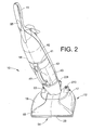
- FIGURE 2 is a top perspective view of the floor cleaning device of FIGURE 1;
- FIGURE 3 is an enlarged bottom perspective view of a lower end of the floor cleaning device of FIGURE 1;
- FIGURE 4 is an enlarged side sectional view of the floor cleaning device of FIGURE 1;
- FIGURE 5 is a top perspective view of a lower end of the cleaning device of FIGURE 1, with portions of the base housing and nozzle assembly removed for clarity;
- FIGURE 6 is an exploded perspective view of the base and lower portion of the handle assembly of the floor cleaner of FIGURE 1;
- FIGURE 7 is an enlarged side sectional view of the cleaning liquid and recovery container of FIGURE 4 and a first embodiment of a filter and float assembly;
- FIGURE 8 is an exploded perspective view of the cleaning fluid and recovery container and float and filter assembly of FIGURE 7;
- FIGURE 9 is a top view of the cleaning liquid and recovery container and filter and float assembly of FIGURE 7;
- FIGURE 10 is an enlarged side sectional view of the cleaning liquid and recovery container of FIGURE 7 with a float in an upper position;
- FIGURE 11 is an enlarged perspective view of a lower end of the cleaning device of FIGURE 1, with portions of the handle assembly and base removed;
- FIGURE 12 is an enlarged side sectional view of a second embodiment of a float and filter assembly in a cleaning liquid and recovery container according to the present invention;
- FIGURE 13 is an enlarged side sectional view of a lower end of the handle assembly of the cleaning device of FIGURE1;
- FIGURE 14 is an enlarged side sectional view of a rear portion of the base of the cleaning device of FIGURE 1;
- FIGURE 15 is a side sectional view of a base of a second embodiment of a floor cleaning device according to the present invention with a nozzle assembly in a lower position;
- FIGURE 16 is a side sectional view of the base of FIGURE 15 with the nozzle assembly in a raised position;
- FIGURE 17 is a perspective view of a base of a third embodiment of a floor cleaning device according to the present invention with a hard floor cleaning nozzle, and an upper housing portion removed for clarity;
- FIGURE 18 is a side view of the base of FIGURE 17 with the suction nozzle in a lowered position;
- FIGURE 19 is a side view of the base of FIGURE 17 with the suction nozzle in a raised position;
- FIGURE 20 is a perspective view of the base of FIGURE 17 with the hard floor nozzle removed; and
- FIGURE 21 is a side view of the base of FIGURE 17 with a carpet cleaning nozzle in a lower position.
- Referring now to the FIGURES, wherein the showings are for purposes of illustrating several preferred embodiments of the invention only and not for purposes of limiting the same, FIGURE 1 shows a
cleaning device 10 which includes abase 12 for contacting a hard floor surface and ahandle assembly 14, which is pivotally attached to the base. Ahand grip 15 is provided at an upper end of the handle assembly. During floor cleaning, thehandle assembly 14 is positioned at an acute angle to the direction of travel of thebase 12, and thehand grip 15 is held for directing the base across a floor surface to be cleaned. - With reference also to FIGURE 2, the
base 12 of the hard floor cleaning device includes abase housing 16 having anupper portion 17. Asuction nozzle 18 overlies theupper portion 17 and defines a suction inlet 20 (FIG. 3) for recovery of dry dirt and/or dirty liquid from the floor and anoutlet 21. An agitator 22 (FIG. 3), such as a rotating brush assembly, is carried by alower portion 23 of thebase housing 16 for scrubbing the floor. Thebase housing 16 also carries at least one flexible strip orsqueegee front squeegees squeegee support 27 to thesuction nozzle 18, such that they are positioned rearward and forward of thesuction inlet 20. Rotation members, such asrear wheels base housing 16, on either side of thehandle assembly 14. Forward rotation members, such as wheels orrollers carriage assembly 36 which is pivotally mounted at pivot points 37 to thelower portion 23 of the base housing 16 (FIG. 5). - The
suction nozzle 18 is formed from upper andlower members inlet 20 and theoutlet 21 and a portion of a fluid flowpath A therebetween. The nozzle assemblylower member 39 contacts theupper portion 17 of the base housing. - With reference now to FIGURE 4, the
handle assembly 14 includes anupper housing 40 in which is defined asocket 41. A removablefluid collection assembly 42 is received at least partially within thesocket 41 and serves as a recovery tank for dirty cleaning liquid and/or dry dirt and as a reservoir of fresh cleaning liquid. Thecollection assembly 42 may include acontainer 43 which defines first and second compartments for separately holding the cleaning liquid and dry dirt/dirty cleaning liquid which has been recovered from the floor. Specifically, thecontainer 43 has aninner section 44, which is mounted within anouter section 46 having anintegral handle 47. In cooperation, the twosections suction inlet 20, and areservoir chamber 50, between the inner andouter sections - While in the illustrated embodiment, the recovery chamber 48 and
reservoir chamber 50 are defined by asingle container 43, it is also contemplated that separate recovery and cleaning liquid tanks may be provided. Additionally, while thecontainer 43 is illustrated as being carried by thehandle assembly 14 of the cleaning device, it is also contemplated that the container may alternatively be carried in whole or in part by thebase 12 of the cleaning device. In yet another embodiment, the floor cleaning device is of the canister type and lacks a directing handle. In such an embodiment, thecontainer 43 can be carried by a wheeled housing and the suction nozzle fluidly connected to the wheeled housing by a wand. - A source of
suction 52, such as a fan and motor assembly, applies suction to the recovery chamber 48, thereby drawing dry dirt and/or dirty cleaning liquid and entrained air from thesuction inlet 20 on the base into the recovery chamber via asuction duct 53, which defines a portion of the flowpath marked by arrows A. In the illustrated embodiment, the fan andmotor assembly 52 is mounted within thehandle assembly housing 40, above thesocket 41, although other locations are also contemplated. - The hard
floor cleaning device 10 can be used for dry and wet modes of cleaning, as described in greater detail below. In the dry mode, aforward end 54 of the base 12 can be raised, relative to the floor surface, to improve pick up of dry dirt. Raising the base forward end 54 raises thesuction inlet 20 and squeegee(s) 24, 26 a small distance away from the floor surface. In the wet mode, theforward end 54 of the base can be lowered to allow thesqueegees - With reference now to FIGURE 5, which shows the base 12 with the
upper housing portion 17 of thebase housing 16 andsuction nozzle 18 removed, aheight adjustment mechanism 60 raises and lowers theforward end 54 of the base. The height adjustment mechanism includes a foot operatedpedal 62, pivotally mounted to the base housing. When depressed, the pedal 62 causes the front end of the wheeled carriage 36 (FIG. 3) to pivot, relative to the rest of the base, from a extended (lowered) position to a retracted (raised) position. With the carriage in its extended position, therollers lower portion 23 of thebase housing 16, thereby raising theforward end 54 of the base. With the carriage in its retracted position, the carriage is retracted into a downwardly opening pocket 63 (FIGURE 3) in thebase housing 16, thereby lowering theforward end 54 of the base. Further depression of thefoot pedal 62 returns thecarriage 36 to its extended position. Specifically, as shown in FIGURE 5, depression of the pedal pivots alever 64, overcoming the biasing force of aspring 65. In turn, the pivoting of thelever 64 actuates a pen-type actuator 66 with acam foot 68, best shown in exploded perspective view in FIGURE 6. Thepen type actuator 66 shifts thecam foot 68 in one direction. The cam foot rises up acamming surface 70 on thecarriage 36, raising the base housing and effectively lowering thefront rollers cam foot 68 in the opposite direction, returning theforward end 54 of the base 12 to the lowered position by retracting thecarriage 36. - In one embodiment, the
agitator 22 is fixed, relative to thebase housing 16, and is thus raised and lowered as theforward end 54 of the base is lowered. The agitator may be spaced from the floor surface in the raised (upper) position, or may maintain at least a limited contact with the floor. In another embodiment, theagitator 22 is free floating, so that it maintains contact with the floor in both raised and lowered positions. - With continued reference to FIGURE 6, the
brush assembly 22 includes aframe 80 formed from upper andlower frame members switch 85 mounted on the handle assembly 16 (FIG. 2) selectively supplies power to abrushroll motor 86. The brushroll motor is mounted to theframe 80 and drivably connected with abrushroll 88 by adrive belt 90. Thebrushroll 88 includesbristles 89 and is rotatably mounted to a forward end of theframe 80. Abrushroll cover 91 is mounted to theframe 80 to deflect clean fluid downwardly. The frame includesarms lower portion 23 of the base housing at pivot points 96, 98 so that thebrushroll 88 floats, relative to the base housing. The weight of the brushroll, optionally assisted by a bias spring (not shown) maintains thebrushroll 88 in contact with the floor surface in both the raised and lowered positions of thecarriage 36. - In the fixed brushroll embodiment, the
frame 80 is fixed against movement relative to thebase housing 16 so that thebrushroll 88 is raised and lowered as thefront end 54 of the base housing is raised and lowered. For example, forward ends of thearms bristles 89 of thebrushroll 88 are of sufficient length that they engage the floor even when thefront end 54 of the base is in the raised position. - With reference now to FIGURE 7, the
collection assembly 42 for clean and recovered cleaning liquid includes a vertically extendingsuction tube 98, which defines part of afluid inlet conduit 100. Theconduit 100 extends into the recovery chamber 48 from aninlet 102 at alower end 104 of theouter container 46 to an outlet 106, which is positioned about two thirds of the way up the recovery chamber. Recovered dry dirt or dirty liquid travels up theconduit 100, following the path indicated by arrows A. When thecontainer 43 is inserted in the socket, theinlet 102 is fluidly connected with the suction duct 53 (FIG. 4). - The
collection assembly 42 further includes a removable float and filterassembly 110. The float and filterassembly 110 is seated in theinner section 44 so as to surround at least an upper end of theinlet conduit 100 and can be used in both wet and dry cleaning modes. The float and filterassembly 110 can be inserted into the chamber 48, as a unit, via anupper opening 111 in theinner section 44. Theassembly 110, shown in exploded perspective view in FIGURE 8, includes a filter receptacle orhousing 112 which receives afilter 114. The filter may comprise a cylindricalpleated filter member 116 carried by afilter frame 117. Thefilter frame 117 includes a generally circulartop plate 118 located at an upper end of thefilter member 116 and abase wall 119 located at a lower end of the filter. Theplate 118 is joined to thebase wall 119 by internal frame members (not shown). Thefilter housing 112 includes a generallycylindrical wall 120 which defines an interior chamber 122 (FIG. 7) with anupper opening 124 for receiving thefilter 114 therein. Thetop plate 118 of the filter sits in theupper opening 124.Tangs 126 extend upwardly from the cylindrical wall 120 (four angularly spaced tangs are shown in the illustrated embodiment) and are received through correspondingslots 128 in thefilter plate 118, as shown in FIGURE 9. When thefilter plate 118 is rotated, relative to thefilter housing 112, shoulder portions 130 (FIG. 7) of thetangs 126 engage a peripheral portion 132 (FIG. 9) of theplate 118, where theslots 128 are narrowed, thus locking thefilter 114 to thefilter housing 112. A suitably shapedhandle 134 extends from a central region of theplate 118 for grasping during insertion and removal of the float and filter assembly and to assist in manually rotating theplate 118 during locking and unlocking. - With continued reference to FIGURE 8, the
filter housing 112 includes an outwardly extendingflange 136, adjacent thetangs 126, which carries agasket 138 for creating a seal between thefilter housing 112 and theinner section 44 of thecontainer 43. - A
lower portion 140 of thefilter housing wall 120, situated below thefilter 114, is stepped to define ashelf 142, which connects thewall 120 with an inwardly slopingfrustoconical portion 144. Thefrustoconical portion 144 defines at least one aperture 146 (twoapertures 146 are illustrated in FIGURE 8) through which air enters the filter chamber 122 from the inner chamber 48. Anupper portion 148 of a vertically extendingcylindrical tube 150 protrudes from a lower end of the frustoconical portion up to a location adjacent thebase 119 of the filter frame to guide the incoming air into thefilter 114 along a tortuous path denoted by arrows B. - A
lower portion 152 of thetube 150 extends below thefrustoconical portion 144. A longitudinally extending flange 154 (FIG. 7) extends radially inwardly from thelower tube portion 152. Theflange 154 is received in a slot 156 (FIG. 8) defined by a cylindricalwater separation tube 158. Thetube 158 is mounted on thesuction tube 98 to define an upper end of theinlet conduit 100. Theflange 154 acts as a baffle which assists in directing the liquid away from theapertures 146. Theflange 154, in cooperation with thetube 158, also ensures that thefilter housing 112 is correctly positioned in the chamber 48 an appropriate distance above the base of theinner container 44. - The
lower tube portion 152 surrounds theconduit 100. Thetube 150 is closed, adjacent an upper end thereof, by ahorizontal wall 160. The dry dirt or dirty cleaning fluid exiting the conduit outlet 106 is thus directed downward along an annular-shaped pathway 162 defined between thetube portion 152 and thewater separation tube 158. The pathway is closed at its upper end by thewall 160. - The float and filter
assembly 110 also includes afloat 170, which is carried by thefilter housing 112. Specifically,engagement members 172 on either thefloat 170 and/or filterhousing 112 engage the other of the float and filter housing while allowing relative movement of the float in relation to the filter housing. The engagement means also permits the float to be suspended by the filter housing during insertion and removal of the float and filterassembly 110 to and from thecontainer 43. In one embodiment, the engagement means comprise a second set oftangs 172, which extend downwardly from thetube portion 152 and are shaped to engage thefloat 170 while allowing the float a limited amount of upward movement, relative to thefilter housing 112. As the liquid level rises, thefloat 170 moves in a direction parallel to a longitudinal axis X of the container, guided along its path by theinlet tube 98. In this way, the float is less prone to accidental closing of the fluid flowpath when the handle assembly is tipped than where a pivoting float is employed. Thefloat 170 includes afrustoconical portion 174, having anupper lip 176 extending radially outward therefrom. The frustoconical portion has a sloping inner surface 177 (FIG. 7). Acylindrical portion 178 extends from the frustoconical portion and has a diameter only slightly larger than that of thelower portion 152 of the tube. Thus, as illustrated in FIGURE 10, when thefloat 170 is buoyed to an upper position by the level of recovered liquid in the recovery chamber 48, theopenings 146 are closed. Specifically, in the upper position, thefrustoconical portion 174 is shaped to surround thefrustoconical portion 140 of the filter support with thelip 176 contacting theshelf 142 and thecylindrical portion 178 slidably engaging thetube 152. - As best shown in FIGURE 8, the
float 170 includes an annular-shapedfloat housing 180, which is connected with thecylindrical portion 178 by longitudinally extending ribs 182 (four in the illustrated embodiment). The float housing defines an airtight chamber 184 (FIG. 7) whose buoyancy carries the float upward as the level of the liquid in the recovery chamber 48 rises. Alternatively, thefloat chamber 184 can be open at the bottom, with air trapped in the float chamber buoying the float upwardly. - The
ribs 182 define a generally tubular shape configured for surrounding theinlet tube 98.Spaces 186 between the ribs receive outwardly extendingdistal ends 188 of thetangs 172 therethrough, which engage a lower surface 190 (FIG. 8) of thecylindrical portion 178 when the float is in a lower position, shown in FIGURE 7, or otherwise suspended from the filter housing. When the level of liquid in the recovery chamber 48 is below a certain level, thelip 176 of the float is spaced from the shelf; allowing air to exit the recovery chamber through theapertures 146. The air enters the filter chamber 122 and passes through thepleated filter 116, exiting the filter through a central opening 192 in theplate 118. With the filter receptacle being made from a suitable thermoplastic material, or other resiliently flexible material, thetangs 172 are sufficiently flexible such that, during assembly of the float and filterassembly 110, they can deflect inward to allow thedistal tips 188 to pass through thecylindrical portion 178. Once though, the tips spring outwardly to engage the float. - The
tangs 172 prevent thefloat 170 from falling off thefilter housing 112, allowing the filter housing,filter 114, and float to be removed from the recovery chamber as unit, simply by lifting thehandle 134. - The fan and
motor assembly 52 is seated in the upperopen end 111 of the recovery chamber 48, above the float and filterassembly 110, such that air exiting the filter passes though the opening 192 and is expelled by the fan from thehousing 40, as illustrated by arrows C in FIGURE 4. Theassembly 52 carries agasket 193 for sealing a gap between the fan and motor assembly and theinner container 44. Power to the fan andmotor assembly 52 is controlled by theswitch 85, whereby thebrushroll 88 rotates and suction is applied whenever the switch is in an on position. Alternatively, the brushroll and fan motor may be separately controlled so that they can be operated independently. - With reference now to FIGURE 4, a
locking mechanism 194 selectively locks thecontainer 43 to thehandle assembly 14. Thelocking mechanism 194 includes a resiliently flexible latch 195 (FIG. 11) which is pivotally connected to a lower portion of thehandle housing 40. The latch defines aprojection 196, which snap fits under a corresponding protection 197 (FIGURE 7) on the container. To release the latch, aflexible tab 198 on the latch is depressed, which releases thelatch projection 196 from engagement with thecontainer projection 197. - FIGURE 12 shows an alternative embodiment of a float and filter assembly 110' where similar elements are denoted by a primed suffix (') and new elements are accorded new numerals. A float 170' lacks the frustoconical portion of the
float 170 of FIGURE 7. Instead, an annular float housing 180' defines a slopinginner surface 199 which engages afrustoconical portion 174' of a filter housing 112' when the float is in an upper position. Anupper surface 200 of the float housing 180' engages a shelf 142' of the filter housing. Tangs 172' on the filter housing engage alower surface 201 of the float housing. - With reference once more to FIGURE 7, the liquid delivery system of the device will now be described. As discussed above, the
container 43 defines anouter chamber 50 which receives a cleaning liquid, such as water, which may also include detergents, antiredeposition aids, and other components suitable for floor cleaning. An upper opening 202, defined in thewall 46 adjacent the carryinghandle 47 of thecontainer 43, is used for filling thechamber 50 with cleaning liquid. A resilientlyflexible closure member 204 is attached to the wall by agrommet 206 and has a sealing ring 208 which frictionally engages the wall adjacent the opening 202 to seal the opening. - With continued reference to FIGURE 7, the cleaning liquid exits the solution chamber via an
outlet port 210, at a lower end of thewall 46. Theoutlet port 210 is fitted with a self closing valve 212 which automatically closes the outlet port when thecontainer 43 is removed from thesocket 41. The valve includes a pin 214, received within theport 210, which carries a sealing member 216, such as an o-ring. The pin 214 is biased to a closed position, in which the sealing member 216 engages a valve seat 218, by a bias spring 220. The valve 212 is opened by engagement of a tubular fitting 222 (FIG. 5) on one end of a solution supply tube 224 (indicated by a dashed line in FIG. 11), when thecontainer 43 is inserted into the socket (FIG. 4). - With continued reference to FIGURE 11, the solution is carried by the
supply tube 224 to aninlet 225 of asolution release valve 226. As illustrated in FIGURE 13, thevalve 226 is controlled by apedal 228, pivotally mounted to a rear portion of thehandle housing 40. Thepedal 228 is operated by pressing downward with the foot, which causes arod 230 to move upward, releasing an actuator 232 from engagement with avalve pin 234. This moves the pin away from a closed position, in which anelastomeric seal 236 engages avalve seat 238, releases cleaning liquid into a second fluid flow conduit 240 (FIG. 11), such as a tube. Thevalve pin 234 is normally biased to a closed position by a bias spring 242. In one embodiment, therod 230 is biased by aspring 244 and is connected with the foot pedal by a ratchet mechanism. The valve can remain open until the foot pedal is depressed again. Alternatively, fluid flow can cease when pressure on the foot pedal is released. - The tube 240 (indicated by a dashed line in FIG. 11) connects an
outlet port 248 of the valve with asecond valve 250, mounted in the base. Thevalve 250 remains open whenever the handle assembly is in the operative position (i.e., angled). When the handle assembly is returned to its upright position, thevalve 250 is closed by a cam mechanism 252 (FIG. 14). A third conduit 254 (indicated in FIGURE 11 by a dashed line) connects thevalve 250 with a liquid delivery outlet, such as a drip channel 260 (FIG. 6), from which the cleaning fluid drips on to the brushroll and the floor. - In the illustrated embodiment, the device operates by gravity feed of the cleaning liquid from the solution chamber to the drip channel. Alternatively, a pump (not shown) delivers cleaning liquid to a liquid delivery outlet, such as spray nozzles, adjacent the floor.
- A pedal, 270 mounted to a rear of the base, allows the handle to be locked in the upright position and released by depression of the pedal.
- To clean a floor, the user may first operate the cleaner in the dry mode (i.e., with the
front end 54 raised) allowing the dry dirt to collect in the inner chamber 48 of thetank 42. In the dry mode, theswitch 85 is actuated to power thefan motor 52 and optionally also the brushroll motor. The container need not be emptied before wet cleaning begins. Prior to wet cleaning, the front end is lowered by depression ofpedal 62. Wet cleaning is commenced by applying cleaning liquid to the floor using the cleaningliquid release pedal 228, as needed. The cleaner is moved back and forth across the floor, the brushroll rotates scrubbing the floor and the squeegees aid in wet pickup. Thesuction fan 52 draws suction on the recovery chamber 48, pulling the dirty liquid into the chamber. As the liquid level rises, thefloat 170 moves upward in the chamber 48 and eventually seals theopenings 146. This reduces or completely stops the suction on the suction nozzle and prevents further wet or dry pickup until the chamber 48 is emptied. - To empty the chamber 48, the latch 195 is released and the
collection assembly 42 is removed from thesocket 41. The float and filterassembly 110 is removed as a unit from the chamber 48 by pulling on thehandle 134 and thereby overcoming the slight friction created by thegasket 138. The dirty liquid and collected dirt is then tipped from the chamber via theopening 111. At this time, theclean fluid chamber 50 can be refilled with fresh cleaning liquid. Periodically, thefilter 114 is also removed from thefilter housing 112 and any associated dirt brushed off or otherwise removed from the filter member and the filter housing emptied of any collected dirt. The filter is easily replaced in the filter housing before returning the float and filterassembly 110 to thecontainer 43. The reassembled.collection assembly 42 is then replaced in thesocket 41, pushing thecontainer 43 slightly upwardly to engage thegasket 193 of the fan andmotor assembly 52, then locking the container to thehousing 40. - With reference now to FIGURES 15 and 16, an alternative embodiment of a base for the cleaning device of FIGURE 1 is shown. Similar elements are numbered with a primed suffix (') and new elements are given new numbers. The base 12' can be connected with a handle assembly similar to handle
assembly 14, which is pivotally attached to the base. The base 12' includes a base housing 16' having upper and lower portions 17', 23'. Asuction nozzle 18' overlies the upper portion 17' and defines a suction inlet 20', for recovery of dry dirt and/or dirty liquid from the floor and an outlet 21' in fluid communication with a container and suction source analogous tocontainer 43 andsuction source 50. An agitator 22', such as a rotating brush assembly, is carried by the lower portion 23' of the base housing 16' for scrubbing the floor. - Rotation members, such as rear wheels 28'are mounted to a rear of the base housing 16', on either side of the handle assembly. Forward rotation members, such as wheels or rollers 32' are optionally mounted to the base housing between the rear wheels and a
forward end 54' of the housing (FIG. 15). The base 12' lacks thepivotable carriage assembly 36 of the embodiment of FIGURE 3. - Rear and
front squeegees 24', 26' are mounted by a squeegee support 27' to thesuction nozzle 18' in a similar manner to the embodiment of FIGURE 6, such that they are positioned rearward and forward of the suction inlet 20'. - The
suction nozzle 18' may be formed from upper andlower members 38', 39', which are connected together to define the inlet 20' and the outlet 21' and a portion of a fluid flowpath A therebetween. The upper member 38'defines an upper surface of the suction nozzle and the lower member 39' defines a lower surface of the suction nozzle. Thesuction nozzle 18' is movable between a first or lower position, in which the nozzle inlet 20' is adjacent the floor and thesqueegees 24', 26' contact the floor to aid in liquid pickup, and a second, or upper position, in which the squeegees are raised from the floor, to allow improved pickup of dry dirt. In the lower position, the lower nozzle member 39' is in contact with or lies closely adjacent to the upper portion 17' of the base housing (FIG. 15). In the raised position, the lower nozzle member is at least partially spaced from the base housing (FIG. 16). Specifically, arear end 300 of thesuction nozzle 18' is pivotally connected with the base housing at pivot points (not illustrated) whereby aforward end 304 of the nozzle can be raised or lowered. Apedal 306, mounted to the base housing is operatively connected with a known lifting mechanism (not illustrated) for selectively raising and lowering thesuction nozzle 18'. Alternatively, thesuction nozzle 18' may be raised or lowered manually, by grasping theforward end 304. - The agitator 22' includes a brushroll 88', which is mounted to the base housing and is rotated by a brushroll motor, analogous to
motor 86. It will be appreciated that, in this embodiment, since thesqueegees 24', 26' are flexible, thefront end 54' of the base housing is not lifted up when the squeegees are in the lower, floor contacting position. Thus, the brushroll 88'makes contact with the floor surface in both the raised and lowered nozzle positions. - Other aspects of the floor cleaning device can be analogous to those of the device of FIGURES 1 to 14.
- With reference now to FIGURES 17-21, an alternative embodiment of a base for the cleaning device of FIGURE 1 is shown. Similar elements are numbered with a double primed suffix (") and new elements are given new numbers. The base 12" can be connected with a handle assembly similar to handle
assembly 14, which is pivotally attached to the base. The base 12" includes abase housing 16" having upper andlower portions 17", 23" (FIG. 18). Asuction nozzle 18" overlies theupper portion 17" and defines asuction inlet 20", for recovery of dry dirt and/or dirty liquid from the floor and anoutlet 21" in fluid communication with a container and suction source, analogous tocontainer 43 andsuction source 50. Anagitator 22", such as a rotating brush assembly, is carried by thelower portion 23" of thebase housing 16" for scrubbing the floor. - Rotation members, such as
rear wheels 28"are mounted to a rear of thebase housing 16", on either side of the handle assembly. Forward rotation members, such as wheels orrollers 32" are optionally mounted to the base housing between the rear wheels and aforward end 54" of the housing (FIG. 17). The base 12" lacks thepivotable carriage assembly 36 of the embodiment of FIGURE 3. - Rear and
front squeegees 24", 26" are mounted by asqueegee support 27" to thesuction nozzle 18" in a similar manner to the embodiment of FIGURE 6, such that they are positioned rearward and forward of thesuction inlet 20". - The
suction nozzle 18" may be formed from upper andlower members 38", 39", which are connected together to define theinlet 20" and theoutlet 21" and a portion of a fluid flowpath A therebetween (FIG. 18). Theupper member 38"defines an upper surface of the suction nozzle and thelower member 39" defines a lower surface of thesuction nozzle 18". Thesuction nozzle 18" is movable between a first or lower position (FIG. 18), in which thenozzle inlet 20" is adjacent the floor and thesqueegees 24", 26" contact the floor to aid in liquid pickup, and a second, or upper position (FIG. 19), in which the squeegees are raised from the floor, to allow improved pickup of dry dirt. In the lower position, thelower nozzle member 39" is in contact with or lies closely adjacent to theupper portion 17" of the base housing (FIG. 18). In the raised position, the lower nozzle member is at least partially spaced from the base housing (FIG. 19). Specifically, as shown in FIGURE 20, a tubular-shapedrear end 320 of thesuction nozzle 18" is removably secured to aconduit 322. Mounted on the conduit is a receivingcollar 323. Theconduit 322 is pivotally connected with the base housing at pivot points 324 (FIG. 17), whereby a forward end 326 of the nozzle can be raised or lowered. Theconduit 322 defines a portion of the fluid flowpath A. Apedal 328, mounted to the base housing, is operatively connected with alifting mechanism 330 for selectively raising and lowering thesuction nozzle 18". Alternatively, thesuction nozzle 18" may be raised or lowered manually, by grasping the forward end 326. - As shown in FIGURE 20, an engagement member or
members 334 on therear end 320 of thesuction nozzle 18" engage a corresponding engagement member ormembers 336 on thecollar 323 to lock the suction nozzle to theconduit 322. Specifically, aprojection 334 on an outer surface of the suction nozzlerear end 320 is received in acorresponding groove 336 defined in an interior wall of thecollar 323. Rotation of thecollar 323 on the receivingtube 322 in a clockwise direction causes theprojection 334 to engage astop 338, thereby resisting removal of the nozzle without a rotation of the collar in the reverse direction. The rotation can be small, on the order of a quarter turn or an eighth turn, for ease of use. - The
agitator 22" includes abrushroll 88", which is mounted to the base housing and is rotated by a brushroll motor analogous tomotor 86. It will be appreciated that, in this embodiment, since thesqueegees 24", 26" are flexible, thefront end 54' of the base housing is not lifted up when the squeegees are in the lower, floor contacting position. Thus, thebrushroll 88" makes contact with the floor surface in both the raised and lowered nozzle positions. - The
suction nozzle 18" is primarily suited to cleaning of hard floors, such as linoleum, wood, ceramic tile, cork, and the like. For cleaning of soft floors, such as carpets, asecond suction nozzle 340 can be substituted for thenozzle 18" (FIG. 21). The carpet cleaning nozzle is similarly configured to thenozzle 18" but in place of the squeegees, it has asuction nozzle inlet 344 formed in alower wall 346 of thenozzle 340. The lower wall is generally horizontal, with upturned forward and rear ends adapted to sliding across a carpeted surface. Thenozzle 340 is illustrated in FIG. 21 in a raised position. As with thenozzle 18",suction nozzle 340 can be lowered to a position in which theinlet 344 is closely adjacent to the floor surface and thelower wall 346 may engage the carpet (not shown). - To exchange the
nozzles 18", 340, thepedal 328 can be operated to lift the particular nozzle in use off the floor. Thecollar 323 is then rotated counterclockwise a portion of a turn and the nozzle withdrawn from engagement with the collar. The other nozzle can then be inserted and locked into position. Optionally a storage member, such as a clip (not shown), on thehandle assembly 14 of the floor cleaning device allows the suction nozzle not in use to be stored. A display 350 (FIG. 20) provides an indication to the operator as to the position of the nozzle. For example, the display includeswindows window 352 when the nozzle is in the lowered position and is pivoted to a position where it is viewed through thesecond window 354 when thepedal 328 is actuated to move the nozzle to the raised position. - Other aspects of the floor cleaning device can be analogous to those of the device of FIGURES 1 to 16.
- In yet another embodiment (not shown) the squeegees of the floor cleaning device of FIGS. 1-16 are removable. For example, the
squeegees support 27, 27' includes engagement members (not shown) for selectively engaging thesuction nozzle - While the invention has been described with reference to a
base housing upper housing 40, these separate housings can be considered to constitute parts of an overall housing for the cleaning device. Moreover the components, such as thesuction source 52,fluid collection assembly 42, and liquid delivery pump (where used) may be mounted on the housing in location other than those specifically mentioned herein. - The invention has been described with reference to the preferred embodiments. Obviously, modifications and alterations will occur to others upon reading and understanding the preceding detailed description. It is intended that the invention be construed as including all such modifications and alterations insofar as they come within the scope of the appended claims or the equivalents thereof.
Claims (52)
- A cleaning device comprising:a housing;a container removably received by the housing, the container defining an inlet tube and an outlet;a suction source mounted on the housing and fluidly connected with the outlet of the container; andan annular float which selectively closes the fluid flowpath, the float being located in the container and surrounding the inlet tube.
- The cleaning device of claim 1, further comprising:a suction nozzle fluidly communicating with the container and with the suction source via a fluid flowpath when the container is received by the housing.
- The cleaning device of claim 2, wherein the suction nozzle is removably mounted to the housing.
- The cleaning device of claim 2 or 3, further including a second suction nozzle interchangeable with the first suction nozzle.
- The cleaning device of any of claims 1-4, wherein the float is vertically movable, relative to the suction tube.
- The cleaning device of any of claims 2-5, further comprising:a filter positioned in the flowpath between the container and the suction source.
- The cleaning device of claim 6, further comprising:a filter receptacle which carries the filter.
- The cleaning device of claim 7, wherein the filter receptacle carries the float.
- The cleaning device of claim 7 or 8, wherein the filter receptacle includes a plurality of tangs which engage the float.
- The cleaning device of claim 9, wherein the float includes at least one aperture which receives a portion of the tangs therethrough, whereby the filter and float are removable as a unit from the container.
- The cleaning device of any of claims 7-10, wherein the filter receptacle defines at least one aperture in fluid communication with the filter and with the container and wherein the float is configured for closing said at least one aperture when a level of recovered liquid in the container rises.
- The cleaning device of any of claims 7-11 wherein the filter receptacle and the inlet define an annular passage therebetween which directs the recovered cleaning liquid in a direction away from the filter.
- The cleaning device of any of claims 7-12, wherein the filter includes a plate which is moveable from a disengaged position to an engaged position in which the filter is locked to the filter receptacle.
- The cleaning device of claim 13, wherein the filter includes a handle by which the filter, the filter receptacle, and the float are removable as a unit from the container when the plate is in the engaged position.
- The cleaning device of claim 13 or 14, wherein the filter receptacle includes a plurality of tangs which are selectively received through apertures in the plate.
- The cleaning device of any of claims 7-15, wherein the filter receptacle includes a seal for sealing an opening to the container.
- The cleaning device of any of claims 7-16, wherein the filter receptacle includes a tube, the filter receptacle tube and the inlet tube defining an annular flowpath therebetween for directing recovered liquid away from the filter.
- The cleaning device of any of claims 1-17 further comprising:a cleaning liquid distributor; anda source of cleaning liquid carried by the housing, the source of cleaning liquid being in fluid communication with the distributor.
- The cleaning device of any of claims 1-18, further comprising a handle assembly, the housing being carried at least in part by the handle assembly.
- A cleaning device comprising:a housing;a container removably received by the housing, the container defining an inlet and an outlet;a suction source fluidly connected with the outlet of the container;a suction nozzle fluidly communicating with the inlet of the container and with the suction source via a fluid flowpath when the container is received by the housing;a float and filter assembly comprising:a filter;a filter receptacle which receives the filter;a float which selectively closes the fluid flowpath, one of the float and the filter receptacle including an engagement member for engagement with the other of the float and the filter receptacle whereby the float is movable in a direction parallel to a longitudinal axis of the container between a first position and a second position.
- The cleaning device of claim 20, wherein the engagement member includes a plurality of tangs on the filter receptacle which extend through apertures in the float.
- A collection assembly for a surface cleaning device comprising:a container which comprises a compartment for receiving recovered cleaning fluid, an inlet tube through which the recovered fluid and entrained air enter the compartment, and an outlet; anda filter and float assembly carried by the container for filtering dirt from entrained air entering the container until a level of liquid in the container reaches a preselected level, the float surrounding the inlet tube.
- The collection assembly of claim 22, wherein the filter and float assembly being removable as a unit from the container.
- The collection assembly of claim 22 or 23, wherein the float is movable, relative to the filter.
- The collection assembly of any of claims 22-24, wherein the float and filter assembly includes a filter receptacle which carries a filter.
- The collection assembly of claim 25, wherein the filter receptacle carries a float of the float and filter assembly.
- The collection assembly of claim 25 or 26, wherein one of the filter receptacle and the float includes an engagement member which engages the other of the filter receptacle and the float whereby the float is suspended from the filter receptacle during removal of the float and filter from the container.
- The collection assembly of claim 27, wherein the engagement member includes tangs on the filter receptacle and the float includes at least one aperture which receives a portion of each of the tangs therethrough.
- The collection assembly of any of claims 25-28, wherein the filter receptacle defines at least one aperture in fluid communication with the filter and with the compartment and wherein the float is configured for closing said at least one aperture in response to recovered liquid in the compartment reaching the preselected level.
- The collection assembly of any of claims 25-29, wherein the float includes a frustoconical portion which engages a frustoconical portion of the filter receptacle when the recovered liquid reaches the selected level and wherein the frustoconical portion of the filter receptacle defines the at least one aperture.
- The collection assembly of any of claims 25-30, wherein the filter includes a plate which is moveable between a disengaged position, in which the filter is removable from the filter receptacle, and an engaged position, in which the filter is locked to the filter receptacle.
- The collection assembly of claim 31, wherein the plate defines a handle by which the float and filter assembly can be removed as a unit from the container when the plate is in the engaged position.
- The collection assembly of claim 31 or 32, wherein the filter receptacle includes a plurality of tangs which are selectively received through apertures in the plate.
- The collection assembly of any of claims 25-33, wherein the filter receptacle includes a seal for sealing the outlet.
- The collection assembly of any of claims 25-34, wherein the filter receptacle includes a tube, the filter receptacle tube and the inlet tube defining an annular flowpath therebetween for directing recovered liquid away from the filter.
- A method for cleaning a floor comprising:providing an upright cleaning device including a floor nozzle and an upper housing accomodating a container with a compartment for receiving recovered cleaning liquid, the container including an inlet tube, and a float and filter assembly carried by the container;applying a cleaning liquid to the floor;suctioning cleaning liquid from the floor into the compartment through the inlet tube;closing a flowpath of entrained air between the compartment and the filter when a level of the dirty cleaning fluid causes the float to close, the float being guided between first and second positions in relation to the inlet tube.
- The method of claim 36, further comprising:removing the float and filter assembly as a unit from the container.
- The method of any of claims 36 or 37, further comprising:prior to the step of applying the cleaning fluid to the floor, inserting the float and filter assembly into the compartment such that a float is movable relative to a receptacle of a filter, as the level of liquid rises in the compartment.
- The method of claim 38, further including:suspending the float from the filter receptacle; andreleasably engaging the filter and the filter receptacle.
- A cleaning device comprising:a base;a container carried by said base for receiving dirt from a surface to be cleaned;a source of suction in fluid communication with the container;a suction nozzle carried by said base, the suction nozzle including an inlet for receiving dirt from the surface to be cleaned and an outlet; and,an adjustment mechanism for moving the suction nozzle, relative to said base, between a first position, in which the inlet is located adjacent the surface to be cleaned and a second position, in which the inlet is spaced from the surface, wherein the suction nozzle outlet is in fluid communication with the container and with the source of suction in both the first and second positions of the suction nozzle.
- The cleaning device of claim 40, further including at least one squeegee mounted to the suction nozzle adjacent the inlet, the squeegee contacting the surface to be cleaned when the suction nozzle is in the first position and being spaced from the surface when the suction nozzle is in the second position.
- The cleaning device of claim 40 or 41, wherein the adjustment mechanism includes a pivoting link for pivotally connecting the suction nozzle to the base.
- The cleaning device of claim 42, wherein the adjustment mechanism further comprises a pedal operatively connected to said pivoting link.
- The cleaning device of any of claims 40-43, further comprising:a handle assembly pivotally connected with the base;wherein the container is carried by one of said base and said handle assembly; andwherein the suction source is carried by one of said base and said handle assembly.
- The cleaning device of any of claims 40-44, wherein the container defines an inlet tube and an outlet, the cleaning device further comprising:an annular float which selectively closes a fluid flowpath between the container and the source of suction, the float surrounding the inlet tube.
- The cleaning device of any of claims 40-45, further comprising a locking element for selectively securing the suction nozzle to the base.
- The cleaning device of claim 46, wherein said locking element comprises a collar selectively rotatable in relation to a longitudinal axis of the suction nozzle.
- The cleaning device of any of claims 40-47, wherein first and second suction nozzles can be selectively secured to the base, the first suction nozzle including a squeegee adapted for hard floor cleaning and the second suction nozzle including a lower wall adapted for carpet cleaning.
- A cleaning device comprising:a base;a container carried by said base for receiving dirt from a surface to be cleaned;a source of suction in fluid communication with the container; anda plurality of interchangeable suction nozzles configured for selective connection with the base, each of the suction nozzles including an inlet for receiving dirt from the surface to be cleaned and an outlet for connection with the base.
- The cleaning device of claim 49, wherein at least one of the suction nozzles, when connected to the base is movable, relative to said base, between a first position, in which the inlet is located adjacent the surface to be cleaned and a second position, in which the inlet is spaced from the surface.
- The cleaning device of claim 49 or 50, wherein the suction nozzle outlet is in fluid communication with the container and with the source of suction in both the first and second positions of the suction nozzle.
- The cleaning device of any of claims 49-51, wherein a first of the suction nozzles includes a squeegee, adjacent the inlet for assisting in pickup of liquids.
Applications Claiming Priority (1)
| Application Number | Priority Date | Filing Date | Title |
|---|---|---|---|
| US10/883,147 US7254864B2 (en) | 2004-07-01 | 2004-07-01 | Hard floor cleaner |
Publications (2)
| Publication Number | Publication Date |
|---|---|
| EP1611830A2 true EP1611830A2 (en) | 2006-01-04 |
| EP1611830A3 EP1611830A3 (en) | 2006-03-29 |
Family
ID=35094333
Family Applications (1)
| Application Number | Title | Priority Date | Filing Date |
|---|---|---|---|
| EP05014213A Withdrawn EP1611830A3 (en) | 2004-07-01 | 2005-06-30 | Hard floor cleaner |
Country Status (5)
| Country | Link |
|---|---|
| US (2) | US7254864B2 (en) |
| EP (1) | EP1611830A3 (en) |
| CN (1) | CN1720851A (en) |
| AU (1) | AU2005202713B2 (en) |
| MX (1) | MXPA05007109A (en) |
Cited By (5)
| Publication number | Priority date | Publication date | Assignee | Title |
|---|---|---|---|---|
| EP2052658A2 (en) | 2007-10-23 | 2009-04-29 | The Scott Fetzer Company | Vacuum cleaner nozzle with disposable cover sheet |
| US7937801B2 (en) | 2007-06-15 | 2011-05-10 | Alfred Kaercher Gmbh & Co. Kg | Floor cleaning appliance |
| EP2503930A1 (en) * | 2010-09-01 | 2012-10-03 | Techtronic Floor Care Technology Limited | Recovery tank for an extractor cleaning machine |
| EP3097836A1 (en) | 2015-05-29 | 2016-11-30 | Vorwerk & Co. Interholding GmbH | Liquid suction device |
| CN114376470A (en) * | 2021-09-01 | 2022-04-22 | 北京顺造科技有限公司 | Surface cleaning apparatus |
Families Citing this family (61)
| Publication number | Priority date | Publication date | Assignee | Title |
|---|---|---|---|---|
| US8788092B2 (en) | 2000-01-24 | 2014-07-22 | Irobot Corporation | Obstacle following sensor scheme for a mobile robot |
| US8412377B2 (en) | 2000-01-24 | 2013-04-02 | Irobot Corporation | Obstacle following sensor scheme for a mobile robot |
| US6956348B2 (en) | 2004-01-28 | 2005-10-18 | Irobot Corporation | Debris sensor for cleaning apparatus |
| US7571511B2 (en) | 2002-01-03 | 2009-08-11 | Irobot Corporation | Autonomous floor-cleaning robot |
| US6690134B1 (en) | 2001-01-24 | 2004-02-10 | Irobot Corporation | Method and system for robot localization and confinement |
| US8396592B2 (en) * | 2001-06-12 | 2013-03-12 | Irobot Corporation | Method and system for multi-mode coverage for an autonomous robot |
| US7429843B2 (en) | 2001-06-12 | 2008-09-30 | Irobot Corporation | Method and system for multi-mode coverage for an autonomous robot |
| US9128486B2 (en) | 2002-01-24 | 2015-09-08 | Irobot Corporation | Navigational control system for a robotic device |
| US8428778B2 (en) | 2002-09-13 | 2013-04-23 | Irobot Corporation | Navigational control system for a robotic device |
| US8386081B2 (en) | 2002-09-13 | 2013-02-26 | Irobot Corporation | Navigational control system for a robotic device |
| US7332890B2 (en) | 2004-01-21 | 2008-02-19 | Irobot Corporation | Autonomous robot auto-docking and energy management systems and methods |
| US7720554B2 (en) | 2004-03-29 | 2010-05-18 | Evolution Robotics, Inc. | Methods and apparatus for position estimation using reflected light sources |
| WO2006002385A1 (en) | 2004-06-24 | 2006-01-05 | Irobot Corporation | Programming and diagnostic tool for a mobile robot |
| US8972052B2 (en) | 2004-07-07 | 2015-03-03 | Irobot Corporation | Celestial navigation system for an autonomous vehicle |
| US7706917B1 (en) | 2004-07-07 | 2010-04-27 | Irobot Corporation | Celestial navigation system for an autonomous robot |
| WO2006015309A2 (en) | 2004-07-29 | 2006-02-09 | Electrolux Care Products, Ltd | Upright vacuum cleaner |
| KR100565262B1 (en) * | 2004-10-27 | 2006-03-30 | 엘지전자 주식회사 | Multi upright cleaner |
| KR20060037185A (en) * | 2004-10-27 | 2006-05-03 | 엘지전자 주식회사 | Multi upright cleaner |
| KR100619754B1 (en) * | 2004-11-03 | 2006-09-06 | 엘지전자 주식회사 | Multi upright cleaner |
| US8392021B2 (en) * | 2005-02-18 | 2013-03-05 | Irobot Corporation | Autonomous surface cleaning robot for wet cleaning |
| ES2346343T3 (en) * | 2005-02-18 | 2010-10-14 | Irobot Corporation | AUTONOMOUS SURFACE CLEANING ROBOT FOR DRY AND WET CLEANING. |
| US7389156B2 (en) * | 2005-02-18 | 2008-06-17 | Irobot Corporation | Autonomous surface cleaning robot for wet and dry cleaning |
| US7620476B2 (en) * | 2005-02-18 | 2009-11-17 | Irobot Corporation | Autonomous surface cleaning robot for dry cleaning |
| US8930023B2 (en) * | 2009-11-06 | 2015-01-06 | Irobot Corporation | Localization by learning of wave-signal distributions |
| EP2816434A3 (en) | 2005-12-02 | 2015-01-28 | iRobot Corporation | Autonomous coverage robot |
| ES2413862T3 (en) * | 2005-12-02 | 2013-07-17 | Irobot Corporation | Modular robot |
| ES2522926T3 (en) * | 2005-12-02 | 2014-11-19 | Irobot Corporation | Autonomous Cover Robot |
| US7441298B2 (en) | 2005-12-02 | 2008-10-28 | Irobot Corporation | Coverage robot mobility |
| EP2544066B1 (en) * | 2005-12-02 | 2018-10-17 | iRobot Corporation | Robot system |
| US9125540B2 (en) | 2006-03-10 | 2015-09-08 | Bissell Homecare, Inc. | Bare floor cleaner |
| US8087117B2 (en) | 2006-05-19 | 2012-01-03 | Irobot Corporation | Cleaning robot roller processing |
| US8417383B2 (en) * | 2006-05-31 | 2013-04-09 | Irobot Corporation | Detecting robot stasis |
| CN100417360C (en) * | 2006-09-08 | 2008-09-10 | 泰怡凯电器(苏州)有限公司 | Wet type cleaning device |
| US20120137464A1 (en) * | 2006-10-11 | 2012-06-07 | David K. Thatcher, Owner | Mopping Machine |
| JP4479732B2 (en) * | 2007-01-30 | 2010-06-09 | ブラザー工業株式会社 | Inkjet recording device |
| KR101458752B1 (en) | 2007-05-09 | 2014-11-05 | 아이로보트 코퍼레이션 | Compact autonomous coverage robot |
| US8534301B2 (en) | 2008-06-02 | 2013-09-17 | Innovation Direct Llc | Steam mop |
| EP3827726B1 (en) | 2010-02-15 | 2021-09-15 | Bissell Homecare, Inc. | Upright deep cleaner |
| JP5647269B2 (en) | 2010-02-16 | 2014-12-24 | アイロボット コーポレイション | Vacuum cleaner brush |
| DE102011077277A1 (en) * | 2011-06-09 | 2012-12-13 | BSH Bosch und Siemens Hausgeräte GmbH | Suction nozzle and vacuum cleaner |
| US20140157543A1 (en) | 2012-12-12 | 2014-06-12 | Electrolux Home Care Products, Inc. | Vacuum cleaner base assembly |
| US9345371B2 (en) | 2012-12-12 | 2016-05-24 | Electrolux Home Care Products, Inc. | Vacuum cleaner base assembly |
| US8943647B1 (en) | 2013-08-09 | 2015-02-03 | Techtronic Floor Care Technology Limited | Vacuum cleaner including a removable handle assembly |
| US10888207B2 (en) * | 2015-02-02 | 2021-01-12 | Emerson Electric Co. | Vacuum apparatuses with improved stability and methods thereof |
| DE102015121733B4 (en) * | 2015-12-14 | 2022-04-28 | Vorwerk & Co. Interholding Gmbh | Household appliance, in particular attachment for a vacuum cleaner |
| CN105534423B (en) * | 2016-01-27 | 2017-11-21 | 宁波德昌电机制造有限公司 | A kind of cleaning-machine structure |
| AU2017101723A4 (en) | 2016-12-16 | 2018-01-18 | Bissell Inc. | Surface cleaning apparatus |
| CN108685531B (en) * | 2017-04-11 | 2024-03-22 | 金日清洁设备(苏州)有限公司 | Floor washing machine |
| US10575700B2 (en) | 2017-09-15 | 2020-03-03 | Omachron Intellectual Property Inc. | Surface cleaning apparatus |
| CN107736839A (en) * | 2017-10-24 | 2018-02-27 | 苏州百特电器有限公司 | Can sterilizing dust catcher |
| DE102018101150A1 (en) * | 2018-01-19 | 2019-07-25 | Vorwerk & Co. Interholding Gmbh | Filter with a filter interior for holding suction material |
| CN108392146A (en) * | 2018-05-07 | 2018-08-14 | 江苏纽唯盛机电有限公司 | A kind of floor brush device and the cleaning equipment with it |
| CN112384116B (en) | 2018-08-27 | 2023-05-05 | 创科地板护理技术有限公司 | Floor cleaner |
| CN109832998A (en) * | 2019-03-27 | 2019-06-04 | 苏州诚河清洁设备有限公司 | Soiling solution recovering mechanism, cleaning head device and Wet-dry dust catcher |
| CN109846419B (en) * | 2019-03-27 | 2024-03-22 | 苏州爱普电器有限公司 | Dirty liquid recovery unit and wet and dry dust catcher |
| WO2021087097A1 (en) * | 2019-10-31 | 2021-05-06 | Techtronic Cordless Gp | Brushroll for a floor cleaner |
| WO2021127131A1 (en) | 2019-12-19 | 2021-06-24 | Techtronic Cordless Gp | Floor cleaner |
| CN115297757A (en) | 2020-01-06 | 2022-11-04 | 创科地板护理技术有限公司 | Cleaning system with full recovery tank shut-off |
| CN112315391B (en) * | 2020-10-27 | 2021-12-17 | 江苏美的清洁电器股份有限公司 | Scrubbing brush and cleaning device |
| CN115251777B (en) * | 2021-04-30 | 2023-07-18 | 苏州瑞久智能科技有限公司 | Floor cleaning machine |
| WO2024021456A1 (en) * | 2022-07-28 | 2024-02-01 | 北京石头世纪科技股份有限公司 | Cleaning device and cleaning system |
Citations (7)
| Publication number | Priority date | Publication date | Assignee | Title |
|---|---|---|---|---|
| US2989769A (en) * | 1957-12-23 | 1961-06-27 | Nobles Engineering And Mfg Com | Floor drying apparatus |
| US3263908A (en) * | 1964-05-15 | 1966-08-02 | Nat Union Electric Corp | Cooling arrangement for a vacuum cleaner motor or the like |
| US3267511A (en) * | 1964-06-01 | 1966-08-23 | Gen Floorcraft Inc | Vacuum mopping apparatus |
| US4055405A (en) * | 1974-10-21 | 1977-10-25 | Reflex Mobelpflegemittel-Erzeugung Konrad Schischlik & Sohne | Accessory for use with vacuum cleaners or vacuum-cleaning conduits |
| WO1994008502A1 (en) * | 1992-10-13 | 1994-04-28 | Kipley Roydon Marks | Separator |
| US6101668A (en) * | 1996-02-16 | 2000-08-15 | Vax Limited | Cleaning heads and adaptors for use therewith |
| US20020092116A1 (en) * | 2001-01-12 | 2002-07-18 | Zahuranec Terry L. | Tank mounting of carpet extractor |
Family Cites Families (28)
| Publication number | Priority date | Publication date | Assignee | Title |
|---|---|---|---|---|
| US2635278A (en) | 1951-08-18 | 1953-04-21 | William J Belknap | Floor drying apparatus containing baffle structure for separation of entrained liquid |
| US3343199A (en) * | 1965-01-18 | 1967-09-26 | Louis C Nolte | Cleaning device |
| US3460184A (en) | 1966-11-15 | 1969-08-12 | Hoover Co | Automatic conversion system for a scrubbing and liquid pickup appliance |
| US3875605A (en) | 1973-08-01 | 1975-04-08 | Gen Signal Corp | Rug shampooer |
| DE2522200C3 (en) * | 1975-05-17 | 1978-04-06 | Aeg-Telefunken Kabelwerke Ag, Rheydt, 4070 Rheydt | Use of a stabilizer in a high-voltage insulation based on polyolefin |
| US4167799A (en) | 1978-05-10 | 1979-09-18 | Webb Charles F | Carpet cleaning machine |
| US4360946A (en) | 1980-04-30 | 1982-11-30 | Duraclean International | Apparatus for cleaning floors and floor coverings |
| US4429433A (en) | 1982-08-27 | 1984-02-07 | The Scott & Fetzer Company | Surface cleaning machine with squeegee assembly |
| US4595420A (en) * | 1984-10-29 | 1986-06-17 | Williams Iii Robert C | Method and apparatus for cleaning and maintaining carpet |
| CA1280260C (en) * | 1987-05-05 | 1991-02-19 | William R. Bonnar | Recovery chamber for spray-type, vacuum cleaning apparatus |
| US5042109A (en) | 1990-01-12 | 1991-08-27 | Royal Appliance Mfg. Co. | Height adjustment mechanism |
| KR940000714B1 (en) * | 1991-11-25 | 1994-01-28 | 삼성전자 주식회사 | Vacuum cleaner |
| US5455982A (en) | 1994-04-22 | 1995-10-10 | Advance Machine Company | Hard and soft floor surface cleaning apparatus |
| GB9503185D0 (en) | 1995-02-18 | 1995-04-05 | Vax Ltd | Cleaning head |
| US5640738A (en) | 1995-08-02 | 1997-06-24 | Williams; William H. | Wet and dry vacuum cleaner |
| US6167587B1 (en) | 1997-07-09 | 2001-01-02 | Bissell Homecare, Inc. | Upright extraction cleaning machine |
| GB9603745D0 (en) * | 1996-02-22 | 1996-04-24 | Vax Ltd | Apparatus for cleaning floors, carpets and the like |
| GB2322066A (en) | 1997-02-17 | 1998-08-19 | Vax Ltd | Cleaning head with fluid delivery and removal means |
| US6438793B1 (en) * | 1997-07-09 | 2002-08-27 | Bissell Homecare, Inc. | Upright extraction cleaning machine |
| US5940928A (en) | 1998-01-15 | 1999-08-24 | Tennant Company | Surface maintenance machine with computer controlled operational and maintenance systems |
| US6076228A (en) | 1998-07-02 | 2000-06-20 | Aiken; Michael D. | Floor cleaner with vacuum dryer |
| JP2000137983A (en) * | 1998-08-26 | 2000-05-16 | Toshiba Corp | Semiconductor storage |
| GB9822005D0 (en) * | 1998-10-08 | 1998-12-02 | Notetry Ltd | A cleaner head assembly for a vacuum cleaner |
| US6842942B2 (en) | 2001-09-18 | 2005-01-18 | The Hoover Company | Nozzle assembly removal arrangement |
| US6647578B2 (en) | 2001-09-18 | 2003-11-18 | The Hoover Company | Brush assembly removal device |
| US6629332B2 (en) | 2001-09-18 | 2003-10-07 | The Hoover Company | Floor cleaning device with a recovery tank |
| US6640386B2 (en) | 2001-09-18 | 2003-11-04 | The Hoover Company | Floor cleaning unit with a brush assembly |
| US6832409B2 (en) | 2001-09-18 | 2004-12-21 | The Hoover Company | Wet/dry floor cleaning unit and method of cleaning |
-
2004
- 2004-07-01 US US10/883,147 patent/US7254864B2/en active Active
-
2005
- 2005-01-05 US US11/029,786 patent/US7797792B2/en active Active
- 2005-06-22 AU AU2005202713A patent/AU2005202713B2/en not_active Ceased
- 2005-06-29 MX MXPA05007109A patent/MXPA05007109A/en active IP Right Grant
- 2005-06-30 EP EP05014213A patent/EP1611830A3/en not_active Withdrawn
- 2005-07-01 CN CN200510082227.6A patent/CN1720851A/en active Pending
Patent Citations (7)
| Publication number | Priority date | Publication date | Assignee | Title |
|---|---|---|---|---|
| US2989769A (en) * | 1957-12-23 | 1961-06-27 | Nobles Engineering And Mfg Com | Floor drying apparatus |
| US3263908A (en) * | 1964-05-15 | 1966-08-02 | Nat Union Electric Corp | Cooling arrangement for a vacuum cleaner motor or the like |
| US3267511A (en) * | 1964-06-01 | 1966-08-23 | Gen Floorcraft Inc | Vacuum mopping apparatus |
| US4055405A (en) * | 1974-10-21 | 1977-10-25 | Reflex Mobelpflegemittel-Erzeugung Konrad Schischlik & Sohne | Accessory for use with vacuum cleaners or vacuum-cleaning conduits |
| WO1994008502A1 (en) * | 1992-10-13 | 1994-04-28 | Kipley Roydon Marks | Separator |
| US6101668A (en) * | 1996-02-16 | 2000-08-15 | Vax Limited | Cleaning heads and adaptors for use therewith |
| US20020092116A1 (en) * | 2001-01-12 | 2002-07-18 | Zahuranec Terry L. | Tank mounting of carpet extractor |
Cited By (9)
| Publication number | Priority date | Publication date | Assignee | Title |
|---|---|---|---|---|
| US7937801B2 (en) | 2007-06-15 | 2011-05-10 | Alfred Kaercher Gmbh & Co. Kg | Floor cleaning appliance |
| CN101686782B (en) * | 2007-06-15 | 2012-07-04 | 阿尔弗雷德·凯驰两合公司 | Floor cleaning device having a cleaning fluid container and dirty liquid container |
| EP2052658A2 (en) | 2007-10-23 | 2009-04-29 | The Scott Fetzer Company | Vacuum cleaner nozzle with disposable cover sheet |
| EP2052658A3 (en) * | 2007-10-23 | 2009-07-15 | The Scott Fetzer Company | Vacuum cleaner nozzle with disposable cover sheet |
| EP2503930A1 (en) * | 2010-09-01 | 2012-10-03 | Techtronic Floor Care Technology Limited | Recovery tank for an extractor cleaning machine |
| EP2503930A4 (en) * | 2010-09-01 | 2013-11-27 | Techtronic Floor Care Tech Ltd | Recovery tank for an extractor cleaning machine |
| EP3097836A1 (en) | 2015-05-29 | 2016-11-30 | Vorwerk & Co. Interholding GmbH | Liquid suction device |
| DE102015108527A1 (en) | 2015-05-29 | 2016-12-01 | Vorwerk & Co. Interholding Gmbh | Flüssigkeitssaugeinrichtung |
| CN114376470A (en) * | 2021-09-01 | 2022-04-22 | 北京顺造科技有限公司 | Surface cleaning apparatus |
Also Published As
| Publication number | Publication date |
|---|---|
| AU2005202713B2 (en) | 2007-12-20 |
| EP1611830A3 (en) | 2006-03-29 |
| US20060000051A1 (en) | 2006-01-05 |
| MXPA05007109A (en) | 2006-01-11 |
| AU2005202713A1 (en) | 2006-01-19 |
| CN1720851A (en) | 2006-01-18 |
| US7797792B2 (en) | 2010-09-21 |
| US20060000050A1 (en) | 2006-01-05 |
| US7254864B2 (en) | 2007-08-14 |
Similar Documents
| Publication | Publication Date | Title |
|---|---|---|
| US7254864B2 (en) | Hard floor cleaner | |
| EP2229865B1 (en) | Suction wet jet mop | |
| US8365347B2 (en) | Wet/dry floor cleaning unit | |
| US10368713B2 (en) | Extraction cleaner | |
| US6279196B2 (en) | Upright water extraction cleaning machine | |
| US9585536B2 (en) | Surface cleaning apparatus | |
| US7178196B2 (en) | Tank arrangement for a floor care appliance | |
| EP1603446B1 (en) | Suction wet jet mop | |
| EP1018314B1 (en) | Combination of dirty fluid tank and nozzle for vacuum cleaner | |
| EP1018315B1 (en) | Vacuum cleaner housing | |
| US9717389B2 (en) | Extraction cleaner | |
| US6629332B2 (en) | Floor cleaning device with a recovery tank | |
| US7222389B2 (en) | Recovery tank for a floor cleaning device | |
| AU2007201824A1 (en) | Wet/Dry Vacuum Cleaner | |
| US20030051301A1 (en) | Brush assembly removal device | |
| US6640386B2 (en) | Floor cleaning unit with a brush assembly | |
| KR100677257B1 (en) | Multi upright cleaner | |
| US11426047B2 (en) | Floor cleaner | |
| CA2597895A1 (en) | Wet/dry floor cleaning unit and method of cleaning |
Legal Events
| Date | Code | Title | Description |
|---|---|---|---|
| PUAI | Public reference made under article 153(3) epc to a published international application that has entered the european phase |
Free format text: ORIGINAL CODE: 0009012 |
|
| AK | Designated contracting states |
Kind code of ref document: A2 Designated state(s): AT BE BG CH CY CZ DE DK EE ES FI FR GB GR HU IE IS IT LI LT LU MC NL PL PT RO SE SI SK TR |
|
| AX | Request for extension of the european patent |
Extension state: AL BA HR LV MK YU |
|
| PUAL | Search report despatched |
Free format text: ORIGINAL CODE: 0009013 |
|
| AK | Designated contracting states |
Kind code of ref document: A3 Designated state(s): AT BE BG CH CY CZ DE DK EE ES FI FR GB GR HU IE IS IT LI LT LU MC NL PL PT RO SE SI SK TR |
|
| AX | Request for extension of the european patent |
Extension state: AL BA HR LV MK YU |
|
| 17P | Request for examination filed |
Effective date: 20060720 |
|
| AKX | Designation fees paid |
Designated state(s): DE ES FR GB |
|
| 17Q | First examination report despatched |
Effective date: 20080411 |
|
| R17C | First examination report despatched (corrected) |
Effective date: 20080711 |
|
| STAA | Information on the status of an ep patent application or granted ep patent |
Free format text: STATUS: THE APPLICATION IS DEEMED TO BE WITHDRAWN |
|
| 18D | Application deemed to be withdrawn |
Effective date: 20081122 |