EP1611373B1 - Transmission, in particular an automated power-branched multi-speed gearing - Google Patents
Transmission, in particular an automated power-branched multi-speed gearing Download PDFInfo
- Publication number
- EP1611373B1 EP1611373B1 EP04723904A EP04723904A EP1611373B1 EP 1611373 B1 EP1611373 B1 EP 1611373B1 EP 04723904 A EP04723904 A EP 04723904A EP 04723904 A EP04723904 A EP 04723904A EP 1611373 B1 EP1611373 B1 EP 1611373B1
- Authority
- EP
- European Patent Office
- Prior art keywords
- transmission
- gear
- closed
- engage
- power
- Prior art date
- Legal status (The legal status is an assumption and is not a legal conclusion. Google has not performed a legal analysis and makes no representation as to the accuracy of the status listed.)
- Expired - Lifetime
Links
- 230000005540 biological transmission Effects 0.000 title claims abstract description 159
- 230000000903 blocking effect Effects 0.000 abstract description 4
- 238000013519 translation Methods 0.000 description 20
- 230000014616 translation Effects 0.000 description 20
- 238000010586 diagram Methods 0.000 description 10
- 230000000694 effects Effects 0.000 description 2
- 230000008878 coupling Effects 0.000 description 1
- 238000010168 coupling process Methods 0.000 description 1
- 238000005859 coupling reaction Methods 0.000 description 1
- 239000000446 fuel Substances 0.000 description 1
- 238000004519 manufacturing process Methods 0.000 description 1
- 238000000034 method Methods 0.000 description 1
- 230000000750 progressive effect Effects 0.000 description 1
- 230000001360 synchronised effect Effects 0.000 description 1
Images


Classifications
-
- F—MECHANICAL ENGINEERING; LIGHTING; HEATING; WEAPONS; BLASTING
- F16—ENGINEERING ELEMENTS AND UNITS; GENERAL MEASURES FOR PRODUCING AND MAINTAINING EFFECTIVE FUNCTIONING OF MACHINES OR INSTALLATIONS; THERMAL INSULATION IN GENERAL
- F16H—GEARING
- F16H37/00—Combinations of mechanical gearings, not provided for in groups F16H1/00 - F16H35/00
- F16H37/02—Combinations of mechanical gearings, not provided for in groups F16H1/00 - F16H35/00 comprising essentially only toothed or friction gearings
- F16H37/06—Combinations of mechanical gearings, not provided for in groups F16H1/00 - F16H35/00 comprising essentially only toothed or friction gearings with a plurality of driving or driven shafts; with arrangements for dividing torque between two or more intermediate shafts
- F16H37/08—Combinations of mechanical gearings, not provided for in groups F16H1/00 - F16H35/00 comprising essentially only toothed or friction gearings with a plurality of driving or driven shafts; with arrangements for dividing torque between two or more intermediate shafts with differential gearing
- F16H37/0833—Combinations of mechanical gearings, not provided for in groups F16H1/00 - F16H35/00 comprising essentially only toothed or friction gearings with a plurality of driving or driven shafts; with arrangements for dividing torque between two or more intermediate shafts with differential gearing with arrangements for dividing torque between two or more intermediate shafts, i.e. with two or more internal power paths
-
- F—MECHANICAL ENGINEERING; LIGHTING; HEATING; WEAPONS; BLASTING
- F16—ENGINEERING ELEMENTS AND UNITS; GENERAL MEASURES FOR PRODUCING AND MAINTAINING EFFECTIVE FUNCTIONING OF MACHINES OR INSTALLATIONS; THERMAL INSULATION IN GENERAL
- F16H—GEARING
- F16H2200/00—Transmissions for multiple ratios
- F16H2200/003—Transmissions for multiple ratios characterised by the number of forward speeds
- F16H2200/006—Transmissions for multiple ratios characterised by the number of forward speeds the gear ratios comprising eight forward speeds
-
- F—MECHANICAL ENGINEERING; LIGHTING; HEATING; WEAPONS; BLASTING
- F16—ENGINEERING ELEMENTS AND UNITS; GENERAL MEASURES FOR PRODUCING AND MAINTAINING EFFECTIVE FUNCTIONING OF MACHINES OR INSTALLATIONS; THERMAL INSULATION IN GENERAL
- F16H—GEARING
- F16H2200/00—Transmissions for multiple ratios
- F16H2200/003—Transmissions for multiple ratios characterised by the number of forward speeds
- F16H2200/0065—Transmissions for multiple ratios characterised by the number of forward speeds the gear ratios comprising nine forward speeds
Definitions
- the invention relates to a transmission, in particular an automated power-split multi-speed transmission, with at least three power branches.
- Transmission concepts which are designed to be much more compact, represent so-called powershift transmissions with planetary gear sets, which can also be designed with an internal power split.
- these transmissions require a relatively small space because of their compact design, it is disadvantageous in this type of transmission that the switching elements, such as friction clutches and friction brakes, must be relatively large and hydraulically operated. This results in significant drag losses and a correspondingly large actuation energy, which has a negative effect on the efficiency of the transmission.
- a combination of features of the above transmission types shows in the US 5,013,289 described transmission, which has a countershaft gear range and two planetary gear sets. Between a transmission input shaft and a non-coaxial for this output arranged three power paths are provided, in which by means of a load circuit, the translation is variable. By providing three connectable with the planetary sets power paths six forward gears can be realized with relatively few switching elements.
- the present invention is therefore an object of the invention to provide a transmission, in particular an automated power-split multi-speed transmission available, which is improved over the cited prior art to the effect that it is structurally compact and as simple as possible even with a higher number of gears to be switched is executable with little space requirements and is characterized by a good driveability.
- the transmission according to the invention which is preferably formed in Vorgelegebauweise and with power split and with at least three trained each with at least one switching element and at least one partial transmission power branches and the planetary, a light and pleasant switchability of a transmission is adjustable, since such a transmission , in particular with the characterizing features of the claim 1, with the required gear graduation is executable.
- the transmission according to the invention over the known from the prior art transmissions on the advantage that at least one gear or a total ratio can be displayed with the transmission, in which the Drive torque directly through the transmission, ie without losses in the gears of the transmission, is feasible.
- FIG. 1 is a schematic diagram of a designed as an automated, power-split multi-speed transmission transmission 1 shown, which has three power branches P1, P2 and P3.
- the power branches P1 to P3 are each connected to a shaft 2, 3, 4 of a planetary gear set 5. Furthermore, each of the power branches P1 to P3 is implemented in each case with a partial ratio i1, i2 and i3 and in each case with a switching element S6, S5 and S1. Via the switching elements S6, S5 and S1 each of the power branches P1 to P3 in a power flow of the transmission 1 can be switched.
- the two shafts 3 and 4 of the planetary gear 5 are respectively supported via a switching element S4 and S2 relative to a housing 6 of the transmission 1 supportable or not rotatable in the housing 6 of the transmission 1.
- a reverse gear can be realized either by an additional spur gear with integrated speed reversal or by a forced over a suitable circuit of the switching elements S1 to S6 speed reversal in the planetary gear 5.
- a gear wheel layout of the transmission 1 is shown, wherein the transmission 1 comprises a partial transmission designed as a countershaft transmission and the planetary gearset 5 designed as a summation gear and connected downstream of the countershaft transmission region.
- the transmission 1 is in the range his countershaft transmission running with a main shaft 9, to the parallel a countershaft 10 is arranged on the three spur gears 11, 12, 13 are arranged, which mesh respectively with spur gears 14, 15 and 16.
- the spur gear 14 is rotatably connected to the transmission input shaft 7 and drives during the operation of the transmission 1, the countershaft 10 permanently. Furthermore, the transmission input shaft 7 is connected in the closed state of the switching element S1 with the main shaft 9 of the transmission 1.
- the planetary gear set 5 is in the present case designed as a 4-shaft planetary gear set, which is formed from two minus planetary gear sets 5A and 5B.
- a web 17 of the first minus planetary set 5A is connected to a ring gear 18 of the second minus planetary set 5B.
- a web 19 of the second minus planetary gearset 5B is connected to a ring gear 20 of the first minus planetary gear set 5A and the transmission output shaft 8.
- the planetary gear set is combined from two other planetary gear sets.
- the planetary gear set may for example be designed as a Ravigneaux planetary gear set.
- the main shaft 9, which is connected to the web 17 of the first minus planetary set 5A is connected in the closed state of the switching element S2 with the housing 6 of the transmission 1 such that the main shaft 9 and thus the web or the planet carrier 17 of the first minus planetary set 5A rotationally fixed in the housing 6 are arranged.
- the main shaft 9 is connected via a hollow shaft 21 with a sun gear 22 of the first minus planetary set 5A, so that the sun gear 22 and the web 17 of the first minus planetary set 5A are not rotatably connected to each other and the planetary gear 5 is blocked and as rigid unit revolves.
- a transmission input torque is performed on one of the power branches P1, P2 or P3 or at set power split simultaneously over two of the three power branches P1 to P3.
- Each of the power branches P1 to P3 is with the help of its associated switching element S6, S5 or S1 with its partial translation i1, i2 or i3 switched into a power flow of the transmission 1, if necessary, or switched off from this.
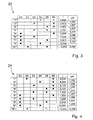
- Circuit diagrams 24 are shown, each having a relationship between the individual gear stages for forward travel "1 ° to” 8 “or” 1 "to” 9 "and a reverse gear” R1 "of the transmission 1 according to Fig. 1 and the switching states of the switching elements S1 to S6 play.
- the circuit diagrams 24 are constructed in the form of a table in whose head gaps the individual gear steps "1 ° to” 8 "or” 1 "to” 9 “and” R1 "of the transmission 1 are listed individual shift elements S1 to S6, a total ratio i_ges of the transmission 1 and a step jump phi, each of which is formed from a quotient of the values of two successive overall translations, listed.
- FIG. 1 illustrated schematic diagram of the transmission 1 shows, for example, that to set the first gear ratio "1" or the first overall gear ratio i_ges of the transmission 1, the switching elements S4 and S6 are closed or switched on.
- a drive torque from the transmission input shaft 7 via the spur gears 14 and 11 on the countershaft 10 and the spur gears 13 and 16 is guided on the sun gear 23 of the second minus planetary set 5B. It is then forwarded to the transmission output shaft 8.
- the partial ratio i1 of the power branch P1 is presently formed by the intermeshing spur gears 14 and 11 with a partial ratio ik and a translation of the spur gears 16 and 13.
- the set total ratio i_ges in the first gear "1" of the transmission 1 has due to the closed via the switching element S4 rotatably held sun gear 23 of the second minus planetary gear set 5B and the adjusting ratio in the planetary gear 5 to the value of 6.696.
- the switching element S6 In an upshift, starting from the first gear “1" in the second gear “2" of the transmission 1, the switching element S6 remains closed and the switching element S3 is switched on, at the same time the switching element S4 is switched off or opened.
- the connection of the switching element S3 causes the planetary gear set 5 is locked or blocked, that the elements of the planetary gear set are no longer mutually rotatable and the planetary gear 5 rotates as a structural unit to the bearing losses almost lossless in the housing 6.
- the partial ratio i1 of the switched power branch P1 is in turn formed from the ratio ik and the ratio between the spur gears 13 and 16, wherein due to the locked planetary gear set 5, a total ratio i_ges of 3.973 sets. This results between the first gear “1" and the second gear “2" of the transmission 1, a step jump phi of 1.685.
- the partial ratio i2 of the power branch P2 is thus composed of the translation ik and the translation, which is the ratio of the number of teeth of the spur gears 12 and 15 together.
- the partial ratio i1 of the power branch P1 is composed of the ratio ik and the ratio between the spur gears 14 and 11.
- a total ratio i_ges of the gear ratio "3" of 2.602 results.
- the incremental phi between the second gear "2" and the third gear "3" is 1.527.
- the switching element S1 and the switching element S6 is closed, so that the transmission input torque is passed through the power paths P1 and P3 via a power split by the transmission 1 and in the planetary gear 6, then is not blocked, summed on the transmission output shaft 8 is performed.
- the switching element S1 and the same time the switching element S3 is closed, so that a transmission input torque of the transmission input shaft 7 by means of the switching element S1 via the power branch P3 on the shaft 4 of Planetary gear 5 is guided.
- the closed switching element S3 in turn causes the planetary gear set 5 is blocked and the transmission input torque of the transmission input shaft 7 directly, ie with a total ratio i_ges equal to 1.0, and almost lossless through the transmission 1 to the transmission output shaft 8 is performed. It follows that in this case the partial ratio i3 of the power branch P3 has the value 1.
- the transmission according to the invention is characterized by a better efficiency due to the power split compared to known from the prior art transmissions in standard design, since the drive torque at several gear ratios of the transmission directly through the transmission, d. H. with blocked planetary gear set 5, is transmitted to the transmission output shaft 8.
- the progressive grading of the individual overall ratios of the transmission 1 offers a better possibility of adapting the traction power supply to the traction requirement as is the case with geometrically stepped transmissions, since conventional group transmissions usually have the same size gear jumps due to their geometrically stepped structure.
- the switching elements S1 to S6 of the transmission 1 are in the present case designed as known per se synchronizations, which are designed to compensate for differential speeds in the transmission with a frictional clutch or brake component. After the synchronization process, the components of the power branches or of the transmission 1 to be connected to one another in a rotationally fixed manner are positively coupled via a positive coupling or brake component of the switching elements S1 to S6.
- the switching elements S1 to S6 are designed as frictional switching elements, such as multi-plate clutches or disc brakes, wherein the transmission 1 is then designed as a power shift transmission with the Upshifts and downshifts under load, d. H. without interruption of traction, can be performed.
- the switching elements can be arranged before or after the respective transmission stage, which in the present case are designed as spur gear stages and which are switched on or off via the switching elements.
- a starting element in a drive train of a vehicle or a motor vehicle, a starting element is provided, wherein the starting of one of the load switching elements designed as switching elements of the transmission or a separate component, such as a hydrodynamic torque converter, a dry clutch or can be operatively connected to any shaft of the multi-speed transmission electric motor.
- the starting element as an electric motor required for starting drive torque is either generated by the electric motor, or a pending from a prime mover drive torque is supported by the electric motor such that at the output of a vehicle, the required for starting drive torque is applied.
- the three power paths P1 to P3 are each implemented with three partial transmissions instead of the partial transmissions i1 to i3, which have multiple partial transmission ratios and can be represented in each of the power branches P1 to P3, the number of gear stages that can be represented by the transmission 1 can be greatly expanded.
- the partial transmission ratios in the individual partial transmissions can be prepared and loaded without load before connecting the respective power branch, so that the setting of the various partial transmission ratios in the partial transmissions can be carried out with cost-effective and space-saving positive switching elements.
- connection of the power branches in the power flow of the transmission according to the invention is advantageously independent of load-shift frictional shift elements, such as multi-plate clutches, under load without interruption of traction feasible.
- the countershaft transmission portion of the transmission can be designed with at least two identical parallel to the main shaft arranged in the housing countershafts, whereby the transmission can be made even smaller, lighter and more cost effective.
Landscapes
- Engineering & Computer Science (AREA)
- General Engineering & Computer Science (AREA)
- Mechanical Engineering (AREA)
- Structure Of Transmissions (AREA)
- Transmission Devices (AREA)
Abstract
Description
Die Erfindung betrifft ein Getriebe, insbesondere ein automatisiertes leistungsverzweigtes Mehrganggetriebe, mit wenigstens drei Leistungszweigen.The invention relates to a transmission, in particular an automated power-split multi-speed transmission, with at least three power branches.
Aus der Praxis allgemein bekannte automatisierte Schaltgetriebe basieren vorwiegend auf dem Prinzip herkömmlicher Handschaltgetriebe in Vorgelegebauweise, bei welchen eine Schaltung mit Hilfe von als Synchronisierungen ausgeführten Schaltelementen erfolgt, welche durch einen geringen Bauraumbedarf gekennzeichnet sind. Im Gegensatz dazu weisen die leistungsbestimmenden Elemente eines Vorgelegegetriebes, die aufgrund ihrer hohen Lebensdauer und ihres hohen Wirkungsgrades meist als Stirnradstufen ausgeführt sind, einen großen Bauraumbedarf auf, der insbesondere bei Personenkraftwagen oftmals nur begrenzt zur Verfügung steht.From the practice well-known automated manual transmission based mainly on the principle of conventional manual transmission in countershaft design, in which a circuit with the aid of executed as synchronizing switching elements, which are characterized by a low space requirement. In contrast, the performance-determining elements of a countershaft gear, which are usually designed as a spur gear due to their high durability and high efficiency, a large space requirement, which is often limited, especially in passenger cars available.
Getriebekonzepte, welche wesentlich kompakter ausgeführt sind, stellen sogenannte Lastschaltautomatgetriebe mit Planetensätzen dar, die zusätzlich mit einer internen Leistungsverzweigung ausgeführt sein können. Wenngleich diese Getriebe aufgrund ihrer kompakten Bauweise einen relativ geringen Bauraum beanspruchen, so ist bei dieser Getriebeart jedoch nachteilig, daß die Schaltelemente, wie reibschlüssige Kupplungen und reibschlüssige Bremsen, verhältnismäßig groß dimensioniert werden müssen und hydraulisch betätigt werden. Daraus ergeben sich erhebliche Schleppverluste und eine entsprechend große Betätigungsenergie, was sich negativ auf den Wirkungsgrad des Getriebes auswirkt.Transmission concepts, which are designed to be much more compact, represent so-called powershift transmissions with planetary gear sets, which can also be designed with an internal power split. Although these transmissions require a relatively small space because of their compact design, it is disadvantageous in this type of transmission that the switching elements, such as friction clutches and friction brakes, must be relatively large and hydraulically operated. This results in significant drag losses and a correspondingly large actuation energy, which has a negative effect on the efficiency of the transmission.
Des weiteren sind aus der Praxis Getriebetypen bekannt, welche versuchen, die Vorteile der Vorgelegegetriebe hinsichtlich der kleinen Schaltelemente und die Vorteile der Lastschaltautomatgetriebe mit Planetensätzen hinsichtlich der kompakten Verzahnungen miteinander zu verbinden, indem bei einem Vorgelegegetriebe ein Planetennachschaltsatz vorgesehen wird, wobei dann ein Gruppengetriebe mit rein geometrischer Stufung vorliegt. Problematisch ist hierbei u. a., daß die Stufung bei niedrigeren Gängen sehr gering ist, während sie bei höheren Gängen sehr groß ist, was die Fahrbarkeit für Personenkraftwagen erschwert.Furthermore, from the practice gear types are known which try to combine the advantages of the countershaft transmission with respect to the small switching elements and the advantages of powershift transmissions with planetary gear sets with respect to the compact gears by a planetary gear set is provided at a countershaft transmission, in which case a group transmission with pure geometric gradation is present. The problem here is u. a. That the grading is very low at lower gears, while it is very large at higher gears, which complicates the drivability of passenger cars.
Eine Kombination von Merkmalen der vorbeschriebenen Getriebetypen zeigt ein in der
Nachteilig ist es hierbei jedoch, daß die Lastschaltung die Verwendung von Lamellenkupplungen mit einem entsprechend großen Aufwand bezüglich der Konstruktion, der hydraulischen Steuerung und der Regelung erfordert und der Bauraumbedarf des Getriebes in Bezug auf die mit dem Getriebe darstellbaren Gänge nicht optimiert ist.The disadvantage here, however, that the load circuit requires the use of multi-plate clutches with a correspondingly large effort in terms of design, hydraulic control and regulation and the space requirement of the transmission is not optimized with respect to the presentable with the transmission gears.
Aus der
Der vorliegenden Erfindung liegt daher die Aufgabe zugrunde, ein Getriebe, insbesondere ein automatisiertes leistungsverzweigtes Mehrganggetriebe, zur Verfügung zu stellen, welches gegenüber dem aufgezeigten Stand der Technik dahingehend verbessert ist, daß es auch bei einer höheren Anzahl an zu schaltenden Gängen konstruktiv kompakt und möglichst einfach mit geringem Bauraumbedarf ausführbar ist sowie durch eine gute Fahrbarkeit gekennzeichnet ist.The present invention is therefore an object of the invention to provide a transmission, in particular an automated power-split multi-speed transmission available, which is improved over the cited prior art to the effect that it is structurally compact and as simple as possible even with a higher number of gears to be switched is executable with little space requirements and is characterized by a good driveability.
Diese Aufgabe wird mit einem Getriebe gemäß den Merkmalen des Patentanspruches 1 gelöst.This object is achieved with a transmission according to the features of
Mit dem Getriebe nach der Erfindung, welches vorzugsweise in Vorgelegebauweise und mit Leistungsverzweigung sowie mit mindestens drei mit jeweils wenigstens einem Schaltelement und jeweils wenigstens einer Teilübersetzung ausgebildeten Leistungszweigen und dem Planetenradsatz ausgebildet ist, ist eine leichte und angenehme Schaltbarkeit eines Getriebe einstellbar, da ein derartiges Getriebe, insbesondere mit den kennzeichnenden Merkmalen des Patentanspruchs 1, mit der dafür erforderlichen Getriebestufung ausführbar ist.With the transmission according to the invention, which is preferably formed in Vorgelegebauweise and with power split and with at least three trained each with at least one switching element and at least one partial transmission power branches and the planetary, a light and pleasant switchability of a transmission is adjustable, since such a transmission , in particular with the characterizing features of the
Des weiteren ergibt sich aus der erfindungsgemäßen Kombination mit den jeweils in einem Leistungszweig angeordneten Teilübersetzungen und dem Planetensatz vorteilhafterweise die Möglichkeit, das Mehrganggetriebe mit möglichst vielen Gangstufen auszuführen, die wiederum mit möglichst wenigen Getriebebauteilen realisiert werden.Furthermore, it follows from the inventive combination with each arranged in a power branch part ratios and the planetary gear set advantageously the possibility to run the multi-speed transmission with as many gear ratios, which in turn are realized with as few transmission components.
Dies führt vorteilhafterweise dazu, daß das Getriebe nach der Erfindung im Vergleich zu herkömmlich ausgestalteten Mehrganggetrieben kleinere äußere Abmessungen aufweist und durch ein geringeres Gesamtgewicht gekennzeichnet ist, weshalb sich bei der Verwendung des Mehrganggetriebes in einem Kraftfahrzeug vorteilhafterweise eine Kraftstoffersparnis ergibt.This advantageously leads to the fact that the transmission according to the invention in comparison to conventionally designed multi-speed transmissions has smaller external dimensions and is characterized by a lower total weight, which is why when using the multi-speed transmission in a motor vehicle advantageously results in fuel savings.
Darüber hinaus ist von Vorteil, daß bei Einfachschaltungen in dem Mehrganggetriebe im wesentlichen jeweils immer nur ein abgeschaltetes Schaltelement zugeschaltet wird und ein zugeschaltetes Schaltelement aus dem Leistungsfluß des Getriebes nach der Erfindung abgeschaltet wird, wodurch schaltqualitätskritische Gruppenschaltungen, bei denen mehrere Schaltelemente eines Getriebes gleichzeitig betätigt werden müssen, nahezu gänzlich vermieden werden.Moreover, it is advantageous that in single gears in the multi-speed transmission essentially only one switched off switching element is switched on and a switched switching element is switched off from the power flow of the transmission according to the invention, whereby switching quality critical group circuits in which a plurality of switching elements of a transmission are operated simultaneously must be avoided, almost completely.
Zusätzlich weist das Getriebe nach der Erfindung gegenüber den aus dem Stand der Technik bekannten Getrieben den Vorteil auf, daß mit dem Getriebe wenigstens ein Gang bzw. eine Gesamtübersetzung darstellbar ist, bei der das Antriebsmoment direkt durch das Getriebe, d. h. ohne Verluste in den Verzahnungen des Getriebes, führbar ist.In addition, the transmission according to the invention over the known from the prior art transmissions on the advantage that at least one gear or a total ratio can be displayed with the transmission, in which the Drive torque directly through the transmission, ie without losses in the gears of the transmission, is feasible.
Dies wird dadurch erreicht, dass gemäß Patentanspruch 1 zwischen zwei Wellen des Planetenradsatzes ein zusätzliches Schaltelement angeordnet ist, das in geschlossenem Zustand ein Verblocken des Planetenradsatzes bewirkt.This is achieved in that according to
Darüber hinaus wird mit der erfindungsgemäßen Anordnung des zusätzlichen Schaltelementes sowie mit der erfindungsgemäßen Anordnung der anderen Schaltelemente nach Patentanspruch 1 erreicht, daß im Vergleich zu aus dem Stand der Technik bekannten Getrieben mehr Gangstufen ohne zusätzliche Zahnradstufen darstellbar sind, so daß eine Anzahl der möglichen schaltbaren Gangstufen, vorzugsweise 8 oder 9 Gangstufen, in Bezug auf den Bauraumbedarf des Getriebes gemäß der Erfindung optimiert ist.In addition, it is achieved with the inventive arrangement of the additional switching element and the inventive arrangement of the other switching elements according to
Weitere Vorteile und vorteilhafte Ausgestaltungen eines erfindungsgemäßen Getriebes sind der Beschreibung, der Zeichnung und den Patentansprüchen entnehmbar.Further advantages and advantageous embodiments of a transmission according to the invention are the description, the drawings and the claims removed.
Ein Ausführungsbeispiel eines Getriebes gemäß der Erfindung ist in der Zeichnung schematisch vereinfacht dargestellt und wird in der nachfolgenden Beschreibung näher erläutert.An embodiment of a transmission according to the invention is shown schematically simplified in the drawing and will be explained in more detail in the following description.
Es zeigt:
- Fig.1
- ein Prinzipschema eines erfindungsgemäßen Ge- triebes;
- Fig.2
- ein Räderschema des in
Fig. 1 prinzipmäßig dargestellten Getriebes; - Fig.3
- ein Schaltschema und eine Übersetzungsreihe für ein als 8-Gang-Getriebe ausgeführtes Ge- triebe gemäß der Erfindung und
- Fig.4
- ein Schaltschema und eine Übersetzungsreihe für ein als 9-Gang-Getriebe ausgeführtes Ge- triebe gemäß der Erfindung.
- Fig.1
- a schematic diagram of a transmission according to the invention;
- Fig.2
- a wheel scheme of in
Fig. 1 illustrated in principle gear; - Figure 3
- a circuit diagram and a gear train for a gear designed as 8-speed transmission according to the invention and
- Figure 4
- a circuit diagram and a gear train for a gear designed as a 9-speed transmission according to the invention.
Bezug nehmend auf
Zusätzlich sind die beiden Wellen 3 und 4 des Planetenradsatzes 5 jeweils über ein Schaltelement S4 und S2 gegenüber einem Gehäuse 6 des Getriebes 1 abstützbar bzw. nicht drehbar in dem Gehäuse 6 des Getriebes 1 festlegbar.In addition, the two
Darüber hinaus ist zwischen den beiden Wellen 3 und 4 des Planetenradsatzes 5 ein Schaltelement S3 angeordnet, welches in geschlossenem Zustand ein Verblocken des Planetenradsatzes 5 bewirkt, so daß ein über eine Getriebeeingangswelle 7 anstehendes Antriebsmoment bei geschlossenem Schaltelement S2 und bei geschlossenem Schaltelement S3 direkt mit einer Gesamtübersetzung i_ges = 1 auf eine Getriebeausgangswelle 8 führbar ist.In addition, between the two
Mit den drei vorgegebenen Übersetzungen i1, i2 und i3 und den Schaltelementen S1 bis S6 können vorzugsweise wie in den Schaltschemata 24 gemäß
In
Das Stirnrad 14 ist mit der Getriebeeingangswelle 7 drehfest verbunden und treibt während des Betriebs des Getriebes 1 die Vorgelegewelle 10 permanent an. Des weiteren ist die Getriebeeingangswelle 7 in geschlossenem Zustand des Schaltelementes S1 mit der Hauptwelle 9 des Getriebes 1 verbunden.The
Der Planetenradsatz 5 ist vorliegend als ein 4-Wellen-Planetensatz ausgeführt, der aus zwei Minusplanetensätzen 5A und 5B gebildet ist. Ein Steg 17 des ersten Minusplanetensatzes 5A ist mit einem Hohlrad 18 des zweiten Minusplanetensatzes 5B verbunden. Ein Steg 19 des zweiten Minusplanetensatzes 5B ist mit einem Hohlrad 20 des ersten Minusplanetensatzes 5A und der Getriebeausgangswelle 8 verbunden.The
Alternativ zu der letztgenannten Ausführung des Planetenradsatzes kann es bei einer weiteren Ausführung des Getriebes nach der Erfindung auch vorgesehen sein, daß der Planetenradsatz aus zwei anderen Planetensätzen kombiniert ist. Dabei kann der Planetenradsatz beispielsweise als ein Ravigneaux-Planetensatz ausgeführt sein.Alternatively to the latter embodiment of the planetary gear set, it may also be provided in a further embodiment of the transmission according to the invention that the planetary gear set is combined from two other planetary gear sets. In this case, the planetary gear set may for example be designed as a Ravigneaux planetary gear set.
Die Hauptwelle 9, welche mit dem Steg 17 des ersten Minusplanetensatzes 5A verbunden ist, ist in geschlossenem Zustand des Schaltelementes S2 mit dem Gehäuse 6 des Getriebes 1 derart verbunden, daß die Hauptwelle 9 und damit auch der Steg bzw. der Planetenträger 17 des ersten Minusplanetensatzes 5A drehfest in dem Gehäuse 6 angeordnet sind.The
Im geschlossenen Zustand des Schaltelementes S3 ist die Hauptwelle 9 über eine Hohlwelle 21 mit einem Sonnenrad 22 des ersten Minusplanetensatzes 5A verbunden, so daß das Sonnenrad 22 und der Steg 17 des ersten Minusplanetensatzes 5A nicht drehbar miteinander verbunden sind und der Planetenradsatz 5 verblockt ist und als starre Einheit umläuft.In the closed state of the switching element S3, the
In geschlossenem Zustand des Schaltelementes S4 ist die Hohlwelle 21 und damit das Sonnenrad 22 des ersten Minusplanetensatzes 5A fest mit dem Gehäuse 6 verbunden, wobei bei geschlossenem Schaltelement S5 die Übersetzung, welche durch die miteinander kämmenden Stirnräder 12 und 15 gebildet wird, in den Leistungsfluß des Getriebes 1 zugeschaltet ist.In the closed state of the switching element S4, the
Über das Schaltelement S6 wird eine weitere Stirnradstufe, welche durch die miteinander in Eingriff stehenden Stirnrädern 13 und 16 gebildet ist, in den Leistungsfluß des Getriebes 1 zugeschaltet. D. h., daß in geschlossenem Zustand des Schaltelementes S6 das über die Vorgelegewelle 10 anstehende Antriebsmoment auf ein Sonnenrad 23 des zweiten Minusplanetensatzes 5B weitergeleitet wird.About the switching element S6, a further spur gear, which is formed by the mutually engaged
Bei entsprechender Ansteuerung der Schaltelemente S1 bis S6 wird ein Getriebeeingangsmoment auf einem der Leistungszweige P1, P2 oder P3 oder bei eingestellter Leistungsverzweigung gleichzeitig über zwei der drei Leistungszweige P1 bis P3 geführt. Jeder der Leistungszweige P1 bis P3 wird mit Hilfe des ihm zugeordneten Schaltelementes S6, S5 oder S1 mit seiner Teilübersetzung i1, i2 oder i3 in einen Leistungsfluß des Getriebes 1 bedarfsweise zugeschaltet bzw. aus diesem abgeschaltet.With appropriate control of the switching elements S1 to S6 a transmission input torque is performed on one of the power branches P1, P2 or P3 or at set power split simultaneously over two of the three power branches P1 to P3. Each of the power branches P1 to P3 is with the help of its associated switching element S6, S5 or S1 with its partial translation i1, i2 or i3 switched into a power flow of the
Die vorliegend jeweils mit einer Teilübersetzung ausgeführten Leistungspfade P1 bis P3 können in einer Weiterbildung der Erfindung auch mit Teilgetrieben ausgeführt sein, die jeweils mehr als eine Teilübersetzung aufweisen.The present in each case carried out with a partial translation performance paths P1 to P3 can be carried out in a development of the invention with partial transmissions, each having more than a partial translation.
Mit der vorbeschriebenen erfindungsgemäßen Ausführung des Getriebes sind in Kombination mit der nachfolgend beschriebenen Schaltlogik viele Gangstufen bzw. Gesamtübersetzungen des Getriebes 1 bei einer gleichzeitig geringen Anzahl an Übersetzungsstufen einstellbar, so daß ein sehr bauraumgünstiges Getriebekonzept gegeben ist.With the above-described embodiment of the transmission according to the invention in combination with the switching logic described below many gear ratios or overall ratios of the
In
Die Schaltschemata 24 sind in Form einer Tabelle aufgebaut, in deren Kopfspalte die einzelnen Gangstufen "1° bis "8" bzw. "1" bis "9" und "R1" des Getriebes 1 aufgeführt sind. In der Kopfzeile der Schaltschemata 24 sind die einzelnen Schaltelemente S1 bis S6, eine Gesamtübersetzung i_ges des Getriebes 1 und ein Stufensprung phi, der jeweils aus einem Quotient aus den Werten zweier aufeinanderfolgender Gesamtübersetzungen gebildet ist, aufgeführt.The circuit diagrams 24 are constructed in the form of a table in whose head gaps the individual gear steps "1 ° to" 8 "or" 1 "to" 9 "and" R1 "of the
Aus dem Schaltschema 24 gemäß
In diesem Schaltzustand des Getriebes 1 wird das Antriebsmoment der Getriebeeingangswelle 7 über den in
Die Teilübersetzung i1 des Leistungszweiges P1 wird vorliegend durch die miteinander kämmenden Stirnräder 14 und 11 mit einer Teilübersetzung ik und einer Übersetzung der Stirnräder 16 und 13 gebildet. Die eingestellte Gesamtübersetzung i_ges in der ersten Gangstufe "1" des Getriebes 1 weist aufgrund des über das geschlossene Schaltelement S4 drehfest gehaltenen Sonnenrads 23 des zweiten Minusplanetensatzes 5B und der sich einstellenden Übersetzung in dem Planetenradsatz 5 den Wert 6,696 auf.The partial ratio i1 of the power branch P1 is presently formed by the intermeshing spur gears 14 and 11 with a partial ratio ik and a translation of the spur gears 16 and 13. The set total ratio i_ges in the first gear "1" of the
Bei einer Hochschaltung, ausgehend von der ersten Gangstufe "1" in die zweite Gangstufe "2" des Getriebes 1, bleibt das Schaltelement S6 geschlossen und das Schaltelement S3 wird zugeschaltet, wobei gleichzeitig das Schaltelement S4 abgeschaltet bzw. geöffnet wird. Die Zuschaltung des Schaltelementes S3 bewirkt, daß der Planetenradsatz 5 gesperrt bzw. verblockt wird, daß die Elemente des Planetenradsatzes nicht mehr gegeneinander drehbar sind und der Planetenradsatz 5 als bauliche Einheit bis auf die Lagerverluste nahezu verlustfrei im Gehäuse 6 umläuft.In an upshift, starting from the first gear "1" in the second gear "2" of the
In geschlossenem Zustand des Schaltelementes S3 ist die Welle 3 und die Welle 4 des Getriebes 1, welche in
Die Teilübersetzung i1 des zugeschalteten Leistungszweiges P1 wird wiederum aus der Übersetzung ik und der Übersetzung zwischen den Stirnrädern 13 und 16 gebildet, wobei sich aufgrund des gesperrten Planetenradsatzes 5 eine Gesamtübersetzung i_ges von 3,973 einstellt. Damit ergibt sich zwischen der ersten Gangstufe "1" und der zweiten Gangstufe "2" des Getriebes 1 ein Stufensprung phi von 1,685.The partial ratio i1 of the switched power branch P1 is in turn formed from the ratio ik and the ratio between the spur gears 13 and 16, wherein due to the locked planetary gear set 5, a total ratio i_ges of 3.973 sets. This results between the first gear "1" and the second gear "2" of the
Zur Einstellung des Rückwärtsganges "R1" wird wie in den Schaltschemata 24 gemäß
Bei einer Hochschaltung, ausgehend von der zweiten Gangstufe "2" in die dritte Gangstufe "3" des Getriebes 1, bleibt das Schaltelement S6 wiederum geschlossen und das Schaltelement S5 wird in den Leistungsfluß des Getriebes 1 zugeschaltet. Gleichzeitig wird das Schaltelement S3 abgeschaltet. Damit wird das Antriebsmoment der Getriebeeingangswelle 7 über die beiden Leistungszweige P1 und P2 mit deren Teilübersetzungen i1 und i2 leistungsverzweigt durch das Getriebe 1 geführt, wobei das aufgeteilte Antriebsmoment im Planetenradsatz 5 aufsummiert wird und anschließend auf die Getriebeausgangswelle 8 weitergeleitet wird.In an upshift, starting from the second gear "2" in the third gear "3" of the
In diesem Betriebszustand des Getriebes 1 wird das Getriebeeingangsmoment über die Stirnräder 14 und 11 mit der Übersetzung ik auf die Vorgelegewelle und von dort aus über die Stirnräder 12 und 15 und deren Übersetzung auf das Sonnenrad 22 des ersten Minusplanetensatzes 5A geführt. Gleichzeitig wird ein Teil des Antriebsmomentes von der Vorgelegewelle 10 über die Stirnräder 13 und 16 und deren Übersetzung auf das Sonnenrad 23 des zweiten Minusplanetensatzes 5B geführt. Im Planetenradsatz 5 werden die beiden Teile des Antriebsmomentes aufsummiert und auf die Getriebeausgangswelle 8 aufgegeben.In this operating state of the
Die Teilübersetzung i2 des Leistungszweiges P2 setzt sich damit aus der Übersetzung ik und der Übersetzung, welche sich aus dem Verhältnis der Zähnezahlen der Stirnräder 12 und 15 ergibt, zusammen. Die Teilübersetzung i1 des Leistungszweiges P1 setzt sich aus der Übersetzung ik und der Übersetzung zwischen den Stirnrädern 14 und 11 zusammen. In diesem Schaltzustand des Getriebes 1 ergibt sich eine Gesamtübersetzung i_ges der Gangstufe "3" von 2,602. Der Stufensprung phi zwischen der zweiten Gangstufe "2" und der dritten Gangstufe "3" ist dabei 1,527.The partial ratio i2 of the power branch P2 is thus composed of the translation ik and the translation, which is the ratio of the number of teeth of the spur gears 12 and 15 together. The partial ratio i1 of the power branch P1 is composed of the ratio ik and the ratio between the spur gears 14 and 11. In this switching state of the
Bei einer weiteren Hochschaltung von der dritten Gangstufe "3" in die vierte Gangstufe "4" wird das Schaltelement S6 abgeschaltet und das Schaltelement S3 geschlossen, so daß das Getriebeeingangsmoment über den Leistungszweig P2 und den verblockten Planetenradsatz 5 auf die Getriebeausgangswelle 8 geführt wird, so daß einerseits keine Leistungsverzweigung im Getriebe 1 vorliegt und eine Verlustleistung im Planetenradsatz 5 aufgrund des direkten Durchtriebes des Getriebeeingangsmomentes mit der Teilübersetzung i2, welche dann auch gleichzeitig die Gesamtübersetzung i_ges darstellt, vermieden wird.In a further upshift from the third gear "3" in the fourth gear "4", the switching element S6 is turned off and the switching element S3 is closed, so that the transmission input torque on the power branch P2 and the interlocked
Ist die fünfte Gangstufe "5" in dem Getriebe 1 eingelegt, dann ist das Schaltelement S1 sowie das Schaltelement S6 geschlossen, so daß das Getriebeeingangsmoment über die Leistungspfade P1 und P3 über eine Leistungsverzweigung durch das Getriebe 1 geführt wird und im Planetenradsatz 6, der dann nicht verblockt ist, aufsummiert auf die Getriebeausgangswelle 8 geführt wird.If the fifth gear "5" is inserted in the
Um die sechste Gangstufe "6" in dem Getriebe 1 darzustellen, ist das Schaltelement S1 und gleichzeitig das Schaltelement S3 geschlossen, so daß ein Getriebeeingangsmoment der Getriebeeingangswelle 7 mittels des Schaltelementes S1 über den Leistungszweig P3 auf die Welle 4 des Planetenradsatzes 5 geführt wird. Das geschlossene Schaltelement S3 führt wiederum dazu, daß der Planetenradsatz 5 verblockt ist und das Getriebeeingangsmoment von der Getriebeeingangswelle 7 direkt, d. h. mit einer Gesamtübersetzung i_ges gleich 1,0, und nahezu verlustfrei durch das Getriebe 1 auf die Getriebeausgangswelle 8 geführt wird. Daraus folgt, daß die Teilübersetzung i3 des Leistungszweiges P3 vorliegend den Wert 1 aufweist.To represent the sixth gear "6" in the
Die vorbeschriebene Schaltlogik und die damit verbundene wechselweise Führung des Antriebsmomentes über jeweils einen oder gleichzeitig über zwei der drei Leistungszweige mit den verschiedenen Teilübersetzungen in Kombination mit dem zusätzlichen Schaltelement zum Verblocken des Planetenradsatzes 5 führt im Vergleich zu aus dem Stand der Technik bekannten Getrieben dazu, daß die gleiche Anzahl an Gangstufen mit weniger Radebenen darstellbar ist. Somit weist das Getriebe gemäß der Erfindung bei gleicher Leistungsfähigkeit wesentlich kleinere äußere Abmessungen, ein damit einhergehend geringeres Gesamtgewicht und darüber hinaus wesentlich niedrigere Herstellkosten auf.The above-described switching logic and the associated alternately guiding the drive torque via one or simultaneously over two of the three power branches with the different partial ratios in combination with the additional switching element for blocking the
Des weiteren ist das Getriebe nach der Erfindung aufgrund der Leistungsverzweigung gegenüber aus dem Stand der Technik bekannten Getrieben in Standardbauweise durch einen besseren Wirkungsgrad gekennzeichnet, da das Antriebsmoment bei mehreren Gangstufen des Getriebes direkt durch das Getriebe, d. h. mit verblocktem Planetenradsatz 5, auf die Getriebeausgangswelle 8 übertragen wird.Furthermore, the transmission according to the invention is characterized by a better efficiency due to the power split compared to known from the prior art transmissions in standard design, since the drive torque at several gear ratios of the transmission directly through the transmission, d. H. with blocked planetary gear set 5, is transmitted to the
Des weiteren bietet die progressive Stufung der einzelnen Gesamtübersetzungen des Getriebes 1 eine bessere Möglichkeit der Anpassung des Zugkraftangebotes an den Zugkraftbedarf als dies bei geometrisch gestuften Getrieben der Fall ist, da herkömmliche Gruppengetriebe in der Regel aufgrund ihres geometrisch gestuften Aufbaus gleich große Gangsprünge aufweisen.Furthermore, the progressive grading of the individual overall ratios of the
Die Schaltelemente S1 bis S6 des Getriebes 1 sind vorliegend als an sich bekannte Synchronisierungen ausgeführt, die zum Ausgleich von Differenzdrehzahlen im Getriebe mit einer reibschlüssigen Kupplungs- bzw. Bremskomponente ausgeführt sind. Nach dem Synchronisiervorgang werden die miteinander drehfest zu verbindenden Bauteile der Leistungszweige bzw. des Getriebes 1 über eine formschlüssige Kupplungs- bzw. Bremskomponente der Schaltelemente S1 bis S6 formschlüssig gekoppelt.The switching elements S1 to S6 of the
Alternativ hierzu kann es bei einer weiteren vorteilhaften Ausführungsform des Getriebes nach der Erfindung selbstverständlich auch vorgesehen sein, daß die Schaltelemente S1 bis S6 als reibschlüssige Schaltelemente, wie beispielsweise Lamellenkupplungen oder Lamellenbremsen, ausgeführt sind, wobei das Getriebe 1 dann als Lastschaltgetriebe ausgeführt ist, mit dem Hoch- und Rückschaltungen unter Last, d. h. ohne Zugkraftunterbrechung, ausgeführt werden können.Alternatively, it may of course also be provided in a further advantageous embodiment of the transmission according to the invention, that the switching elements S1 to S6 are designed as frictional switching elements, such as multi-plate clutches or disc brakes, wherein the
Die Schaltelemente können vor oder nach der jeweiligen Übersetzungsstufe, die vorliegend als Stirnradstufen ausgeführt sind und die über die Schaltelemente zu- bzw. abgeschaltet werden, angeordnet werden. Je näher die Schaltelemente an den zuzuschaltenden Übersetzungsstufen positioniert sind, desto kleiner sind die jeweils über die Schaltelemente zu synchronisierenden Drehmassen der an einer Schaltung beteiligten Getriebebauteile.The switching elements can be arranged before or after the respective transmission stage, which in the present case are designed as spur gear stages and which are switched on or off via the switching elements. The closer the switching elements are positioned to the zuzuschaltenden translation stages, the smaller are the respective rotational elements to be synchronized via the switching elements of the transmission components involved in a circuit.
Zusätzlich kann es bei einer weiteren vorteilhaften Weiterbildung des Getriebes nach der Erfindung vorgesehen sein, daß in einem Antriebsstrang eines Fahrzeugs bzw. eines Kraftfahrzeugs ein Anfahrelement vorgesehen ist, wobei das Anfahrelement eines der als Lastschaltelemente ausgeführten Schaltelemente des Getriebes oder ein separates Bauteil, wie beispielsweise ein hydrodynamischer Drehmomentwandler, eine Trockenkupplung oder ein mit einer beliebigen Welle des Mehrganggetriebes wirkverbundener Elektromotor sein kann.In addition, it may be provided in a further advantageous embodiment of the transmission according to the invention that in a drive train of a vehicle or a motor vehicle, a starting element is provided, wherein the starting of one of the load switching elements designed as switching elements of the transmission or a separate component, such as a hydrodynamic torque converter, a dry clutch or can be operatively connected to any shaft of the multi-speed transmission electric motor.
Insbesondere bei der separaten Ausführung des Anfahrelementes als Elektromotor wird ein zum Anfahren benötigtes Antriebsmoment entweder von dem Elektromotor erzeugt, oder ein von einer Antriebsmaschine anstehendes Antriebsmoment wird von dem Elektromotor derart abgestützt, daß am Abtrieb eines Fahrzeugs das zum Anfahren erforderliche Antriebsmoment anliegt.In particular, in the separate embodiment of the starting element as an electric motor required for starting drive torque is either generated by the electric motor, or a pending from a prime mover drive torque is supported by the electric motor such that at the output of a vehicle, the required for starting drive torque is applied.
Sind die drei Leistungspfade P1 bis P3 anstatt mit den Teilübersetzungen i1 bis i3 jeweils mit drei Teilgetrieben ausgeführt, die mehrere Teilgetriebeübersetzungen aufweisen und die in jedem der Leistungszweige P1 bis P3 darstellbar sind, ist die Anzahl der mit dem Getriebe 1 darstellbaren Gangstufen stark erweiterbar. Dabei können die Teilgetriebeübersetzungen in den einzelnen Teilgetrieben vor Zuschalten des jeweiligen Leistungszweiges lastfrei vorbereitet und eingelegt werden, so daß die Einstellung der verschiedenen Teilgetriebeübersetzungen in den Teilgetrieben mit kosten- und bauraumgünstigen formschlüssigen Schaltelementen durchführbar ist.If the three power paths P1 to P3 are each implemented with three partial transmissions instead of the partial transmissions i1 to i3, which have multiple partial transmission ratios and can be represented in each of the power branches P1 to P3, the number of gear stages that can be represented by the
Die Zuschaltung der Leistungszweige in den Leistungsfluß des erfindungsgemäßen Getriebes ist unabhängig davon vorteilhafterweise über lastschaltfähige reibschlüssige Schaltelemente, wie beispielsweise Lamellenkupplungen, unter Last ohne Zugkraftunterbrechung durchführbar.The connection of the power branches in the power flow of the transmission according to the invention is advantageously independent of load-shift frictional shift elements, such as multi-plate clutches, under load without interruption of traction feasible.
Alternativ zu der in
- 11
- Getriebetransmission
- 2-42-4
- Wellen des PlanetenradsatzesWaves of the planetary gear set
- 55
- Planetenradsatzplanetary gear
- 5A5A
- erster Minusplanetensatzfirst minus planetary set
- 5B5B
- zweiter Minusplanetensatzsecond minus planet set
- 66
- Gehäuse des GetriebesHousing of the transmission
- 77
- GetriebeeingangswelleTransmission input shaft
- 88th
- GetriebeausgangswelleTransmission output shaft
- 99
- Hauptwellemain shaft
- 1010
- VorgelegewelleCountershaft
- 11-1611-16
- Stirnräderspur gears
- 1717
- Steg des ersten MinusplanetensatzesFootbridge of the first minus planet set
- 1818
- Hohlrad des zweiten MinusplanetensatzesRing gear of the second minus planetary set
- 1919
- Steg des zweiten MinusplanetensatzesFootbridge of the second minus planet set
- 2020
- Hohlrad des ersten MinusplanetensatzesRing gear of the first minus planetary set
- 2121
- Hohlwellehollow shaft
- 2222
- Sonnenrad des ersten MinusplanetensatzesSun wheel of the first minus planet set
- 2323
- Sonnenrad des zweiten MinusplanetensatzesSun wheel of the second minus planet set
- 2424
- Schaltschemaswitching scheme
- P1-P3P1-P3
- Leistungszweigpower branch
- i1, i2,i1, i2,
- i3, iki3, ik
- Teilübersetzungpartial translation
- S1-S6S1-S6
- Schaltelementswitching element
Claims (4)
- Gearbox (1), in particular automatic power-split multi-gear gearbox, having at least three power branches (P1, P2, P3) which are connected in each case to a shaft (2, 3, 4) of a downstream planetary gear set (5) and which are formed in each case with at least one component transmission ratio (i1, i2, i3), with each of the power branches (P1, P2, P3) being formed with a shift element (S1, S5, S6) for connecting the power branches (P1 to P3) with a component transmission ratio (i1, i2, i3) into a power flow, and at least one of the shafts (3, 4) of the planetary gear set (5) being operatively connected to a further shift element (S2, S4) via which the shaft (3, 4) can be supported with respect to a housing (6), and an additional shift element (S3) being arranged between two shafts (3, 4) of the planetary gear set (5), which additional shift element (S3), when it is closed, places the planetary gear set (5) in a blocked state, wherein- a first shift element (S1) is arranged in the third power branch (P3),- a fifth shift element (S5) is arranged in the second power branch (P2) and- a sixth shift element (S6) is arranged in the first power branch (P1) and- a first shaft (4) of the planetary gear set (5) can be supported on the housing (6) via a second shift element (S2),- a second shaft (3) of the planetary gear set (5) can be supported on the housing (6) via a fourth shift element (S4), and- a third shift element (S3) is provided between the two shafts (3, 4) of the planetary gear set (5).
- Gearbox according to Claim 1, characterized in that the gearbox (1) has eight forward gears, and- to engage the first forward gear, the fourth and sixth shift elements (S4, S6) are closed,- to engage the second forward gear, the third and sixth shift elements (S3, S6) are closed,- to engage the third forward gear, the fifth and sixth shift elements (S5, S6) are closed,- to engage the fourth forward gear, the third and fifth shift elements (S3, S5) are closed,- to engage the fifth forward gear, the first and sixth shift elements (S1, S6) are closed,- to engage the sixth forward gear, the first and third shift elements (S1, S3) are closed,- to engage the seventh forward gear, the first and fifth shift elements (S1, S5) are closed, and- to engage the eighth forward gear, the first and fourth shift elements (S1, S4) are closed.
- Gearbox according to Claim 1, characterized in that the gearbox (1) has nine forward gears, and- to engage the first forward gear, the second and sixth shift elements (S2, S6) are closed,- to engage the second forward gear, the fourth and sixth shift elements (S4, S6) are closed,- to engage the third forward gear, the third and sixth shift elements (S3, S6) are closed,- to engage the fourth forward gear, the fifth and sixth shift elements (S5, S6) are closed,- to engage the fifth forward gear, the third and fifth shift elements (S3, S5) are closed,- to engage the sixth forward gear, the first and sixth shift elements (S1, S6) are closed,- to engage the seventh forward gear, the first and third shift elements (S1, S3) are closed,- to engage the eighth forward gear, the first and fifth shift elements (S1, S5) are closed, and- to engage the ninth forward gear, the first and fourth shift elements (S1, S4) are closed.
- Gearbox according to one of the preceding claims, characterized in that, to engage a reverse gear, the second and fifth shift elements (S2, S5) are closed.
Applications Claiming Priority (2)
| Application Number | Priority Date | Filing Date | Title |
|---|---|---|---|
| DE10315313A DE10315313A1 (en) | 2003-04-04 | 2003-04-04 | Transmission, in particular automated power-split multi-speed transmission |
| PCT/EP2004/003274 WO2004088174A1 (en) | 2003-04-04 | 2004-03-27 | Transmission, in particular an automated power-branched multi-speed gearing |
Publications (2)
| Publication Number | Publication Date |
|---|---|
| EP1611373A1 EP1611373A1 (en) | 2006-01-04 |
| EP1611373B1 true EP1611373B1 (en) | 2010-11-24 |
Family
ID=33103192
Family Applications (1)
| Application Number | Title | Priority Date | Filing Date |
|---|---|---|---|
| EP04723904A Expired - Lifetime EP1611373B1 (en) | 2003-04-04 | 2004-03-27 | Transmission, in particular an automated power-branched multi-speed gearing |
Country Status (6)
| Country | Link |
|---|---|
| US (1) | US7288044B2 (en) |
| EP (1) | EP1611373B1 (en) |
| JP (1) | JP4903556B2 (en) |
| CN (1) | CN100434757C (en) |
| DE (2) | DE10315313A1 (en) |
| WO (1) | WO2004088174A1 (en) |
Families Citing this family (71)
| Publication number | Priority date | Publication date | Assignee | Title |
|---|---|---|---|---|
| KR20070057973A (en) * | 2004-09-23 | 2007-06-07 | 다임러크라이슬러 아크티엔게젤샤프트 | Automated transmission for a motor vehicle and method for operating the same |
| DE102005022012A1 (en) * | 2005-05-12 | 2006-12-07 | Daimlerchrysler Ag | Transmission for a motor vehicle with stepless power-split driving ranges |
| US7364527B2 (en) * | 2005-09-23 | 2008-04-29 | General Motors Corporation | Nine speed automatic transmission with six torque-transmitting mechanisms |
| DE102005046894A1 (en) * | 2005-09-30 | 2007-05-03 | Zf Friedrichshafen Ag | Automated automotive manual transmission and method for switching control of an automated automotive manual transmission |
| US7998019B2 (en) * | 2007-09-25 | 2011-08-16 | GM Global Technology Operations LLC | Multi-speed transmission with external drive gearsets |
| US8157688B2 (en) * | 2007-09-26 | 2012-04-17 | GM Global Technology Operations LLC | Multi-speed transmission with external drive gearsets |
| US7871349B2 (en) * | 2007-11-06 | 2011-01-18 | GM Global Technology Operations LLC | Multi-speed transmission with external drive gearsets |
| CN101769364B (en) * | 2010-02-11 | 2012-05-23 | 合肥工大汽车工程技术研究院有限公司 | Vehicle dual-clutch transmission |
| US8409048B2 (en) * | 2010-10-20 | 2013-04-02 | GM Global Technology Operations LLC | Planetary layshaft transmission |
| US9347532B2 (en) | 2012-01-19 | 2016-05-24 | Dana Limited | Tilting ball variator continuously variable transmission torque vectoring device |
| EP2815152A1 (en) | 2012-02-15 | 2014-12-24 | Dana Limited | Transmission and driveline having a tilting ball variator continuously variable transmission |
| CN104769325A (en) | 2012-09-06 | 2015-07-08 | 德纳有限公司 | Transmission having a continuously or infinitely variable variator drive |
| US9052000B2 (en) | 2012-09-07 | 2015-06-09 | Dana Limited | Ball type CVT/IVT including planetary gear sets |
| CN104755812A (en) | 2012-09-07 | 2015-07-01 | 德纳有限公司 | Ivt based on a ball type cvp including powersplit paths |
| CN104769329B (en) | 2012-09-07 | 2017-06-23 | 德纳有限公司 | Ball-type continous way buncher/unlimited formula buncher |
| US9353842B2 (en) | 2012-09-07 | 2016-05-31 | Dana Limited | Ball type CVT with powersplit paths |
| US9638296B2 (en) | 2012-09-07 | 2017-05-02 | Dana Limited | Ball type CVT including a direct drive mode |
| JP6247690B2 (en) | 2012-09-07 | 2017-12-13 | デーナ リミテッド | Ball CVT with output connection power path |
| US10030748B2 (en) | 2012-11-17 | 2018-07-24 | Dana Limited | Continuously variable transmission |
| KR101339268B1 (en) * | 2012-12-18 | 2013-12-09 | 현대자동차 주식회사 | Planetary gear train of automatic transmission for vehicles |
| WO2014124063A1 (en) | 2013-02-08 | 2014-08-14 | Microsoft Corporation | Pervasive service providing device-specific updates |
| WO2014159755A2 (en) | 2013-03-14 | 2014-10-02 | Dana Limited | Ball type continuously variable transmission |
| EP2971860A4 (en) | 2013-03-14 | 2016-12-28 | Dana Ltd | Transmission with cvt and ivt variator drive |
| KR101382313B1 (en) | 2013-04-01 | 2014-04-08 | 현대자동차 주식회사 | Planetary gear train of automatic transmission for vehicles |
| JP2016520782A (en) | 2013-06-06 | 2016-07-14 | デーナ リミテッド | 3 mode front wheel drive and rear wheel drive continuously variable planetary transmission |
| US10088022B2 (en) | 2013-11-18 | 2018-10-02 | Dana Limited | Torque peak detection and control mechanism for a CVP |
| WO2015073883A1 (en) | 2013-11-18 | 2015-05-21 | Dana Limited | Infinite variable transmission with planetary gear set |
| CN106536987A (en) | 2014-06-17 | 2017-03-22 | 德纳有限公司 | Off-highway continuously variable planetary-based multimore transmission including infinite variable transmission and direct continuously variable tranmission |
| US20160040754A1 (en) | 2014-08-07 | 2016-02-11 | Allison Transmission, Inc. | Multi-speed transmission |
| US9625007B2 (en) | 2014-08-12 | 2017-04-18 | Allison Transmission, Inc. | Multi-speed transmission |
| WO2016069362A1 (en) | 2014-10-27 | 2016-05-06 | Allison Transmission, Inc. | Multi-speed transmission |
| US9726256B2 (en) | 2014-10-27 | 2017-08-08 | Allison Transmission, Inc. | Multi-speed transmission |
| US9512905B2 (en) | 2014-10-27 | 2016-12-06 | Allison Transmission, Inc. | Multi-speed transmission |
| EP3212965A4 (en) | 2014-10-27 | 2018-08-15 | Allison Transmission, Inc. | Multi-speed transmission |
| US9927009B2 (en) | 2015-04-23 | 2018-03-27 | Allison Transmission, Inc. | Multi-speed transmission |
| US9689467B2 (en) | 2015-04-24 | 2017-06-27 | Allison Transmission, Inc. | Multi-speed transmission |
| US9890835B2 (en) | 2015-04-24 | 2018-02-13 | Allison Transmission, Inc. | Multi-speed transmission |
| US10132388B2 (en) | 2015-05-15 | 2018-11-20 | Allison Transmission, Inc. | Multi-speed transmission |
| DE102015210543B4 (en) * | 2015-06-09 | 2016-12-22 | Bayerische Motoren Werke Aktiengesellschaft | Combined manual transmission |
| DE102015210542B4 (en) * | 2015-06-09 | 2020-03-12 | Bayerische Motoren Werke Aktiengesellschaft | Combined manual transmission |
| US9810287B2 (en) | 2015-06-24 | 2017-11-07 | Allison Transmission, Inc. | Multi-speed transmission |
| US9803725B2 (en) | 2015-07-13 | 2017-10-31 | Allison Transmission, Inc | Multi-speed transmission |
| EP3347622B1 (en) | 2015-09-09 | 2021-01-27 | Allison Transmission, Inc. | Multi-speed transmission |
| US10030594B2 (en) | 2015-09-18 | 2018-07-24 | Dana Limited | Abuse mode torque limiting control method for a ball-type continuously variable transmission |
| CN105443705B (en) * | 2016-01-12 | 2018-11-09 | 赵良红 | Semi-built-up gear-shift mechanism |
| DE102016217244A1 (en) * | 2016-09-09 | 2018-03-15 | Zf Friedrichshafen Ag | Transmission for a motor vehicle, and powertrain for a motor vehicle |
| US10060511B2 (en) | 2016-09-28 | 2018-08-28 | Allison Transmission, Inc. | Multi-speed planetary transmission |
| US10323723B2 (en) | 2016-09-28 | 2019-06-18 | Allison Transmission, Inc. | Multi-speed planetary transmission |
| US10302173B2 (en) | 2016-09-28 | 2019-05-28 | Allison Transmission, Inc. | Multi-speed planetary transmission |
| US9927008B1 (en) | 2016-09-28 | 2018-03-27 | Allison Transmission, Inc. | Multi-speed planetary transmission |
| US10060512B2 (en) | 2016-09-28 | 2018-08-28 | Allison Transmission, Inc. | Multi-speed planetary transmission |
| US10364867B2 (en) | 2016-09-28 | 2019-07-30 | Allison Transmission, Inc. | Multi-speed planetary transmission |
| US9869377B1 (en) | 2016-09-28 | 2018-01-16 | Allison Transmission, Inc. | Multi-speed planetary transmission |
| US10473190B2 (en) | 2016-09-28 | 2019-11-12 | Allison Transmission, Inc. | Multi-speed planetary transmission |
| US9933045B1 (en) | 2016-09-28 | 2018-04-03 | Allison Transmission, Inc. | Multi-speed planetary transmission |
| US10533644B2 (en) | 2016-09-28 | 2020-01-14 | Allison Transmission, Inc. | Multi-speed planetary transmission |
| US10072735B2 (en) | 2016-09-28 | 2018-09-11 | Allison Transmission, Inc. | Multi-speed planetary transmission |
| US10260599B2 (en) | 2016-09-28 | 2019-04-16 | Allison Transmission, Inc. | Multi-speed planetary transmission |
| US10161486B2 (en) | 2016-09-28 | 2018-12-25 | Allison Transmission, Inc. | Multi-speed planetary transmission |
| US10072736B2 (en) | 2016-09-28 | 2018-09-11 | Allison Transmission, Inc. | Multi-speed planetary transmission |
| US10161484B2 (en) | 2016-09-28 | 2018-12-25 | Allison Transmission, Inc. | Multi-speed planetary transmission |
| US10156283B2 (en) | 2016-09-28 | 2018-12-18 | Allison Transmission, Inc. | Multi-speed planetary transmission |
| US10253850B2 (en) | 2016-09-28 | 2019-04-09 | Allison Transmission, Inc. | Multi-speed planetary transmission |
| US10451147B2 (en) | 2016-09-28 | 2019-10-22 | Allison Transmission, Inc. | Multi-speed planetary transmission |
| US10234001B2 (en) | 2016-09-28 | 2019-03-19 | Allison Transmission, Inc. | Multi-speed planetary transmission |
| US10316940B2 (en) | 2016-09-28 | 2019-06-11 | Allison Transmission, Inc. | Multi-speed planetary transmission |
| US10174814B2 (en) | 2016-09-28 | 2019-01-08 | Allison Transmission, Inc. | Multi-speed planetary transmission |
| US10323722B2 (en) | 2016-09-28 | 2019-06-18 | Allison Transmission, Inc. | Multi-speed planetary transmission |
| US10619710B2 (en) | 2017-08-31 | 2020-04-14 | Allison Transmission, Inc. | Transmission including planetary gear thrust containment |
| DE102019007129B4 (en) | 2019-10-14 | 2021-09-23 | Daimler Ag | Group transmission device, in particular split transmission |
| DE102022214118A1 (en) | 2022-12-21 | 2024-06-27 | Zf Friedrichshafen Ag | Motor vehicle transmission for an at least partially electrically powered motor vehicle |
Family Cites Families (15)
| Publication number | Priority date | Publication date | Assignee | Title |
|---|---|---|---|---|
| DE2447581C3 (en) * | 1974-10-05 | 1978-08-03 | Zahnradfabrik Friedrichshafen Ag, 7990 Friedrichshafen | Planetary gear change gears, in particular for motor vehicles |
| US5013289A (en) * | 1990-02-20 | 1991-05-07 | General Motors Corporation | Power transmission |
| FR2677422B1 (en) * | 1991-06-07 | 1995-05-05 | Renault | DEVICE FOR CHANGING AUTOMATIC SPEED TRANSVERSE AT END. |
| US5567201A (en) * | 1994-10-24 | 1996-10-22 | General Motors Corporation | Five-speed transmission assembly employing compounded planetary gear sets |
| US5520587A (en) * | 1995-05-03 | 1996-05-28 | General Motors Corporation | Power transmission |
| US5520588A (en) * | 1995-05-03 | 1996-05-28 | General Motors Corporation | Power transmission |
| US5593358A (en) * | 1995-06-01 | 1997-01-14 | New Venture Gear, Inc. | Multi-speed manual transmission with two simple planetary gearsets |
| US5971883A (en) * | 1998-03-13 | 1999-10-26 | General Motors Corporation | Multi-speed power transmission |
| JP4590737B2 (en) * | 2001-01-09 | 2010-12-01 | アイシン・エィ・ダブリュ株式会社 | Automatic transmission |
| DE10145519A1 (en) * | 2001-09-14 | 2003-04-03 | Zahnradfabrik Friedrichshafen | Automated multi-speed vehicle transmission |
| JP3736481B2 (en) * | 2001-10-30 | 2006-01-18 | トヨタ自動車株式会社 | Automatic transmission |
| DE10250480B4 (en) | 2002-10-30 | 2018-02-01 | Zf Friedrichshafen Ag | Automated multi-speed manual transmission |
| DE10260179A1 (en) * | 2002-12-20 | 2004-07-01 | Zf Friedrichshafen Ag | Multi-speed gearbox for road vehicle has divided load path with odd-numbered gears in first path and even-numbered gears in second path and has double input clutch and additional clutch at output |
| DE10315314A1 (en) * | 2003-04-04 | 2004-10-28 | Zf Friedrichshafen Ag | Automated multi-speed transmission |
| JP4304051B2 (en) * | 2003-11-12 | 2009-07-29 | 本田技研工業株式会社 | transmission |
-
2003
- 2003-04-04 DE DE10315313A patent/DE10315313A1/en not_active Withdrawn
-
2004
- 2004-03-27 JP JP2006504891A patent/JP4903556B2/en not_active Expired - Fee Related
- 2004-03-27 US US10/552,297 patent/US7288044B2/en not_active Expired - Fee Related
- 2004-03-27 CN CNB2004800088661A patent/CN100434757C/en not_active Expired - Fee Related
- 2004-03-27 EP EP04723904A patent/EP1611373B1/en not_active Expired - Lifetime
- 2004-03-27 DE DE502004011923T patent/DE502004011923D1/en not_active Expired - Lifetime
- 2004-03-27 WO PCT/EP2004/003274 patent/WO2004088174A1/en active Application Filing
Also Published As
| Publication number | Publication date |
|---|---|
| CN1768215A (en) | 2006-05-03 |
| US20060223666A1 (en) | 2006-10-05 |
| WO2004088174A1 (en) | 2004-10-14 |
| JP4903556B2 (en) | 2012-03-28 |
| CN100434757C (en) | 2008-11-19 |
| EP1611373A1 (en) | 2006-01-04 |
| JP2006522282A (en) | 2006-09-28 |
| US7288044B2 (en) | 2007-10-30 |
| DE502004011923D1 (en) | 2011-01-05 |
| DE10315313A1 (en) | 2005-01-20 |
Similar Documents
| Publication | Publication Date | Title |
|---|---|---|
| EP1611373B1 (en) | Transmission, in particular an automated power-branched multi-speed gearing | |
| DE102006003148B4 (en) | Multi-speed transmission | |
| EP1611370B1 (en) | Multi-stage automatic transmission | |
| EP0663987B1 (en) | Toothed wheel gear change box with a grouped design | |
| EP1728006B1 (en) | Planetary transmission, especially dual-clutch planetary transmission | |
| DE102007043432B4 (en) | Multi-speed transmission | |
| DE102011011483B4 (en) | MULTIPLE PLANETARY TRANSMISSION WITH TWO PLANETARY RACES AND UP TO TEN FORWARD TRACKS | |
| EP3047175A1 (en) | Multi-step automatic gearbox | |
| EP1375967A2 (en) | Automatic power transmission | |
| DE10260179A1 (en) | Multi-speed gearbox for road vehicle has divided load path with odd-numbered gears in first path and even-numbered gears in second path and has double input clutch and additional clutch at output | |
| EP2954228A1 (en) | Range-change transmission of a motor vehicle | |
| WO2007147800A1 (en) | Dual-clutch transmission | |
| WO2006084555A1 (en) | Twin clutch transmission | |
| DE102008005513A1 (en) | Multi-speed countershaft transmission with a planetary gear set and method | |
| DE102005005616A1 (en) | Multi-step planetary gear e.g. automatic gear, for motor vehicle, has six frictional switching units and one form-fit switching unit, which is designed as synchronized or unsynchronized coupling disc or coupling brake | |
| DE102006007010B4 (en) | Dual-clutch transmission and method for switching control of the same | |
| DE102011011376B4 (en) | Multi-speed planetary gear with up to ten forward gears | |
| DE602005004659T2 (en) | Multi-stage automatic transmission for passenger cars or commercial vehicles | |
| DE10250480B4 (en) | Automated multi-speed manual transmission | |
| DE10145519A1 (en) | Automated multi-speed vehicle transmission | |
| DE102014224089A1 (en) | Transmission for a motor vehicle and method for operating such | |
| EP2469125B1 (en) | Automatic, in particular automated, gearbox for a motor vehicle | |
| AT514323B1 (en) | Five-shaft planetary transmission | |
| WO2015149823A1 (en) | Gearshift transmission for a motor vehicle | |
| DE10250371A1 (en) | automatic transmission |
Legal Events
| Date | Code | Title | Description |
|---|---|---|---|
| PUAI | Public reference made under article 153(3) epc to a published international application that has entered the european phase |
Free format text: ORIGINAL CODE: 0009012 |
|
| 17P | Request for examination filed |
Effective date: 20050921 |
|
| AK | Designated contracting states |
Kind code of ref document: A1 Designated state(s): AT BE BG CH CY CZ DE DK EE ES FI FR GB GR HU IE IT LI LU MC NL PL PT RO SE SI SK TR |
|
| AX | Request for extension of the european patent |
Extension state: AL LT LV MK |
|
| DAX | Request for extension of the european patent (deleted) | ||
| RBV | Designated contracting states (corrected) |
Designated state(s): DE SE |
|
| 17Q | First examination report despatched |
Effective date: 20061214 |
|
| GRAP | Despatch of communication of intention to grant a patent |
Free format text: ORIGINAL CODE: EPIDOSNIGR1 |
|
| GRAS | Grant fee paid |
Free format text: ORIGINAL CODE: EPIDOSNIGR3 |
|
| GRAA | (expected) grant |
Free format text: ORIGINAL CODE: 0009210 |
|
| AK | Designated contracting states |
Kind code of ref document: B1 Designated state(s): DE SE |
|
| REF | Corresponds to: |
Ref document number: 502004011923 Country of ref document: DE Date of ref document: 20110105 Kind code of ref document: P |
|
| REG | Reference to a national code |
Ref country code: SE Ref legal event code: TRGR |
|
| PLBE | No opposition filed within time limit |
Free format text: ORIGINAL CODE: 0009261 |
|
| STAA | Information on the status of an ep patent application or granted ep patent |
Free format text: STATUS: NO OPPOSITION FILED WITHIN TIME LIMIT |
|
| 26N | No opposition filed |
Effective date: 20110825 |
|
| REG | Reference to a national code |
Ref country code: DE Ref legal event code: R097 Ref document number: 502004011923 Country of ref document: DE Effective date: 20110825 |
|
| PGFP | Annual fee paid to national office [announced via postgrant information from national office to epo] |
Ref country code: SE Payment date: 20150311 Year of fee payment: 12 |
|
| REG | Reference to a national code |
Ref country code: SE Ref legal event code: EUG |
|
| PG25 | Lapsed in a contracting state [announced via postgrant information from national office to epo] |
Ref country code: SE Free format text: LAPSE BECAUSE OF NON-PAYMENT OF DUE FEES Effective date: 20160328 |
|
| PGFP | Annual fee paid to national office [announced via postgrant information from national office to epo] |
Ref country code: DE Payment date: 20180313 Year of fee payment: 15 |
|
| REG | Reference to a national code |
Ref country code: DE Ref legal event code: R119 Ref document number: 502004011923 Country of ref document: DE |
|
| PG25 | Lapsed in a contracting state [announced via postgrant information from national office to epo] |
Ref country code: DE Free format text: LAPSE BECAUSE OF NON-PAYMENT OF DUE FEES Effective date: 20191001 |