EP1611348B1 - Wave power assembly - Google Patents
Wave power assembly Download PDFInfo
- Publication number
- EP1611348B1 EP1611348B1 EP04722496A EP04722496A EP1611348B1 EP 1611348 B1 EP1611348 B1 EP 1611348B1 EP 04722496 A EP04722496 A EP 04722496A EP 04722496 A EP04722496 A EP 04722496A EP 1611348 B1 EP1611348 B1 EP 1611348B1
- Authority
- EP
- European Patent Office
- Prior art keywords
- rotor
- wave power
- force
- power assembly
- spring
- Prior art date
- Legal status (The legal status is an assumption and is not a legal conclusion. Google has not performed a legal analysis and makes no representation as to the accuracy of the status listed.)
- Expired - Lifetime
Links
Images



Classifications
-
- F—MECHANICAL ENGINEERING; LIGHTING; HEATING; WEAPONS; BLASTING
- F03—MACHINES OR ENGINES FOR LIQUIDS; WIND, SPRING, OR WEIGHT MOTORS; PRODUCING MECHANICAL POWER OR A REACTIVE PROPULSIVE THRUST, NOT OTHERWISE PROVIDED FOR
- F03B—MACHINES OR ENGINES FOR LIQUIDS
- F03B13/00—Adaptations of machines or engines for special use; Combinations of machines or engines with driving or driven apparatus; Power stations or aggregates
- F03B13/12—Adaptations of machines or engines for special use; Combinations of machines or engines with driving or driven apparatus; Power stations or aggregates characterised by using wave or tide energy
- F03B13/14—Adaptations of machines or engines for special use; Combinations of machines or engines with driving or driven apparatus; Power stations or aggregates characterised by using wave or tide energy using wave energy
- F03B13/16—Adaptations of machines or engines for special use; Combinations of machines or engines with driving or driven apparatus; Power stations or aggregates characterised by using wave or tide energy using wave energy using the relative movement between a wave-operated member, i.e. a "wom" and another member, i.e. a reaction member or "rem"
- F03B13/18—Adaptations of machines or engines for special use; Combinations of machines or engines with driving or driven apparatus; Power stations or aggregates characterised by using wave or tide energy using wave energy using the relative movement between a wave-operated member, i.e. a "wom" and another member, i.e. a reaction member or "rem" where the other member, i.e. rem is fixed, at least at one point, with respect to the sea bed or shore
-
- F—MECHANICAL ENGINEERING; LIGHTING; HEATING; WEAPONS; BLASTING
- F03—MACHINES OR ENGINES FOR LIQUIDS; WIND, SPRING, OR WEIGHT MOTORS; PRODUCING MECHANICAL POWER OR A REACTIVE PROPULSIVE THRUST, NOT OTHERWISE PROVIDED FOR
- F03B—MACHINES OR ENGINES FOR LIQUIDS
- F03B13/00—Adaptations of machines or engines for special use; Combinations of machines or engines with driving or driven apparatus; Power stations or aggregates
- F03B13/12—Adaptations of machines or engines for special use; Combinations of machines or engines with driving or driven apparatus; Power stations or aggregates characterised by using wave or tide energy
- F03B13/14—Adaptations of machines or engines for special use; Combinations of machines or engines with driving or driven apparatus; Power stations or aggregates characterised by using wave or tide energy using wave energy
- F03B13/16—Adaptations of machines or engines for special use; Combinations of machines or engines with driving or driven apparatus; Power stations or aggregates characterised by using wave or tide energy using wave energy using the relative movement between a wave-operated member, i.e. a "wom" and another member, i.e. a reaction member or "rem"
- F03B13/18—Adaptations of machines or engines for special use; Combinations of machines or engines with driving or driven apparatus; Power stations or aggregates characterised by using wave or tide energy using wave energy using the relative movement between a wave-operated member, i.e. a "wom" and another member, i.e. a reaction member or "rem" where the other member, i.e. rem is fixed, at least at one point, with respect to the sea bed or shore
- F03B13/1885—Adaptations of machines or engines for special use; Combinations of machines or engines with driving or driven apparatus; Power stations or aggregates characterised by using wave or tide energy using wave energy using the relative movement between a wave-operated member, i.e. a "wom" and another member, i.e. a reaction member or "rem" where the other member, i.e. rem is fixed, at least at one point, with respect to the sea bed or shore and the wom is tied to the rem
- F03B13/189—Adaptations of machines or engines for special use; Combinations of machines or engines with driving or driven apparatus; Power stations or aggregates characterised by using wave or tide energy using wave energy using the relative movement between a wave-operated member, i.e. a "wom" and another member, i.e. a reaction member or "rem" where the other member, i.e. rem is fixed, at least at one point, with respect to the sea bed or shore and the wom is tied to the rem acting directly on the piston of a pump
-
- Y—GENERAL TAGGING OF NEW TECHNOLOGICAL DEVELOPMENTS; GENERAL TAGGING OF CROSS-SECTIONAL TECHNOLOGIES SPANNING OVER SEVERAL SECTIONS OF THE IPC; TECHNICAL SUBJECTS COVERED BY FORMER USPC CROSS-REFERENCE ART COLLECTIONS [XRACs] AND DIGESTS
- Y02—TECHNOLOGIES OR APPLICATIONS FOR MITIGATION OR ADAPTATION AGAINST CLIMATE CHANGE
- Y02E—REDUCTION OF GREENHOUSE GAS [GHG] EMISSIONS, RELATED TO ENERGY GENERATION, TRANSMISSION OR DISTRIBUTION
- Y02E10/00—Energy generation through renewable energy sources
- Y02E10/30—Energy from the sea, e.g. using wave energy or salinity gradient
Definitions
- the present invention relates in a first aspect to a wave power assembly, comprising a hull and a linear electric generator, the rotor of which by means of connection means is connected to the hull and the stator of which is arranged to be anchored at a sea/lake bottom, which assembly also comprises spring means arranged to exert a force on the rotor, which force during at least a part of the motion of the rotor is counter-directed the lifting force exerted by the hull on the rotor, the rotor as a consequence of motions of the hull and the force exerted by the spring means being arranged to execute a reciprocating motion between two end positions defining the length of stroke of the rotor, the assembly being arranged for a fixed maximum length of stroke.
- the direction of motion of the rotor defines the longitudinal direction of the generator and a plane perpendicular to the direction of motion defines the cross direction of the generator.
- the invention in a second aspect, relates to a wave power plant comprising a plurality of wave power assemblies according to the invention.
- the invention relates to the use of the invented wave power assembly in order to produce electric current.
- the invention relates to a method for the generation of electric energy.
- the term rotor is used for the movable part of the linear generator.
- the term rotor does not relate to a rotary body but a linearly reciprocating body.
- the direction of motion of the rotor reference is made to the linear direction of motion thereof.
- the wave power assembly according to the invention is primarily intended for but not limited to applications up to 500 kW.
- stator is arranged for anchorage at the bottom of the sea does not necessarily imply that it is situated on the same. Neither that it has to be stiffly connected to the bottom of the sea.
- stator construction may naturally be floatingly supported and the anchorage may only consist of a line or the like, which prevents the assembly to drive away.
- Wave motions in the sea and large lakes are a potential energy source which till now is very little utilized.
- the available wave energy depends on the wave height and is naturally different for different locations.
- the average wave energy during a year is dependent on the different wind conditions, which are highly influenced by the distance of the location from the nearest coast. Measurements have, among other things, been made in the North Sea. At a measuring point approx. 100 km to the west of the coast of Jutland where the depth was approx. 50 m, measurings of the wave height have been made.
- a linear generator may be made very robust and simple and by it being anchored at the bottom, it becomes solidly unaffectable by streams in the water.
- the only movable part of the generator will be the reciprocating rotor. By the few movable parts thereof and the simple constructive build-up thereof, the assembly becomes very reliable.
- a wave power assembly is previously known, which is based on the linear generator principle.
- the specification describes a generator anchored at the bottom, which generator produces electric energy from the wave motions of the sea surface.
- a generator coil is connected to a hull so that the coil moves up and down with the wave motions.
- a magnetic field acts on the coil when it moves so that an electromagnetic force is generated in the same.
- the magnetic field is such that it provides a uniform field having a single magnetic orientation along the length of stroke of the entire coil.
- the generator comprises a base plate on the bottom of the sea that carries the magnetic core in which the coil moves.
- a wave power assembly provided with a linear electric generator is previously known by US 4 539 485.
- the rotor thereof consists of a number of permanent magnets and the winding of the generator is arranged in the surrounding stator.
- a wave power assembly having a linear generator in which the rotor is permanent magnetic and the stator comprises winding forming a plurality of poles distributed in the direction of motion of the rotor.
- a spring means is arranged in the form of a tension spring and exerts a downwardly directed tensile force on the rotor, i.e. directed against the lifting force of the hull.
- the object of the present invention is, against this background, to seek to overcome said problem in a wave power assembly of the kind in question so that the conversion to electric energy is optimized.
- the object set-up has in a first aspect of the invention been attained by a wave power assembly of the kind defined in the preamble of claim 1 comprising the special features of the spring means being arranged to, at a motion amplitude corresponding to 50 % of the maximum length of stroke of the rotor, exert a force, the size of which varies by a factor of 2,5 as a maximum.
- the solution according to the invention is based on an identification of the causes for the emergence of the disturbances and the inferior energy conversion.
- the causes may be derived to the functional mode of a mechanical tension spring.
- the spring force of such a one is normally proportional to the extension of the spring from a neutral position.
- the force exerted by the spring on the rotor will vary considerable during the motion of the rotor, and thereby also the speed of the rotor.
- Upon upward motion of the rotor at the beginning a relatively large portion of the energy is transferred to electric energy and only a smaller portion to the spring, since on that occasion the counter force from the same is relatively small.
- the relation becomes the opposite, since the spring force then is greater.
- a corresponding course of events also occurs upon the downward motion.
- a decisive cause for the non-uniform energy conversion is to be found.
- a spring means is used with said non-uniformity being reduced by the fact that variation of the spring force is limited. Thanks to the variation of the spring force having a maximum of 1:2,5 over said interval, the relation between the energy that is accumulated in the spring means and the energy that is converted to electric energy will vary relatively little during the motion of the rotor. The consequence becomes an improved conversion to electric energy.
- the limited variation of the spring force as a function of the position of the rotor can be provided in many different ways. For instance, a very long spring may be used, which already in the rotor position that corresponds to short spring length is so energised that the tensile force amounts to half the tensile force that appears in the other end position. Another way is that the spring means is composed of a plurality of springs, which give a total spring characteristic of the desired nature. The use of a torsion spring constitutes another feasible alternative. Furthermore, there are other types of springs than pure mechanical that advantageously may be used in order to achieve the desired force variation.
- the size of the force of the spring means varies within said interval by a factor of 1,25 as a maximum.
- the force varies as little as possible during the motion.
- a variation range of 1:2,5 implies important advantages, it is even more favourable with a closer variation range. Therefore, a variation of 1:1,25 as a maximum implies an especially favourable embodiment.
- the force is substantially constant. As should be clear from the reasoning immediately above, this constitutes the optimal embodiment with reference to the problem that the present invention is focused on.
- the spring means is arranged to, at a motion amplitude corresponding to 90 % of the maximum length of stroke of the rotor, exert a force, the size of which varies by a factor of 10 as a maximum. It is true that the advantages of the invention are profited to a large extent also when the range of force-variation limitation only constitutes approx. 50 % of the maximum length of stroke, since the wave motions most often are within this range. Also when the wave motions are greater than so, the effect is still attained during the greater part of the motion. However, if the range of limitation of force variation is extended in accordance with this embodiment, the advantages of the invention will be possible to be fully profited also upon very strong wave motions.
- the force varies by a factor of 1,5 as a maximum over said greater range.
- the spring means comprises a gas spring. Since such a one normally has a spring force that substantially is constant independent of the degree of extension, the use of a gas spring is in this connection extraordinarily expedient.
- the spring means is mechanical. It is true that such a solution requires special measures in order to condition the spring characteristic. In certain applications, however, this embodiment may pres??ent an advantageously simple and reliable realization of the invention.
- the spring means has a non-linear spring characteristic. This facilitates the optimization of the force variation while taking other conditions, which influence the course of events, into consideration.
- the spring means comprises an actively controlled spring.
- the alteration of the spring force can be adapted to specific circumstances that occur during the course of events, e.g. by controlling the spring force in dependence of some parameter significant for the efficiency of the energy conversion.
- the spring means comprises a plurality of springs. This is a simple method to provide the desired profile for the variation of the force.
- the spring means is arranged to, over a short distance next to the end position of the rotor that corresponds to the position of the hull on a crest of a wave, at the maximum length of stroke, exert a force that is many times greater than the maximum force below 90 % of the maximum length of stroke of the rotor.
- said short distance constitutes less than 10 % of the maximum length of stroke of the rotor.
- a braking distance of that size is sufficiently large in order to enable a reasonably smooth braking and sufficiently small in order not to have any disturbing impact on the course of motion in other respects.
- said distance is less than 5 % of the maximum length of stroke.
- the force increases over said short distance with decreasing distance to the end position.
- the braking thereby becomes harmonious in that it to start with takes place smoothly and not until quite close to the end position with full strength.
- the spring means comprises one or more separate spring elements for applying force over said short distance.
- one or more separate elements is a simple and expedient way to achieve this.
- each separate spring element is a mechanical compression or tension spring.
- the element may preferably consist of a rubber body.
- the object set-up has been attained by a wave power plant comprising a plurality of wave power assemblies according to the invention, by the use of a wave power plant according to the invention in order to produce electric current, and by a method for production of electric current being carried out by means of a wave power assembly according to the invention, respectively, which are defined in claims 16, 17 and 18, respectively.
- Fig. 1 illustrates the principle of a wave power assembly according to the invention.
- a hull 3 is arranged to float on the sea surface 2. Waves impart reciprocating vertical motion to the hull 3.
- a linear generator 5 is anchored via a base plate 8 fastened at the bottom, which plate may be a concrete slab.
- the stator 6a, 6c of the linear generator is fastened.
- the stator consists of four vertical column-like stator packs, only two of which are visible in the figure.
- the rotor 7 of the generator is arranged. The same is connected to the hull 3 by means of a line 4.
- the rotor 7 is of permanent magnetic material.
- the base plate 8 has a centrally arranged hole 10, and concentrically therewith a bottom hole 9 is recessed in the bottom of the sea.
- the bottom hole 9 may suitably be lined.
- a tension spring 11 is fastened, which with the other ehd thereof is fastened at the lower end of the rotor 7.
- the hole 10 in the base plate 8 and the bottom hole 9 have a diameter allowing the rotor 7 to move freely through the same.
- Each stator pack 6a, 6c is composed of a number of modules. In the example shown, it is marked on the stator pack 6a how the same is divided into three vertically distributed modules 61, 62, 63.
- the spring may also be formed so that it in certain situations also can exert an upwardly directed force.
- the spring constant of the spring may be adjusted so that resonance is attained during as large a part of the time as possible.
- stator In order to be able to resist salt water, the stator is entirely or partly impregnated by VPI or silicone.
- Figure 2 is a section along the line II-II in fig. 1.
- the rotor 7 has a square cross-section and a stator pack 6a-6d is arranged at each side of the rotor 7.
- the winding of the respective stator pack is indicated by 12a-12d.
- the orientation of the sheet-metal plates in each stator pack is also seen.
- the air gap between the rotor and adjacent stator packs is in the order of some mm.
- Fig. 3 illustrates schematically the rotor 7 of a wave power assembly, a tension spring 11 fastened at the same and the line 4 that connects the rotor 7 with the hull.
- the figure is intended to illustrate the problem that the present invention is related to and shows therefore an embodiment being outside the scope of the invention.
- the rotor is shown in the lower maximum end position thereof.
- the figure is provided with a scale of lengths, where 0 represents the lower end position of the rotor and 4 the upper end position thereof.
- the unit of length may for the sake of simplicity be considered as metre.
- the spring In the lower end position of the rotor, the spring is in the neutral position thereof and exerts no force on the rotor 7.
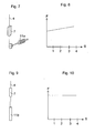
- Fig. 5 illustrates in a corresponding way as in fig. 3, a wave power assembly in accordance with the invention.
- the tension spring 11 is prestressed when the rotor is in the lower end position thereof. In that position, the spring 11 has a length of three times the length thereof at the neutral position. Thereby, already at the lower maximum end position thereof, the rotor is subjected to a force F 0 from the spring.
- an embodiment according to fig. 5 considerably reduces the problem of varying force, though to a limited extent. It is desirable to get the inclination of the graph as flat as possible. Even flatter inclination may naturally be obtained by utilizing an even longer spring that, in the lower end position of the rotor, is more extended than in the example shown in fig. 5. However, it may entail practical drawbacks to have a very long tension spring. The corresponding effect may in instead be obtained by letting the spring means be composed of a plurality of separate spring elements, which are connected in such a way that a flat characteristic is attained in the F-s graph.
- the spring means here consists of a gas spring 11 b.
- gas springs are available in designs with the spring force being substantially constant, independently of the extension.
- FIG. 11 An additional embodiment example is shown in fig. 11.
- a strut 14 is fastened on which a rubber body 15 each is fastened.
- the rubber bodies constitute a part of the total spring means that act on the rotor 7 and that in other respects may comprise someone of the previously described spring elements.
- the object of the rubber bodies is to get a smooth braking of the rotor next to the end position.
- a corresponding arrangement may be arranged at the lower maximum end position of the rotor. This embodiment is represented in the graph in fig. 13.
- the spring means 11 c may be composed of a plurality of springs, where each spring may have a particular characteristic and where the fastening point may be on different heights. Different types of springs may be comprised and be connected to each other in various ways.
- a spring force of a spring means may be controlled. This is symbolized in the figure by means of a displaceable fastening support 16, the position of which is affected by a control unit 17. This may be arranged to automatically control the position of the fastening support in response to signals on a sensor unit 18, which, e.g., may detect the current generated in the stator.
- the size of the spring force as a function of the position of the rotor need not necessarily be linear. In fig. 16, some examples are illustrated where this is not the case. Thus, the function may be such that the greater the distance of the rotor from the bottom position is, the more strongly the spring force increases, which corresponds to curve A. The opposite may also be feasible, as in curve B.
- the curves C and D represent courses of events with the spring force having a maximum and a minimum, respectively, at the centre position of the rotor.
- Curve E illustrates an additional alternative, where the function is composed of a plurality of linear sections. The illustrated functions may be obtained by suitable combination of springs and/or control of the force of the respective spring.
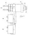
- a wave power plant according to the invention consists of two or more assemblies of the above-described kind. In fig. 17, it is illustrated how these are connected in order to deliver energy to a mains.
- the power plant consists of three assemblies symbolically indicated by 20a-20c. Each assembly is, via a breaker or contactor 21 and a rectifier 22, connected to an inverter 23, in a bipolar circuit according to the figure. In the figure, a circuit diagram is drawn only for the assembly 20a. It should be appreciated that the other assemblies 20b, 20c are correspondingly connected.
- the inverter 23 delivers three-phase current to the mains 25, possibly via a transformer 24 and/or a filter.
- the rectifiers may be diodes that may be gate-controlled and of the type IGBT, GTO or tyristor, comprise gate-controlled bipolar components or be uncontrolled.
- the voltages on the DC side may be connected in parallel, connected in series or a combination of both.
Landscapes
- Engineering & Computer Science (AREA)
- Chemical & Material Sciences (AREA)
- Combustion & Propulsion (AREA)
- Mechanical Engineering (AREA)
- General Engineering & Computer Science (AREA)
- Other Liquid Machine Or Engine Such As Wave Power Use (AREA)
- Control Of Motors That Do Not Use Commutators (AREA)
- Glass Compositions (AREA)
- Ceramic Products (AREA)
- Crystals, And After-Treatments Of Crystals (AREA)
- Superconductors And Manufacturing Methods Therefor (AREA)
- Non-Reversible Transmitting Devices (AREA)
- Amplifiers (AREA)
Abstract
Description
- The present invention relates in a first aspect to a wave power assembly, comprising a hull and a linear electric generator, the rotor of which by means of connection means is connected to the hull and the stator of which is arranged to be anchored at a sea/lake bottom, which assembly also comprises spring means arranged to exert a force on the rotor, which force during at least a part of the motion of the rotor is counter-directed the lifting force exerted by the hull on the rotor, the rotor as a consequence of motions of the hull and the force exerted by the spring means being arranged to execute a reciprocating motion between two end positions defining the length of stroke of the rotor, the assembly being arranged for a fixed maximum length of stroke. The direction of motion of the rotor defines the longitudinal direction of the generator and a plane perpendicular to the direction of motion defines the cross direction of the generator.
- In a second aspect, the invention relates to a wave power plant comprising a plurality of wave power assemblies according to the invention.
- In a third aspect, the invention relates to the use of the invented wave power assembly in order to produce electric current.
- In a fourth aspect, the invention relates to a method for the generation of electric energy.
- In the present application, the term rotor is used for the movable part of the linear generator. Thus, it should be appreciated that the term rotor does not relate to a rotary body but a linearly reciprocating body. Thus, by the direction of motion of the rotor, reference is made to the linear direction of motion thereof.
- The wave power assembly according to the invention is primarily intended for but not limited to applications up to 500 kW.
- The fact that the stator is arranged for anchorage at the bottom of the sea does not necessarily imply that it is situated on the same. Neither that it has to be stiffly connected to the bottom of the sea. Thus, the stator construction may naturally be floatingly supported and the anchorage may only consist of a line or the like, which prevents the assembly to drive away.
- Wave motions in the sea and large lakes are a potential energy source which till now is very little utilized. The available wave energy depends on the wave height and is naturally different for different locations. The average wave energy during a year is dependent on the different wind conditions, which are highly influenced by the distance of the location from the nearest coast. Measurements have, among other things, been made in the North Sea. At a measuring point approx. 100 km to the west of the coast of Jutland where the depth was approx. 50 m, measurings of the wave height have been made.
- In order to utilize the energy that is available by the motions of the sea waves, different types of wave power assemblies for the generation of electric power have been proposed. However, these have not succeeded to successfully compete with conventional electric power production. Wave power plants realized hitherto have in the main been test plants or used for local energy supply to navigation buoys. In order for commercial electricity production to be feasible, and thereby give access to the large energy reserve available in the motions of the sea waves, it is not only required that the setting out of the assemblies is carried out in suitably located places. It is also necessary that the assembly is reliable, has high efficiency as well as low manufacturing and operating costs.
- Among the feasible principles of the conversion of the wave motion energy to electric energy, a linear generator should in that connection to the largest extent meet these requirements.
- The vertical motions of the hull caused by the wave motions can thereby directly be transferred to a reciprocating motion of the rotor of the generator. A linear generator may be made very robust and simple and by it being anchored at the bottom, it becomes solidly unaffectable by streams in the water. The only movable part of the generator will be the reciprocating rotor. By the few movable parts thereof and the simple constructive build-up thereof, the assembly becomes very reliable.
- By, for instance, US 6 020 653, a wave power assembly is previously known, which is based on the linear generator principle. Hence, the specification describes a generator anchored at the bottom, which generator produces electric energy from the wave motions of the sea surface. A generator coil is connected to a hull so that the coil moves up and down with the wave motions. A magnetic field acts on the coil when it moves so that an electromagnetic force is generated in the same. The magnetic field is such that it provides a uniform field having a single magnetic orientation along the length of stroke of the entire coil. The generator comprises a base plate on the bottom of the sea that carries the magnetic core in which the coil moves.
- Furthermore, a wave power assembly provided with a linear electric generator is previously known by US 4 539 485. The rotor thereof consists of a number of permanent magnets and the winding of the generator is arranged in the surrounding stator.
- Further, in PCT/SE02/02405, a wave power assembly is disclosed having a linear generator in which the rotor is permanent magnetic and the stator comprises winding forming a plurality of poles distributed in the direction of motion of the rotor. A spring means is arranged in the form of a tension spring and exerts a downwardly directed tensile force on the rotor, i.e. directed against the lifting force of the hull.
- When the hull is lifted by a wave, this entails that the rotor in the generator is pulled upwards. One portion of the energy generated on that occasion is converted to electric energy and one portion is accumulated in the tension spring. When the hull then moves from a crest of a wave to a trough of a wave, the rotor is pulled downwards by the tension spring. Thereby, the energy accumulated in the spring is converted to electric energy.
- When a simple mechanical tension spring is used, the conversion to electric energy will be effected non-uniformly, which creates disturbances and causes inferior conditions for the energy conversion.
- The object of the present invention is, against this background, to seek to overcome said problem in a wave power assembly of the kind in question so that the conversion to electric energy is optimized.
- The object set-up has in a first aspect of the invention been attained by a wave power assembly of the kind defined in the preamble of
claim 1 comprising the special features of the spring means being arranged to, at a motion amplitude corresponding to 50 % of the maximum length of stroke of the rotor, exert a force, the size of which varies by a factor of 2,5 as a maximum. - The solution according to the invention is based on an identification of the causes for the emergence of the disturbances and the inferior energy conversion. The causes may be derived to the functional mode of a mechanical tension spring. The spring force of such a one is normally proportional to the extension of the spring from a neutral position. Thereby, the force exerted by the spring on the rotor will vary considerable during the motion of the rotor, and thereby also the speed of the rotor. Upon upward motion of the rotor, at the beginning a relatively large portion of the energy is transferred to electric energy and only a smaller portion to the spring, since on that occasion the counter force from the same is relatively small. During the later part of the motion, the relation becomes the opposite, since the spring force then is greater. A corresponding course of events also occurs upon the downward motion. Here, a decisive cause for the non-uniform energy conversion is to be found.
- Thus, based on this insight, according to the invention a spring means is used with said non-uniformity being reduced by the fact that variation of the spring force is limited. Thanks to the variation of the spring force having a maximum of 1:2,5 over said interval, the relation between the energy that is accumulated in the spring means and the energy that is converted to electric energy will vary relatively little during the motion of the rotor. The consequence becomes an improved conversion to electric energy.
- The limited variation of the spring force as a function of the position of the rotor can be provided in many different ways. For instance, a very long spring may be used, which already in the rotor position that corresponds to short spring length is so energised that the tensile force amounts to half the tensile force that appears in the other end position. Another way is that the spring means is composed of a plurality of springs, which give a total spring characteristic of the desired nature. The use of a torsion spring constitutes another feasible alternative. Furthermore, there are other types of springs than pure mechanical that advantageously may be used in order to achieve the desired force variation.
- According to a preferred embodiment of the invented wave power assembly, the size of the force of the spring means varies within said interval by a factor of 1,25 as a maximum. As should have been clear from the account above, it is desirable that the force varies as little as possible during the motion. Although already a variation range of 1:2,5 implies important advantages, it is even more favourable with a closer variation range. Therefore, a variation of 1:1,25 as a maximum implies an especially favourable embodiment.
- According to an additional preferred embodiment, the force is substantially constant. As should be clear from the reasoning immediately above, this constitutes the optimal embodiment with reference to the problem that the present invention is focused on.
- According to an additional preferred embodiment, the spring means is arranged to, at a motion amplitude corresponding to 90 % of the maximum length of stroke of the rotor, exert a force, the size of which varies by a factor of 10 as a maximum. It is true that the advantages of the invention are profited to a large extent also when the range of force-variation limitation only constitutes approx. 50 % of the maximum length of stroke, since the wave motions most often are within this range. Also when the wave motions are greater than so, the effect is still attained during the greater part of the motion. However, if the range of limitation of force variation is extended in accordance with this embodiment, the advantages of the invention will be possible to be fully profited also upon very strong wave motions.
- According to an additional preferred embodiment, the force varies by a factor of 1,5 as a maximum over said greater range. Thereby, an especially favourable embodiment is attained.
- According to an additional preferred embodiment, the spring means comprises a gas spring. Since such a one normally has a spring force that substantially is constant independent of the degree of extension, the use of a gas spring is in this connection extraordinarily expedient.
- According to an alternative embodiment, the spring means is mechanical. It is true that such a solution requires special measures in order to condition the spring characteristic. In certain applications, however, this embodiment may pres??ent an advantageously simple and reliable realization of the invention.
- According to an additional preferred embodiment, the spring means has a non-linear spring characteristic. This facilitates the optimization of the force variation while taking other conditions, which influence the course of events, into consideration.
- According to an additional preferred embodiment, the spring means comprises an actively controlled spring. Thereby, the alteration of the spring force can be adapted to specific circumstances that occur during the course of events, e.g. by controlling the spring force in dependence of some parameter significant for the efficiency of the energy conversion.
- According to an additional preferred embodiment, the spring means comprises a plurality of springs. This is a simple method to provide the desired profile for the variation of the force.
- According to an additional preferred embodiment, the spring means is arranged to, over a short distance next to the end position of the rotor that corresponds to the position of the hull on a crest of a wave, at the maximum length of stroke, exert a force that is many times greater than the maximum force below 90 % of the maximum length of stroke of the rotor. Thereby, a powerful braking is attained of the upward motion of the rotor in the final phase thereof when the wave motion is such that the maximum length of stroke is utilized. By means of this braking, risks of damage are avoided in comparison with a stiff stop limiting the length of stroke.
- In that connection, according to a preferred embodiment, said short distance constitutes less than 10 % of the maximum length of stroke of the rotor. A braking distance of that size is sufficiently large in order to enable a reasonably smooth braking and sufficiently small in order not to have any disturbing impact on the course of motion in other respects. Preferably, said distance is less than 5 % of the maximum length of stroke.
- According to an additional preferred embodiment, the force increases over said short distance with decreasing distance to the end position. The braking thereby becomes harmonious in that it to start with takes place smoothly and not until quite close to the end position with full strength.
- According to an additional preferred embodiment, the spring means comprises one or more separate spring elements for applying force over said short distance. In case the spring force over said distance should differ considerably from the one during the rest of the motion, one or more separate elements is a simple and expedient way to achieve this.
- In that connection, according to a preferred embodiment, each separate spring element is a mechanical compression or tension spring. Such a one is suitable for the achievement of the desirable characteristic during this phase. The element may preferably consist of a rubber body.
- The above-mentioned preferred embodiments of the invented wave power assembly are defined in the claims depending on
claim 1. - In the second, third and fourth aspects of the invention, the object set-up has been attained by a wave power plant comprising a plurality of wave power assemblies according to the invention, by the use of a wave power plant according to the invention in order to produce electric current, and by a method for production of electric current being carried out by means of a wave power assembly according to the invention, respectively, which are defined in
claims - By the invented wave power assembly, the invented use and the invented method, advantages of the corresponding type are gained as in the invented wave power assembly and the preferred embodiments of the same and that have been accounted for above.
- The invention is explained closer by the appended detailed description of advantageous embodiment examples of the same, reference being made to the appended drawing figures.
-
- Fig. 1
- is a schematic side view of a known wave power assembly of the type that the invention relates to.
- Fig. 2
- is a section along the line II-II in fig. 1.
- Fig. 3
- shows a detail of a wave power assembly that is outside the scope of the invention.
- Fig. 4
- is a graph illustrating the spring force as a function of motion distance in the wave power assembly according to fig. 3.
- Fig. 5
- shows in the same way as in fig. 3 a corresponding detail of a wave power assembly in accordance with the invention.
- Fig. 6
- is a graph corresponding to the one in fig. 4 and related to fig. 5.
- Fig. 7
- shows an alternative embodiment example of a detail of the invention.
- Fig. 8
- is a graph corresponding to the one in figs. 4 and 5 and that is related to the example in fig. 7.
- Fig. 9
- shows an additional alternative embodiment example of a detail of the invention.
- Fig. 10
- is a graph corresponding to the one in figs. 4 and 5 and that is related to the example in fig. 9.
- Fig. 11
- shows an additional alternative embodiment example of a detail of the invention.
- Fig. 12
- is a graph corresponding to the one in figs. 4 and 5 and that is related to the example in fig. 11.
- Fig. 13
- is a corresponding graph illustrating an additional embodiment example.
- Fig. 14
- illustrates an alternative embodiment example of the spring means.
- Fig. 15
- illustrates an additional alternative embodiment example of the spring means.
- Fig. 16
- is a graph illustrating alternative relationships between the position of the rotor and the spring force.
- Fig. 17
- is a diagram that illustrates the connection of a plurality of assemblies according to the invention into a wave power plant.
- Fig. 1 illustrates the principle of a wave power assembly according to the invention. A
hull 3 is arranged to float on thesea surface 2. Waves impart reciprocating vertical motion to thehull 3. At thebottom 1, alinear generator 5 is anchored via abase plate 8 fastened at the bottom, which plate may be a concrete slab. At thebase plate 8, thestator rotor 7 of the generator is arranged. The same is connected to thehull 3 by means of aline 4. Therotor 7 is of permanent magnetic material. - The
base plate 8 has a centrally arrangedhole 10, and concentrically therewith abottom hole 9 is recessed in the bottom of the sea. Thebottom hole 9 may suitably be lined. At the lower end of thebottom hole 9, atension spring 11 is fastened, which with the other ehd thereof is fastened at the lower end of therotor 7. Thehole 10 in thebase plate 8 and thebottom hole 9 have a diameter allowing therotor 7 to move freely through the same. - Each
stator pack stator pack 6a how the same is divided into three vertically distributedmodules - When the
hull 3 by the wave motions on thesea surface 2 moves up and down, this motion is transferred via theline 4 to therotor 7, which receives a corresponding reciprocating motion between the stator packs. Thereby, current is generated in the stator windings. Thebottom hole 9 allows the rotor to pass the entire stator in the downward motion thereof. Thetension spring 11 gives an additional force to the downward motion so that theline 4 at every instant is kept stretched. - The spring may also be formed so that it in certain situations also can exert an upwardly directed force. By means of a control means 28, the spring constant of the spring may be adjusted so that resonance is attained during as large a part of the time as possible.
- In order to be able to resist salt water, the stator is entirely or partly impregnated by VPI or silicone.
- Figure 2 is a section along the line II-II in fig. 1. In this example, the
rotor 7 has a square cross-section and astator pack 6a-6d is arranged at each side of therotor 7. The winding of the respective stator pack is indicated by 12a-12d. In the figure, the orientation of the sheet-metal plates in each stator pack is also seen. The air gap between the rotor and adjacent stator packs is in the order of some mm. - The basic principle of the present invention is illustrated in figs. 3-6. Fig. 3 illustrates schematically the
rotor 7 of a wave power assembly, atension spring 11 fastened at the same and theline 4 that connects therotor 7 with the hull. The figure is intended to illustrate the problem that the present invention is related to and shows therefore an embodiment being outside the scope of the invention. The rotor is shown in the lower maximum end position thereof. The figure is provided with a scale of lengths, where 0 represents the lower end position of the rotor and 4 the upper end position thereof. The unit of length may for the sake of simplicity be considered as metre. In the lower end position of the rotor, the spring is in the neutral position thereof and exerts no force on therotor 7. When therotor 7 by the lifting motion of the hull is pulled upwards, thespring 11 is energised so that the rotor at s = 1 is subjected to a tensile force F1 from the tension spring and at s = 2 by a tensile force F2 from the tension spring, etc. The force from the spring is proportional to the extension so that F2 = 2 F1, etc. - This is illustrated in the graph in fig. 4, with the spring force F being given as a function of the distance s of the rotor from the lower end position thereof. Accordingly, this increases powerfully during the upward motion, which results in the drawbacks mentioned in the introduction of the description. Also at a relatively moderate wave amplitude corresponding to a length of stroke of half the maximum, the force varies by a factor of 3. F0 = the force at the lower end position = 0. F4 = the force at the upper end position. For an amplitude of 90 % of the maximum length of stroke, the force will vary by a factor of 19.
- Fig. 5 illustrates in a corresponding way as in fig. 3, a wave power assembly in accordance with the invention. Here, the
tension spring 11 is prestressed when the rotor is in the lower end position thereof. In that position, thespring 11 has a length of three times the length thereof at the neutral position. Thereby, already at the lower maximum end position thereof, the rotor is subjected to a force F0 from the spring. When the rotor has moved 1 m upwards, with the indicated starting point, the spring force F1 becomes

- In the graph in fig. 6, in a corresponding way as in fig. 4, it is illustrated how the force varies with the distance of the rotor from the lower end position thereof. The force will vary by a factor of 3 between the end positions. Upon rotor motions of half the maximum length of stroke, at most the force will vary by a factor of 1,7. Upon rotor motions corresponding to 90 % of the maximum length of stroke, the force will vary by a factor of approx. 3.
- Hence, an embodiment according to fig. 5 considerably reduces the problem of varying force, though to a limited extent. It is desirable to get the inclination of the graph as flat as possible. Even flatter inclination may naturally be obtained by utilizing an even longer spring that, in the lower end position of the rotor, is more extended than in the example shown in fig. 5. However, it may entail practical drawbacks to have a very long tension spring. The corresponding effect may in instead be obtained by letting the spring means be composed of a plurality of separate spring elements, which are connected in such a way that a flat characteristic is attained in the F-s graph.
- In fig. 7, an alternative embodiment is shown, with the spring means consisting of a
torsion spring 11 a connected to the rotor via a motion transfer mechanism 13 that converts linear motion to rotary motion. - By a suitable design of the torsion spring and degree of prestress thereof, a relatively flat F-s graph can be obtained as is illustrated in fig. 8, with the spring force on the rotor between the maximum end positions thereof varying less than 20 %.
- In fig. 9, an additional alternative embodiment example of the invention is illustrated. The spring means here consists of a
gas spring 11 b. Such a one is exceptionally suitable in this connection, since gas springs are available in designs with the spring force being substantially constant, independently of the extension. - In fig. 10, this is illustrated in a graph of the corresponding type as in the previously shown graphs.
- An additional embodiment example is shown in fig. 11. At the upper end of the stator pack, on each stator unit a
strut 14 is fastened on which arubber body 15 each is fastened. When the rotor approaches the upper end position thereof, it will in the final stage abut against therubber bodies 15, which on that occasion being compressed. In that connection, the rubber bodies constitute a part of the total spring means that act on therotor 7 and that in other respects may comprise someone of the previously described spring elements. The object of the rubber bodies is to get a smooth braking of the rotor next to the end position. - From the moment when the rotor contacts the
rubber bodies 15, an intense downwardly directed force is added on the rotor, which develops very strongly when it compresses the rubber bodies. This course of events is illustrated graphically in fig. 12. - A corresponding arrangement may be arranged at the lower maximum end position of the rotor. This embodiment is represented in the graph in fig. 13.
- It should emphasized that the description made above is based on an idealized simplification. The picture is complicated by the upward and downward motion of the hull being non-uniform, depending on the shape of the waves. Furthermore, the immersion of the hull in the water will be influenced in dependence of the size of the counter force, which, together with the elasticity of the line, imparts additional contributions of elastic forces. However, these aspects have relatively marginal impact and do not take away the relevance of the fundamental principle
- In fig. 14, it is illustrated how the spring means 11 c may be composed of a plurality of springs, where each spring may have a particular characteristic and where the fastening point may be on different heights. Different types of springs may be comprised and be connected to each other in various ways.
- In fig. 15, it is illustrated how the spring force of a spring means may be controlled. This is symbolized in the figure by means of a
displaceable fastening support 16, the position of which is affected by acontrol unit 17. This may be arranged to automatically control the position of the fastening support in response to signals on asensor unit 18, which, e.g., may detect the current generated in the stator. - The size of the spring force as a function of the position of the rotor need not necessarily be linear. In fig. 16, some examples are illustrated where this is not the case. Thus, the function may be such that the greater the distance of the rotor from the bottom position is, the more strongly the spring force increases, which corresponds to curve A. The opposite may also be feasible, as in curve B. The curves C and D represent courses of events with the spring force having a maximum and a minimum, respectively, at the centre position of the rotor. Curve E illustrates an additional alternative, where the function is composed of a plurality of linear sections. The illustrated functions may be obtained by suitable combination of springs and/or control of the force of the respective spring.
- A wave power plant according to the invention consists of two or more assemblies of the above-described kind. In fig. 17, it is illustrated how these are connected in order to deliver energy to a mains. In the example shown, the power plant consists of three assemblies symbolically indicated by 20a-20c. Each assembly is, via a breaker or
contactor 21 and arectifier 22, connected to aninverter 23, in a bipolar circuit according to the figure. In the figure, a circuit diagram is drawn only for theassembly 20a. It should be appreciated that theother assemblies inverter 23 delivers three-phase current to themains 25, possibly via atransformer 24 and/or a filter. The rectifiers may be diodes that may be gate-controlled and of the type IGBT, GTO or tyristor, comprise gate-controlled bipolar components or be uncontrolled. - The voltages on the DC side may be connected in parallel, connected in series or a combination of both.
Claims (18)
- Wave power assembly comprising a hull (3) and a linear electric generator (5), the rotor (7) of which by means of connection means (4) is connected to the hull so that lifting force is transferred from the hull (3) to the rotor (7) and the stator (6) of which is arranged to be anchored at a sea/lake bottom (1), which assembly also comprises spring means (11, 11a, 11b) arranged to exert a force on the rotor (7), which force during at least a part of the motion of the rotor (7) is counter-directed the lifting force exerted on the rotor (7) by the hull (3), the rotor (7) as a consequence of the motion of the hull (3) and the force exerted by the spring means (11, 11a, 11b) being arranged to execute a reciprocating motion between two end positions defining the length of stroke of the rotor (7), the assembly being arranged for a fixed maximum length of stroke, characterized in that the spring means (11, 11a, 11b) is arranged to at a motion amplitude corresponding to 50 % of the maximum length of stroke of the rotor (7), exert a force, the size of which varies by a factor of 2,5 as a maximum.
- Wave power assembly according to claim 1, characterized in that the size of said force varies by a factor of 1,25 as a maximum.
- Wave power assembly according to claim 2, characterized in that the size of said force is substantially constant.
- Wave power assembly according to any one of claims 1-3, characterized in that the spring means (11, 11a, 11b) is arranged to, at a motion amplitude corresponding to 90 % of the maximum length of stroke of the rotor (7), exert a force, the size of which varies by a factor of 10 as a maximum.
- Wave power assembly according to claim 4, characterized in that the spring means (11, 11a, 11b) is arranged to, at a motion amplitude corresponding to 90 % of the maximum length of stroke of the rotor (7), exert a force, the size of which varies by a factor of 1,5 as a maximum.
- Wave power assembly according to any one of claims 1-5, characterized in that the spring means comprises a gas spring (11b).
- Wave power assembly according to any one of claims 1-6, characterized in that the spring means comprises a mechanical spring (11, 11a).
- Wave power assembly according to any one of claims 1-7, characterized in that the spring means has a non-linear spring characteristic.
- Wave power assembly according to any one of claims 1-8, characterized in that the spring means comprises an actively controlled spring.
- Wave power assembly according to any one of claims 1-9, characterized in that the spring means comprises a plurality of springs.
- Wave power assembly according to any one of claims 1-10, characterized in that the spring means is arranged to, over a short distance next to the end position of the rotor (7) that corresponds to the position of the hull (3) on a crest of a wave, at the maximum length of stroke, exert a force that is many times greater than the maximum force below a motion amplitude of 90 % of the maximum length of stroke of the rotor (7).
- Wave power assembly according to claim 11, characterized in that said short distance constitutes less than 10 % of the maximum length of stroke of the rotor.
- Wave power assembly according to claim 11-12, characterized in that the spring means (11, 11a, 11b, 15) is so arranged that the force next to said end position increases with decreasing distance to the end position.
- Wave power assembly according to any one of claims 11-13, characterized in that the spring means (11, 11a, 11b, 15) comprises one or more separate spring elements (15) for applying force over said short distance.
- Wave power assembly according to claim 14, characterized in that each of said separate spring elements (15) consists of a mechanical compression or tension spring.
- Wave power plant characterized in that it comprises a plurality of wave power assemblies (20a-20c) according to any one of claims 1-15.
- Use of a wave power assembly according to any one of claims 1-15 in order to generate electric energy.
- Method in order to generate electric energy characterized in that the electric energy is generated by means of one or more wave power assemblies according to any one of claims 1-15.
Priority Applications (1)
| Application Number | Priority Date | Filing Date | Title |
|---|---|---|---|
| PL04722496T PL1611348T3 (en) | 2003-03-27 | 2004-03-22 | Wave power assembly |
Applications Claiming Priority (2)
| Application Number | Priority Date | Filing Date | Title |
|---|---|---|---|
| SE0300870A SE0300870L (en) | 2003-03-27 | 2003-03-27 | Wave power units |
| PCT/SE2004/000421 WO2004085843A1 (en) | 2003-03-27 | 2004-03-22 | Wave power assembly |
Publications (2)
| Publication Number | Publication Date |
|---|---|
| EP1611348A1 EP1611348A1 (en) | 2006-01-04 |
| EP1611348B1 true EP1611348B1 (en) | 2006-10-11 |
Family
ID=20290821
Family Applications (1)
| Application Number | Title | Priority Date | Filing Date |
|---|---|---|---|
| EP04722496A Expired - Lifetime EP1611348B1 (en) | 2003-03-27 | 2004-03-22 | Wave power assembly |
Country Status (17)
| Country | Link |
|---|---|
| US (1) | US7304399B2 (en) |
| EP (1) | EP1611348B1 (en) |
| JP (1) | JP4398977B2 (en) |
| KR (1) | KR101080517B1 (en) |
| CN (1) | CN100545446C (en) |
| AT (1) | ATE342440T1 (en) |
| AU (1) | AU2004223484B2 (en) |
| CA (1) | CA2519780C (en) |
| CY (1) | CY1105888T1 (en) |
| DE (1) | DE602004002768T2 (en) |
| DK (1) | DK1611348T3 (en) |
| ES (1) | ES2274437T3 (en) |
| NO (1) | NO329569B1 (en) |
| PL (1) | PL1611348T3 (en) |
| PT (1) | PT1611348E (en) |
| SE (1) | SE0300870L (en) |
| WO (1) | WO2004085843A1 (en) |
Families Citing this family (31)
| Publication number | Priority date | Publication date | Assignee | Title |
|---|---|---|---|---|
| SE523000C2 (en) * | 2003-03-27 | 2004-03-23 | Swedish Seabased Energy Ab | Wave power unit |
| AU2005206866B2 (en) * | 2004-01-14 | 2011-02-03 | Ocean Power Technologies, Inc. | Active impedance matching systems and methods for wave energy converter |
| US7323790B2 (en) * | 2005-03-15 | 2008-01-29 | Ocean Power Technologies, Inc. | Wave energy converters (WECs) with linear electric generators (LEGs) |
| NO324807B1 (en) * | 2005-03-22 | 2007-12-10 | Jon Eirik Brennvall | Frequency converter for wave power plants and similar applications |
| GB2434409A (en) * | 2006-01-24 | 2007-07-25 | William Kingston | Tidal energy system |
| US7420287B2 (en) * | 2006-03-28 | 2008-09-02 | Aleksandr Smushkovich | Intermittent force powered electromagnetic converters especially for sea waves |
| WO2007111546A1 (en) * | 2006-03-29 | 2007-10-04 | Seabased Ab | A system for generating electric energy |
| US7538445B2 (en) * | 2006-05-05 | 2009-05-26 | Sri International | Wave powered generation |
| US7557456B2 (en) * | 2006-05-05 | 2009-07-07 | Sri International | Wave powered generation using electroactive polymers |
| US7304398B1 (en) * | 2006-05-30 | 2007-12-04 | Hyun Bong Kim | Spring activated energy transducer generating A/C electricity from natural forces-frictionless magnetic plate |
| EP1983190A1 (en) | 2007-04-18 | 2008-10-22 | Technology for Ideas | Damper and damping structure for a wave energy conversion device |
| US7554215B1 (en) * | 2007-07-03 | 2009-06-30 | Paul Caragine | Generator and method for generating electricity from subsurface currents |
| DK176883B1 (en) * | 2008-09-19 | 2010-02-22 | Wavepiston Aps | Wave energy extraction apparatus |
| EP2350450A2 (en) * | 2008-10-29 | 2011-08-03 | Inventua APS | Rotating apparatus |
| US7816797B2 (en) * | 2009-01-07 | 2010-10-19 | Oscilla Power Inc. | Method and device for harvesting energy from ocean waves |
| NO330266B1 (en) * | 2009-05-27 | 2011-03-14 | Nbt As | Device using pressure transients for transport of fluids |
| DE102009030175A1 (en) | 2009-06-24 | 2010-12-30 | Robert Bosch Gmbh | Energy generation arrangement for use in seabed, has area and coil, which are arranged such that two ends of area are respectively arranged within and outside of active length of coil during reversal of linear movement |
| DE102010024334A1 (en) | 2009-11-18 | 2011-05-19 | Robert Bosch Gmbh | Wave energy plant has stator that is arranged in body of flotation body and reaction body such that rotor slides along stator |
| ES2855145T3 (en) * | 2010-05-28 | 2021-09-23 | Seabased Ab | Stator Frame for Submerged Linear Generator |
| EP2577046B1 (en) * | 2010-05-28 | 2018-07-04 | Seabased AB | A wave power unit, a use of a such and a method of producing electric energy |
| CN102971483B (en) | 2010-06-17 | 2016-02-03 | 压力技术系统公司 | The method of pressure transient is adopted in hydrocarbon recovery operations |
| US20120086205A1 (en) * | 2010-10-08 | 2012-04-12 | Balakrishnan Nair | Method and device for harvesting energy from ocean waves |
| CN103562060B (en) | 2011-03-22 | 2017-10-27 | 技术源于思维有限公司 | With the mooring component to the smooth stress strain response of top load |
| AR089304A1 (en) | 2011-12-19 | 2014-08-13 | Impact Technology Systems As | IMPACT PRESSURE RECOVERY METHOD |
| US8723353B1 (en) * | 2012-11-21 | 2014-05-13 | Barrie Franklin | Wave energy converter design incorporating an induction generator |
| DE102014004661A1 (en) | 2014-03-31 | 2015-10-01 | loannis Mariggis | Floating device and floating system comprising a plurality of devices for generating electrical energy by water waves |
| DE202014003764U1 (en) | 2014-03-31 | 2014-06-24 | loannis Mariggis | Floating device and floating system comprising a plurality of devices for generating electrical energy by water waves |
| JP5926428B2 (en) * | 2014-08-12 | 2016-05-25 | 西浦 信一 | Power generation system and reciprocating mechanism for power generation system |
| WO2016024520A1 (en) * | 2014-08-12 | 2016-02-18 | 西風技研株式会社 | Power generation system and reciprocating motion mechanism for power generation system |
| EP3923438A1 (en) | 2020-06-08 | 2021-12-15 | Seabased AB | Method for determining the arrangement of wave energy converters |
| US12068664B1 (en) * | 2024-02-26 | 2024-08-20 | Cyclazoom, LLC | Energy generating system |
Family Cites Families (14)
| Publication number | Priority date | Publication date | Assignee | Title |
|---|---|---|---|---|
| GB1316950A (en) * | 1969-06-30 | 1973-05-16 | Univ North Wales | Electric generator |
| US4355511A (en) * | 1977-07-22 | 1982-10-26 | Dedger Jones | Wave energy conversion |
| US4291234A (en) * | 1979-12-17 | 1981-09-22 | Clark Steven J | Apparatus for generating electricity |
| US4434375A (en) * | 1982-06-30 | 1984-02-28 | Taylor Robert N | Wave energy converter |
| US4754157A (en) * | 1985-10-01 | 1988-06-28 | Windle Tom J | Float type wave energy extraction apparatus and method |
| JP2522175Y2 (en) * | 1990-09-25 | 1997-01-08 | 黒石鉄工株式会社 | Wave oscillation type power generation light emission float |
| GB2272026A (en) * | 1992-10-29 | 1994-05-04 | William Chilton | Electrical power generation from waves |
| CN1075600C (en) * | 1994-03-07 | 2001-11-28 | 孙立言 | Wave energy unit |
| US6229225B1 (en) * | 1997-05-08 | 2001-05-08 | Ocean Power Technologies, Inc. | Surface wave energy capture system |
| US6020653A (en) * | 1997-11-18 | 2000-02-01 | Aqua Magnetics, Inc. | Submerged reciprocating electric generator |
| DE69817608D1 (en) * | 1997-12-03 | 2003-10-02 | William Dick | SEA wave transducer |
| US6695536B2 (en) * | 2001-03-16 | 2004-02-24 | Gines Sanchez Gomez | Floating platform to obtain electric power from sea waves |
| SE520921C2 (en) * | 2002-01-10 | 2003-09-16 | Swedish Seabased Energy Ab | Wave power unit for generation of electricity has a float that moves with the waves and is mechanically coupled to a linear generator |
| JP4732690B2 (en) * | 2002-01-10 | 2011-07-27 | スウェディッシュ シーベイスト エナジー アクチボラグ | Wave power device, use of wave power device for power generation, power generation method, and set of components for manufacturing linear generator for wave power device |
-
2003
- 2003-03-27 SE SE0300870A patent/SE0300870L/en not_active IP Right Cessation
-
2004
- 2004-03-22 WO PCT/SE2004/000421 patent/WO2004085843A1/en not_active Ceased
- 2004-03-22 DE DE602004002768T patent/DE602004002768T2/en not_active Expired - Lifetime
- 2004-03-22 DK DK04722496T patent/DK1611348T3/en active
- 2004-03-22 EP EP04722496A patent/EP1611348B1/en not_active Expired - Lifetime
- 2004-03-22 CA CA2519780A patent/CA2519780C/en not_active Expired - Fee Related
- 2004-03-22 ES ES04722496T patent/ES2274437T3/en not_active Expired - Lifetime
- 2004-03-22 AU AU2004223484A patent/AU2004223484B2/en not_active Ceased
- 2004-03-22 JP JP2006507975A patent/JP4398977B2/en not_active Expired - Fee Related
- 2004-03-22 KR KR1020057018202A patent/KR101080517B1/en not_active Expired - Fee Related
- 2004-03-22 PT PT04722496T patent/PT1611348E/en unknown
- 2004-03-22 CN CNB2004800083102A patent/CN100545446C/en not_active Expired - Fee Related
- 2004-03-22 US US10/550,901 patent/US7304399B2/en not_active Expired - Fee Related
- 2004-03-22 AT AT04722496T patent/ATE342440T1/en not_active IP Right Cessation
- 2004-03-22 PL PL04722496T patent/PL1611348T3/en unknown
- 2004-03-26 NO NO20041283A patent/NO329569B1/en not_active IP Right Cessation
-
2006
- 2006-12-29 CY CY20061101862T patent/CY1105888T1/en unknown
Also Published As
| Publication number | Publication date |
|---|---|
| PT1611348E (en) | 2007-01-31 |
| SE0300870D0 (en) | 2003-03-27 |
| SE522999C2 (en) | 2004-03-23 |
| CY1105888T1 (en) | 2011-02-02 |
| KR101080517B1 (en) | 2011-11-04 |
| DE602004002768D1 (en) | 2006-11-23 |
| WO2004085843A8 (en) | 2005-01-06 |
| US7304399B2 (en) | 2007-12-04 |
| CA2519780A1 (en) | 2004-10-07 |
| WO2004085843A1 (en) | 2004-10-07 |
| NO20041283L (en) | 2004-09-28 |
| PL1611348T3 (en) | 2007-03-30 |
| HK1088057A1 (en) | 2006-10-27 |
| ES2274437T3 (en) | 2007-05-16 |
| KR20060008304A (en) | 2006-01-26 |
| JP4398977B2 (en) | 2010-01-13 |
| US20070090652A1 (en) | 2007-04-26 |
| SE0300870L (en) | 2004-03-23 |
| JP2006521502A (en) | 2006-09-21 |
| CN1764780A (en) | 2006-04-26 |
| ATE342440T1 (en) | 2006-11-15 |
| CA2519780C (en) | 2012-05-08 |
| DE602004002768T2 (en) | 2007-08-16 |
| EP1611348A1 (en) | 2006-01-04 |
| AU2004223484A1 (en) | 2004-10-07 |
| DK1611348T3 (en) | 2007-02-19 |
| NO329569B1 (en) | 2010-11-15 |
| AU2004223484B2 (en) | 2009-09-17 |
| CN100545446C (en) | 2009-09-30 |
Similar Documents
| Publication | Publication Date | Title |
|---|---|---|
| US7304399B2 (en) | Wave power assembly | |
| EP1649162B1 (en) | Wave power assembly provided with an electromagnetic dampning means | |
| US6864592B1 (en) | Sea wave to electrical energy conversion plant | |
| EP1474607B1 (en) | A wave-power unit and the use of a wave-power unit for production of electric power, a method of generating electric power and a system of components for manufacturing a linear generator for a wave-power unit | |
| US7164212B2 (en) | Electric device and method | |
| US3783302A (en) | Apparatus and method for converting wave energy into electrical energy | |
| AU2009321364A1 (en) | Low cost linear generator wave energy converters | |
| US20110121573A1 (en) | Device for harnessing ocean wave energy for generation of electricity | |
| CN114731092A (en) | Electric power generator | |
| HK1088057B (en) | Wave power assembly | |
| CN112003447A (en) | Four-connecting-rod sea wave pressure power generation blanket | |
| CA1055568A (en) | Apparatus and method for converting wave energy into electrical energy |
Legal Events
| Date | Code | Title | Description |
|---|---|---|---|
| PUAI | Public reference made under article 153(3) epc to a published international application that has entered the european phase |
Free format text: ORIGINAL CODE: 0009012 |
|
| 17P | Request for examination filed |
Effective date: 20051027 |
|
| AK | Designated contracting states |
Kind code of ref document: A1 Designated state(s): AT BE BG CH CY CZ DE DK EE ES FI FR GB GR HU IE IT LI LU MC NL PL PT RO SE SI SK TR |
|
| AX | Request for extension of the european patent |
Extension state: AL LT LV MK |
|
| GRAP | Despatch of communication of intention to grant a patent |
Free format text: ORIGINAL CODE: EPIDOSNIGR1 |
|
| DAX | Request for extension of the european patent (deleted) | ||
| GRAS | Grant fee paid |
Free format text: ORIGINAL CODE: EPIDOSNIGR3 |
|
| GRAA | (expected) grant |
Free format text: ORIGINAL CODE: 0009210 |
|
| AK | Designated contracting states |
Kind code of ref document: B1 Designated state(s): AT BE BG CH CY CZ DE DK EE ES FI FR GB GR HU IE IT LI LU MC NL PL PT RO SE SI SK TR |
|
| PG25 | Lapsed in a contracting state [announced via postgrant information from national office to epo] |
Ref country code: SI Free format text: LAPSE BECAUSE OF FAILURE TO SUBMIT A TRANSLATION OF THE DESCRIPTION OR TO PAY THE FEE WITHIN THE PRESCRIBED TIME-LIMIT Effective date: 20061011 Ref country code: SK Free format text: LAPSE BECAUSE OF FAILURE TO SUBMIT A TRANSLATION OF THE DESCRIPTION OR TO PAY THE FEE WITHIN THE PRESCRIBED TIME-LIMIT Effective date: 20061011 Ref country code: AT Free format text: LAPSE BECAUSE OF FAILURE TO SUBMIT A TRANSLATION OF THE DESCRIPTION OR TO PAY THE FEE WITHIN THE PRESCRIBED TIME-LIMIT Effective date: 20061011 Ref country code: CZ Free format text: LAPSE BECAUSE OF FAILURE TO SUBMIT A TRANSLATION OF THE DESCRIPTION OR TO PAY THE FEE WITHIN THE PRESCRIBED TIME-LIMIT Effective date: 20061011 Ref country code: CH Free format text: LAPSE BECAUSE OF FAILURE TO SUBMIT A TRANSLATION OF THE DESCRIPTION OR TO PAY THE FEE WITHIN THE PRESCRIBED TIME-LIMIT Effective date: 20061011 Ref country code: LI Free format text: LAPSE BECAUSE OF FAILURE TO SUBMIT A TRANSLATION OF THE DESCRIPTION OR TO PAY THE FEE WITHIN THE PRESCRIBED TIME-LIMIT Effective date: 20061011 |
|
| REG | Reference to a national code |
Ref country code: GB Ref legal event code: FG4D |
|
| REG | Reference to a national code |
Ref country code: CH Ref legal event code: EP |
|
| REG | Reference to a national code |
Ref country code: IE Ref legal event code: FG4D |
|
| REF | Corresponds to: |
Ref document number: 602004002768 Country of ref document: DE Date of ref document: 20061123 Kind code of ref document: P |
|
| PG25 | Lapsed in a contracting state [announced via postgrant information from national office to epo] |
Ref country code: BG Free format text: LAPSE BECAUSE OF FAILURE TO SUBMIT A TRANSLATION OF THE DESCRIPTION OR TO PAY THE FEE WITHIN THE PRESCRIBED TIME-LIMIT Effective date: 20070111 Ref country code: SE Free format text: LAPSE BECAUSE OF FAILURE TO SUBMIT A TRANSLATION OF THE DESCRIPTION OR TO PAY THE FEE WITHIN THE PRESCRIBED TIME-LIMIT Effective date: 20070111 |
|
| REG | Reference to a national code |
Ref country code: RO Ref legal event code: EPE |
|
| REG | Reference to a national code |
Ref country code: PT Ref legal event code: SC4A Free format text: AVAILABILITY OF NATIONAL TRANSLATION Effective date: 20061221 |
|
| REG | Reference to a national code |
Ref country code: EE Ref legal event code: FG4A Ref document number: E000831 Country of ref document: EE Effective date: 20061219 Ref country code: GR Ref legal event code: EP Ref document number: 20070400043 Country of ref document: GR |
|
| REG | Reference to a national code |
Ref country code: PL Ref legal event code: T3 |
|
| ET | Fr: translation filed | ||
| REG | Reference to a national code |
Ref country code: CH Ref legal event code: PL |
|
| REG | Reference to a national code |
Ref country code: ES Ref legal event code: FG2A Ref document number: 2274437 Country of ref document: ES Kind code of ref document: T3 |
|
| PLBE | No opposition filed within time limit |
Free format text: ORIGINAL CODE: 0009261 |
|
| STAA | Information on the status of an ep patent application or granted ep patent |
Free format text: STATUS: NO OPPOSITION FILED WITHIN TIME LIMIT |
|
| 26N | No opposition filed |
Effective date: 20070712 |
|
| PG25 | Lapsed in a contracting state [announced via postgrant information from national office to epo] |
Ref country code: MC Free format text: LAPSE BECAUSE OF NON-PAYMENT OF DUE FEES Effective date: 20070331 |
|
| PG25 | Lapsed in a contracting state [announced via postgrant information from national office to epo] |
Ref country code: LU Free format text: LAPSE BECAUSE OF NON-PAYMENT OF DUE FEES Effective date: 20070322 |
|
| PG25 | Lapsed in a contracting state [announced via postgrant information from national office to epo] |
Ref country code: HU Free format text: LAPSE BECAUSE OF FAILURE TO SUBMIT A TRANSLATION OF THE DESCRIPTION OR TO PAY THE FEE WITHIN THE PRESCRIBED TIME-LIMIT Effective date: 20070412 |
|
| PGFP | Annual fee paid to national office [announced via postgrant information from national office to epo] |
Ref country code: EE Payment date: 20100324 Year of fee payment: 7 Ref country code: RO Payment date: 20100318 Year of fee payment: 7 |
|
| PGFP | Annual fee paid to national office [announced via postgrant information from national office to epo] |
Ref country code: PL Payment date: 20100309 Year of fee payment: 7 |
|
| PGFP | Annual fee paid to national office [announced via postgrant information from national office to epo] |
Ref country code: TR Payment date: 20100317 Year of fee payment: 7 |
|
| PGFP | Annual fee paid to national office [announced via postgrant information from national office to epo] |
Ref country code: GR Payment date: 20110329 Year of fee payment: 8 |
|
| PGFP | Annual fee paid to national office [announced via postgrant information from national office to epo] |
Ref country code: CY Payment date: 20110308 Year of fee payment: 8 |
|
| REG | Reference to a national code |
Ref country code: EE Ref legal event code: MM4A Ref document number: E000831 Country of ref document: EE Effective date: 20110331 |
|
| PG25 | Lapsed in a contracting state [announced via postgrant information from national office to epo] |
Ref country code: EE Free format text: LAPSE BECAUSE OF NON-PAYMENT OF DUE FEES Effective date: 20110331 |
|
| PG25 | Lapsed in a contracting state [announced via postgrant information from national office to epo] |
Ref country code: RO Free format text: LAPSE BECAUSE OF NON-PAYMENT OF DUE FEES Effective date: 20110322 |
|
| REG | Reference to a national code |
Ref country code: PL Ref legal event code: LAPE |
|
| PG25 | Lapsed in a contracting state [announced via postgrant information from national office to epo] |
Ref country code: PL Free format text: LAPSE BECAUSE OF NON-PAYMENT OF DUE FEES Effective date: 20110322 |
|
| PG25 | Lapsed in a contracting state [announced via postgrant information from national office to epo] |
Ref country code: CY Free format text: LAPSE BECAUSE OF NON-PAYMENT OF DUE FEES Effective date: 20120322 |
|
| REG | Reference to a national code |
Ref country code: GR Ref legal event code: ML Ref document number: 20070400043 Country of ref document: GR Effective date: 20121008 |
|
| PG25 | Lapsed in a contracting state [announced via postgrant information from national office to epo] |
Ref country code: GR Free format text: LAPSE BECAUSE OF NON-PAYMENT OF DUE FEES Effective date: 20121008 |
|
| PG25 | Lapsed in a contracting state [announced via postgrant information from national office to epo] |
Ref country code: TR Free format text: LAPSE BECAUSE OF NON-PAYMENT OF DUE FEES Effective date: 20110322 |
|
| PGFP | Annual fee paid to national office [announced via postgrant information from national office to epo] |
Ref country code: NL Payment date: 20140314 Year of fee payment: 11 Ref country code: FI Payment date: 20140319 Year of fee payment: 11 |
|
| PGFP | Annual fee paid to national office [announced via postgrant information from national office to epo] |
Ref country code: IT Payment date: 20140312 Year of fee payment: 11 |
|
| PGFP | Annual fee paid to national office [announced via postgrant information from national office to epo] |
Ref country code: BE Payment date: 20140321 Year of fee payment: 11 |
|
| REG | Reference to a national code |
Ref country code: FR Ref legal event code: PLFP Year of fee payment: 12 |
|
| PGFP | Annual fee paid to national office [announced via postgrant information from national office to epo] |
Ref country code: DE Payment date: 20150325 Year of fee payment: 12 Ref country code: IE Payment date: 20150317 Year of fee payment: 12 Ref country code: ES Payment date: 20150325 Year of fee payment: 12 Ref country code: DK Payment date: 20150324 Year of fee payment: 12 |
|
| PGFP | Annual fee paid to national office [announced via postgrant information from national office to epo] |
Ref country code: GB Payment date: 20150325 Year of fee payment: 12 |
|
| PGFP | Annual fee paid to national office [announced via postgrant information from national office to epo] |
Ref country code: FR Payment date: 20150331 Year of fee payment: 12 |
|
| PG25 | Lapsed in a contracting state [announced via postgrant information from national office to epo] |
Ref country code: FI Free format text: LAPSE BECAUSE OF NON-PAYMENT OF DUE FEES Effective date: 20150322 |
|
| REG | Reference to a national code |
Ref country code: NL Ref legal event code: MM Effective date: 20150401 |
|
| PG25 | Lapsed in a contracting state [announced via postgrant information from national office to epo] |
Ref country code: IT Free format text: LAPSE BECAUSE OF NON-PAYMENT OF DUE FEES Effective date: 20150322 |
|
| REG | Reference to a national code |
Ref country code: DE Ref legal event code: R119 Ref document number: 602004002768 Country of ref document: DE |
|
| REG | Reference to a national code |
Ref country code: DK Ref legal event code: EBP Effective date: 20160331 |
|
| GBPC | Gb: european patent ceased through non-payment of renewal fee |
Effective date: 20160322 |
|
| PG25 | Lapsed in a contracting state [announced via postgrant information from national office to epo] |
Ref country code: PT Free format text: LAPSE BECAUSE OF NON-PAYMENT OF DUE FEES Effective date: 20160922 |
|
| REG | Reference to a national code |
Ref country code: IE Ref legal event code: MM4A |
|
| REG | Reference to a national code |
Ref country code: FR Ref legal event code: ST Effective date: 20161130 |
|
| PG25 | Lapsed in a contracting state [announced via postgrant information from national office to epo] |
Ref country code: IE Free format text: LAPSE BECAUSE OF NON-PAYMENT OF DUE FEES Effective date: 20160322 Ref country code: DE Free format text: LAPSE BECAUSE OF NON-PAYMENT OF DUE FEES Effective date: 20161001 Ref country code: GB Free format text: LAPSE BECAUSE OF NON-PAYMENT OF DUE FEES Effective date: 20160322 Ref country code: FR Free format text: LAPSE BECAUSE OF NON-PAYMENT OF DUE FEES Effective date: 20160331 |
|
| PG25 | Lapsed in a contracting state [announced via postgrant information from national office to epo] |
Ref country code: PT Free format text: LAPSE BECAUSE OF NON-PAYMENT OF DUE FEES Effective date: 20160922 |
|
| PGRI | Patent reinstated in contracting state [announced from national office to epo] |
Ref country code: PT Effective date: 20161011 |
|
| REG | Reference to a national code |
Ref country code: ES Ref legal event code: FD2A Effective date: 20170426 |
|
| PG25 | Lapsed in a contracting state [announced via postgrant information from national office to epo] |
Ref country code: DK Free format text: LAPSE BECAUSE OF NON-PAYMENT OF DUE FEES Effective date: 20160331 |
|
| PG25 | Lapsed in a contracting state [announced via postgrant information from national office to epo] |
Ref country code: NL Free format text: LAPSE BECAUSE OF NON-PAYMENT OF DUE FEES Effective date: 20150401 |
|
| PG25 | Lapsed in a contracting state [announced via postgrant information from national office to epo] |
Ref country code: BE Free format text: LAPSE BECAUSE OF NON-PAYMENT OF DUE FEES Effective date: 20150331 |
|
| PG25 | Lapsed in a contracting state [announced via postgrant information from national office to epo] |
Ref country code: ES Free format text: LAPSE BECAUSE OF NON-PAYMENT OF DUE FEES Effective date: 20160323 |
|
| PGFP | Annual fee paid to national office [announced via postgrant information from national office to epo] |
Ref country code: PT Payment date: 20190726 Year of fee payment: 16 |
|
| PG25 | Lapsed in a contracting state [announced via postgrant information from national office to epo] |
Ref country code: PT Free format text: LAPSE BECAUSE OF NON-PAYMENT OF DUE FEES Effective date: 20200922 |