EP1611035B1 - Hopper structure, method of controlling the emptying of such a hopper structure, and a waste chute having such a hopper structure - Google Patents
Hopper structure, method of controlling the emptying of such a hopper structure, and a waste chute having such a hopper structure Download PDFInfo
- Publication number
- EP1611035B1 EP1611035B1 EP03713159A EP03713159A EP1611035B1 EP 1611035 B1 EP1611035 B1 EP 1611035B1 EP 03713159 A EP03713159 A EP 03713159A EP 03713159 A EP03713159 A EP 03713159A EP 1611035 B1 EP1611035 B1 EP 1611035B1
- Authority
- EP
- European Patent Office
- Prior art keywords
- hopper
- movement
- loading
- support structure
- rear wall
- Prior art date
- Legal status (The legal status is an assumption and is not a legal conclusion. Google has not performed a legal analysis and makes no representation as to the accuracy of the status listed.)
- Expired - Lifetime
Links
- 239000002699 waste material Substances 0.000 title claims description 28
- 238000000034 method Methods 0.000 title claims description 5
- 230000005540 biological transmission Effects 0.000 claims abstract description 12
- 239000000463 material Substances 0.000 claims description 17
- 238000013016 damping Methods 0.000 claims description 8
- 230000000750 progressive effect Effects 0.000 claims description 3
- 230000007704 transition Effects 0.000 description 5
- 238000003780 insertion Methods 0.000 description 4
- 230000037431 insertion Effects 0.000 description 4
- 230000008901 benefit Effects 0.000 description 3
- 230000006378 damage Effects 0.000 description 3
- 230000003213 activating effect Effects 0.000 description 2
- 235000002918 Fraxinus excelsior Nutrition 0.000 description 1
- 230000009471 action Effects 0.000 description 1
- 239000002956 ash Substances 0.000 description 1
- 239000013256 coordination polymer Substances 0.000 description 1
- 230000000977 initiatory effect Effects 0.000 description 1
- 230000003993 interaction Effects 0.000 description 1
- 238000012986 modification Methods 0.000 description 1
- 230000004048 modification Effects 0.000 description 1
- 238000005192 partition Methods 0.000 description 1
- 230000000087 stabilizing effect Effects 0.000 description 1
Images




Classifications
-
- E—FIXED CONSTRUCTIONS
- E04—BUILDING
- E04F—FINISHING WORK ON BUILDINGS, e.g. STAIRS, FLOORS
- E04F17/00—Vertical ducts; Channels, e.g. for drainage
- E04F17/10—Arrangements in buildings for the disposal of refuse
- E04F17/12—Chutes
-
- B—PERFORMING OPERATIONS; TRANSPORTING
- B65—CONVEYING; PACKING; STORING; HANDLING THIN OR FILAMENTARY MATERIAL
- B65F—GATHERING OR REMOVAL OF DOMESTIC OR LIKE REFUSE
- B65F1/00—Refuse receptacles; Accessories therefor
- B65F1/10—Refuse receptacles; Accessories therefor with refuse filling means, e.g. air-locks
Definitions
- the present invention generally relates to the feeding of material into a receiving body. More specifically, the invention relates to a hopper structure for feeding fixed maximum volumes of a material, said hopper being pivoted between an outwardly open loading position and an outwardly closed discharge position.
- pivotal hopper units have been generally employed for receiving volumes of material, such as ashes and waste, for subsequent discharge into a receiving body in the form of a waste container, a refuse chute etc.
- the traditional feed hopper unit is pivotally supported in a frame, has parallel side walls and converging front and rear walls extended between and connected to the side walls. The front and rear walls converge downwardly to form a tapered receptacle into which a fixed maximum volume of material can be loaded.
- a main drawback of this general design is that it requires a compromise between several desirable aspects, namely the desire to provide an infeed apparatus that: allows only the infeed of a maximum volume of material; permits only the introduction of items smaller than specified dimensions; presents a generous infeed opening; has an acceptably short path of movement between the infeed an discharge positions, and; provides for secure discharge of the complete hopper load.
- the invention eliminates the above discussed problems and shortcomings of the prior art.
- a basic object of the invention is to provide comfortable operation and compact design of an infeed apparatus while simultaneously controlling the volume and dimensions of material and items, respectively, that may be introduced into a receiving body through said apparatus.
- a specific object of the invention is to provide an improved hopper unit permitting comfortable loading and discharge of material and at the same time permitting only the introduction of a fixed maximum volume of material and/or of items being smaller than specified, predetermined dimensions.
- Another object of the invention is to provide such a hopper unit that occupies only a restricted amount of space in a receiving body.
- the invention concerns a hopper unit having a hopper structure comprising one wall being moveable between closed and open conditions. Movement of said wall is functionally connected, through a transmission, to the movement of the hopper structure between loading and discharge positions.
- a hopper unit having a hopper structure comprising one wall being moveable between closed and open conditions. Movement of said wall is functionally connected, through a transmission, to the movement of the hopper structure between loading and discharge positions.
- the movement of the hopper structure is transmitted to the moveable wall through a cam follower that is attached to said wall and that is received in a fixed cam groove.
- a further object of the invention is to provide an improved method of controlling the discharge from a hopper unit having a fixed volume hopper structure, so that a very comfortable and compact hopper operation is achieved, in the sense that a comparatively short path of movement and a small space is required for said operation.
- this object is achieved by pivoting a wall of the hopper structure between closed and open conditions and by controlling the movement of said wall in dependence upon the pivoting of the hopper structure.
- it is possible to control the hopper structure so that it remains in its fixed volume condition during at least a major portion of its movement from its open loading position to a closed position where no further loading is possible.
- a slight further pivoting thereof activates and/or controls the opening of the moveable wall and thereby a secure discharge of the loaded material.
- Yet another object of the invention is to provide an improved waste chute of a waste collection system, where a waste inlet structure allows only the insertion of predetermined maximum volumes of waste into the chute in each operation, inhibits the insertion of items exceeding predetermined dimensions and requires minimum space within the chute during its entire operation.
- this object is achieved by positioning a hopper unit as suggested by the invention in an inlet opening or each inlet opening of the chute.
- Figs. 1 and 2 illustrate a hopper unit 2 according to the invention in an application where it is installed in a very schematically depicted receiving body in the shape of a waste chute 1.
- the waste chute 1 is part of a waste collection system that is not illustrated or described in any further detail.
- the waste chute 1 has a waste inlet opening 1A into which the hopper unit 2 is fitted, and said chute may for instance be an isolated ground floor waste chute of a vacuum collection system. Although only the single inlet opening 1A is shown in the drawings, it should be noted that the chute 1 may also be a section of a waste chute of a multi-story building, containing several inlets provided at different levels.
- the hopper unit 2 consists of a support structure 4 that in this embodiment is a separate frame 4 that is inserted into the inlet opening 1A and that is attached to the chute 1.
- the frame 4 has a front plate 4A that is preferably bolted to the exterior of a chute wall, surrounding the opening 1A.
- a hopper guide structure is provided, consisting of two spaced parallel guide walls 4B that extend into the chute 1.
- a cover plate 4C upwardly closes off the space between said guide walls 4B, and serves mainly to stabilize the guide structure. To a certain extent said cover plate in certain applications also protects the hopper unit from items or material falling from a higher level of the chute, such as in the above mentioned waste chute of a multi-story building.
- a hopper structure 3 is pivotally supported in the support structure 4, for pivoting around a first horizontal axis H1.
- the hopper structure is pivotally supported on a pivot pin 12 that is journalled in brackets 13 attached to the rear of the front plate 4A.
- the hopper structure 3 comprises a front wall 5 having a handle portion 5A for convenient manual operation of the hopper, as will be described below.
- two generally sector-shaped, spaced and mutually parallel side walls 6, 7 are attached to the front wall 5, to be received between the two guide walls 4B of the support structure frame 4, each extending adjacent the respective one of the two guide walls 4B.
- a rear or bottom wall 8 of the hopper structure 3 is pivotally journalled in the side walls 6, 7, adjacent rear portions 6A (only one illustrated in the drawings) thereof being most distant from the front wall 5. Specifically, adjacent one end portion 8A thereof the rear wall 8 is pivotally supported on a pivot pin 11 carried by the side walls 6, 7 at said rear portions 6A thereof.
- the rear wall 8 is pivoted between open OC (see figs. 3B and 4C) and closed CC (see fig. 3A) conditions around a second horizontal axis H2.
- the pivoting of the rear wall 8 of the hopper structure 3 between its closed and open conditions CC and OC, respectively, around the second horizontal axis H2 is controlled in dependence upon a pivoting of the entire hopper structure 3 between later described loading and discharge positions LP and DP, respectively (see figs. 4A and 4C).
- the pivoting of the rear hopper wall 8 is controlled by means of a transmission 9, 10 functionally connecting said rear wall 8 to the hopper structure 3 to transmit the pivoting movement of the hopper structure 3 to the rear wall for controlled movement thereof between its closed and open conditions CC and OC, respectively.
- the transmission comprises a cam follower 9 attached to the rear wall 8 at a position spaced from the pivot pin 11 and thereby from the second horizontal pivot axis H2.
- the cam follower 9 is a pin extending across the full width of the rear wall 8 and protruding from the sides of the rear wall 8 and into an associated cam groove 10 extended in each of the two guide walls 4B of the support structure frame 4. Only one cam groove 10 is visible in the drawings, but it should be obvious that the two cam grooves 10 in the two guide walls 4B are identical both with regard to their positions in the guide walls 4B and to their extension. Thus, each end of the follower 9 is received in its associated cam groove 10 in the support structure 4 that is fixed relative to the chute 1.
- the cam groove 10 has a main portion 10A extending rearwardly from a position approximately adjacent the rear side of the support structure front plate 4A.
- the main groove portion 10A is extended at a fixed radius from the first horizontal pivot axis H1.
- the cam groove main portion 10A passes into a minor opening portion 10B of the cam groove 10.
- the minor portion 10B has an inverted curvature and a much smaller radius.
- the minor groove portion 10B is extended away from the first horizontal pivot axis H 1 at an increasing radial distance therefrom.
- the follower 9 Upon movement of the hopper structure 3 from its loading position LP towards its discharge position DP the follower 9 will initially travel in the groove main portion 10A. During this phase, the rear wall 8 is maintained in its closed condition CC due to the distance between the pivoting axis H2 of the rear wall 8 and the follower 9. However, further movement of the hopper structure 3 in the same direction will eventually make the cam follower 9 enter the minor opening portion 10B of the groove 10, allowing the follower 9 to move away from the first pivot axis H1 and thereby allowing the rear wall 8 to swing down to its open condition OC. This operation of the hopper unit 2 will be described further below.
- the pivot pin 11 for pivotally supporting the rear wall 8 is extended so that it is likewise received in the two grooves 10, thereby generally stabilizing the pivoting of the hopper structure 3.
- One or both of the end positions of the pivotal movement of the hopper structure 3 may preferably be determined by the engagement of the pivot pin 11 and/or the cam follower 9 with ends of the cam groove 10, but may alternatively be determined by additional, not illustrated stops. These options will specifically be considered for embodiments lacking the below described damper.
- a damper means 20 is pivotally connected to said extended pivot pin 11 and its opposite end is pivotally connected to a bracket 14 attached to the rear side of the front plate 4A of the support structure 4.
- the purpose of the damper 20 is to provide damping of the pivoting movement of the hopper structure towards its loading and discharge positions LP and DP, respectively.
- the damper 20 provide progressively increased damping towards said end positions.
- Such a design will prevent injuries to hands or arms of a person operating the hopper and will also eliminate the risk that hard impacts are produced in the end positions of the hopper structure, caused by a too forceful operation of the hopper structure 3, and will therefore assists in reducing the load on the entire hopper unit 2.
- the desired progressive damping is obtained by means of a viscous damper 20.
- Fig. 1 illustrates a restriction plate 15 being extended between upper edges 6B, 7B of the hopper side walls 6, 7 at a position immediately adjacent the hopper front wall 5.
- the restriction plate 15 is extended along a limited part of the upper edges 6B, 7B of the side walls 6, 7, and said limited part is substantially equal to the part of said upper edges being positioned outside the support structure 4 as the cam follower 9 enters the minor opening portion 10B of the cam groove 10.
- the extent to which the hopper structure 3 is still open at the time when the rear wall 8 starts to open depends upon the position of the transition of the main groove portion 10A into the minor opening portion 10B of the groove. Said position does in turn depend upon the chosen design for said opening portion 10B and may be varied for different applications, as will be discussed below.
- the purpose of the restriction plate 15 is to prevent the insertion of longer items into the chute 1, past the opening rear wall 8 during the final pivoting movement of the hopper structure 3 towards its discharge position DP in which the hopper front wall 5 is positioned so that a rear surface thereof is approximately flush with the outer chute wall. Otherwise, such long items might get stuck in the chute and block the passage therethrough.
- the illustrated design of the cam groove 10, having a smooth transition between the main and minor groove portions 10A and 10B, respectively, and having a minor groove portion of comparatively large radius, in combination with the provision of the restriction plate 15 will allow for a calm and smooth opening of even a heavy loaded rear wall 8 during the final portion of the hopper closing movement. Still, the introduction of excessively dimensioned items into the receiving body will be effectively inhibited in all operative positions of the hopper 3.
- the front, side and rear walls, 5, 6, 7 and 8, respectively, of the hopper structure 3 form a receptacle into which a fixed maximum volume of material, such as waste or refuse in the present application, may be inserted.
- a fixed maximum volume of material such as waste or refuse in the present application
- the handle 5A When the hopper 3 has been loaded, the handle 5A is gripped and the hopper is pivoted into the chute 1 around the first horizontal axis H1. During the first portion of said pivoting, as long as the cam follower 9 remains in the main groove portion 10A, the rear hopper wall 8 remains fully closed. The hopper unit 3 then enters its activating position AP (see fig. 4B) as soon as the cam follower 9 reaches the transition between said main and minor groove portions 10A and 10B, respectively. From this position, the pivoting of the rear wall 8 between its closed and open conditions CC and OC, respectively, is controlled by the further pivoting of the hopper structure 3 around axis H1 and by the shape of the minor groove portion 10B. In the illustrated embodiment, the shape of the minor groove portion 10B provides a smooth opening of the rear wall 8, where the full opening movement thereof is directly controlled by the final pivoting of the hopper 3 around axis H1.
- the movement is progressively damped by the damper 20.
- damping of the movement will prevent injuries to hands or arms in the event that the upper end of the hopper front wall 5 or the restriction plate 15 is gripped rather than the handle 5A. Damage to the hopper unit will likewise be avoided since a too forceful closing of the hopper will be excluded, even in case the hopper unit is installed in a chute 1 of a vacuum operated waste collection system and the vacuum is applied in the chute when a hopper is in its loading position LP or in any intermediate position.
- the damper preferably provides progressive damping action in both directions.
- Fig. 4C illustrates the hopper unit 2 in the discharge position DP where the hopper structure 3 has been pivoted to a fully closed position CP and the rear wall 8 is in its fully open condition OC so that the waste 30 will be securely discharged therefrom and into the chute 1.
- this open condition OC of the rear wall 8 the entire bottom of the receptacle is open, providing a continuously widening discharge passage that favors said discharge and eliminates the risk of blockage.
- the handle 5A is gripped and the hopper 3 is pivoted back to the loading position LP around the axis H1.
- the rear wall 8 is likewise pivoted to its closed condition CC by the described interaction between the cam follower 9 and the minor groove portion 10B.
- the total pivoting of the hopper structure 3 is about 60-70° around the axis H1.
- the hopper is balanced so that it remains in a set position during the first 10-15° of pivoting from the loading position LP, and is then, upon further pivoting, given a self-closing function, even when unloaded, by proper positioning of counterweights (not illustrated).
- Fig. 5 illustrates a modified embodiment of the invention, where the support structure 104, and specifically its guide walls 104B, have been slightly re-designed to accommodate a modified groove 110. Specifically, the main groove portion 110A has been extended in order to maintain the hopper rear wall 8 in its closed position until shortly before the hopper front wall 5 engages the front plate 104A of the support structure 104.
- the minor closing groove portion 110B as well as the transition between the main and major groove portions have also been modified to provide a steep short radius transition between the main and minor groove portions 110A and 110B, respectively, to produce a quicker, later opening of the rear wall. This produces a rapid opening of the rear wall 8 at the very end of the pivoting of the hopper 3 towards its discharge position DP.
- the hopper structure has been supported in a separate frame attached to the receiving body. It should be emphasized though, that the invention likewise covers embodiments, not specifically illustrated, wherein said hopper-supporting frame is an integral part of the receiving body. Furthermore, it should be pointed out that the invention covers also transmission grooves provided in either or both guide walls of the frame and cooperating with a corresponding single-sided or double-sided cam follower.
Landscapes
- Engineering & Computer Science (AREA)
- Architecture (AREA)
- Civil Engineering (AREA)
- Structural Engineering (AREA)
- Mechanical Engineering (AREA)
- Filling Or Emptying Of Bunkers, Hoppers, And Tanks (AREA)
- Auxiliary Methods And Devices For Loading And Unloading (AREA)
- Drawers Of Furniture (AREA)
- On-Site Construction Work That Accompanies The Preparation And Application Of Concrete (AREA)
Abstract
Description
- The present invention generally relates to the feeding of material into a receiving body. More specifically, the invention relates to a hopper structure for feeding fixed maximum volumes of a material, said hopper being pivoted between an outwardly open loading position and an outwardly closed discharge position.
- For many years pivotal hopper units have been generally employed for receiving volumes of material, such as ashes and waste, for subsequent discharge into a receiving body in the form of a waste container, a refuse chute etc. The traditional feed hopper unit is pivotally supported in a frame, has parallel side walls and converging front and rear walls extended between and connected to the side walls. The front and rear walls converge downwardly to form a tapered receptacle into which a fixed maximum volume of material can be loaded.
- An example of such a prior art hopper structure is disclosed in U.S. Patent No. 1.733.801 that specifically concerns a hopper door for loading refuse or waste into an incinerator. This prior art hopper door has front and rear partition walls that between them form an angle of as much as approximately 90°. Even with such a relatively large receptacle the front wall of the hopper door will have to be pivoted a considerable distance into the receiving body in order to secure proper discharge of the loaded material from the hopper. Furthermore, in order to maintain an acceptably short path of operation between the hopper loading and discharge positions, the infeed opening of the hopper is very restricted in the loading position, corresponding to less than half of the full receptacle opening.
- It is evident that this discussed prior art suffers from several undesirable design limitations that make it virtually impossible to obtain a structure having the desired functionality. A main drawback of this general design is that it requires a compromise between several desirable aspects, namely the desire to provide an infeed apparatus that: allows only the infeed of a maximum volume of material; permits only the introduction of items smaller than specified dimensions; presents a generous infeed opening; has an acceptably short path of movement between the infeed an discharge positions, and; provides for secure discharge of the complete hopper load.
- The invention eliminates the above discussed problems and shortcomings of the prior art.
- A basic object of the invention is to provide comfortable operation and compact design of an infeed apparatus while simultaneously controlling the volume and dimensions of material and items, respectively, that may be introduced into a receiving body through said apparatus.
- A specific object of the invention is to provide an improved hopper unit permitting comfortable loading and discharge of material and at the same time permitting only the introduction of a fixed maximum volume of material and/or of items being smaller than specified, predetermined dimensions.
- Another object of the invention is to provide such a hopper unit that occupies only a restricted amount of space in a receiving body.
- Briefly, the invention concerns a hopper unit having a hopper structure comprising one wall being moveable between closed and open conditions. Movement of said wall is functionally connected, through a transmission, to the movement of the hopper structure between loading and discharge positions. One advantage of such a design is that it allows for a controlled, comparably limited path of movement between loading and discharge positions of the hopper structure, while still providing a fixed maximum hopper loading volume and a secure emptying of the hopper load.
- In an embodiment of the invention the movement of the hopper structure is transmitted to the moveable wall through a cam follower that is attached to said wall and that is received in a fixed cam groove. This provides a practical and reliable transmission comprising a minimum of moveable parts and requiring little space.
- By extending a main portion of the cam groove at a fixed radius from a horizontal pivot axis of the hopper structure and extending a minor portion thereof in a direction away from said pivot axis, at an increasing radial distance therefrom, the opening movement of the moveable wall will be performed during the final portion of the hopper structure movement towards its discharge position. Such a design will at least greatly reduce the possibility of introducing longer items past the hopper and into the receiving body.
- A further object of the invention is to provide an improved method of controlling the discharge from a hopper unit having a fixed volume hopper structure, so that a very comfortable and compact hopper operation is achieved, in the sense that a comparatively short path of movement and a small space is required for said operation.
- In accordance with the invention, this object is achieved by pivoting a wall of the hopper structure between closed and open conditions and by controlling the movement of said wall in dependence upon the pivoting of the hopper structure. In this manner, it is possible to control the hopper structure so that it remains in its fixed volume condition during at least a major portion of its movement from its open loading position to a closed position where no further loading is possible. At a desired position of the hopper, normally shortly before reaching its closed position, a slight further pivoting thereof activates and/or controls the opening of the moveable wall and thereby a secure discharge of the loaded material. Thus, employing the invention it is possible to minimize the required pivoting movement of the hopper, and to still inhibit excessive loading of the hopper and to achieve a secure discharge of the loaded material.
- Yet another object of the invention is to provide an improved waste chute of a waste collection system, where a waste inlet structure allows only the insertion of predetermined maximum volumes of waste into the chute in each operation, inhibits the insertion of items exceeding predetermined dimensions and requires minimum space within the chute during its entire operation.
- In accordance with the invention, this object is achieved by positioning a hopper unit as suggested by the invention in an inlet opening or each inlet opening of the chute.
- These and further objects of the invention are met by the invention as defined in the appended patent claims.
- Advantages offered by the present invention, in addition to those described above, will be readily appreciated upon reading the below detailed description of embodiments of the invention.
- The invention, together with further objects and advantages thereof, may best be understood by referring to the following description taken together with the accompanying drawings, in which:
- Fig. 1
- is a front perspective view of an embodiment of the hopper unit according to the invention installed in a schematically illustrated waste chute;
- Fig. 2
- is a side view of the hopper unit of fig. 1, likewise installed in the schematically illustrated waste chute;
- Fig. 3A
- is a side view of the hopper structure of the hopper unit of figs. 1 and 2;
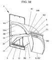
- Fig. 3B
- is a rear perspective view of the hopper structure of fig. 3A;
- Fig. 4A
- is a side view of the hopper unit of figs. 1 and 2 in a loading position;
- Fig. 4B
- is a side view of the hopper unit entering a hopper rear wall activating position;
- Fig. 4C
- is a is a side view of the hopper unit in a discharge position; and
- Fig. 5
- illustrates an alternative embodiment of the cam groove of the transmission in a view corresponding to that of fig. 3A.
- Figs. 1 and 2 illustrate a
hopper unit 2 according to the invention in an application where it is installed in a very schematically depicted receiving body in the shape of awaste chute 1. Thewaste chute 1 is part of a waste collection system that is not illustrated or described in any further detail. Thewaste chute 1 has a waste inlet opening 1A into which thehopper unit 2 is fitted, and said chute may for instance be an isolated ground floor waste chute of a vacuum collection system. Although only the single inlet opening 1A is shown in the drawings, it should be noted that thechute 1 may also be a section of a waste chute of a multi-story building, containing several inlets provided at different levels. - The
hopper unit 2 consists of asupport structure 4 that in this embodiment is aseparate frame 4 that is inserted into theinlet opening 1A and that is attached to thechute 1. Theframe 4 has afront plate 4A that is preferably bolted to the exterior of a chute wall, surrounding theopening 1A. At a rear surface of thefront plate 4A, facing the interior of thechute 1 in the installed condition, a hopper guide structure is provided, consisting of two spacedparallel guide walls 4B that extend into thechute 1. Acover plate 4C upwardly closes off the space between saidguide walls 4B, and serves mainly to stabilize the guide structure. To a certain extent said cover plate in certain applications also protects the hopper unit from items or material falling from a higher level of the chute, such as in the above mentioned waste chute of a multi-story building. - A
hopper structure 3 is pivotally supported in thesupport structure 4, for pivoting around a first horizontal axis H1. Specifically, in the illustrated embodiment, the hopper structure is pivotally supported on apivot pin 12 that is journalled inbrackets 13 attached to the rear of thefront plate 4A. Thehopper structure 3 comprises afront wall 5 having ahandle portion 5A for convenient manual operation of the hopper, as will be described below. Furthermore, two generally sector-shaped, spaced and mutuallyparallel side walls front wall 5, to be received between the twoguide walls 4B of thesupport structure frame 4, each extending adjacent the respective one of the twoguide walls 4B. A rear orbottom wall 8 of thehopper structure 3 is pivotally journalled in theside walls rear portions 6A (only one illustrated in the drawings) thereof being most distant from thefront wall 5. Specifically, adjacent oneend portion 8A thereof therear wall 8 is pivotally supported on apivot pin 11 carried by theside walls rear portions 6A thereof. Thus, as will be described further below therear wall 8 is pivoted between open OC (see figs. 3B and 4C) and closed CC (see fig. 3A) conditions around a second horizontal axis H2. - The pivoting of the
rear wall 8 of thehopper structure 3 between its closed and open conditions CC and OC, respectively, around the second horizontal axis H2 is controlled in dependence upon a pivoting of theentire hopper structure 3 between later described loading and discharge positions LP and DP, respectively (see figs. 4A and 4C). Specifically the pivoting of therear hopper wall 8 is controlled by means of atransmission rear wall 8 to thehopper structure 3 to transmit the pivoting movement of thehopper structure 3 to the rear wall for controlled movement thereof between its closed and open conditions CC and OC, respectively. In the illustrated embodiment the transmission comprises acam follower 9 attached to therear wall 8 at a position spaced from thepivot pin 11 and thereby from the second horizontal pivot axis H2. Here, thecam follower 9 is a pin extending across the full width of therear wall 8 and protruding from the sides of therear wall 8 and into an associatedcam groove 10 extended in each of the twoguide walls 4B of thesupport structure frame 4. Only onecam groove 10 is visible in the drawings, but it should be obvious that the twocam grooves 10 in the twoguide walls 4B are identical both with regard to their positions in theguide walls 4B and to their extension. Thus, each end of thefollower 9 is received in its associatedcam groove 10 in thesupport structure 4 that is fixed relative to thechute 1. - The
cam groove 10 has amain portion 10A extending rearwardly from a position approximately adjacent the rear side of the supportstructure front plate 4A. Themain groove portion 10A is extended at a fixed radius from the first horizontal pivot axis H1. In arear portion 4D of theguide wall 4B, the cam groovemain portion 10A passes into aminor opening portion 10B of thecam groove 10. Compared to themain portion 10A theminor portion 10B has an inverted curvature and a much smaller radius. In other words, theminor groove portion 10B is extended away from the first horizontalpivot axis H 1 at an increasing radial distance therefrom. - Upon movement of the
hopper structure 3 from its loading position LP towards its discharge position DP thefollower 9 will initially travel in the groovemain portion 10A. During this phase, therear wall 8 is maintained in its closed condition CC due to the distance between the pivoting axis H2 of therear wall 8 and thefollower 9. However, further movement of thehopper structure 3 in the same direction will eventually make thecam follower 9 enter theminor opening portion 10B of thegroove 10, allowing thefollower 9 to move away from the first pivot axis H1 and thereby allowing therear wall 8 to swing down to its open condition OC. This operation of thehopper unit 2 will be described further below. - In the illustrated embodiment, the
pivot pin 11 for pivotally supporting therear wall 8 is extended so that it is likewise received in the twogrooves 10, thereby generally stabilizing the pivoting of thehopper structure 3. One or both of the end positions of the pivotal movement of thehopper structure 3 may preferably be determined by the engagement of thepivot pin 11 and/or thecam follower 9 with ends of thecam groove 10, but may alternatively be determined by additional, not illustrated stops. These options will specifically be considered for embodiments lacking the below described damper. - One end of a damper means 20 is pivotally connected to said
extended pivot pin 11 and its opposite end is pivotally connected to abracket 14 attached to the rear side of thefront plate 4A of thesupport structure 4. The purpose of thedamper 20 is to provide damping of the pivoting movement of the hopper structure towards its loading and discharge positions LP and DP, respectively. In particular, it is desirable that thedamper 20 provide progressively increased damping towards said end positions. Such a design will prevent injuries to hands or arms of a person operating the hopper and will also eliminate the risk that hard impacts are produced in the end positions of the hopper structure, caused by a too forceful operation of thehopper structure 3, and will therefore assists in reducing the load on theentire hopper unit 2. Preferably, the desired progressive damping is obtained by means of aviscous damper 20. Although only one damper means is illustrated in the drawings, it should be pointed out that for reasons of stability it is preferred to provide one damper means adjacent eachguide wall 4B. - Fig. 1 illustrates a
restriction plate 15 being extended betweenupper edges hopper side walls front wall 5. Therestriction plate 15 is extended along a limited part of theupper edges side walls support structure 4 as thecam follower 9 enters theminor opening portion 10B of thecam groove 10. The extent to which thehopper structure 3 is still open at the time when therear wall 8 starts to open depends upon the position of the transition of themain groove portion 10A into theminor opening portion 10B of the groove. Said position does in turn depend upon the chosen design for saidopening portion 10B and may be varied for different applications, as will be discussed below. - The purpose of the
restriction plate 15 is to prevent the insertion of longer items into thechute 1, past the openingrear wall 8 during the final pivoting movement of thehopper structure 3 towards its discharge position DP in which the hopperfront wall 5 is positioned so that a rear surface thereof is approximately flush with the outer chute wall. Otherwise, such long items might get stuck in the chute and block the passage therethrough. The illustrated design of thecam groove 10, having a smooth transition between the main andminor groove portions restriction plate 15 will allow for a calm and smooth opening of even a heavy loadedrear wall 8 during the final portion of the hopper closing movement. Still, the introduction of excessively dimensioned items into the receiving body will be effectively inhibited in all operative positions of thehopper 3. - The operation of the
inventive hopper unit 2 will now be described with specific reference to figs 4A-4C. In a loading position LP, as is illustrated in figs. 1, 2 and 4A, the front, side and rear walls, 5, 6, 7 and 8, respectively, of thehopper structure 3 form a receptacle into which a fixed maximum volume of material, such as waste or refuse in the present application, may be inserted. By virtue of the large upper opening of the receptacle that is only restricted by thenarrow restriction plate 15 of this embodiment, waste in the form ofrefuse bags 30 may be conveniently inserted into thehopper structure 3 from straight above. The fixed volume and dimensions of the receptacle inhibits the insertion of too large volumes ofwaste 30 as well as oversized items, both of which might otherwise cause blockage of thechute 1. - When the
hopper 3 has been loaded, thehandle 5A is gripped and the hopper is pivoted into thechute 1 around the first horizontal axis H1. During the first portion of said pivoting, as long as thecam follower 9 remains in themain groove portion 10A, therear hopper wall 8 remains fully closed. Thehopper unit 3 then enters its activating position AP (see fig. 4B) as soon as thecam follower 9 reaches the transition between said main andminor groove portions rear wall 8 between its closed and open conditions CC and OC, respectively, is controlled by the further pivoting of thehopper structure 3 around axis H1 and by the shape of theminor groove portion 10B. In the illustrated embodiment, the shape of theminor groove portion 10B provides a smooth opening of therear wall 8, where the full opening movement thereof is directly controlled by the final pivoting of thehopper 3 around axis H1. - During said pivoting of the
hopper 3 from its loading position LP towards the discharge position DP (see fig. 3) the movement is progressively damped by thedamper 20. Such damping of the movement will prevent injuries to hands or arms in the event that the upper end of the hopperfront wall 5 or therestriction plate 15 is gripped rather than thehandle 5A. Damage to the hopper unit will likewise be avoided since a too forceful closing of the hopper will be excluded, even in case the hopper unit is installed in achute 1 of a vacuum operated waste collection system and the vacuum is applied in the chute when a hopper is in its loading position LP or in any intermediate position. The damper preferably provides progressive damping action in both directions. - Fig. 4C illustrates the
hopper unit 2 in the discharge position DP where thehopper structure 3 has been pivoted to a fully closed position CP and therear wall 8 is in its fully open condition OC so that thewaste 30 will be securely discharged therefrom and into thechute 1. In this open condition OC of therear wall 8 the entire bottom of the receptacle is open, providing a continuously widening discharge passage that favors said discharge and eliminates the risk of blockage. The next time thehopper 3 shall be loaded, thehandle 5A is gripped and thehopper 3 is pivoted back to the loading position LP around the axis H1. During the initial pivoting in this direction, therear wall 8 is likewise pivoted to its closed condition CC by the described interaction between thecam follower 9 and theminor groove portion 10B. - In the illustrated embodiment that is specifically intended for a waste chute application, the total pivoting of the
hopper structure 3 is about 60-70° around the axis H1. In such an application it is advantageous if the hopper is balanced so that it remains in a set position during the first 10-15° of pivoting from the loading position LP, and is then, upon further pivoting, given a self-closing function, even when unloaded, by proper positioning of counterweights (not illustrated). - The shape of the
minor opening portion 10B of thegroove 10 and thereby the length of the pivoting movement of thehopper 3 that is required for actually opening the hopperrear wall 8, depends to a large extent upon the desired characteristics of the opening and closing of therear wall 8. Fig. 5 illustrates a modified embodiment of the invention, where thesupport structure 104, and specifically itsguide walls 104B, have been slightly re-designed to accommodate a modifiedgroove 110. Specifically, themain groove portion 110A has been extended in order to maintain the hopperrear wall 8 in its closed position until shortly before the hopperfront wall 5 engages thefront plate 104A of thesupport structure 104. The minorclosing groove portion 110B as well as the transition between the main and major groove portions have also been modified to provide a steep short radius transition between the main andminor groove portions rear wall 8 at the very end of the pivoting of thehopper 3 towards its discharge position DP. - However, such a design will in most cases necessitate the use of means for damping the opening movement of the
rear wall 8, in order to avoid harmful impacts caused by a rapid opening of the rear wall. Additional forces may also be required when therear wall 8 shall be closed during the initial hopper movement from the discharge position DP. In such an embodiment the hopper unit would therefore in most cases also have to be supplemented with an actuator (not illustrated) assisting in returning thehopper structure 3 to its loading position LP by initiating the closing movement of therear wall 8. Thus, the invention covers all practically possible shapes and designs of the guide groove and its main and minor portions. - In a further alternative embodiment, not specifically illustrated, it is also possible to provide the guide groove in one or both of the hopper side walls and to provide a cam follower on the inner side of one or both guide walls of the support structure. In such a case the groove would be inverted, having the opening groove portion positioned closer to the hopper front wall.
- In all of the illustrated and described embodiments of the invention, the hopper structure has been supported in a separate frame attached to the receiving body. It should be emphasized though, that the invention likewise covers embodiments, not specifically illustrated, wherein said hopper-supporting frame is an integral part of the receiving body. Furthermore, it should be pointed out that the invention covers also transmission grooves provided in either or both guide walls of the frame and cooperating with a corresponding single-sided or double-sided cam follower.
- It will be understood by those skilled in the art that various modifications and changes may be made to the present invention without departure from the scope thereof, which is defined by the appended claims.
Claims (15)
- A hopper unit (2) for loading material into a receiving body (1), comprising a hopper structure (3) having walls (5, 6, 7, 8) forming a fixed volume receptacle in a loading position (LP) of the hopper structure, and a support structure (4; 104) pivotally supporting the hopper structure for pivoting between the loading position and a discharge position (DP) around a first horizontal axis (H1), characterized in that one wall (8) of the hopper structure is pivotally connected to fixed hopper walls (6, 7), for movement around a second horizontal axis (H2) between a closed and an open condition (CC and OC, respectively) and by a transmission (9, 10; 110) functionally connecting the pivotal wall to the pivoting movement of the hopper structure (3) between the loading and discharge positions (LP and DP, respectively) to thereby transmit said hopper structure movement to the rear wall for controlled movement thereof between its closed and open conditions (CC and OC, respectively).
- A hopper unit (2) according to claim 1, characterized in that the hopper structure (3) has a front wall (5), spaced side walls (6, 7) and a pivotal rear wall (8), in that the support structure (4; 104) is stationary, in that the rear wall (8) is pivotally connected adjacent one end (8A) thereof to the side walls (6, 7), for movement around the second horizontal axis (H2) and in that the transmission (9, 10; 110) physically connects the rear wall (8) to the support structure (4; 104).
- A hopper unit (2) according to claim 2, characterized in that the transmission comprises at least one cam follower (9) attached to the rear wall (8) at a position spaced from the second horizontal pivot axis (H2) and at least one cam groove (10; 110) in the support structure (4; 104), receiving said at least one cam follower (9).
- A hopper unit (2) according to claim 3, characterized in that a main portion (10A; 110A) of the cam groove (10; 110) is extended at a fixed radius from the first horizontal pivot axis (H1) and in that a minor opening portion (10B; 110B) of the cam groove is extended away from the first horizontal pivot axis (H1) at an increasing radial distance therefrom.
- A hopper unit (2) according to any of claims 2-4, characterized by a restriction plate (15) being extended between upper edges (6B, 7B) of the hopper side walls (6, 7) at a position immediately adjacent the hopper front wall (5).
- A hopper unit (2) according to claim 5, characterized in that the restriction plate (15) is extended along a limited part of the upper edges (6B, 7B) of the side walls (6,7), said limited part being substantially equal to the part of said upper edges being positioned outside the support structure (4; 104) as the cam follower (9) enters the opening portion (10B; 110B) of the cam groove (10; 110).
- A hopper unit (2) according to any of claims 1-6, characterized by a damper means (20) being extended between the support structure (4; 104) and the hopper structure (3) for providing progressive damping of said pivoting movement of the latter towards its loading and/or discharge positions (LP and DP, respectively).
- A hopper unit (2) according to claim 7, characterised in that the damper means is a viscous damper (20) extended between the support structure (4; 104) and a pivot pin (11) for supporting the rear wall (8) for pivoting around said second horizontal axis (H2).
- A method of controlling the emptying of a hopper unit (2) that is employed for loading material into a receiving body (1) and that comprises a hopper structure (3) having walls (5, 6, 7, 8) forming a fixed volume receptacle in a loading position (LP) of the hopper structure, and a support structure (4) for pivotally supporting the hopper structure for pivoting between the loading position and a discharge position (DP) around a first horizontal axis (H1), characterized by pivoting one wall (8) of the hopper structure around a second horizontal axis (H2) between a closed and an open condition (CC and OC, respectively) and by controlling the movement of the pivotal wall in dependence upon the pivoting of the hopper structure (3) between the loading and discharge positions (LP and DP, respectively).
- A method according to claim 9, characterized by controlling the movement of the pivotal wall (8) around the second horizontal axis (H2) during its full movement between the closed and open conditions (CC and OC, respectively).
- A method according to claim 9 or 10, characterized by progressively damping the movement of the hopper structure (3) towards its loading and/or discharge positions (LP and DP, respectively).
- A waste chute (1) having at least one inlet opening (1A), a hopper unit (2) for loading material into the chute being provided in the or each inlet opening, said hopper unit comprising a support structure (4) being fixed relative to the chute and a hopper structure (3) being pivotally supported in the support structure for pivoting around a first horizontal axis (H1) between a loading position (LP) and a discharge position (DP) and having walls (5, 6, 7, 8) forming a fixed volume receptacle in the loading position, characterized in that one wall (8) of the hopper structure is pivotally connected to fixed hopper walls (6, 7), for movement around a second horizontal axis (H2) between a closed condition (CC) wherein it completes the fixed volume receptacle and an open condition (OC) wherein it opens the receptacle for discharge of the volume of material into the chute and by a transmission (9, 10) functionally connecting the pivotal wall to the pivoting movement of the hopper structure (3) between the loading and discharge positions (LP and DP, respectively) to thereby transmit said hopper structure movement to the rear wall for controlled movement thereof between its closed and open conditions.
- A waste chute (1) according to claim 12, characterized in that the hopper structure (3) has a front wall (5), spaced side walls (6, 7) and a pivotal rear wall (8), in that the support structure (4; 104) is fixed to the chute 1, in that the rear wall (8) is pivotally connected adjacent one end (8A) thereof to the side walls (6, 7), for movement around the second horizontal axis (H2) and in that the transmission (9, 10; 110) physically connects the rear wall (8) to the stationary support structure (4; 104).
- A waste chute (1) according to claim 12 or 13, characterized in that the support structure (4) is a separate frame attached to the chute (1).
- A waste chute (1) according to claim 12 or 13, characterized in that the support structure (4) is an integral part of the chute (1).
Applications Claiming Priority (1)
| Application Number | Priority Date | Filing Date | Title |
|---|---|---|---|
| PCT/SE2003/000517 WO2004087538A1 (en) | 2003-03-31 | 2003-03-31 | Hopper structure, method of controlling the emptying of such a hopper structure, and a waste chute having such a hopper structure |
Publications (2)
| Publication Number | Publication Date |
|---|---|
| EP1611035A1 EP1611035A1 (en) | 2006-01-04 |
| EP1611035B1 true EP1611035B1 (en) | 2006-07-26 |
Family
ID=33129401
Family Applications (1)
| Application Number | Title | Priority Date | Filing Date |
|---|---|---|---|
| EP03713159A Expired - Lifetime EP1611035B1 (en) | 2003-03-31 | 2003-03-31 | Hopper structure, method of controlling the emptying of such a hopper structure, and a waste chute having such a hopper structure |
Country Status (8)
| Country | Link |
|---|---|
| EP (1) | EP1611035B1 (en) |
| AT (1) | ATE334082T1 (en) |
| AU (1) | AU2003217126A1 (en) |
| DE (1) | DE60307146D1 (en) |
| DK (1) | DK1611035T3 (en) |
| ES (1) | ES2268342T3 (en) |
| PT (1) | PT1611035E (en) |
| WO (1) | WO2004087538A1 (en) |
Families Citing this family (5)
| Publication number | Priority date | Publication date | Assignee | Title |
|---|---|---|---|---|
| FR2957066B1 (en) * | 2010-03-03 | 2012-04-13 | Plastic Omnium Cie | RECEPTACLE FOR WASTE COLLECTION CONTAINER, SUITABLE FOR BIG PRODUCERS |
| DE102010046852B4 (en) * | 2010-09-29 | 2016-01-14 | Emz-Hanauer Gmbh & Co. Kgaa | Waste lock and garbage container |
| DE202012102398U1 (en) * | 2012-06-28 | 2013-09-30 | Paul Wolff Gmbh | Enclosure of a subterranean waste collection container |
| FR3064932B1 (en) * | 2017-04-07 | 2019-06-14 | Axibio | FOOD HOPPER |
| IT201900002951A1 (en) * | 2019-02-28 | 2020-08-28 | Nord Eng S R L | CONTAINER FOR THE COLLECTION OF WASTE INCLUDING AN IMPROVED DISTRIBUTION DEVICE |
Family Cites Families (4)
| Publication number | Priority date | Publication date | Assignee | Title |
|---|---|---|---|---|
| US1733801A (en) * | 1927-04-13 | 1929-10-29 | Harry H Heybeck | Refuse-incinerator construction and hopper door therefor |
| US1755089A (en) * | 1927-09-14 | 1930-04-15 | Robert T Wyse | Chimney hopper for incinerators |
| GB1231007A (en) * | 1968-03-08 | 1971-05-05 | ||
| FR2264940A1 (en) * | 1974-03-22 | 1975-10-17 | Pottier Freres Ets | Waste-disposal unit with flap-door - has pivotal bucket in housing closed by a door opening onto waste pipe |
-
2003
- 2003-03-31 AT AT03713159T patent/ATE334082T1/en not_active IP Right Cessation
- 2003-03-31 ES ES03713159T patent/ES2268342T3/en not_active Expired - Lifetime
- 2003-03-31 AU AU2003217126A patent/AU2003217126A1/en not_active Abandoned
- 2003-03-31 WO PCT/SE2003/000517 patent/WO2004087538A1/en not_active Ceased
- 2003-03-31 PT PT03713159T patent/PT1611035E/en unknown
- 2003-03-31 DK DK03713159T patent/DK1611035T3/en active
- 2003-03-31 EP EP03713159A patent/EP1611035B1/en not_active Expired - Lifetime
- 2003-03-31 DE DE60307146T patent/DE60307146D1/en not_active Expired - Lifetime
Also Published As
| Publication number | Publication date |
|---|---|
| EP1611035A1 (en) | 2006-01-04 |
| ES2268342T3 (en) | 2007-03-16 |
| WO2004087538A1 (en) | 2004-10-14 |
| PT1611035E (en) | 2006-12-29 |
| DK1611035T3 (en) | 2006-11-20 |
| AU2003217126A1 (en) | 2004-10-25 |
| ATE334082T1 (en) | 2006-08-15 |
| DE60307146D1 (en) | 2006-09-07 |
Similar Documents
| Publication | Publication Date | Title |
|---|---|---|
| US6626317B2 (en) | Opening device for a garbage can having two hinged lid segments | |
| US8944276B2 (en) | Dumpster with a moveable false floor and method of collecting trash using the same | |
| US5248057A (en) | Versatile double actuation trash container lid | |
| EP1948536B1 (en) | Waste bin | |
| EP1611035A1 (en) | Hopper structure, method of controlling the emptying of such a hopper structure, and a waste chute having such a hopper structure | |
| US5215365A (en) | Concealable trash receptacle | |
| US20090261696A1 (en) | Cabinet-shaped piece of furniture | |
| US5595317A (en) | Lid prop for commercial trash bin | |
| CA2312314A1 (en) | Self-rising door handle | |
| EP2345604A1 (en) | Insertion column for a bulk material container | |
| EP1063153A3 (en) | An arrangement of a damper for controlling opening and closing movement of a vehicle seat | |
| AU4628599A (en) | Tipper for collecting and transporting a load such as household refuse | |
| JP5832231B2 (en) | Dust input device and dust storage system | |
| CN211287182U (en) | Positioning opening and closing structure of folding sliding door | |
| CN2715069Y (en) | An ice making machine | |
| AU2008200939B2 (en) | Bin Latch | |
| US6793451B2 (en) | Garbage or recyclable materials handling container | |
| JP2826212B2 (en) | Door stop device | |
| CN222555666U (en) | A road trash can | |
| JP2719958B2 (en) | Garbage suction truck | |
| CN219030576U (en) | garbage can | |
| CN215794769U (en) | Automatic metering racking machine | |
| GB2077695A (en) | Bin raising and tipping mechanisms | |
| AU768586B2 (en) | Two way hydraulic door side tipper | |
| GB2402043A (en) | Pivotal mounting of waste container lid |
Legal Events
| Date | Code | Title | Description |
|---|---|---|---|
| PUAI | Public reference made under article 153(3) epc to a published international application that has entered the european phase |
Free format text: ORIGINAL CODE: 0009012 |
|
| 17P | Request for examination filed |
Effective date: 20051031 |
|
| AK | Designated contracting states |
Kind code of ref document: A1 Designated state(s): AT BE BG CH CY CZ DE DK EE ES FI FR GB GR HU IE IT LI LU MC NL PT RO SE SI SK TR |
|
| AX | Request for extension of the european patent |
Extension state: AL LT LV MK |
|
| GRAP | Despatch of communication of intention to grant a patent |
Free format text: ORIGINAL CODE: EPIDOSNIGR1 |
|
| GRAS | Grant fee paid |
Free format text: ORIGINAL CODE: EPIDOSNIGR3 |
|
| GRAA | (expected) grant |
Free format text: ORIGINAL CODE: 0009210 |
|
| DAX | Request for extension of the european patent (deleted) | ||
| AK | Designated contracting states |
Kind code of ref document: B1 Designated state(s): AT BE BG CH CY CZ DE DK EE ES FI FR GB GR HU IE IT LI LU MC NL PT RO SE SI SK TR |
|
| PG25 | Lapsed in a contracting state [announced via postgrant information from national office to epo] |
Ref country code: IT Free format text: LAPSE BECAUSE OF FAILURE TO SUBMIT A TRANSLATION OF THE DESCRIPTION OR TO PAY THE FEE WITHIN THE PRESCRIBED TIME-LIMIT;WARNING: LAPSES OF ITALIAN PATENTS WITH EFFECTIVE DATE BEFORE 2007 MAY HAVE OCCURRED AT ANY TIME BEFORE 2007. THE CORRECT EFFECTIVE DATE MAY BE DIFFERENT FROM THE ONE RECORDED. Effective date: 20060726 Ref country code: BE Free format text: LAPSE BECAUSE OF FAILURE TO SUBMIT A TRANSLATION OF THE DESCRIPTION OR TO PAY THE FEE WITHIN THE PRESCRIBED TIME-LIMIT Effective date: 20060726 Ref country code: AT Free format text: LAPSE BECAUSE OF FAILURE TO SUBMIT A TRANSLATION OF THE DESCRIPTION OR TO PAY THE FEE WITHIN THE PRESCRIBED TIME-LIMIT Effective date: 20060726 Ref country code: FI Free format text: LAPSE BECAUSE OF FAILURE TO SUBMIT A TRANSLATION OF THE DESCRIPTION OR TO PAY THE FEE WITHIN THE PRESCRIBED TIME-LIMIT Effective date: 20060726 Ref country code: RO Free format text: LAPSE BECAUSE OF FAILURE TO SUBMIT A TRANSLATION OF THE DESCRIPTION OR TO PAY THE FEE WITHIN THE PRESCRIBED TIME-LIMIT Effective date: 20060726 Ref country code: LI Free format text: LAPSE BECAUSE OF FAILURE TO SUBMIT A TRANSLATION OF THE DESCRIPTION OR TO PAY THE FEE WITHIN THE PRESCRIBED TIME-LIMIT Effective date: 20060726 Ref country code: NL Free format text: LAPSE BECAUSE OF FAILURE TO SUBMIT A TRANSLATION OF THE DESCRIPTION OR TO PAY THE FEE WITHIN THE PRESCRIBED TIME-LIMIT Effective date: 20060726 Ref country code: SI Free format text: LAPSE BECAUSE OF FAILURE TO SUBMIT A TRANSLATION OF THE DESCRIPTION OR TO PAY THE FEE WITHIN THE PRESCRIBED TIME-LIMIT Effective date: 20060726 Ref country code: CH Free format text: LAPSE BECAUSE OF FAILURE TO SUBMIT A TRANSLATION OF THE DESCRIPTION OR TO PAY THE FEE WITHIN THE PRESCRIBED TIME-LIMIT Effective date: 20060726 Ref country code: SK Free format text: LAPSE BECAUSE OF FAILURE TO SUBMIT A TRANSLATION OF THE DESCRIPTION OR TO PAY THE FEE WITHIN THE PRESCRIBED TIME-LIMIT Effective date: 20060726 Ref country code: CZ Free format text: LAPSE BECAUSE OF FAILURE TO SUBMIT A TRANSLATION OF THE DESCRIPTION OR TO PAY THE FEE WITHIN THE PRESCRIBED TIME-LIMIT Effective date: 20060726 |
|
| REG | Reference to a national code |
Ref country code: GB Ref legal event code: FG4D |
|
| REG | Reference to a national code |
Ref country code: CH Ref legal event code: EP |
|
| REG | Reference to a national code |
Ref country code: IE Ref legal event code: FG4D |
|
| REF | Corresponds to: |
Ref document number: 60307146 Country of ref document: DE Date of ref document: 20060907 Kind code of ref document: P |
|
| REG | Reference to a national code |
Ref country code: SE Ref legal event code: TRGR |
|
| PG25 | Lapsed in a contracting state [announced via postgrant information from national office to epo] |
Ref country code: BG Free format text: LAPSE BECAUSE OF FAILURE TO SUBMIT A TRANSLATION OF THE DESCRIPTION OR TO PAY THE FEE WITHIN THE PRESCRIBED TIME-LIMIT Effective date: 20061026 |
|
| PG25 | Lapsed in a contracting state [announced via postgrant information from national office to epo] |
Ref country code: DE Free format text: LAPSE BECAUSE OF FAILURE TO SUBMIT A TRANSLATION OF THE DESCRIPTION OR TO PAY THE FEE WITHIN THE PRESCRIBED TIME-LIMIT Effective date: 20061027 |
|
| REG | Reference to a national code |
Ref country code: DK Ref legal event code: T3 |
|
| REG | Reference to a national code |
Ref country code: PT Ref legal event code: SC4A Free format text: AVAILABILITY OF NATIONAL TRANSLATION Effective date: 20061016 |
|
| NLV1 | Nl: lapsed or annulled due to failure to fulfill the requirements of art. 29p and 29m of the patents act | ||
| ET | Fr: translation filed | ||
| REG | Reference to a national code |
Ref country code: ES Ref legal event code: FG2A Ref document number: 2268342 Country of ref document: ES Kind code of ref document: T3 |
|
| PLBE | No opposition filed within time limit |
Free format text: ORIGINAL CODE: 0009261 |
|
| STAA | Information on the status of an ep patent application or granted ep patent |
Free format text: STATUS: NO OPPOSITION FILED WITHIN TIME LIMIT |
|
| 26N | No opposition filed |
Effective date: 20070427 |
|
| GBPC | Gb: european patent ceased through non-payment of renewal fee |
Effective date: 20070331 |
|
| PG25 | Lapsed in a contracting state [announced via postgrant information from national office to epo] |
Ref country code: MC Free format text: LAPSE BECAUSE OF NON-PAYMENT OF DUE FEES Effective date: 20070331 |
|
| PG25 | Lapsed in a contracting state [announced via postgrant information from national office to epo] |
Ref country code: GR Free format text: LAPSE BECAUSE OF FAILURE TO SUBMIT A TRANSLATION OF THE DESCRIPTION OR TO PAY THE FEE WITHIN THE PRESCRIBED TIME-LIMIT Effective date: 20061027 Ref country code: GB Free format text: LAPSE BECAUSE OF NON-PAYMENT OF DUE FEES Effective date: 20070331 |
|
| PG25 | Lapsed in a contracting state [announced via postgrant information from national office to epo] |
Ref country code: IE Free format text: LAPSE BECAUSE OF NON-PAYMENT OF DUE FEES Effective date: 20070402 |
|
| PG25 | Lapsed in a contracting state [announced via postgrant information from national office to epo] |
Ref country code: EE Free format text: LAPSE BECAUSE OF FAILURE TO SUBMIT A TRANSLATION OF THE DESCRIPTION OR TO PAY THE FEE WITHIN THE PRESCRIBED TIME-LIMIT Effective date: 20060726 |
|
| PG25 | Lapsed in a contracting state [announced via postgrant information from national office to epo] |
Ref country code: LU Free format text: LAPSE BECAUSE OF NON-PAYMENT OF DUE FEES Effective date: 20070331 Ref country code: CY Free format text: LAPSE BECAUSE OF FAILURE TO SUBMIT A TRANSLATION OF THE DESCRIPTION OR TO PAY THE FEE WITHIN THE PRESCRIBED TIME-LIMIT Effective date: 20060726 |
|
| PG25 | Lapsed in a contracting state [announced via postgrant information from national office to epo] |
Ref country code: HU Free format text: LAPSE BECAUSE OF FAILURE TO SUBMIT A TRANSLATION OF THE DESCRIPTION OR TO PAY THE FEE WITHIN THE PRESCRIBED TIME-LIMIT Effective date: 20070127 Ref country code: TR Free format text: LAPSE BECAUSE OF FAILURE TO SUBMIT A TRANSLATION OF THE DESCRIPTION OR TO PAY THE FEE WITHIN THE PRESCRIBED TIME-LIMIT Effective date: 20060726 |
|
| REG | Reference to a national code |
Ref country code: FR Ref legal event code: PLFP Year of fee payment: 13 |
|
| REG | Reference to a national code |
Ref country code: FR Ref legal event code: PLFP Year of fee payment: 14 |
|
| PGFP | Annual fee paid to national office [announced via postgrant information from national office to epo] |
Ref country code: SE Payment date: 20160323 Year of fee payment: 14 |
|
| REG | Reference to a national code |
Ref country code: FR Ref legal event code: PLFP Year of fee payment: 15 |
|
| PGFP | Annual fee paid to national office [announced via postgrant information from national office to epo] |
Ref country code: FR Payment date: 20170320 Year of fee payment: 15 |
|
| PGFP | Annual fee paid to national office [announced via postgrant information from national office to epo] |
Ref country code: PT Payment date: 20170316 Year of fee payment: 15 |
|
| PGFP | Annual fee paid to national office [announced via postgrant information from national office to epo] |
Ref country code: IT Payment date: 20170314 Year of fee payment: 15 Ref country code: ES Payment date: 20170317 Year of fee payment: 15 |
|
| PG25 | Lapsed in a contracting state [announced via postgrant information from national office to epo] |
Ref country code: SE Free format text: LAPSE BECAUSE OF NON-PAYMENT OF DUE FEES Effective date: 20170401 |
|
| PG25 | Lapsed in a contracting state [announced via postgrant information from national office to epo] |
Ref country code: PT Free format text: LAPSE BECAUSE OF NON-PAYMENT OF DUE FEES Effective date: 20181001 |
|
| PG25 | Lapsed in a contracting state [announced via postgrant information from national office to epo] |
Ref country code: IT Free format text: LAPSE BECAUSE OF NON-PAYMENT OF DUE FEES Effective date: 20180331 |
|
| PG25 | Lapsed in a contracting state [announced via postgrant information from national office to epo] |
Ref country code: FR Free format text: LAPSE BECAUSE OF NON-PAYMENT OF DUE FEES Effective date: 20180331 |
|
| REG | Reference to a national code |
Ref country code: ES Ref legal event code: FD2A Effective date: 20190911 |
|
| PG25 | Lapsed in a contracting state [announced via postgrant information from national office to epo] |
Ref country code: ES Free format text: LAPSE BECAUSE OF NON-PAYMENT OF DUE FEES Effective date: 20180401 |
|
| PGFP | Annual fee paid to national office [announced via postgrant information from national office to epo] |
Ref country code: DK Payment date: 20200325 Year of fee payment: 18 |
|
| REG | Reference to a national code |
Ref country code: DK Ref legal event code: EBP Effective date: 20210331 |
|
| PG25 | Lapsed in a contracting state [announced via postgrant information from national office to epo] |
Ref country code: DK Free format text: LAPSE BECAUSE OF NON-PAYMENT OF DUE FEES Effective date: 20210331 |