EP1610445A1 - Device and method for manufacture of rotating electric machine - Google Patents
Device and method for manufacture of rotating electric machine Download PDFInfo
- Publication number
- EP1610445A1 EP1610445A1 EP04787875A EP04787875A EP1610445A1 EP 1610445 A1 EP1610445 A1 EP 1610445A1 EP 04787875 A EP04787875 A EP 04787875A EP 04787875 A EP04787875 A EP 04787875A EP 1610445 A1 EP1610445 A1 EP 1610445A1
- Authority
- EP
- European Patent Office
- Prior art keywords
- varnish
- wire
- electric machine
- work
- wound coils
- Prior art date
- Legal status (The legal status is an assumption and is not a legal conclusion. Google has not performed a legal analysis and makes no representation as to the accuracy of the status listed.)
- Withdrawn
Links
Images








Classifications
-
- H—ELECTRICITY
- H02—GENERATION; CONVERSION OR DISTRIBUTION OF ELECTRIC POWER
- H02K—DYNAMO-ELECTRIC MACHINES
- H02K15/00—Processes or apparatus specially adapted for manufacturing, assembling, maintaining or repairing of dynamo-electric machines
- H02K15/12—Impregnating, moulding insulation, heating or drying of windings, stators, rotors or machines
-
- H—ELECTRICITY
- H02—GENERATION; CONVERSION OR DISTRIBUTION OF ELECTRIC POWER
- H02K—DYNAMO-ELECTRIC MACHINES
- H02K1/00—Details of the magnetic circuit
- H02K1/02—Details of the magnetic circuit characterised by the magnetic material
-
- H—ELECTRICITY
- H02—GENERATION; CONVERSION OR DISTRIBUTION OF ELECTRIC POWER
- H02K—DYNAMO-ELECTRIC MACHINES
- H02K1/00—Details of the magnetic circuit
- H02K1/06—Details of the magnetic circuit characterised by the shape, form or construction
- H02K1/12—Stationary parts of the magnetic circuit
- H02K1/18—Means for mounting or fastening magnetic stationary parts on to, or to, the stator structures
- H02K1/185—Means for mounting or fastening magnetic stationary parts on to, or to, the stator structures to outer stators
Definitions
- This invention relates to manufacturing a rotary electric machine such as an electric motor, a generator and an electric motor-generator. Specifically, this invention pertains to a technology fixing, by curing infiltrated varnish, wire-wound coils of a rotary electric machine.
- a varnish-infiltrating process exists by which a varnish is applied to wire-wound coils and is then cured, in such a manner as to reinforce an insulating performance of wire-wound coils inserted into slots of such a stator, and to enhance their anti-vibration characteristics, their oil resistance, their chemical resistance, and their heat-radiating performance.
- this varnish-infiltrating process aside from a varnish-dropping process, there are processes of pre-drying, gelating, and curing, as processes accompanying a heat-up process for a pre-processing and for an after-processing.
- a varnish dropping-infiltrating treatment is performed, for the purpose of preventing a varnish from being attached to the inside and outside of a core, so as to drop a varnish onto only coil ends and portions that stand up from slots while a work is being rotated.
- processes of pre-drying in which moisture is removed and a degree of coil stress is modified
- curing in which, in order to prevent a varnish from weeping, a varnish is cured or hardened while a work is being rotated.
- a method of heating up through these processes there is a method according to which an oven or a hot blast-circulating furnace is employed.
- Patent Document 1 JP07(1995)-031108A
- a rotary electric machine-manufacturing apparatus by means of which, and a method of manufacturing a rotary electric machine, according to which, it is possible to rotate a work while electric current is being supplied to the work, and to enhance working efficiency, in a manner such that, through a series of processes of infiltrating varnish into wire-wound coils and curing the varnish at an event of manufacturing a rotary electric machine, in a condition where the work has been set, pre-drying, varnish dropping, and curing can be continuously performed for a short time.
- a rotary electric machine-manufacturing apparatus utilized to implement a process of infiltrating varnish into wire-wound coils of a rotary electric machine, and of curing the varnish
- the apparatus is characterized in including a rotator supporting a work attached with the wire-wound coils and rotating the work; a power supply device supplying electric power to the wire-wound coils; and a varnish-infiltrating device supplying varnish to the wire-wound coils.
- Electric supply lines connecting the power supply device with the wire-wound coils of the work are linked by a slip ring.
- a rotary electric machine-manufacturing apparatus utilized to implement a process of infiltrating varnish into wire-wound coils of a rotary electric machine, and of curing the varnish
- the apparatus is characterized in having a rotator supporting a work attached with the wire-wound coils and rotating the work; a power supply device supplying electric power to the wire-wound coils; and a varnish-infiltrating device supplying varnish to the wire-wound coils.
- the rotator is a reciprocatingly rotating device that reciprocatingly rotates in a first rotational direction and in an opposite rotational direction.
- a method of manufacturing a rotary electric machine including a process infiltrating a varnish into wire-wound coils of a rotary electric machine, and of curing the varnish is characterized in supplying varnish to wire-wound coils while electric power is being supplied to the wire-wound coils together with continuously rotating a work, which has been attached with the wire-wound coils and has been supported, in a rotational direction.
- a method of manufacturing a rotary electric machine including a process infiltrating a varnish into wire-wound coils of a rotary electric machine, and of curing the varnish is characterized in supplying varnish to wire-wound coils while electric power is being supplied to the wire-wound coils together with reciprocating rotation of a work, which has been attached with the wire-wound coils and has been supported, in a first rotational direction and in an opposite rotational direction.
- the work can be rotated continuously or reciprocatingly while electric current is being supplied to the work. Therefore, it is possible to perfume a varnish-dropping process while a temperature of the work is being maintained at an optimum level by controlling electric power supply.
- a varnish-infiltrating device it is possible to implement all kinds of processes of pre-drying, dropping, gelating, and curing, which are contained in a varnish-infiltrating process.
- the rotator is a reciprocatingly rotating device
- electric supply lines from the power supply device are supported by an electric supply line twist-inhibiting mechanism. In this case, it is possible to avoid disturbances of the electric supply lines, disturbances that may occur due to reciprocating rotation of the reciprocating rotating device.
- a power supply device supplying electric power to the wire wound coils is a high-frequency power supply device which supplies high-frequency electric power of which a frequency is higher than a level of a frequency of a commercial power source.
- a power supply device supplies high-frequency electric power of which a frequency is higher than a level of a frequency of a commercial power source, as explained above.
- a commercial power source is deemed to be a source of electric power at a level of frequency of 50Hz or 60Hz, electric power supplied by an electric power supplier, or another electric power source being comparable to the aforementioned source.
- a commercial three-phase type power source which emanates three-phase electric power for commercial uses, is deemed to fall into the category of such a commercial power source.
- the power supply device of the present invention can be applied to all kinds of processes included in a process of infiltrating a varnish to wire-wound coils of a rotary electric machine and of curing the varnish, processes which are a pre-drying process, a gelating process, according to which the varnish that has been infiltrated is gelated, and a curing process, according to which the varnish is cured or hardened.
- processes which are a pre-drying process, a gelating process, according to which the varnish that has been infiltrated is gelated, and a curing process, according to which the varnish is cured or hardened Especially, it is particularly effective if the power supply device of the present invention were applied to a varnish dropping-infiltrating process, through which a work is preferably rotated.
- a work is rotated while supported at a radially inner side thereof.
- a work is rotated while supported at a radially inner side thereof.
- the reciprocatingly rotating device reciprocatingly repeats rotation of a work at 360 degrees or more in a rotational direction. It is thus possible to minimize the number of varnish-supplying means provided at a varnish-infiltrating device, and thereby downsizing a rotary electric machine-manufacturing apparatus according to the present invention.
- the reciprocatingly rotating device can reciprocatingly repeat rotation of the work at a rotational angle within a rotational angle range of between 180 degrees or more and up to less than 360 degrees in a rotational direction.
- the varnish-supplying means of the varnish-infiltrating device are installed at least at two positions every single target portion for the application of varnish to wire-wound coils.
- Each target portion for the application of varnish to the wire-wound coils is, for example, an outer peripheral surface, or an inner peripheral surface, at each coil end.
- the varnish-supplying means can be installed and rotated, so as not to interfere with other components such as coil terminals and connector electric supply lines.
- the varnish-supplying means supply varnish to inner peripheral surfaces of coil ends at a coil terminal side
- the varnish-supplying means can be installed so as to extend from an outer side of the coils.
- the work is to be supported at the radially inner side thereof, it is possible to prevent varnish from becoming attached to a member supporting the work.
- the reciprocatingly rotating device can also reciprocatingly repeat rotation of a work at a rotational angle within a rotational angle range of between 120 degrees or more and up to less than 180 degrees in a rotational direction.
- the varnish-supplying means of the varnish-infiltrating device are installed at least at three positions every single target portion for the application of varnish to the wire wound coils.
- the varnish-supplying means in addition to a conventional type that drops varnish in a vertical direction from nozzles, for example, an injector-type, which discharges varnish by use of an injector, and a coater roll-type, which transfers and applies varnish from a coater roll that has raised the varnish, can be employed.
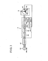
- FIGs. 1 and 2 illustrate a rotary electric machine-manufacturing apparatus according to a first embodiment.
- this apparatus has a structure made up of a rotator 2 on a device table 1, a chuck 3 serving as a work-supporting means attached to the rotator 2, a high-frequency power supply device that is provided separately and is not shown, and a work outer periphery-supporting means 5.
- a varnish dropping-infiltrating device 6 is positioned and supported by a base frame that is different from the device table 1, and dropping nozzles 61 of the varnish dropping-infiltrating device 6 extend vertically towards a work S.
- the rotator 2 is configured with a main shaft 20, of which both ends are freely rotatably supported by bearings 11 at the device table 1, and a motor 22 which is activated to reciprocatingly rotate the main shaft 20 via a transmission mechanism 21 at one side of the main shaft 20.
- the transmission mechanism 21 according to the first embodiment is configured with a belt transmission mechanism having a timing belt and a pulley.
- an electric supply line twist-inhibiting mechanism 70 is positioned between the bearings 11 supporting the main shaft 20.
- the electric supply line twist-inhibiting mechanism 70 includes a cable bare.
- the electric supply lines 7 from the power supply device are supported by the electric supply line twist-inhibiting mechanism 70.
- the chuck 3 is equipped at the other end of the main shaft 20, the chuck 3 which holds the work S from an inner diameter side thereof.
- a reverse rotational position can be varied arbitrarily by intervals of 10 degrees within a range of 0 - 360 degrees in terms of a reverse rotational angle.
- the work outer periphery-supporting means 5 is positioned below the work 2.
- a tray 62, which receives varnish, is provided inside a base frame of the work outer periphery-supporting means 5.
- the high-frequency power supply device 4 is connected to a commercial three-phase electric power source 40 of 200V via a noise-canceling transformer 41.
- This type of high-frequency power supply device 4 converts, to a direct electric current, a three-phase electric current that excludes any waveform disturbances resulting from noise canceling.
- this type of high-frequency power supply device 4 is provided with a rectifier 42 having, for example, a converter, a smoother 43 having, for example, a condenser, and a high-frequency generator 44 having, for example, an inverter.
- the smoother 43 is employed for the purpose of smoothing a pulsating flow rectified by the rectifier 42.
- the high-frequency generator 44 converts, to a high-frequency electric current at a single-phase frequency level of approximately 20kHz, the direct electric current smoothed by the smoother 43.
- This high-frequency generator 44 is controlled by a controller 45, which is connected to, for example, a temperature information obtaining means 46, and a condition inputting means 47 that inputs heat-up conditions, in a manner such that temperature information and controlling conditions are input into the controller 45.
- the temperature information obtaining means 46 has, as a detecting element, a thermistor embedded in wire-wound coils Sc.
- the reference “S” refers to, as a work S that is an object of processing, a stator in which the wire-wound coils Sc have been inserted.
- the high frequency power supply device 4 and the wire-wound coils Sc of the work S can be connected to each other via the electric supply lines 7.
- the chuck 3 supports a three-phase connector 71 of the three electric supply lines 7 from the high-frequency power supply device 4.
- a wire connecting means provided with a connector 72 fitted into the connector 71 can be attached to the chuck 3.
- This wire connecting means is configured with a terminal table 73 having three-phase junction terminals.
- This terminal table 73 includes a reverse C-shaped mounting bracket, and the three-phase junction terminals that are made from electric conductors fixedly mounted on the mounting bracket via an insulating material.
- the mounting bracket possesses boltholes at its leg portions, boltholes that are employed so as to attach to the chuck 3.
- Each junction terminal is connected, via electric leads 74, to the connector 72 on the terminal table 73 side.
- Each junction terminal is provided with a connecting portion that is freely attached to, and detached from, each lead terminal of each wire-wound coil.
- a heat treatment is performed by operating only the high-frequency power supply device 4.
- a high-frequency electric current output side of the high-frequency power supply device 4 is connected to the wire-wound coils Sc of the work S set at the table 1 by the chuck 3.
- Electric power is then supplied in order of a U-V phase, a V-W phase, and a W-U phase.
- the work S can generate heat internally, as a result of self-heating internally generated, and of induction-heating. Therefore, it is possible to release residual stress that occurred when the wire-wound coils Sc were wound with wires and inserted into slots, and also to evaporate moisture contained in the work S.
- a heat treatment and a dropping-infiltrating treatment are performed simultaneously by operating both the rotator 2 and the varnish dropping-infiltrating device 6 at the same time as operating the high-frequency power supply device 4.
- the work S is maintained, by means of electric power supply that is identical to that described above, at a level of temperature where varnish viscosity can be optimized.
- varnish that drops from each nozzle 61 of the varnish dropping-infiltrating device 6 can possess an optimum flowability, and can accordingly infiltrate equally into deep portions of the work S. Therefore, it is possible to apply varnish to the work S uniformly.
- a heat treatment is performed by operating the rotator 2 at the same time as operating the high-frequency power supply device 4.
- the work S is maintained, by means of an electric power supply that is identical to that described above, at an optimum level of temperature at which varnish can be cured.
- the varnish applied to the work S can be protected from the occurrence of deflection in favor of flowability of varnish that has initially been cured, and then can make progress in being cured. Therefore, it is in the end possible to obtain an evenly cured condition of the varnish.
- Fig. 4 illustrates a heat-up principle in which a high frequency is used, in terms of a comparison with a conventional heat-up principle.
- Fig. 4 is a pattern diagram illustrating a cross section of a laminated core slot of the work S.
- the conventional heat-up principle by use of an oven, illustrated at the left side in Fig. 4, heat emanating from a heater is aerially transmitted to the work S. In this case, because the temperature of the work S is gradually increased from the exterior, a long curing time is required.
- a high-frequency electric current is supplied to magnet wires M/W inside the slots.
- the heat-up process with the apparatus of the present invention can be achieved only by connecting the high-frequency power supply device 4 with the work S, thus eliminating the need for devices surrounding the work S.
- the device 6 for dropping varnish can be arranged at an optimum position.
- a process for dropping varnish onto the work S was needed to change a stage.
- all processes from pre-drying to curing can be performed at a single stage.
- the coil can be heated up.
- the thermistor 46 embedded in the coils can sense the temperature and feedback information of their temperatures to the high-frequency power supply device 4.
- the amount of electric current to be supplied and the time spent on electric excitation it is therefore possible, to maintain a temperature level of the coils at appropriate levels.
- fluctuations in the temperature of the work S can be restrained, and fluctuations in varnish viscosity can be also restrained.
- By maintaining a degree of varnish viscosity that is optimum for varnish dropping it is therefore possible to make smooth the infiltration of the varnish into spaces between magnet wires, and also to abbreviate a required time.
- the first embodiment of the present invention by directly supplying a high-frequency electric current to the wire-wound coils Sc, use of self-heating, which occurs from within the wire-wound coils Sc, in combination with induction heating enables to shorten a heat-up processing time for pre-drying, gelating, and curing to a short period (approximately 0.5 to 1 hour). Further, large-scale devices, such as an oven and a heat blast-circulating furnace, as devices for heating up the wire-wound coils Sc, are not needed. Therefore, it is possible to downsize the apparatus by having only the high-frequency power supply device 4.
- the temperature information obtaining means 46 is not limited to the thermistor, and other elements such as a non-contact type heat gauge, a thermocouple or a thermo-tracer can also be applied. Further, when a magnetic material such as an iron is utilized to form the chuck 3 supporting the work S, the chuck 3 becomes heated due to induction heating. In this case, the high level of heat of the chuck 3 is transmitted to the wire-wound coils Sc, thereby causing fluctuations in temperatures. Accordingly, in order to inhibit generation of heat by the chuck 3, it is desirable that the chuck 3 is made of a material such as aluminum, copper or ceramics, all of which possess characteristics of high conductivity. In this case, there is no need to worry about the occurrence of fluctuations in temperatures of the coils.
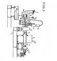
- Fig. 5 illustrates a rotary electric machine-manufacturing apparatus according to a second embodiment.
- This apparatus is essentially the same as in the first embodiment, apart from the rotator 2. Portions corresponding to the first embodiment are then denoted with the same reference numerals, and only different points are explained below.
- a continuously rotating device is employed as the rotator 2. Because a rotation activating mechanism is identical to that in the above description, Fig. 4 illustrates only a pulley at a driven side of the transmission mechanism 21, and illustrations of related mechanisms including a motor are omitted.
- a slip ring 8 is disposed halfway on the electric supply lines connecting the non-illustrated high-frequency power supply device with the wire-wound coils Sc of the work S.
- the slip ring 8 is employed so as to continuously supply and receive, by slidable movement at a relatively rotating portion, electric current between a stationary side and a rotating side.
- This slip ring 8 is located between the bearings 11 supporting the main shaft 20.
- This slip ring 8 includes a three-set ring for electrically exciting the three-phase type wire-wound coils Sc of the work S, and another ring for sending to the high-frequency power supply equipment, by a feed-back method, signals outputted by the thermistor 46 embedded in the wire-wound coils of the work S in such a manner that electric power to be supplied can be controlled.
- each process step in the varnish-infiltrating process is identical to the method according to the first embodiment, and a description thereof is omitted herein.
- the pulling amount of the electric supply lines 7 does not require an extra for a reverse rotation, and a cable bare, so that the pulling amount of the electric supply lines 7 can be minimized. Further, a structure of this apparatus becomes slightly complicated by a locating amount of the slip ring 8. However, when the varnish dropping-infiltrating process is implemented, an advantage can be secured, by always rotating the work S in a rotational direction, that the varnish can be applied to the work S further uniformly. Further, in contrast with a method of oscillating the work S according to the first embodiment, control of a reverse rotational position is not necessary. Therefore, controlling operations, of the high-frequency power supply device 4, and of a motor of the rotator 2 can be simplified. Other effects produced by the second embodiment are the same as effects produced in the first embodiment.
- a third embodiment features modified examples in connection with the reciprocating rotational angle of the rotator 2 according to the first embodiment, and with a structure to locate the dropping nozzles 61 for supplying a varnish 99.
- Figs. 6, 7 and 8 illustrate an example in which a reciprocatingly rotating device, which reciprocatingly rotates every 360 degrees, is employed as the rotator 2.
- Fig. 6 illustrates an example, in which the dropping nozzles 61 for dropping the varnish 99 downwards vertically are respectively allocated at one position every single target portion for application of varnish to the wire wound-coils, an arrangement which is identical to that of the first embodiment. That is, as illustrated in Fig. 6, the single dropping nozzle 61 is allocated to each outer peripheral surface 911 and 921 of each coil end 91 and 92 of the wire-wound coils Sc. Likewise, the single dropping nozzle 61 is allocated to each inner peripheral surface 912 and 922 of each coil end 91 and 92 of the wire-wound coils Sc.
- Fig. 7 illustrates an example, in which injector-type dropping nozzles 612 for spraying the varnish 99 are allocated at one position every single target portion for application of varnish to the wire wound-coils.
- each figure represents a view that essentially illustrates only the work S and the dropping nozzles.
- the dropping nozzles 612 can be allocated at appropriate positions, thereby enhancing freedom of the structure of the rotary electric machine-manufacturing apparatus.
- Fig. 8 illustrates an example, in which the varnish 99 is applied to the outer peripheral surfaces of the coil ends 91 and 92 by means of roll coating.
- a varnish-infiltrating device which includes a tray 616 in which the varnish 99 is accumulated, and a coater roll 615 for raising the varnish 99 accumulated in the tray 616.
- a width of the coater roll 615 it is accordingly possible to adjust accurately the area to which the varnish is applied, and thus enhance a degree in the application of varnish.
- Figs. 9 to 12 illustrates examples, in which a reciprocating rotation device is employed as the rotator 2, which reciprocatingly rotates every rotational angle within a rotational angle range of between 180 degrees or more and up to less than 360 degrees.
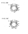
- Fig. 9 illustrates an example, in which the dropping nozzles 61 for dropping the varnish 99 downwards vertically are respectively allocated at two positions every single target portion for application of varnish to the wire wound-coils. That is, the two dropping nozzles 61 are allocated, at positions separated by about 180 degrees, each outer peripheral surface 911 of the coil end 91 and outer peripheral surface 921 of the coil end 92. Likewise, the two dropping nozzles 61 are allocated, at positions separated by about 180 degrees, each inner peripheral surface 912 of the coil end 91 and outer peripheral surface 922 of the coil end 92.In this case, as illustrated in Fig. 10, while the wire-wound coils Sc as the work S is reciprocatingly being rotated approximately every about 180 degrees, the dropping nozzles 61 drop the varnish 99.
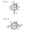
- Fig. 11 illustrates an example, in which injector-type dropping nozzles 612 are employed in combination with the normal dropping nozzles 61. More specifically, as is illustrated therein, in term of the nozzles for applying the varnish onto the outer peripheral surfaces 911 and 921 of the coil ends 91 and 92, the dropping nozzles 61, each of which faces a vertically top portion of the work S, are utilized in combination with the injector-type dropping nozzles 612, each of which faces a vertically bottom portion of the work S.
- the dropping nozzles 61 are utilized in combination with the injector-type dropping nozzles 612, each of which faces a vertically top portion of the work S.
- the varnish 99 vertically from the front relative to the outer peripheral surfaces 911 and 921 of the coil ends 91 and 92, or to the inner peripheral surfaces 912 and 922 thereof, thereby further enhancing a degree of precision in applying varnish.
- Fig. 12 illustrates an example, in which two nozzles, which make a pair, are all the injector-type dropping nozzles 612.
- the dropping nozzles 612 can be allocated at appropriate positions, thereby enhancing freedom of the structure of the rotary electric machine-manufacturing apparatus.
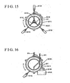
- FIGs. 13 through 16 illustrate an example in which a reciprocatingly rotating device is employed as the rotator 2, which reciprocatingly rotates every rotational angle within a rotational angle range of between 120 degrees or more and up to less than 180 degrees.
- Fig. 13 illustrates an example, in which a pair, which includes a combination of the single dropping nozzle 61 for dropping the varnish 99 downwards vertically and the two injector-type dropping nozzles 612, is utilized every single target portion for application of varnish to the wire wound-coils Sc.
- the singular dropping nozzle 61 and the two injector-type dropping nozzles 612 are allocated, at positions separated by about 120 degrees, every single target portion for application of varnish to the wire-wound coils Sc.
- the single dropping nozzle 61 is allocated at the vertically top portion of the work S, and the two injector-type dropping nozzles 612 are allocated respectively at positions separated at about 120 degrees from the vertically top portion.
- the singular dropping nozzle 61 is allocated at the vertically bottom portion of the work S, and the two injector-type dropping nozzles 612 are allocated respectively at positions separated at about 120 degrees from the vertically bottom portion. In this case, as illustrated in Fig.
- the dropping nozzle 61 drops the varnish 99 and the dropping nozzles 612 spray the varnish 99. That is, by rotating by rotating the wire-wound coils Sc at about 120 degrees in a first rotational direction (counter-clockwise direction) ((a) ⁇ (b)), and then rotating them at about 120 degrees in an opposite rotational direction (clockwise direction) ((b) ⁇ (c)), it is possible to supply the varnish 99 uniformly to the outer peripheral surfaces 912 and 921 and the inner peripheral surfaces 912 and 922, of the coil ends 91 and 92.
- Fig. 15 illustrates an example, in which a pair, which includes the three injector-type dropping nozzles 612, is utilized every single target portion for application of varnish to the wire wound-coils Sc.
- the dropping nozzles 612 can be allocated at appropriate positions, thereby enhancing freedom of the structure of the rotary electric machine-manufacturing apparatus.
- Fig. 16 illustrates an example, in which a pair, which includes a combination of the singular dropping nozzle 61 for dropping the varnish 99 downwards vertically, the singular injector-type dropping nozzle 612 and a singular coater roll 615 for roll-coating, is utilized every single target portion for application of varnish to the wire-wound coils Sc.
- the singular dropping nozzle 61, the singular injector-type dropping nozzle 612 and the singular coater roll 615 are allocated, at positions separated by about 120 degrees, every single target portion for application of varnish to the wire-wound coils Sc.
- each outer peripheral surface 911 and 921 of each coil end 91 and 92 the single dropping nozzle 61 is allocated at the vertically top portion of the work S, and the injector-type dropping nozzles 612 and the coater roll 615 are allocated respectively at positions separated at about 120 degrees from the vertically top portion.
- the singular dropping nozzle 61 is allocated at the vertically bottom portion of the work S, and the injector-type dropping nozzles 612 and the coater roll 615 are allocated respectively at positions separated at about 120 degrees from the vertically bottom portion.
- the present invention can be widely applied to manufacturing a stator, or a rotor, of a common multiple-phase rotary electric machine.
- the present invention can be applied to each process step in a process of infiltrating varnish into three-phase coils, of a three-phase induction motor or generator.
Landscapes
- Engineering & Computer Science (AREA)
- Power Engineering (AREA)
- Manufacturing & Machinery (AREA)
- Manufacture Of Motors, Generators (AREA)
Abstract
Description
Patent Document 1: JP07(1995)-031108A
Claims (22)
- A rotary electric machine-manufacturing apparatus utilized to implement a process of infiltrating varnish into wire-wound coils of a rotary electric machine, and of curing the varnish, the apparatus characterized in comprising:wherein electric supply lines connecting the power supply device with the wire-wound coils of the work are linked by a slip ring.a rotator supporting a work attached with the wire-wound coils and rotating the work;a power supply device supplying electric power to the wire-wound coils; anda varnish-infiltrating device supplying varnish to the wire-wound coils,
- The rotary electric machine-manufacturing apparatus according to claim 1, wherein the rotator is a continuously rotating device that rotates continuously in a rotational direction.
- A rotary electric machine-manufacturing apparatus utilized to implement a process of infiltrating varnish into wire-wound coils of a rotary electric machine, and of curing the varnish, the apparatus characterized in comprising:wherein the rotator is a reciprocatingly rotating device which reciprocatingly rotates in a first rotational direction and in an opposite rotational direction.a rotator supporting a work attached with the wire-wound coils and rotating the work;a power supply device supplying electric power to the wire-wound coils; anda varnish-infiltrating device supplying varnish to the wire-wound coils,
- The rotary electric machine-manufacturing apparatus according to claim 3, wherein electric supply lines from the power supply device are supported by an electric supply line twist-inhibiting mechanism.
- The rotary electric machine-manufacturing apparatus according to claim 3 or 4, wherein the reciprocatingly rotating device is structured so as to reciprocatingly repeat rotation at 360 degrees or more in a rotational direction.
- The rotary electric machine-manufacturing apparatus according to claim 3 or 4, wherein the reciprocatingly rotating device is structured so as to reciprocatingly repeat rotation at a rotational angle within a rotational angle range of between 180 degrees or more and up to less than 360 degrees in a rotational direction, and wherein the varnish-infiltrating device includes varnish-supplying means at least at two positions every single target portion for application of varnish to the wire-wound coils.
- The rotary electric machine-manufacturing apparatus according to claim 3 or 4, wherein the reciprocatingly rotating device is structured so as to reciprocatingly repeat rotation at a rotational angle within a rotational angle range of between 120 degrees or more and up to less than 180 degrees in a rotational direction, and wherein the varnish-infiltrating device includes varnish-supplying means at least at three positions every single target portion for application of varnish to the wire-wound coils.
- The rotary electric machine-manufacturing apparatus according to claim 6 or 7, wherein at least one of the varnish-supplying means is structured so as to discharge varnish by means of an injector.
- The rotary electric machine-manufacturing apparatus according to any one of claims 6, 7 and 8, wherein at least one of the varnish-supplying means is structured so as to supply the varnish by transferring and applying varnish raised by a coater roll.
- The rotary electric machine-manufacturing apparatus according to any one of claims 1 through 9, wherein the rotator is structured so as to support the work from a radially inner side thereof.
- The rotary electric machine-manufacturing apparatus according to any one of claims 1 through 10, wherein the power supply device is a high-frequency power supply device emanating electric power of which a frequency is higher than a level of a frequency of a commercial power source.
- The rotary electric machine-manufacturing apparatus according to any one of claims 1 through 11, wherein the work is a stator of a rotary electric machine.
- A method of manufacturing a rotary electric machine, the method including a process infiltrating a varnish into wire-wound coils of a rotary electric machine, and of curing the varnish characterized in comprising the steps of:supporting a work attached with wire-wound coils;continuously rotating the work in a rotational direction;supplying electric power to the wire-wound coils while the work is being continuously rotated; andsupplying varnish to the wire-wound coils while electric power is being supplied to the wire-wound coils.
- A method of manufacturing a rotary electric machine, the method including a process infiltrating a varnish into wire-wound coils of a rotary electric machine, and of curing the varnish characterized in comprising the steps of:supporting a work attached with wire-wound coils;rotating the work reciprocatingly in a first rotational direction and in an opposite rotational direction;supplying electric power to the wire-wound coils while the work is being rotated reciprocatingly in the first rotational direction and in the opposite rotational direction; andsupplying varnish to the wire-wound coils while electric power is being supplied to the wire-wound coils.
- The method of manufacturing a rotary electric machine according to claim 14, wherein the reciprocating rotation is performed by reciprocatingly repeating rotation at 360 degrees or more in a rotational direction.
- The method of manufacturing a rotary electric machine according to claim 14, wherein the reciprocating rotation is performed by reciprocatingly repeating rotation at a rotational angle within a rotational angle range of between 180 degrees or more and up to less than 360 degrees in a rotational direction, and wherein the supply of the varnish to the wire-wound coils is performed simultaneously by varnish-supplying means installed at least at two positions every single target portion for application of varnish to the wire-wound coils.
- The method of manufacturing a rotary electric machine according to claim 14, wherein the reciprocating rotation is performed by reciprocatingly repeating rotation at a rotational angle within a rotational angle range of between 120 degrees or more and up to less than 180 degrees in a rotational direction, and wherein the supply of the varnish to the wire-wound coils is performed simultaneously by varnish-supplying means installed at least at three positions every single target portion for application of varnish to the wire-wound coils.
- The method of manufacturing a rotary electric machine according to claim 16 or 17,
wherein at least one of the varnish-supplying means is structured so as to discharge varnish by means of an injector. - The method of manufacturing a rotary electric machine according to any one of claims 16, 17 and 18, wherein at least one of the varnish-supplying means is structured so as to supply the varnish by transferring and applying varnish raised by a coater roll.
- The method of manufacturing a rotary electric machine according to any one of claims 13 through 19, wherein the rotation of the work is performed in a condition where the work is being supported from a radially inner side thereof.
- The method of manufacturing a rotary electric machine according to any one of claims 13 through 20, wherein the electric power supplied to the wire-wound coils is electric power of which a frequency is higher than a level of a frequency of a commercial power source.
- The method of manufacturing a rotary electric machine according to any one of claims 13 through 21, wherein the work is a stator of a rotary electric machine.
Applications Claiming Priority (3)
| Application Number | Priority Date | Filing Date | Title |
|---|---|---|---|
| JP2003318948 | 2003-09-10 | ||
| JP2003318948 | 2003-09-10 | ||
| PCT/JP2004/013235 WO2005027320A1 (en) | 2003-09-10 | 2004-09-10 | Device and method for manufacture of rotating electric machine |
Publications (2)
| Publication Number | Publication Date |
|---|---|
| EP1610445A1 true EP1610445A1 (en) | 2005-12-28 |
| EP1610445A4 EP1610445A4 (en) | 2006-01-04 |
Family
ID=34308543
Family Applications (1)
| Application Number | Title | Priority Date | Filing Date |
|---|---|---|---|
| EP04787875A Withdrawn EP1610445A4 (en) | 2003-09-10 | 2004-09-10 | Device and method for manufacture of rotating electric machine |
Country Status (6)
| Country | Link |
|---|---|
| US (1) | US8215260B2 (en) |
| EP (1) | EP1610445A4 (en) |
| JP (1) | JP4691448B2 (en) |
| KR (1) | KR100961029B1 (en) |
| CN (1) | CN1748351B (en) |
| WO (1) | WO2005027320A1 (en) |
Cited By (5)
| Publication number | Priority date | Publication date | Assignee | Title |
|---|---|---|---|---|
| WO2009042021A1 (en) * | 2007-09-25 | 2009-04-02 | Siemens Energy, Inc. | Method for spacing electrical conductors and related devices |
| WO2018055004A1 (en) * | 2016-09-23 | 2018-03-29 | Aktiebolaget Skf | Dielectric heating of motor insulation with rf energy stimulus to repair defects and degradation in the insulating material in-situ |
| EP4456391A1 (en) * | 2023-04-25 | 2024-10-30 | Siemens Aktiengesellschaft | Method for impregnating and impregnating device |
| EP4456384A1 (en) * | 2023-04-25 | 2024-10-30 | Siemens Aktiengesellschaft | Digital twin system |
| EP4456392A1 (en) * | 2023-04-25 | 2024-10-30 | Siemens Aktiengesellschaft | Method for impregnating and impregnating device |
Families Citing this family (12)
| Publication number | Priority date | Publication date | Assignee | Title |
|---|---|---|---|---|
| CN101233396B (en) * | 2005-03-23 | 2010-12-22 | 丰田自动车株式会社 | Temperature detector and fixing material transmission suppressing structure |
| CN101783554B (en) * | 2009-12-14 | 2015-04-22 | 南车株洲电力机车有限公司 | Rolling type rotate baking method and device of high-rating generator |
| JP6018847B2 (en) * | 2012-09-07 | 2016-11-02 | 株式会社日立産機システム | Heat treatment apparatus and heat treatment method for rotating electrical machine coil |
| EP2996228B1 (en) * | 2013-07-12 | 2017-10-11 | Aisin Aw Co., Ltd. | Varnish impregnation device and varnish impregnation method |
| CN106191382B (en) * | 2014-10-16 | 2018-07-06 | Posco公司 | Has the annealing device of a pair of linear stove and collector ring |
| JP2016213928A (en) * | 2015-04-30 | 2016-12-15 | ファナック株式会社 | Stator having varnish feed passage and motor |
| JP6458708B2 (en) * | 2015-11-04 | 2019-01-30 | トヨタ自動車株式会社 | Manufacturing method of motor stator |
| US11707760B2 (en) * | 2017-12-22 | 2023-07-25 | Tecnofirma S.P.A. | Impregnation plant and method for components of electric motors |
| JP7465648B2 (en) * | 2019-10-25 | 2024-04-11 | 東芝産業機器システム株式会社 | Adhesive application device, adhesive application method, and rotor manufacturing method |
| CN115088166B (en) * | 2020-03-25 | 2026-05-12 | 日立安斯泰莫株式会社 | Method for manufacturing stator of rotating electrical machine, and rotating electrical machine |
| CN114257052B (en) * | 2020-09-23 | 2023-09-15 | 丰田自动车株式会社 | Manufacturing method and manufacturing device of rotor for rotating electrical machine |
| US12573925B2 (en) * | 2022-10-19 | 2026-03-10 | Ford Global Technologies, Llc | Assembly for varnish injection of a vehicle motor |
Family Cites Families (18)
| Publication number | Priority date | Publication date | Assignee | Title |
|---|---|---|---|---|
| US2200794A (en) * | 1937-05-08 | 1940-05-14 | Bell Telephone Labor Inc | Electrical connector |
| GB1241416A (en) | 1967-08-02 | 1971-08-04 | Newage Lyon Ltd | Improvements relating to the manufacture of wound electrical rotors |
| US3953275A (en) * | 1975-01-30 | 1976-04-27 | Emerson Electric Co. | Method and apparatus for liquid adhesive application |
| US4559698A (en) * | 1983-12-21 | 1985-12-24 | General Electric Company | Method of treating a loose wound core, method of fabricating a loose wound core, and method of operating apparatus |
| IT1200443B (en) * | 1985-04-02 | 1989-01-18 | Axis Spa | Electric motor stator winding forming machine |
| US4969414A (en) * | 1985-06-10 | 1990-11-13 | General Electric Company | Apparatus for treating cores |
| US5094960A (en) | 1988-10-07 | 1992-03-10 | New York Blood Center, Inc. | Removal of process chemicals from labile biological mixtures by hydrophobic interaction chromatography |
| CN2051008U (en) * | 1989-07-18 | 1990-01-10 | 哈尔滨绝缘材料厂 | Insulating paint-cloth |
| JPH05115160A (en) | 1991-07-16 | 1993-05-07 | Toshiba Chem Corp | Method of impregnating stator coil with insulating varnish |
| JPH06327203A (en) * | 1993-05-17 | 1994-11-25 | Toshiba Corp | Method for impregnating varnish of electrical equipment |
| JPH0731108A (en) | 1993-07-09 | 1995-01-31 | Toshiba Corp | Method for impregnating varnish of electrical equipment |
| KR200253278Y1 (en) | 1996-08-31 | 2001-12-28 | 구자홍 | Varnish coating device |
| US5990450A (en) * | 1996-11-08 | 1999-11-23 | Odawara Automation, Inc. | Rotary conveyor |
| JP3405653B2 (en) * | 1997-04-03 | 2003-05-12 | 三菱電機株式会社 | Hermetic electric compressor, method for producing the same, and refrigeration / air-conditioning apparatus using the same |
| JPH10290573A (en) | 1997-04-14 | 1998-10-27 | Hitachi Ltd | Current control device |
| DE19729778A1 (en) | 1997-07-11 | 1999-01-21 | Blutspendedienst Der Drk Lande | Process for the preparation of virus-inactivated biological fluids |
| US5919907A (en) | 1997-12-22 | 1999-07-06 | Shanbrom Technologies Llc | Preparation and utilization of a novel sterile albumin |
| DE10111660B4 (en) | 2001-03-09 | 2021-09-02 | Maschinenbau Gottlob Thumm Gmbh | Method and device for coating components provided with windings |
-
2004
- 2004-09-10 JP JP2005513918A patent/JP4691448B2/en not_active Expired - Fee Related
- 2004-09-10 KR KR1020057013790A patent/KR100961029B1/en not_active Expired - Fee Related
- 2004-09-10 EP EP04787875A patent/EP1610445A4/en not_active Withdrawn
- 2004-09-10 US US10/543,833 patent/US8215260B2/en not_active Expired - Fee Related
- 2004-09-10 CN CN2004800038164A patent/CN1748351B/en not_active Expired - Fee Related
- 2004-09-10 WO PCT/JP2004/013235 patent/WO2005027320A1/en not_active Ceased
Cited By (9)
| Publication number | Priority date | Publication date | Assignee | Title |
|---|---|---|---|---|
| WO2009042021A1 (en) * | 2007-09-25 | 2009-04-02 | Siemens Energy, Inc. | Method for spacing electrical conductors and related devices |
| US8641855B2 (en) | 2007-09-25 | 2014-02-04 | Siemens Energy, Inc. | Method for spacing electrical conductors and related devices |
| WO2018055004A1 (en) * | 2016-09-23 | 2018-03-29 | Aktiebolaget Skf | Dielectric heating of motor insulation with rf energy stimulus to repair defects and degradation in the insulating material in-situ |
| EP4456391A1 (en) * | 2023-04-25 | 2024-10-30 | Siemens Aktiengesellschaft | Method for impregnating and impregnating device |
| EP4456384A1 (en) * | 2023-04-25 | 2024-10-30 | Siemens Aktiengesellschaft | Digital twin system |
| EP4456392A1 (en) * | 2023-04-25 | 2024-10-30 | Siemens Aktiengesellschaft | Method for impregnating and impregnating device |
| WO2024223132A1 (en) * | 2023-04-25 | 2024-10-31 | Innomotics Gmbh | Method for impregnating and impregnating device |
| WO2024223131A1 (en) * | 2023-04-25 | 2024-10-31 | Innomotics Gmbh | Impregnation method, and an impregnation device |
| WO2024223094A1 (en) * | 2023-04-25 | 2024-10-31 | Innomotics Gmbh | Digital twin system |
Also Published As
| Publication number | Publication date |
|---|---|
| JPWO2005027320A1 (en) | 2006-11-24 |
| EP1610445A4 (en) | 2006-01-04 |
| US8215260B2 (en) | 2012-07-10 |
| WO2005027320A1 (en) | 2005-03-24 |
| JP4691448B2 (en) | 2011-06-01 |
| KR20060061928A (en) | 2006-06-08 |
| US20060165879A1 (en) | 2006-07-27 |
| KR100961029B1 (en) | 2010-06-01 |
| CN1748351A (en) | 2006-03-15 |
| CN1748351B (en) | 2010-11-03 |
Similar Documents
| Publication | Publication Date | Title |
|---|---|---|
| US8215260B2 (en) | Rotary electric machine-manufacturing apparatus and method of manufacturing the same | |
| JP4818940B2 (en) | Stator coil heating device | |
| CN105359394B (en) | Stator heating device and stator heating method | |
| WO2021035936A1 (en) | Electric heating and rotating immersion paint device for motor winding and immersion paint process thereof | |
| JP6137314B2 (en) | Varnish impregnation apparatus and varnish impregnation method | |
| EP2448090B1 (en) | Stator of vehicle ac generator and method for manufacturing the same | |
| EP2110932A1 (en) | Method and device for heating stator | |
| US20040084443A1 (en) | Method and apparatus for induction heating of a wound core | |
| CN1060878C (en) | Electrically insulated coils and a method of manufacturing thereof | |
| JP2005110493A (en) | Heat treatment method and apparatus for rotating electrical machine coil | |
| JP5868913B2 (en) | Stator work heating device, stator work heating method, and stator coil manufacturing method | |
| JP2011062036A (en) | Varnish treatment method | |
| JP4356406B2 (en) | Heating apparatus for rotating electrical machine coil | |
| JP2005102404A (en) | Varnish impregnation equipment | |
| JP2015126645A (en) | Heating method of stator of electric machine and heating device | |
| JP6243633B2 (en) | Varnish processing equipment | |
| US20130097852A1 (en) | Method of manufacturing stator of rotating electrical machine | |
| JP4735370B2 (en) | Varnish impregnation method | |
| JP5734110B2 (en) | Method for impregnating varnish of winding body for rotating electrical machine and winding body for rotating electrical machine manufactured by the method | |
| JP5579204B2 (en) | Coil varnish impregnation method and coil | |
| JP2008092733A (en) | Heating method for rotating electrical machine winding and processing apparatus for performing this heating method | |
| US20250175064A1 (en) | Method for impregnating a stator for a dynamoelectric machine | |
| JP2000311780A (en) | Heating method | |
| JP2023111744A (en) | Coil manufacturing method and coil manufacturing apparatus | |
| Osipov et al. | The Improving Reliability of the Electric Drive and the Productivity of the Technological Process are Due to More Complete Use of the Thermal Resource of the Electric Motor |
Legal Events
| Date | Code | Title | Description |
|---|---|---|---|
| PUAI | Public reference made under article 153(3) epc to a published international application that has entered the european phase |
Free format text: ORIGINAL CODE: 0009012 |
|
| 17P | Request for examination filed |
Effective date: 20050810 |
|
| AK | Designated contracting states |
Kind code of ref document: A1 Designated state(s): AT BE BG CH CY CZ DE DK EE ES FI FR GB GR HU IE IT LI LU MC NL PL PT RO SE SI SK TR |
|
| AX | Request for extension of the european patent |
Extension state: AL HR LT LV MK |
|
| A4 | Supplementary search report drawn up and despatched |
Effective date: 20051118 |
|
| DAX | Request for extension of the european patent (deleted) | ||
| RBV | Designated contracting states (corrected) |
Designated state(s): DE FR GB |
|
| 17Q | First examination report despatched |
Effective date: 20150327 |
|
| STAA | Information on the status of an ep patent application or granted ep patent |
Free format text: STATUS: THE APPLICATION IS DEEMED TO BE WITHDRAWN |
|
| 18D | Application deemed to be withdrawn |
Effective date: 20150807 |