EP1610416A2 - Appareil électrique adapté à coopérer avec un peigne de répartition horizontale - Google Patents
Appareil électrique adapté à coopérer avec un peigne de répartition horizontale Download PDFInfo
- Publication number
- EP1610416A2 EP1610416A2 EP05291312A EP05291312A EP1610416A2 EP 1610416 A2 EP1610416 A2 EP 1610416A2 EP 05291312 A EP05291312 A EP 05291312A EP 05291312 A EP05291312 A EP 05291312A EP 1610416 A2 EP1610416 A2 EP 1610416A2
- Authority
- EP
- European Patent Office
- Prior art keywords
- orifice
- recess
- face
- lateral surface
- lateral
- Prior art date
- Legal status (The legal status is an assumption and is not a legal conclusion. Google has not performed a legal analysis and makes no representation as to the accuracy of the status listed.)
- Granted
Links
- 210000001520 comb Anatomy 0.000 description 11
- 230000037431 insertion Effects 0.000 description 9
- 238000003780 insertion Methods 0.000 description 9
- 238000000605 extraction Methods 0.000 description 5
- 230000005611 electricity Effects 0.000 description 3
- 239000007769 metal material Substances 0.000 description 3
- 239000004020 conductor Substances 0.000 description 2
- 230000007935 neutral effect Effects 0.000 description 2
- RYGMFSIKBFXOCR-UHFFFAOYSA-N Copper Chemical compound [Cu] RYGMFSIKBFXOCR-UHFFFAOYSA-N 0.000 description 1
- 101100536354 Drosophila melanogaster tant gene Proteins 0.000 description 1
- 229910000639 Spring steel Inorganic materials 0.000 description 1
- 240000008042 Zea mays Species 0.000 description 1
- 229910052802 copper Inorganic materials 0.000 description 1
- 239000010949 copper Substances 0.000 description 1
- 235000021183 entrée Nutrition 0.000 description 1
- 238000009434 installation Methods 0.000 description 1
- 239000011810 insulating material Substances 0.000 description 1
- 238000002955 isolation Methods 0.000 description 1
- 238000004519 manufacturing process Methods 0.000 description 1
- 210000002445 nipple Anatomy 0.000 description 1
- 238000005192 partition Methods 0.000 description 1
- 230000035515 penetration Effects 0.000 description 1
- 210000001364 upper extremity Anatomy 0.000 description 1
Images


Classifications
-
- H—ELECTRICITY
- H01—ELECTRIC ELEMENTS
- H01H—ELECTRIC SWITCHES; RELAYS; SELECTORS; EMERGENCY PROTECTIVE DEVICES
- H01H71/00—Details of the protective switches or relays covered by groups H01H73/00 - H01H83/00
- H01H71/08—Terminals; Connections
- H01H71/082—Connections between juxtaposed circuit breakers
-
- H—ELECTRICITY
- H01—ELECTRIC ELEMENTS
- H01R—ELECTRICALLY-CONDUCTIVE CONNECTIONS; STRUCTURAL ASSOCIATIONS OF A PLURALITY OF MUTUALLY-INSULATED ELECTRICAL CONNECTING ELEMENTS; COUPLING DEVICES; CURRENT COLLECTORS
- H01R9/00—Structural associations of a plurality of mutually-insulated electrical connecting elements, e.g. terminal strips or terminal blocks; Terminals or binding posts mounted upon a base or in a case; Bases therefor
- H01R9/22—Bases, e.g. strip, block, panel
- H01R9/24—Terminal blocks
- H01R9/26—Clip-on terminal blocks for side-by-side rail- or strip-mounting
- H01R9/2675—Electrical interconnections between two blocks, e.g. by means of busbars
-
- H—ELECTRICITY
- H01—ELECTRIC ELEMENTS
- H01R—ELECTRICALLY-CONDUCTIVE CONNECTIONS; STRUCTURAL ASSOCIATIONS OF A PLURALITY OF MUTUALLY-INSULATED ELECTRICAL CONNECTING ELEMENTS; COUPLING DEVICES; CURRENT COLLECTORS
- H01R13/00—Details of coupling devices of the kinds covered by groups H01R12/70 or H01R24/00 - H01R33/00
- H01R13/62—Means for facilitating engagement or disengagement of coupling parts or for holding them in engagement
- H01R13/629—Additional means for facilitating engagement or disengagement of coupling parts, e.g. aligning or guiding means, levers, gas pressure electrical locking indicators, manufacturing tolerances
- H01R13/633—Additional means for facilitating engagement or disengagement of coupling parts, e.g. aligning or guiding means, levers, gas pressure electrical locking indicators, manufacturing tolerances for disengagement only
Definitions
- the invention relates to electrical apparatus adapted to cooperate with a horizontal distribution comb.
- such device which is of the modular type, that is to say to form globally parallelepiped with two main faces and lateral faces extending from one to the other of the main faces, in this case a rear face, a face lower, a front face and an upper face, which has terminals for a comb with teeth regularly distributed according to a step corresponding to a width (distance between the two main faces) normalized for this type of device, for example the width known as the "module", which is of the order of 18 mm.
- the invention is aimed at such a device offering a simple cooperation and convenient with the horizontal distribution combs.
- an electrical device comprising a face having at least one orifice giving access to a terminal adapted to receive a tooth of a horizontal distribution comb arranged to be arranged opposite said apparatus in a left-right direction, characterized in that said face has a recess, located away from said orifice in said direction left-right, adapted to receive a tool for extracting said comb, said recess being defined at least by a bottom surface and a surface lateral, said bottom surface being recessed with respect to a base surface which defines the general plane according to which said face is oriented, said surface lateral portion being located between said bottom surface and said base surface.
- the recess allows to exercise this effort in good conditions with a tool as common as a flat blade screwdriver placed first in the recess facing a portion of the comb between two teeth consecutive and then flipping this tool to separate the comb from the device.
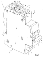
- the modular circuit breaker 1 illustrated in FIG. 1 has a shape globally parallelepipedic.
- main faces 2 and side faces extending from one to the other of the main faces 2, namely a rear face 3, a face lower 4, a front face 5 and an upper face 6.
- the rear face 3 has a notch 7 for mounting the circuit breaker 1 on a standard rail with an ⁇ profile such as the rail 30 illustrated in FIG. 3.
- the lower face 4 has two access ports to screw terminals (not visible on the drawings).
- the front face 5 has, in central position, about half of its length, a nose 8 having an operating lever 9. Under the nose 8 itself find two orifices 10 and 11 each allowing access to the head of the screw of one of the terminals for which an access orifice is formed in the face lower 4.
- the upper face 6 has two orifices 12 and 13 giving each access to one of the two insertion terminals 14 (FIG. 2) that the circuit breaker comprises 1.
- Each terminal 14 comprises a clamp 15, a spring 16 and a pad of mounting and connection 17.
- the clip 15 is made of metallic material which is a good conductor of electricity, here in tinned copper. She is in the general shape of a lyre. It has two sections 20A and 20B each being connected at one end to one end respective of an intermediate section 20C generally rectilinear. The sections 20A and 20B are symmetrical, i.e., one is the mirror image of the other.
- the sections 20A and 20B are approaching one on the other side to an inflection zone 21 where they are closest to each other. Between the inflection zone 21 and the intermediate section 20C, the sections 20A and 20B deviate from each other, each section having in this part a conformation which is here relatively rectilinear.
- the spring 16 is made of metallic material having good elasticity, here in spring steel. It has a general shape in C. It surrounds closely the portion of the clamp 15 comprising the intermediate section 20C and the portion of each of the sections 20A and 20B situated between the section 20C and the inflection zone 21, the ends of the spring 16 each bearing against the outer face of one of the section 20A and 20B at the inflection zone 21.
- the block 17 is here made in one piece with the clamp 15, to which it is connected by the edge of the intermediate section 20C located at the rear in the figure 2, at the level of a setback in slight overhang identical to that seen at the front in Figure 2.
- the pavement 17 is flat and extends on a plane parallel to that according to which are generally oriented the clamp 15 and the spring 16.
- the block 17 is arranged by relative to the intermediate section 20C, on the opposite side to the one where the sections 20A and 20B, that is to say that it is arranged on the side seen below.
- the block 17 makes it possible to operate the mechanical fixing of the terminal 14 in circuit breaker 1 and the electrical connection of terminal 14 to the internal circuit at circuit breaker 1.
- Each terminal 14 is disposed in the circuit breaker 1 parallel to the main faces 2 with the distal ends of sections 20A and 20B located at near the face 6, the space between the sections 20A and 20B being aligned with the orifice 12 or with the orifice 13.
- Each of the terminals 14 constitutes an entrance terminal for one of the poles of an alternating current source, here a neutral pole and a phase pole.
- the power supply of the circuit breaker 1 is intended to be carried out by two unipolar horizontal distribution combs conventional, worn respectively at the neutral potential and the phase potential, such as combs 25A and 25B shown in FIGS.
- the Combs 25A and 25B are here identical. They each have a sill 26 in continuous strip form from which project a plurality of teeth 27, here thirteen in number.
- the sill 26 and the teeth 27 are made in one piece in a metal material good conductor of electricity.
- the sill 26 and the teeth 27 are here oriented in the same plane.
- the teeth 27 are regularly distributed, following a step (center distance between two consecutive teeth) corresponding to the width of a circuit breaker 1, that is to say the standardized distance between its lateral faces 2 known as "Module", which is of the order of 18 mm.
- the combs 25A and 25B each comprise, in addition to the sill 26 and teeth 27, a casing 28 of U-shaped insulating material which covers the stalk 26 from its slice to the root of the teeth 27.
- the edge of the sill 26 is rectilinear and located at the same level as the edge of the envelope 28 (see FIG. cut from the envelope 28).
- Each terminal 14 is provided to receive a tooth such as 27, for simple insertion into the clip 15, with of course the insertion which is done on the side of the distal end of the sections 20A and 20B and the comb of which the tooth is part which is oriented transversely to the terminal, that is to say in one direction left right.
- the conformation of the terminal 14 and the tooth 27 are such that after insertion the tooth is strongly gripped by the clip 15 at the level of the zones of inflection 21, so that a good electrical contact is established.
- the orifices 12 and 13 formed in the upper face 6 of the circuit breaker 1 each allow a tooth 27 to access the insertion terminal 14 located just below.
- the orifices 12 and 13 are offset in the direction of the width of the breaker 1, the orifice 12 being here on the left side and the orifice 13 on the right side. They are also offset in the direction of the depth, the orifice 12 being located in rear of the orifice 13.
- the teeth of a same comb for example the comb 25A
- the teeth of another comb for example the comb 25B
- the set of devices mounted on the rail 30 comprises, as a group head apparatus, a switch differential 31 and a set of twelve circuit breakers 1 of which only the two most close to the switch 31 have been illustrated, so as not to overload the drawing.
- the differential switch 31 is of the type described in the French patent 2751 162.
- Its upper face 32 has two orifices 33 and 34 for access to input screw terminals and two orifices 35 and 36 for access to output terminals.
- the input terminals and the output terminals of the switch 31 are screw terminals.
- the front face of the switch 31 has orifices 37 to 40 each allowing access to the clamping screw of one of the input terminals or Release.
- the arrangement of the orifices 33 and 34 with respect to the rear face and to the left main face of the switch 31 is identical to that of the orifices 12 and 13 relative to the corresponding faces of the circuit-breaker 1, and likewise for the orifices 35 and 36 but vis-à-vis the right main face.
- the left extreme tooth 27 of the comb 25A can be inserted in the hole 35 and the other teeth 27 of this comb in the orifices 12 of the 1 breakers while the extreme left tooth of comb 25B can be introduced into the orifice 36 and the other teeth of this comb in the orifices 13 of the circuit breakers 1.
- the clamping of the output terminal corresponding to the orifice 35 is effected thanks to a screwdriver inserted into the hole 39 and tightening the terminal corresponding to the orifice 36 is made through a screwdriver engaged in the orifice 40.
- the partition 41 which projects on the upper face 32 of the switch 31 serves, as explained in French Patent 2,751,162, to avoid having inadvertently one comb at a time in an output terminal (port 35 or 36) and in an input terminal (hole 33 or 34), which would short-circuit the switch 31.
- the input terminals of the switch 31 are supplied by means of cables (not shown) connected to a connection point to the network of distribution of electricity.
- the upper face 6 has a base surface 45 which defines the plane in which is oriented the face 6.
- the surface 45 is here flat.
- Each of the orifices 12 and 13 in the form of an outline slot rectangular in the extension of which there are surfaces 46 serving driving abutment for a comb such as 25A and 25B, the surfaces 46 being arranged at the same level, located slightly below the base area 45.
- the face 6 has a bowl 47 delimited by a bottom surface 48, a front side surface 49, a side surface left 50, by a rear lateral surface 51 and by a right lateral surface 52.
- the bottom surface 48 is rectangular and oriented parallel to the base area 45, the distance between surfaces 45 and 48, the depth of the cup 47 being here of the order of 1.5 mm.
- the front side surface 49 is tilted back and toward the surface 48 whereas the lateral surfaces 50, 51 and 52 are straight.
- the gap between left lateral surface 50 and the right lateral surface 52, the width of the bowl 47, is of the order of 6.5 mm.
- the top of the front lateral surface 49 is disposed at the level of the front end of the face 6.
- the rear lateral surface 51 is disposed behind the orifice 13 and in before the orifice 12.
- the face 6 has a tooth 53 in protruding from the base surface 45.
- the face 6 presents a bowl 55 having a bottom surface 56, a front side wall 57, a left side surface 58, a rear side surface 59 and a side surface right 60.
- the bottom surface 56 of the bowl 55 is rectangular and oriented parallel to the base surface 45, the distance between the surfaces 45 and 56, the depth of the bowl 55 being the same as the distance between surfaces 45 and 48.
- the front lateral surface 57 of the bowl 55 is inclined towards the rear and towards the bottom surface 56 while the side surfaces 58, 59 and 60 are straight.
- the gap between the left lateral surface 58 and the right lateral surface 60, the width of the bowl 55, is the same as that of the bowl 47.
- the bottom surface 56 has a length (extension in the fore-and-aft direction) much smaller than that of the bottom surface 48 of the bowl 47.
- the dimensions of the bowls 47 and 55, and in particular their width and their depth, are intended to enable them to cooperate with a screwdriver to flat blade such as the screwdriver 65 shown in Figures 4 and 5, including the blade has a width of 5.5 mm.
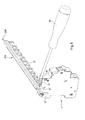
- the screwdriver 65 is then tilted around of the front end of the bowl 47, and more precisely around the edge 66 situated at the junction between the base surface 45 and the front lateral surface 49, in the direction where the flat blade deviates from the face 6, that is to say in the sense that the operator lowers the handle of the screwdriver 65, the teeth 27 of the comb 25B being thus extracted from the various terminals that comprise the devices with which cooperates this comb, as shown in Figure 5.
- the tooth 53 disposed projecting between the bowl 47 and the orifice 12 allows to avoid the blade of the screwdriver 65, during the tilting maneuver for extract the comb 25B, slide backwards and abut against the comb 25A.
- the orifice such as 12, located behind is positioned on the right side rather than the left side and the orifice such as 13, located front, on the left rather than on the right side, with of course the bowl than 47 which is then located to the right of the orifice such as 13 and in front of the orifice such than 12 while the bowl such as 55 is located behind the orifice such as 13 and to the left of the orifice such as 12.
- the face 6 of the apparatus 1 has a single orifice such as 12 and 13 or more than two orifices.
- the bowl such as 47 or 55 is replaced by a bowl shaped differently, or even by another type of recess bounded by a bottom surface such as 48 or 56 and by a single left or right side surface such as 50, 52, 58 or 60.
- the abutment surfaces 46 are shaped differently, they are for example formed directly by a portion of the base surface 45, or no stop surface is provided, the stop of the sinking of teeth such as 27 being operated directly by the terminal such as 14.
- tooth 53 is removed or is then replaced by another type of protuberance, for example a nipple;
- the face such as 6 belongs to a modular device other than a simple circuit breaker, for example a fused circuit breaker or a differential circuit breaker constituting a group head apparatus whose upper face is similar to that of the switch 31 but with the right half which is shaped like the face 6, or else the face such as 6 belongs to a device that is not of type modular;
- the terminal to which gives access the orifice such as 12 or 13 is a terminal insertion of another type, for example such as those illustrated on the patent 0 434 964 or else it is a question of terminals of a different type, for screw;
- the output terminals of devices such as 1 are replaced by terminals of another type, for example automatic terminals or connection terminals fast, and likewise for the differential switch 31 or for another group head unit; and / or the combs used are replaced by combs of another type, for example a comb whose sill is not co
Landscapes
- Distribution Board (AREA)
- Coupling Device And Connection With Printed Circuit (AREA)
- Connection Or Junction Boxes (AREA)
- Escalators And Moving Walkways (AREA)
- Automatic Cycles, And Cycles In General (AREA)
- Breakers (AREA)
Abstract
Description
- ladite face présente une surface de butée d'enfoncement pour une portion dudit peigne autre que ladite dent, ladite surface de fond étant en retrait par rapport à ladite surface de butée tandis que ladite surface latérale présente au moins une portion située entre ladite surface de fond et ladite surface de butée ; et optionnellement
- ladite surface de butée est en léger retrait par rapport à ladite surface de base ; et/ou
- ladite face présente à l'avant dudit renfoncement une arête d'appui de basculement pour ledit outil ; et optionnellement
- ladite arrête est située à la jonction entre une surface latérale avant délimitant ledit renfoncement et ladite surface de base ; et optionnellement
- ladite surface latérale avant s'étend de ladite surface de base à ladite surface de fond ; et/ou
- ledit renfoncement est également délimité par une surface latérale avant s'étendant de ladite surface de base à ladite surface de fond, ladite surface latérale avant étant inclinée vers l'arrière et vers la surface de fond ; et/ou
- ladite face présente à l'arrière dudit renfoncement une surface d'arrêt pour interdire la progression dudit outil dans ledit renfoncement vers l'arrière au-delà de ladite surface d'arrêt ; et optionnellement
- ladite surface d'arrêt est située en arrière dudit orifice à l'écart duquel est situé ledit renfoncement suivant la direction gauche - droite ; et/ou
- ladite surface d'arrêt est formée par une surface latérale arrière dudit renfoncement ; et/ou
- ledit renfoncement est également délimité par une surface latérale arrière situé entre ladite surface de fond et ladite surface de base ; et optionnellement
- ladite surface latérale arrière est droite ; et/ou
- ledit renfoncement est une cuvette, délimitée tant par ladite surface de fond et par ladite surface latérale, dite première surface latérale, que par une deuxième surface latérale opposée à la première surface latérale, par une troisième surface latérale disposée à l'arrière entre la première surface latérale et la deuxième surface latérale et par une quatrième surface latérale disposée à l'avant entre la première surface latérale et la deuxième surface latérale ; et optionnellement
- ladite surface de fond est plate, ladite première surface latérale, ladite deuxième surface latérale et ladite troisième surface latérale sont droites tandis que ladite quatrième surface latérale est inclinée vers la surface de fond et vers l'arrière ; et/ou
- ladite surface de fond est rectangulaire et allongée suivant la direction avant - arrière ; et/ou
- ledit renfoncement est adapté à recevoir l'extrémité d'une lame plate de tournevis ayant une largeur de 5,5 mm ; et/ou
- ledit orifice présente la forme d'une fente à contour rectangulaire ; et optionnellement
- ledit orifice est orienté suivant ladite direction gauche - droite tandis que ladite face présente dans le prolongement dudit orifice une surface de butée d'enfoncement pour une portion dudit peigne autre que ladite dent, ladite surface de fond étant située en retrait par rapport à ladite surface de butée tandis que ladite surface latérale présente au moins une portion située entre ladite surface de fond et ladite surface de butée ; et/ou
- ladite face présente :
- deux dits orifices, respectivement un premier orifice et un deuxième orifice situé en arrière et à gauche du premier orifice ; et
- deux dits renfoncements, respectivement un premier renfoncement et un deuxième renfoncement, le premier renfoncement étant disposé à gauche du premier orifice et en avant du deuxième orifice, le deuxième renfoncement étant disposé en arrière du premier orifice et à droite du deuxième orifice ; et alternativement
- ladite face présente :
- deux dits orifices, respectivement un premier orifice et un deuxième orifice situés en arrière et à droite du premier orifice ; et
- deux dits renfoncements, respectivement un premier renfoncement et un deuxième renfoncement, le premier renfoncement étant disposé à droite du premier orifice et en avant du deuxième orifice, le deuxième renfoncement étant disposé en arrière du premier orifice et à gauche du deuxième orifice ; et optionnellement
- ladite face présente une protubérance entre ledit premier renfoncement et ledit deuxième orifice ; et/ou
- ladite face est la face supérieure dudit appareil.
- la figure 1 est une vue en perspective d'un disjoncteur modulaire conforme à l'invention ;
- la figure 2 est une vue en perspective d'une des bornes à insertion que comporte ce disjoncteur ;
- la figure 3 est une vue en perspective d'un ensemble formé par un interrupteur différentiel modulaire, par plusieurs disjoncteurs tels que celui illustré sur la figure 1 et par deux peignes de répartition conventionnels ayant chacun une dent extrême engagée dans l'une des bornes de sortie de l'interrupteur différentiel et d'autres dents engagées chacune dans l'une des bornes d'entrée de l'un des disjoncteurs modulaires, l'interrupteur différentiel et les disjoncteurs étant montrés en place sur un rail à profil en Ω normalisé ;
- la figure 4 est une vue en perspective montrant isolément l'un des disjoncteurs selon l'invention et les deux peignes ainsi qu'un tournevis dont la lame plate est insérée dans la cuvette d'extraction que comporte ce disjoncteur pour le peigne que l'on voit en avant ; et
- la figure 5 est une vue similaire, mais avec le tournevis qui a basculé autour de l'extrémité de cette cuvette que l'on voit à l'avant et le peigne qui a en conséquence été extrait de la borne correspondante du disjoncteur.
Claims (22)
- Appareil électrique comportant une face (6) présentant au moins un orifice (12, 13) donnant accès à une borne (14) adaptée à recevoir une dent (27) d'un peigne de répartition horizontale (25A, 25B) prévu pour être disposé vis-à-vis dudit appareil (1) suivant une direction gauche - droite, caractérisé en ce que ladite face (6) présente un renfoncement (47, 55), situé à l'écart dudit orifice (12, 13) suivant ladite direction gauche - droite, adapté à recevoir un outil (65) d'extraction dudit peigne (25A, 25B), ledit renfoncement (47, 55) étant délimité au moins par une surface de fond (48, 56) et par une surface latérale (50, 52, 58, 60), ladite surface de fond (48, 56) étant en retrait par rapport à une surface de base (45) qui définit le plan général suivant lequel est orientée ladite face (6), ladite surface latérale (50, 52, 58, 60) étant située entre ladite surface de fond (48, 56) et ladite surface de base (45).
- Appareil selon la revendication 1, caractérisé en ce que ladite face (6) présente une surface de butée d'enfoncement (46) pour une portion dudit peigne (25A, 25B) autre que ladite dent (27), ladite surface de fond (48, 56) étant en retrait par rapport à ladite surface de butée (46) tandis que ladite surface latérale (50, 52, 58, 60) présente au moins une portion située entre ladite surface de fond (48, 56) et ladite surface de butée (46).
- Appareil selon la revendication 2, caractérisé en ce que ladite surface de butée (46) est en léger retrait par rapport à ladite surface de base (45).
- Appareil selon l'une quelconque des revendications 1 à 3, caractérisé en ce que ladite face (6) présente à l'avant dudit renfoncement (47, 55) une arête (66, 67) d'appui de basculement pour ledit outil (65).
- Appareil selon la revendication 4, caractérisé en ce que ladite arête (66, 67) est située à la jonction entre une surface latérale avant (49, 57) délimitant ledit renfoncement et ladite surface de base (45).
- Appareil selon la revendication 5, caractérisé en ce que ladite surface latérale avant (49, 57) s'étend de ladite surface de base (45) à ladite surface de fond (48, 56).
- Appareil selon l'une quelconque des revendications 1 à 6, caractérisé en ce que ledit renfoncement (47, 55) est également délimité par une surface latérale avant s'étendant de ladite surface de base (45) à ladite surface de fond (48, 56), ladite surface latérale avant (49, 57) étant inclinée vers l'arrière et vers la surface de fond (48, 56).
- Appareil selon l'une quelconque des revendications 1 à 7, caractérisé en ce que ladite face (6) présente à l'arrière dudit renfoncement (47, 55) une surface d'arrêt (51, 59) pour interdire la progression dudit outil dans ledit renfoncement (47, 55) vers l'arrière au-delà de ladite surface d'arrêt (51, 59).
- Appareil selon l'une quelconque des revendications 8, caractérisé en ce que ladite surface d'arrêt (51, 59) est située en arrière dudit orifice (12, 13) à l'écart duquel est situé ledit renfoncement (47, 55) suivant la direction gauche - droite.
- Appareil selon l'une quelconque des revendications 8 ou 9, caractérisé en ce que ladite surface d'arrêt est formée par une surface latérale arrière (51, 59) dudit renfoncement (47, 55).
- Appareil selon l'une quelconque des revendications 1 à 10, caractérisé en ce que ledit renfoncement (47, 55) est également délimité par une surface latérale arrière (51, 59) située entre ladite surface de base (45) et ladite surface de fond (48, 56).
- Appareil selon la revendication 11, caractérisé en ce que ladite surface latérale arrière (51, 59) est droite.
- Appareil selon l'une quelconque des revendications 1 à 12, caractérisé en ce que ledit renfoncement est une cuvette, délimitée tant par ladite surface de fond (48, 56) et par ladite surface latérale (52, 58), dite première surface latérale, que par une deuxième surface latérale (50, 60) opposée à la première surface latérale, par une troisième surface latérale (51, 59) disposée à l'arrière entre la première surface latérale (52, 58) et la deuxième surface latérale (50, 60) et par une quatrième surface latérale (49, 57) disposée à l'avant entre la première surface latérale (52, 58) et la deuxième surface latérale (50, 60).
- Appareil selon la revendication 13, caractérisé en ce que ladite surface de fond (48, 56) est plate, en ce que ladite première surface latérale (52, 58), ladite deuxième surface latérale (50, 60) et ladite troisième surface latérale (51, 59) sont droites tandis que ladite quatrième surface latérale (49, 57) est inclinée vers la surface de fond (48, 56) et vers l'arrière.
- Appareil selon l'une quelconque des revendications 1 à 14, caractérisé en ce que ladite surface de fond (48, 56) est rectangulaire et allongée suivant la direction avant - arrière.
- Appareil selon l'une quelconque des revendications 1 à 15 caractérisé en ce que ledit renfoncement est adapté à recevoir l'extrémité d'une lame plate de tournevis ayant une largeur de 5,5 mm.
- Appareil selon l'une quelconque des revendications 1 à 16, caractérisé en ce que ledit orifice (12, 13) présente la forme d'une fente à contour rectangulaire.
- Appareil selon la revendication 17, caractérisé en ce que ledit orifice (12, 13) est orienté suivant ladite direction gauche - droite tandis que ladite face (6) présente dans le prolongement dudit orifice (12, 13) une surface de butée d'enfoncement (46) pour une portion dudit peigne (25A, 25B) autre que ladite dent (27), ladite surface de fond (48, 56) étant située en retrait par rapport à ladite surface de butée (46) tandis que ladite surface latérale (50, 52, 58, 60) présente au moins une portion située entre ladite surface de fond (48, 56) et ladite surface de butée (46).
- Appareil selon l'une quelconque des revendications 1 à 18, caractérisé en ce que ladite face (6) présente :deux dits orifices, respectivement un premier orifice (13) et un deuxième orifice (12) situé en arrière et à gauche du premier orifice (13) ; etdeux dits renfoncements, respectivement un premier renfoncement (47) et un deuxième renfoncement (55), le premier renfoncement étant disposé à gauche du premier orifice (13) et en avant du deuxième orifice (12), le deuxième renfoncement (55) étant disposé en arrière du premier orifice (13) et à droite du deuxième orifice (12).
- Appareil selon l'une quelconque des revendications 1 à 18, caractérisé en ce que ladite face présente :deux dits orifices, respectivement un premier orifice et un deuxième orifice situés en arrière et à droite du premier orifice ; etdeux dits renfoncements, respectivement un premier renfoncement et un deuxième renfoncement, le premier renfoncement étant disposé à droite du premier orifice et en avant du deuxième orifice, le deuxième renfoncement étant disposé en arrière du premier orifice et à gauche du deuxième orifice.
- Appareil selon l'une quelconque des revendications 19 ou 20, caractérisé en ce que ladite face (6) présente une protubérance (53) entre ledit premier renfoncement (47) et ledit deuxième orifice (12).
- Appareil selon l'une quelconque des revendications 1 à 21, caractérisé en ce que ladite face est la face supérieure (6) dudit appareil.
Priority Applications (1)
| Application Number | Priority Date | Filing Date | Title |
|---|---|---|---|
| PL05291312T PL1610416T3 (pl) | 2004-06-21 | 2005-06-20 | Urządzenie elektryczne dostosowane do współpracy z poziomą rozdzielczą szyną grzebieniową |
Applications Claiming Priority (2)
| Application Number | Priority Date | Filing Date | Title |
|---|---|---|---|
| FR0406729 | 2004-06-21 | ||
| FR0406729A FR2871987B1 (fr) | 2004-06-21 | 2004-06-21 | Appareil electrique adapte a cooperer avec un peigne de repartition horizontale |
Publications (3)
| Publication Number | Publication Date |
|---|---|
| EP1610416A2 true EP1610416A2 (fr) | 2005-12-28 |
| EP1610416A3 EP1610416A3 (fr) | 2009-02-18 |
| EP1610416B1 EP1610416B1 (fr) | 2011-12-14 |
Family
ID=34946903
Family Applications (1)
| Application Number | Title | Priority Date | Filing Date |
|---|---|---|---|
| EP05291312A Expired - Lifetime EP1610416B1 (fr) | 2004-06-21 | 2005-06-20 | Appareil électrique adapté à coopérer avec un peigne de répartition horizontale |
Country Status (5)
| Country | Link |
|---|---|
| EP (1) | EP1610416B1 (fr) |
| CN (1) | CN100568430C (fr) |
| AT (1) | ATE537590T1 (fr) |
| FR (1) | FR2871987B1 (fr) |
| PL (1) | PL1610416T3 (fr) |
Cited By (2)
| Publication number | Priority date | Publication date | Assignee | Title |
|---|---|---|---|---|
| WO2008151690A1 (fr) * | 2007-06-15 | 2008-12-18 | Ellenberger & Poensgen Gmbh | Appareil de distribution |
| FR2925985A1 (fr) * | 2007-12-28 | 2009-07-03 | Legrand France | Prise electrique a double configuration de branchement, et application |
Families Citing this family (3)
| Publication number | Priority date | Publication date | Assignee | Title |
|---|---|---|---|---|
| FR2986104B1 (fr) | 2012-01-23 | 2015-06-05 | Legrand France | Appareil electrique au format modulaire |
| FR2990571B1 (fr) * | 2012-05-11 | 2014-06-13 | Legrand France | Ensemble d'extremite pour ensemble de distribution pour installation electrique |
| FR3061351B1 (fr) | 2016-12-28 | 2019-05-31 | Legrand France | Appareil electrique comportant au moins une borne de connexion automatique |
Citations (2)
| Publication number | Priority date | Publication date | Assignee | Title |
|---|---|---|---|---|
| EP0434964A1 (fr) | 1989-11-27 | 1991-07-03 | Bticino S.P.A. | Ensemble d'éléments de construction pour aider la connexion électrique simultanée de plusieurs interrupteurs automatiques modulaires |
| FR2751162A1 (fr) | 1996-07-11 | 1998-01-16 | Legrand Sa | Appareil electrique a bornes d'entree et de sortie debouchant sur une meme face du boitier |
Family Cites Families (3)
| Publication number | Priority date | Publication date | Assignee | Title |
|---|---|---|---|---|
| IT1271261B (it) * | 1994-12-13 | 1997-05-27 | Bticino Spa | Modulo di protezione differenziale con accoppiamento di sicurezza a blocco interruttore multipolare |
| DE19748530B9 (de) * | 1997-11-03 | 2004-09-09 | Siemens Ag | Modulares Automatisierungsgerät und Baugruppe eines modularen Automatisierungsgerätes |
| DE10018351C2 (de) * | 2000-04-13 | 2002-07-04 | Siemens Ag | Klemme |
-
2004
- 2004-06-21 FR FR0406729A patent/FR2871987B1/fr not_active Expired - Fee Related
-
2005
- 2005-06-20 EP EP05291312A patent/EP1610416B1/fr not_active Expired - Lifetime
- 2005-06-20 PL PL05291312T patent/PL1610416T3/pl unknown
- 2005-06-20 AT AT05291312T patent/ATE537590T1/de active
- 2005-06-21 CN CNB2005100789668A patent/CN100568430C/zh not_active Expired - Fee Related
Patent Citations (2)
| Publication number | Priority date | Publication date | Assignee | Title |
|---|---|---|---|---|
| EP0434964A1 (fr) | 1989-11-27 | 1991-07-03 | Bticino S.P.A. | Ensemble d'éléments de construction pour aider la connexion électrique simultanée de plusieurs interrupteurs automatiques modulaires |
| FR2751162A1 (fr) | 1996-07-11 | 1998-01-16 | Legrand Sa | Appareil electrique a bornes d'entree et de sortie debouchant sur une meme face du boitier |
Cited By (4)
| Publication number | Priority date | Publication date | Assignee | Title |
|---|---|---|---|---|
| WO2008151690A1 (fr) * | 2007-06-15 | 2008-12-18 | Ellenberger & Poensgen Gmbh | Appareil de distribution |
| US8237311B2 (en) | 2007-06-15 | 2012-08-07 | Ellenberger & Poensgen Gmbh | Switching device |
| CN101681745B (zh) * | 2007-06-15 | 2013-01-02 | 埃伦贝格尔及珀恩斯根有限公司 | 开关设备 |
| FR2925985A1 (fr) * | 2007-12-28 | 2009-07-03 | Legrand France | Prise electrique a double configuration de branchement, et application |
Also Published As
| Publication number | Publication date |
|---|---|
| EP1610416B1 (fr) | 2011-12-14 |
| CN100568430C (zh) | 2009-12-09 |
| ATE537590T1 (de) | 2011-12-15 |
| FR2871987A1 (fr) | 2005-12-23 |
| PL1610416T3 (pl) | 2012-05-31 |
| EP1610416A3 (fr) | 2009-02-18 |
| CN1722324A (zh) | 2006-01-18 |
| FR2871987B1 (fr) | 2006-12-08 |
Similar Documents
| Publication | Publication Date | Title |
|---|---|---|
| EP0748013B1 (fr) | Dispositif d'assemblage et de liaison électrique d'appareils modulaires tels des disjoncteurs ou analogues | |
| EP1903647B2 (fr) | Ensemble de distribution comportant des appareils électriques au format modulaire | |
| EP1885036B1 (fr) | Ensemble de distribution pour installation électrique | |
| EP0772256B1 (fr) | Appareil électrique à bornes de raccordement protégées par un diaphragme à fixation par des ailes | |
| EP2618352B1 (fr) | Appareil électrique au format modulaire | |
| EP1610416B1 (fr) | Appareil électrique adapté à coopérer avec un peigne de répartition horizontale | |
| EP1432077B1 (fr) | Appareil électrique du type modulaire à faces de raccordement inclinées | |
| EP3667845B1 (fr) | Support préfabriqué pour un dispositif électrique montable sur baie et dispositif électrique comportant un tel support | |
| EP1134768A1 (fr) | Ensemble de départ-moteur | |
| FR2652205A1 (fr) | Dispositif de fixation rapide pour appareil electrique, et appareillage electrique correspondant. | |
| EP1626467B1 (fr) | Peigne multipolaire de répartition horizontale d'une énergie électrique polyphasée et ensemble le comportant | |
| EP1376637B1 (fr) | Ensemble de protection et de commande électromagnétique. | |
| EP3343703B1 (fr) | Appareil électrique comportant au moins une borne de connexion automatique | |
| EP2164141B1 (fr) | Peigne de raccordement électrique | |
| EP0896386B1 (fr) | Appareil électrique à bornes à percement d'isolant | |
| FR2913537A1 (fr) | Repartiteur electrique pour rangee d'appareils et ensembles comportant un tel repartiteur. | |
| EP0729167B1 (fr) | Appareil électrique modulaire à évidement sur une face latérale | |
| EP2662941B1 (fr) | Ensemble d'extrémité pour ensemble de distribution pour installation électrique | |
| EP0818797B1 (fr) | Appareil électrique à bornes d'entrée et de sortie débouchant sur une même face du boítier | |
| EP1039604A1 (fr) | Système de distribution d'énergie électrique dans les étages d'un immeuble | |
| EP0936700B1 (fr) | Répartiteur | |
| FR3092945A1 (fr) | Dispositif de dérivation pour l’alimentation électrique d’une installation | |
| EP1351359A1 (fr) | Support d'appareillage pour goulotte avec accès aux bornes de connexion électrique | |
| CH716357B1 (fr) | Appareil modulaire électrique muni d'un élément de blocage. | |
| EP1199779B1 (fr) | Connecteur électrique pour appareillage électrique à lames métalliques de connection et système électrique comprenant de tels appareillage et connecteur électriques |
Legal Events
| Date | Code | Title | Description |
|---|---|---|---|
| PUAI | Public reference made under article 153(3) epc to a published international application that has entered the european phase |
Free format text: ORIGINAL CODE: 0009012 |
|
| AK | Designated contracting states |
Kind code of ref document: A2 Designated state(s): AT BE BG CH CY CZ DE DK EE ES FI FR GB GR HU IE IS IT LI LT LU MC NL PL PT RO SE SI SK TR |
|
| AX | Request for extension of the european patent |
Extension state: AL BA HR LV MK YU |
|
| RIN1 | Information on inventor provided before grant (corrected) |
Inventor name: LIPARI, JEAN-PIERRE Inventor name: PUJOL, BRUNO |
|
| RAP1 | Party data changed (applicant data changed or rights of an application transferred) |
Owner name: LEGRAND FRANCE Owner name: LEGRAND SNC |
|
| PUAL | Search report despatched |
Free format text: ORIGINAL CODE: 0009013 |
|
| AK | Designated contracting states |
Kind code of ref document: A3 Designated state(s): AT BE BG CH CY CZ DE DK EE ES FI FR GB GR HU IE IS IT LI LT LU MC NL PL PT RO SE SI SK TR |
|
| AX | Request for extension of the european patent |
Extension state: AL BA HR LV MK YU |
|
| RIC1 | Information provided on ipc code assigned before grant |
Ipc: H02B 1/20 20060101AFI20090113BHEP Ipc: H01R 9/26 20060101ALI20090113BHEP |
|
| 17P | Request for examination filed |
Effective date: 20090716 |
|
| AKX | Designation fees paid |
Designated state(s): AT BE DE FR NL PL |
|
| GRAP | Despatch of communication of intention to grant a patent |
Free format text: ORIGINAL CODE: EPIDOSNIGR1 |
|
| GRAS | Grant fee paid |
Free format text: ORIGINAL CODE: EPIDOSNIGR3 |
|
| GRAA | (expected) grant |
Free format text: ORIGINAL CODE: 0009210 |
|
| AK | Designated contracting states |
Kind code of ref document: B1 Designated state(s): AT BE DE FR NL PL |
|
| REG | Reference to a national code |
Ref country code: DE Ref legal event code: R096 Ref document number: 602005031632 Country of ref document: DE Effective date: 20120209 |
|
| REG | Reference to a national code |
Ref country code: NL Ref legal event code: T3 |
|
| REG | Reference to a national code |
Ref country code: PL Ref legal event code: T3 |
|
| PLBE | No opposition filed within time limit |
Free format text: ORIGINAL CODE: 0009261 |
|
| STAA | Information on the status of an ep patent application or granted ep patent |
Free format text: STATUS: NO OPPOSITION FILED WITHIN TIME LIMIT |
|
| PGFP | Annual fee paid to national office [announced via postgrant information from national office to epo] |
Ref country code: BE Payment date: 20120606 Year of fee payment: 8 |
|
| 26N | No opposition filed |
Effective date: 20120917 |
|
| REG | Reference to a national code |
Ref country code: DE Ref legal event code: R097 Ref document number: 602005031632 Country of ref document: DE Effective date: 20120917 |
|
| BERE | Be: lapsed |
Owner name: LEGRAND FRANCE Effective date: 20130630 Owner name: LEGRAND SNC Effective date: 20130630 |
|
| PG25 | Lapsed in a contracting state [announced via postgrant information from national office to epo] |
Ref country code: BE Free format text: LAPSE BECAUSE OF NON-PAYMENT OF DUE FEES Effective date: 20130630 |
|
| PGFP | Annual fee paid to national office [announced via postgrant information from national office to epo] |
Ref country code: AT Payment date: 20150624 Year of fee payment: 11 Ref country code: PL Payment date: 20150518 Year of fee payment: 11 Ref country code: NL Payment date: 20150520 Year of fee payment: 11 |
|
| REG | Reference to a national code |
Ref country code: FR Ref legal event code: PLFP Year of fee payment: 12 |
|
| REG | Reference to a national code |
Ref country code: NL Ref legal event code: MM Effective date: 20160701 |
|
| REG | Reference to a national code |
Ref country code: AT Ref legal event code: MM01 Ref document number: 537590 Country of ref document: AT Kind code of ref document: T Effective date: 20160620 |
|
| PG25 | Lapsed in a contracting state [announced via postgrant information from national office to epo] |
Ref country code: AT Free format text: LAPSE BECAUSE OF NON-PAYMENT OF DUE FEES Effective date: 20160620 Ref country code: NL Free format text: LAPSE BECAUSE OF NON-PAYMENT OF DUE FEES Effective date: 20160701 |
|
| REG | Reference to a national code |
Ref country code: FR Ref legal event code: PLFP Year of fee payment: 13 |
|
| PG25 | Lapsed in a contracting state [announced via postgrant information from national office to epo] |
Ref country code: PL Free format text: LAPSE BECAUSE OF NON-PAYMENT OF DUE FEES Effective date: 20160620 |
|
| REG | Reference to a national code |
Ref country code: FR Ref legal event code: PLFP Year of fee payment: 14 |
|
| PGFP | Annual fee paid to national office [announced via postgrant information from national office to epo] |
Ref country code: DE Payment date: 20220518 Year of fee payment: 18 |
|
| PGFP | Annual fee paid to national office [announced via postgrant information from national office to epo] |
Ref country code: FR Payment date: 20230523 Year of fee payment: 19 |
|
| REG | Reference to a national code |
Ref country code: DE Ref legal event code: R119 Ref document number: 602005031632 Country of ref document: DE |
|
| PG25 | Lapsed in a contracting state [announced via postgrant information from national office to epo] |
Ref country code: DE Free format text: LAPSE BECAUSE OF NON-PAYMENT OF DUE FEES Effective date: 20240103 |
|
| PG25 | Lapsed in a contracting state [announced via postgrant information from national office to epo] |
Ref country code: FR Free format text: LAPSE BECAUSE OF NON-PAYMENT OF DUE FEES Effective date: 20240630 |