EP1610310A2 - Optical disk drive unit - Google Patents
Optical disk drive unit Download PDFInfo
- Publication number
- EP1610310A2 EP1610310A2 EP05004363A EP05004363A EP1610310A2 EP 1610310 A2 EP1610310 A2 EP 1610310A2 EP 05004363 A EP05004363 A EP 05004363A EP 05004363 A EP05004363 A EP 05004363A EP 1610310 A2 EP1610310 A2 EP 1610310A2
- Authority
- EP
- European Patent Office
- Prior art keywords
- optical disk
- base plate
- drive unit
- disk drive
- weight member
- Prior art date
- Legal status (The legal status is an assumption and is not a legal conclusion. Google has not performed a legal analysis and makes no representation as to the accuracy of the status listed.)
- Withdrawn
Links
Images



Classifications
-
- G—PHYSICS
- G11—INFORMATION STORAGE
- G11B—INFORMATION STORAGE BASED ON RELATIVE MOVEMENT BETWEEN RECORD CARRIER AND TRANSDUCER
- G11B19/00—Driving, starting, stopping record carriers not specifically of filamentary or web form, or of supports therefor; Control thereof; Control of operating function ; Driving both disc and head
- G11B19/20—Driving; Starting; Stopping; Control thereof
- G11B19/2009—Turntables, hubs and motors for disk drives; Mounting of motors in the drive
-
- G—PHYSICS
- G11—INFORMATION STORAGE
- G11B—INFORMATION STORAGE BASED ON RELATIVE MOVEMENT BETWEEN RECORD CARRIER AND TRANSDUCER
- G11B21/00—Head arrangements not specific to the method of recording or reproducing
- G11B21/02—Driving or moving of heads
- G11B21/08—Track changing or selecting during transducing operation
- G11B21/081—Access to indexed tracks or parts of continuous track
- G11B21/083—Access to indexed tracks or parts of continuous track on discs
-
- G—PHYSICS
- G11—INFORMATION STORAGE
- G11B—INFORMATION STORAGE BASED ON RELATIVE MOVEMENT BETWEEN RECORD CARRIER AND TRANSDUCER
- G11B7/00—Recording or reproducing by optical means, e.g. recording using a thermal beam of optical radiation by modifying optical properties or the physical structure, reproducing using an optical beam at lower power by sensing optical properties; Record carriers therefor
- G11B7/08—Disposition or mounting of heads or light sources relatively to record carriers
- G11B7/085—Disposition or mounting of heads or light sources relatively to record carriers with provision for moving the light beam into, or out of, its operative position or across tracks, otherwise than during the transducing operation, e.g. for adjustment or preliminary positioning or track change or selection
- G11B7/0857—Arrangements for mechanically moving the whole head
- G11B7/08582—Sled-type positioners
Definitions
- the present invention relates to an optical disk drive unit for reproducing, or recording/reproducing information on an optical disk.
- the optical disk drive unit is a device for reproducing, or recording/reproducing information on an optical disk such as a DVD (digital versatile disc).
- the DVD includes a DVD-Video for digital video, a DVD-Audio for music, a DVD-ROM for an exterior storage device for computers, a write-once DVD-R (Recordable), a rewritable DVD-RAM, and so on.
- the optical disk drive unit of this type has a main body of the device and a disk tray for conveying the optical disk to this main body, as disclosed, for example, in Japanese Patent Publication No. 2003-217210A.
- the main body of the device includes a chassis formed of hard resin or the like, and a driving mechanism mounted on this chassis.
- the chassis has a loading mechanism for loading or unloading the disk tray and also for moving the driving mechanism up and down.
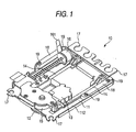
- Fig. 1 shows one example of a related-art optical disk drive unit.
- a disk drive unit 10 comprises a base plate 11 which is supported on a base frame (not shown) by way of four insulators (not shown) formed of elastic material.
- the base plate 11 in Fig. 1 has a flat shape.
- the base plate 11 is provided with: a turntable 12 for clamping an optical disk (not shown) in cooperation with a disk clamper (not shown) thereby to rotate the optical disk; an optical pickup 13 for reproducing, or recording/reproducing information on the optical disk; a guide mechanism 14 which guides the optical pickup 13 in a radial direction of the optical disk; a spindle motor 15 for rotating the turntable 12; and a thread motor 16 for driving the optical pickup 13 by way of a gear mechanism (not shown).
- the base plate 11 has four parts 17 for mounting the above described four insulators respectively at its four corners. Accordingly, the disk drive unit 10 is supported at the four points.
- the spindle motor 15 rotates at high speed rotation number of 6000 rpm or more, thereby generating vibrations in the disk drive unit 10.
- the related-art disk drive unit 10 has a plurality of weight members 18 which are fixed to both side edges of a back face of the base plate 11 with screws 19.
- five sheets of the weight members 18 each having the same weight are employed to be respectively mounted on both the side edges, and the total weight of the weight members 18 is 40 to 50g.
- the total weight of the disk drive unit 10 inclusive of the weight members 18 is 320g.
- a thickness of a sheet of the weight member 18 is 1.2mm, which is equal to a thickness of the base plate 11.
- the related-art disk drive unit 10 having the above described structure, it is impossible to increase the weight of the weight members 18 without limit, because of a limited space. Besides, the plural weight members 18 are mounted only on both the side edges of the back face of the base plate 11, the weight members 18 will not serve to enhance strength of the base plate 11 against a force for twisting or bending the base plate 11.
- It is therefore an object of the invention is to provide an optical disk drive unit in which strength of a base plate against torsion or bending is enhanced.
- an optical disk drive unit comprising:
- the weight member is arranged such that a center of the supporting points is matched with a center of gravity of the optical disk drive unit.
- the weight member is a case-shaped member and the base plate is a flat member.
- the weight member comprises: a first section, extending in a first direction parallel with the base plate, and having a width narrower than a width of the base plate; a pair of second sections, extending in a second direction orthogonal to the first direction from opposed side edges of the first section; and a pair of third sections, each of which extends in the first direction from an end of each of the second sections to be fixed on the base plate.
- one of the opposed side edges of the first section has a width wider than a width of the other one.
- the weight member may be a flat member and the base plate may be a case-shaped member.
- an apparatus for at least one of reproducing and recording information on an optical disk comprising the above optical disk drive unit.
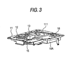
- Figs. 2 through 8E show an optical drive unit 10A according to a first embodiment of the invention.
- the disk drive unit 10A has substantially the same structure and operation as the disk drive unit 10 shown in Fig. 1, except that the weight member 18A has a different shape (structure), as described below. Components similar to those in Fig. 1 will be designated by the same reference numerals and repetitive explanations for those will be omitted.
- the disk drive unit 10A comprises a base plate 11 which is supported on a base frame (not shown) at four points by way of four insulators (not shown) formed of elastic material. As shown in Fig. 4, the base plate 11 has a flat shape. The base plate 11 has a front face 111 and a back face 112, and an opening 11a in a substantially rectangular shape is formed in a center part of the base plate 11.
- a turntable 12 is arranged on the front face 111 of the base plate 11. This turntable 12 is adapted to rotate the optical disk by clamping it in cooperation with a disk clamper (not shown).
- An optical pickup 13 is arranged in the opening 11a of the base plate 11. The optical pickup 13 is for the purpose of reproducing, or recording/reproducing information on the optical disk.
- a guide mechanism 14 is arranged in the opening 11a of the base plate 11. The guide mechanism 14 is for the purpose of guiding the optical pickup 13 in a radial direction of the optical disk.
- a spindle motor 15 is arranged on the back face 112 of the base plate 11. The spindle motor 15 is adapted to rotate the turntable 12.
- a thread motor 16 is arranged on the back face 112 of the base plate 11. The thread motor 16 is adapted to drive the optical pickup 13.
- the weight member 18A is arranged on the back face 112 of the base plate 111.
- the weight member 18A is extended between both side edges of the base plate 11, and fixed to both the side edges of the base plate 11.
- the weight member 18A is arranged on the back face 112 of the base plate 11 at an opposite side to a position where the spindle motor 15 is mounted.
- the weight member 18 has a main face 181 which extends in parallel with the front face 111 of the base plate 11 and has a somewhat shorter width than a width of the base plate 11, a pair of side faces 182 which extend perpendicularly from both side ends of the main face 181, and a pair of fitting parts 183 which extend perpendicularly from a pair of these side faces 182 to be fitted to the base plate 11.
- a thickness of the weight member 18A is the same as a thickness of the base plate 11.
- the weight member 18A has a case-shaped outlook and bridges both the side edges of the base plate 11.
- the main face 181 is provided with an opening 181a in a rectangular shape through which a flexible printed circuit (FPC) (not shown) drawn out from the optical pickup 13 is passed, an opening 181b in a rectangular shape through which a portion of the thread motor 16 is projected, and a pair of round holes 181c through which portions of fixing members for fixing the guide mechanism 14 to the base plate 11 are projected.
- One of the side faces 182 is provided with an opening 182a in a rectangular shape through which a flexible printed circuit (FPC) 161 for supplying electric power to the thread motor 16 is passed.
- FPC flexible printed circuit
- Each of a pair of the fitting parts 183 is provided with four holes 183a. Two of the holes positioned near both ends are holes for passing the screws 19, and the two holes positioned in a center part are holes for positioning.
- the base plate 11 is provided with positioning projections at positions respectively corresponding to these two positioning holes.
- the weight member 18A having the structure as described above is attached to the base plate 11 and fixed with the four screws 19 in a pair of the fitting parts 183.
- the base plate 11 thus has a box-shaped structure. Accordingly, the strength of the base plate 11 against torsion or bending can be enhanced.
- the weight member 18A is arranged at a lower position than the optical pickup 13. Accordingly, it is possible to select a position of the weight member 18A without restriction due to the positions of other components. In this manner, freeness in design, for example, in making fine adjustments of the center of gravity of the disk drive unit 10A will be enhanced, and at the same time, the weight member 18A can be increased in weight.
- Figs. 9 through 10E shows an optical disk drive unit 10B according to a second embodiment of the invention.
- the disk drive unit 10B has substantially the same structure and operation as the disk drive unit 10A of the first embodiment, except that the weight member 18B has a different shape (structure), as described below. Components similar to those in the first embodiment will be designated by the same reference numerals and repetitive explanations for those will be omitted.
- the weight member 18B has such a shape that one side edge of the main face 181A is extended longer toward the spindle motor 15 than the other side edge.
- one of the side faces 182A is made longer than the other side face 182, and one of the fitting parts 183A is also made longer than the other fitting part 183.
- the one fitting part 183A is provided with four holes 183a. Two of the holes positioned near both ends are holes for passing the screws 19, and the two holes positioned in a center part are holes for positioning.
- the other fitting part 183 is provided with three holes 183b. Two of the holes positioned near both ends are holes for passing the screws 19, and one hole positioned in a center part is a hole for positioning.
- the base plate 11 is provided with positioning projections at positions corresponding to these three positioning holes.
- the weight member 18B having the above described structure can be made heavier in weight member than the weight member 18A in the first embodiment.
- the base plate 11 thus has a box-shaped structure. Accordingly, the strength of the base plate 11 against torsion or bending can be enhanced.
- the weight member 18B is arranged at a lower position than the optical pickup 13. Accordingly, it is possible to select a position of the weight member 18B without restriction due to the positions of other components. In this manner, freeness in design, for example, in making fine adjustments of the center of gravity of the disk drive unit 10B will be enhanced, and the center of gravity of the driving mechanism can be moved to such a position that vibrations may be reduced. At the same time, an increase in weight of the weight member 18B can be achieved.
- the box-shaped structure of the disk drive unit is obtained by attaching the case-shaped weighting member to the flat base plate.
- a flat weight member is attached to a case-shaped base plate to obtain the box-shaped structure. It is essential that the weight member bridges the side edges of the base plate.
Landscapes
- Moving Of Heads (AREA)
- Rotational Drive Of Disk (AREA)
- Holding Or Fastening Of Disk On Rotational Shaft (AREA)
- Moving Of The Head For Recording And Reproducing By Optical Means (AREA)
Abstract
Description
Claims (7)
- An optical disk drive unit, comprising:a base frame;a base plate, supported on the base plate by way of a plurality of supporting points;a turntable, on which an optical disk is mounted, the turntable disposed on a first face of the base plate;an optical pickup, adapted at least one of to reproduce and to record information on the optical disk;a guide mechanism, operable to move the optical pickup in a radial direction of the optical disk;a first motor, operable to rotate the turntable;a second motor, operable to drive the guide mechanism; anda weight member, extending so as to bridge opposed side end portions of the second face of the base plate.
- The optical disk drive unit as set forth in claim 1, wherein the weight member is arranged such that a center of the supporting points is matched with a center of gravity of the optical disk drive unit.
- The optical disk drive unit as set forth in claim 1, wherein the weight member is a case-shaped member and the base plate is a flat member.
- The optical disk drive unit as set forth in claim 3, wherein the weight member comprises:a first section, extending in a first direction parallel with the base plate, and having a width narrower than a width of the base plate;a pair of second sections, extending in a second direction orthogonal to the first direction from opposed side edges of the first section; anda pair of third sections, each of which extends in the first direction from an end of each of the second sections to be fixed on the base plate.
- The optical disk drive unit as set forth in claim 4, wherein one of the opposed side edges of the first section has a width wider than a width of the other one.
- The optical disk drive unit as set forth in claim 1, wherein the weight member is a flat member and the base plate is a case-shaped member.
- An apparatus for at least one of reproducing and recording information on an optical disk comprising the optical disk drive unit as set forth in claim 1.
Applications Claiming Priority (2)
| Application Number | Priority Date | Filing Date | Title |
|---|---|---|---|
| JP2004188016 | 2004-06-25 | ||
| JP2004188016A JP2006012291A (en) | 2004-06-25 | 2004-06-25 | Mechanism unit for optical disk drive |
Publications (2)
| Publication Number | Publication Date |
|---|---|
| EP1610310A2 true EP1610310A2 (en) | 2005-12-28 |
| EP1610310A3 EP1610310A3 (en) | 2007-05-02 |
Family
ID=34933986
Family Applications (1)
| Application Number | Title | Priority Date | Filing Date |
|---|---|---|---|
| EP05004363A Withdrawn EP1610310A3 (en) | 2004-06-25 | 2005-02-28 | Optical disk drive unit |
Country Status (3)
| Country | Link |
|---|---|
| EP (1) | EP1610310A3 (en) |
| JP (1) | JP2006012291A (en) |
| CN (1) | CN1713297A (en) |
Family Cites Families (2)
| Publication number | Priority date | Publication date | Assignee | Title |
|---|---|---|---|---|
| TW504669B (en) * | 1998-09-07 | 2002-10-01 | Ind Tech Res Inst | Vibration suppression device of compact disk drive |
| JP4182612B2 (en) * | 1999-09-10 | 2008-11-19 | ソニー株式会社 | Drive device for information recording medium |
-
2004
- 2004-06-25 JP JP2004188016A patent/JP2006012291A/en not_active Withdrawn
-
2005
- 2005-02-28 CN CN200510051131.3A patent/CN1713297A/en active Pending
- 2005-02-28 EP EP05004363A patent/EP1610310A3/en not_active Withdrawn
Also Published As
| Publication number | Publication date |
|---|---|
| JP2006012291A (en) | 2006-01-12 |
| CN1713297A (en) | 2005-12-28 |
| EP1610310A3 (en) | 2007-05-02 |
Similar Documents
| Publication | Publication Date | Title |
|---|---|---|
| US6910218B2 (en) | Slim type optical disc drive | |
| US7698714B2 (en) | Slim optical disc drive | |
| JP2001222877A (en) | Disk unit | |
| KR100480642B1 (en) | Slim type optic disc drive | |
| US6256278B1 (en) | Disc drive equipped with a disc tray having a disc clamper displacement means | |
| CN1977335B (en) | Optical disk apparatus and flexible cable used for the same | |
| JP3928410B2 (en) | Slide cam for disk device and disk device using the same | |
| US7340754B2 (en) | Disk drive device | |
| US7155731B2 (en) | Optical disc drive having a function of preventing an optical disc from being pushed down by turbulence in the air flow generated by the rotation of the optical disc | |
| JP2008210477A (en) | Disk unit | |
| JP2006012291A (en) | Mechanism unit for optical disk drive | |
| CN101231374B (en) | Objective lens driving device and disk device using the same | |
| JP3427666B2 (en) | Disk unit | |
| JP2003016712A (en) | Loading equipment | |
| JP4736827B2 (en) | Optical disk device | |
| JP3805091B2 (en) | Disc player | |
| JP3867855B2 (en) | Optical disk playback device | |
| JPH1125652A (en) | Disc playback device | |
| KR100589601B1 (en) | Loader assembly of optical disc player | |
| JP4361559B2 (en) | Disk unit | |
| CN101661778A (en) | Disc drive apparatus | |
| JPH11195241A (en) | Disc playback device | |
| JP2001222846A (en) | Disk unit | |
| JP2003228864A (en) | Optical head, optical disk drive device and computer device | |
| JP2003317461A (en) | Disk unit case |
Legal Events
| Date | Code | Title | Description |
|---|---|---|---|
| PUAI | Public reference made under article 153(3) epc to a published international application that has entered the european phase |
Free format text: ORIGINAL CODE: 0009012 |
|
| AK | Designated contracting states |
Kind code of ref document: A2 Designated state(s): AT BE BG CH CY CZ DE DK EE ES FI FR GB GR HU IE IS IT LI LT LU MC NL PL PT RO SE SI SK TR |
|
| AX | Request for extension of the european patent |
Extension state: AL BA HR LV MK YU |
|
| PUAL | Search report despatched |
Free format text: ORIGINAL CODE: 0009013 |
|
| AK | Designated contracting states |
Kind code of ref document: A3 Designated state(s): AT BE BG CH CY CZ DE DK EE ES FI FR GB GR HU IE IS IT LI LT LU MC NL PL PT RO SE SI SK TR |
|
| AX | Request for extension of the european patent |
Extension state: AL BA HR LV MK YU |
|
| AKX | Designation fees paid | ||
| STAA | Information on the status of an ep patent application or granted ep patent |
Free format text: STATUS: THE APPLICATION IS DEEMED TO BE WITHDRAWN |
|
| 18D | Application deemed to be withdrawn |
Effective date: 20070301 |
|
| REG | Reference to a national code |
Ref country code: DE Ref legal event code: 8566 |