EP1610167A1 - Progressive refractive power lens - Google Patents
Progressive refractive power lens Download PDFInfo
- Publication number
- EP1610167A1 EP1610167A1 EP04711714A EP04711714A EP1610167A1 EP 1610167 A1 EP1610167 A1 EP 1610167A1 EP 04711714 A EP04711714 A EP 04711714A EP 04711714 A EP04711714 A EP 04711714A EP 1610167 A1 EP1610167 A1 EP 1610167A1
- Authority
- EP
- European Patent Office
- Prior art keywords
- progressive
- power
- lens
- curvature
- power lens
- Prior art date
- Legal status (The legal status is an assumption and is not a legal conclusion. Google has not performed a legal analysis and makes no representation as to the accuracy of the status listed.)
- Withdrawn
Links
Images







Classifications
-
- G—PHYSICS
- G02—OPTICS
- G02C—SPECTACLES; SUNGLASSES OR GOGGLES INSOFAR AS THEY HAVE THE SAME FEATURES AS SPECTACLES; CONTACT LENSES
- G02C7/00—Optical parts
- G02C7/02—Lenses; Lens systems ; Methods of designing lenses
- G02C7/06—Lenses; Lens systems ; Methods of designing lenses bifocal; multifocal ; progressive
-
- G—PHYSICS
- G02—OPTICS
- G02C—SPECTACLES; SUNGLASSES OR GOGGLES INSOFAR AS THEY HAVE THE SAME FEATURES AS SPECTACLES; CONTACT LENSES
- G02C7/00—Optical parts
- G02C7/02—Lenses; Lens systems ; Methods of designing lenses
- G02C7/06—Lenses; Lens systems ; Methods of designing lenses bifocal; multifocal ; progressive
- G02C7/061—Spectacle lenses with progressively varying focal power
- G02C7/068—Special properties achieved by the combination of the front and back surfaces
-
- G—PHYSICS
- G02—OPTICS
- G02C—SPECTACLES; SUNGLASSES OR GOGGLES INSOFAR AS THEY HAVE THE SAME FEATURES AS SPECTACLES; CONTACT LENSES
- G02C7/00—Optical parts
- G02C7/02—Lenses; Lens systems ; Methods of designing lenses
- G02C7/06—Lenses; Lens systems ; Methods of designing lenses bifocal; multifocal ; progressive
- G02C7/061—Spectacle lenses with progressively varying focal power
Definitions
- a progressive-power lens of the present invention pertains to a progressive-power spectacle lens chiefly for a person having poor accomoddation.
- the progressive-power lens comprises a distance portion having refracting power (power) for distant view, a near portion having power for near view, and an intermediate portion which is disposed between the distance and near portions and progressively varies its power.
- the power difference between the distance portion and the near portion is known as addition power, which is set at an appropriate value according to the level of accommodation of a wearer of glasses.
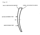
- a spectacle lens also consists of an object-side refractive surface and an eyeball-side refractive surface as illustrated in FIG. 9.
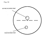
- a typical progressive-power lens has measuring points at which respective power for distant and near views are measured. These points are specified by a lens manufacturer and are in general clearly shown on a refractive surface of a lens by printing or other method as illustrated in FIG. 10. When these points are not printed, the measuring points or other signs can be detected from permanent marks attached to the lens in accordance with the specifications of the manufacturer.
- the points for measuring the power for distant view and near view are referred to as a distance reference point and a near reference point, respectively.
- the refractive surface which is known as a progressive surface and causes addition power peculiar to progressive power, often lies on the object-side refractive surface.
- the eyeball-side refractive surface is formed from a spherical surface or a toric surface with an orientation corresponding to that of a cylinder axis in accordance with a prescribed dioptric power of the wearer of the glasses.
- This type of the progressive-power lens is referred to as an outside surface progressive-power lens in this description.
- the outside surface progressive-power lens has a refractive surface for varying image magnification at the object side, which enlarges image distortion.
- some people who use the progressive-power lens for the first time or who have replaced a differently designed progressive-power lens with the outside surface progressive-power lens may have a sense of incongruity.
- the inside surface progressive-power lens has been recently commercialized in which the progressive surface is disposed at the eyeball side as disclosed in WO97/19382 (FIGS. 4, 10 and 15).
- the inside surface progressive-power lens has a complicated curved-surface configuration in which the object-side refractive surface is formed from a spherical surface or an aspherical surface symmetric with respect to a rotational axis and the eyeball-side refractive surface is from a combination of progressive surface, a toric surface and a corrective aspherical element for correcting off-axis aberration of the lens.
- both-surface progressive-power lens As described in WO97/19383 (FIG. 1), there has been developed and commercially manufactured another type of lens known as a both-surface progressive-power lens which is formed by dividing addition power element of its progressive surface between an object-side refractive surface and an eyeball-side refractive surface. Since the object-side refractive surface includes a part of the progressive surface element for varying magnification, the both-surface progressive-power lens causes larger distortion than the inside surface progressive-power lens having the object-side refractive surface formed from a spherical surface. Of course, the both-surface progressive-power lens causes less distortion than the outside surface progressive-power lens.
- the inside surface progressive-power lens gains addition power by giving curvature difference between the distance portion and the near portion of the eyeball-side refractive surface.
- the curvature of the near portion is smaller than that of the distance portion such that the near portion power is greater than the distance portion power.
- the curvature is negative, the refractive surface at the eyeball side is convex toward the eyeball. This is undesirable in view of manufacture, since a curved surface having a concave at the distance portion and a convex at the near portion requires a more complicated processing technique than the curved surface having concaves at both distance and near portions.
- the curvature at the near portion needs to be established within a range in which it does not become negative.
- the center of the radius of curvature lies closer to the eyeball than to the curved surface when the curvature is positive, and the center of the radius of curvature lies closer to the object than to the curved surface when the curvature is negative, though no distinction between positive and negative is conventionally made for a curvature.
- a refractive index n of a lens base material is 1.67
- a surface power at this curvature can be calculated by a formula of (n-1) X (curvature), obtaining a value of approximately 0.45m -1 .
- the surface power at the distance portion must be larger than that at the near portion by the amount equivalent to the addition power which is to be gained by the inside curved surface.
- addition power 3.00D
- the distance surface power needs to be 3.45D when the near surface power is 0.45D.
- the surface power of the object-side refractive surface needs to be 6.45D as the surface power at the distance portion of the eyeball-side refractive surface is 3.45D.
- the required surface power of the object-side refractive surface is slightly smaller than the above value, considering the effect of central thickness of the lens. However, the effect of central thickness is not taken into account herein for simplifying the explanation.
- the distance portion of the object-side refractive surface needs to have a surface power of 3.45D so as to gain a distance portion power of +3.00D if the eyeball-side refractive surface having a minimum surface power of 0.45D is manufactured.
- the near portion is required to have a surface power of 6.45D to obtain an addition power of 3.00D.
- the radius of curvature of the object-side refractive surface reaches 0.19m corresponding to the power of 3.45D at the upper portion of the lens, and the radius of curvature gradually decreases toward the lower portion of the lens to reach 0.10m corresponding to the power of 6.45D at the near portion.
- the average value thus lies in the range between 3.45D and 6.45D, which makes the height of the convex smaller than that of the inside surface progressive-power lens as described.
- the inside surface progressive-power lens is superior in view of optical characteristics such as less distortion, but is inferior in lens thickness and appearance.
- both-surface progressive-power lens in which the object-side refractive surface has a part of the addition power, it can be easily understood that this lens possesses intermediate characteristics between the outside and inside surface progressive-power lenses.
- the both-surface progressive-power lens involves a higher manufacturing cost due to its complicated processes and longer processing time since the progressive surface is formed from freely curved surfaces having complicated configurations.
- a progressive-power lens for providing a progressive-power lens which is made thin and manufactured at low cost while maintaining optical characteristics of an inside surface progressive-power lens, a progressive-power lens according to the present invention comprises a distance portion, a near portion and an intermediate portion, wherein an object-side refractive surface is formed from a part of an aspherical surface symmetric with respect to a rotational axis and an eyeball-side refractive surface is from a progressive surface.
- the progressive-power lens is characterized in that there is a relationship shown below between a curvature C1 at a distance reference point of the object-side refractive surface and a curvature C2 at a near reference point of the object-side refractive surface: C1 ⁇ C2
- the progressive-power lens is further characterized in that there is a relationship shown below as to a curvature C3 at a portion outward from the near reference point of the object-side refractive surface:
- the progressive-power lens is further characterized in that the eyeball-side refractive surface is formed from a progressive surface to which an aspherical surface element for correcting "as-worn" optical characteristics is added.
- the progressive-power lens is further characterized in that the aspherical surface element for correcting the optical characteristics at the distance portion is different from that element at the near portion.
- the progressive-power lens is further characterized in that the aspherical surface element is established considering any one of a vertex distance at the wearing of glasses, a pantoscopic angle at the wearing of glasses and a working distance.
- the progressive-power lens is further characterized in that the eyeball-side refractive surface is formed from a progressive surface to which an astigmatism-corrective element is added.
- the progressive-power lens is further characterized in that curvature variation ⁇ C1 of the object-side refractive surface satisfies a relationship shown below in a range of 5mm in diameter from a center set at the distance reference point: ⁇ C1 ⁇ 0.25/(n-1) wherein n indicates a refractive index of a lens base material.
- the progressive-power lens is further characterized in that curvature variation ⁇ C2 of the object-side refractive surface satisfies a relationship shown below in a range of 5mm in diameter from a center set at the near reference point: ⁇ C2 ⁇ 0.25/(n-1) wherein n indicates a refractive index of a lens base material.
- the present invention is applicable to the manufacture of a refraction-corrective progressive-power spectacle lens, but its scope is not limited to this.
- FIG. 1 illustrates a concept of a progressive-power lens according to the present invention.
- the most prominent feature of the progressive-power lens of the invention lies at the point that its object-side refractive surface is aspherical and symmetric with respect to a rotational axis, having a smaller curvature C1 at a distance reference point than a curvature C2 at a near reference point.
- an inside surface progressive-power lens a curvature of an object-side refractive surface is determined according to a limited curvature at a near portion of its eyeball-side refractive surface.
- curvatures at a distant portion and a near portion of an object-side refractive surface can be established differently from each other, which allows the curvatures to be determined such that the lens becomes flat.
- an inside surface progressive-power lens is provided that can be made thin by establishing curvatures at a distance portion and a near portion of its object-side refractive surface differently from each other.
- the great difference between the progressive-power lens of the invention and a both-surface progressive-power lens is that the cost for manufacturing the former can be reduced due to its relatively simplified configuration of the object-side refractive surface which is symmetric with respect to the rotational axis.
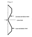
- FIG. 2 shows curvature variation of an object-side refractive surface in a first embodiment.
- an axis passing a geometrical center O of the lens corresponds to a symmetric axis for rotation.
- the lateral axis indicates values of curvature
- the longitudinal axis indicates distance from the center of the lens.
- the upper portion in the figure shows the distance portion
- the lower portion shows the near and intermediate portions.
- the curvature variations are vertically symmetric with respect to the center O.
- the curvature at the distance reference point is smaller than that at the near reference point.
- the surface power at the near portion of the eyeball side refractive surface is set at the processing limit value of 0.45D.
- the surface power at the near portion of the object-side refractive surface needs to be 6.45D.
- the refractive index of the lens n is 1.67
- the curvature C2 at the near portion of the object-side refractive surface becomes 9.63m -1 .
- the curvature C1 at the distance reference point is established at a smaller value than C2, for example, 8.13m -1 in this embodiment.
- This value corresponds to 5.45D when converted into the surface power, which is just 1.00D smaller than the surface power at the near reference point.
- the curvatures at the portions outward from the near reference point and in the vicinity of the rotational axis exhibit smaller values. It is thus easily understood that the average curvature at the convex side is smaller than 9.63m -1 .
- the height of the convex of the progressive-power lens in this embodiment is approximately 0.6mm smaller than that of an inside surface progressive-power lens having a constant curvature of 9.63m -1 of its object-side refractive surface.
- the progressive-power lens of the embodiment is thus improved in appearance. Since the surface power at the distance portion of the object-side refractive surface is 5.45D, the surface power at the distance portion of the eyeball-side refractive surface becomes 2.45D. As the surface power at the near portion is 0.45D, the surface power difference between the distance portion and the near portion of the eyeball-side refractive surface is as small as 2.00D. As is known as a common sense for spectacle lens designers, image distortion decreases in the progressive surface as the surface power difference becomes smaller.
- the progressive-power lens of the invention is improved also in wearing comfortableness.
- FIG. 3 illustrates curvature variation of an object-side refractive surface in a second embodiment.
- constant curvatures are obtained in a range of 5mm in diameter from the centers set at the distance and near reference points.
- the distance and near reference points correspond to the points at which the power is measured for examining lens specifications by means of a lens meter or other apparatus. Since the lens meter generally makes a measurement at the minimum aperture of 5mm in diameter, a stable measurement of power can be taken by reducing the variations in curvature in this range. From the study of the writer of this description, the tolerance of the power sometimes exceeds the standard values specified in Japanese Industrial Standard and International Organization for Standardization when the curvature varies through 0.25D in this range.
- ⁇ C1 is the difference between the maximum and the minimum curvatures in the range of 5mm in diameter from the center set at the distance reference point, the following relationship is obtained: ⁇ C1 ⁇ 0.25 . (n-1) wherein n indicates the refractive index of the lens base material.
- ⁇ C2 is the difference between the maximum and the minimum curvatures in the range of 5mm in diameter from the center set at the near reference point
- the above maximum and minimum curvatures can be easily calculated by applying a commonly used equation for curved surfaces to the data obtained through the three-dimensional geometric measurement at intervals such as 1mm.
- the maximum and the minimum curvatures herein include not only those both at a single optional point within a predetermined portion as described, but also a combination of the maximum curvature at a point having the maximum curvature within the portion and the minimum curvature at another point having the minimum curvature within the portion.
- FIG. 4 illustrates curvature variation in a third embodiment.
- monotonous increase in curvature from the rotational center till the outer periphery can be observed, providing lower improvement in lens thickness compared with the above-described embodiments.
- a highly simplified configuration of an object-side refractive surface allows the manufacturing cost to be reduced considerably.
- FIG. 5 shows curvature variation in a fourth embodiment.
- a rotational center O is positioned closer to a near reference point than to a distance reference point. This example is applicable to a progressive-power lens which places greater emphasis on near views.
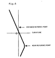
- FIG. 6 illustrates curvature variation in a fifth embodiment.
- a rotational axis of an object-side refractive surface is so designed as to pass not a geometrical center O of the lens, but a near reference point. Since the rotational axis is not disposed at the geometrical center of the lens, higher technique may be required in forming the object-side refractive surface than in the above-described embodiments.
- curvatures can be made smaller in the area other than the near reference point and its vicinity, providing considerable improvement in lens thickness.
- a corrective aspherical surface can be easily added to an eyeball-side refractive surface according to "as-worn" conditions of glasses (such as a vertex distance, a pantoscopic angle at the wearing of glasses and a working distance: see FIG. 13) due to the monotonous variations in curvature.
- FIG. 7 shows curvature variation in a sixth embodiment.
- a rotational shaft is so designed as to pass a distance reference point.
- curvatures of a spectacle lens as references for an object-side refractive surface are variably established in accordance with prescribed dioptric power. Since such specified reference values are not included in the scope of the invention, only variations in curvature have been shown. Curvature difference between distance and near reference points may be set at any value. Curvatures at any positions other than the near reference point and its vicinity are preferably smaller than the curvature at the near reference point. By setting those curvatures in this range, the height of the convex of the object-side refractive surface in the lens of the invention can be made smaller than in an inside surface progressive-power lens, providing improvement in appearance of the lens of the invention.
- the surface power at the distance reference point can be made smaller than that at the near reference point, which decreases the surface power difference of the eyeball-side refractive surface and thus improves image distortion.
- a corrective aspherical surface for providing cylindrical power and adjustment for "as-worn" conditions can be added to the eyeball-side refractive surface.
- the invention can be applied when the dioptric power at the distance portion power is negative.
- the object-side refractive surface becomes a spherical surface having 1.00D in an inside surface progressive-power lens.
- the average surface power becomes larger than that of the inside surface progressive-power lens.
- the height of the convex of the object-side refractive surface increases, but the edge thickness of the lens decreases accordingly.
- the object-side refractive surface of the negative dioptric power lens originally has an almost flat shape, and increase in curvature to some extent does not degrade its appearance. Since the edge thickness is especially noticeable when the lens is fitted to the frame, there is a great demand for a thinner lens to be developed especially from those who use a lens having strongly negative dioptric power.
Landscapes
- Health & Medical Sciences (AREA)
- Ophthalmology & Optometry (AREA)
- Physics & Mathematics (AREA)
- General Health & Medical Sciences (AREA)
- General Physics & Mathematics (AREA)
- Optics & Photonics (AREA)
- Eyeglasses (AREA)
Abstract
Description
Similarly, when ΔC2 is the difference between the maximum and the minimum curvatures in the range of 5mm in diameter from the center set at the near reference point, the following relationship is obtained:
Claims (8)
- A progressive-power lens comprising a distance portion, a near portion and an intermediate portion, wherein an object-side refractive surface is formed from a part of an aspherical surface symmetric with respect to a rotational axis and an eyeball-side refractive surface is from a progressive surface; characterized in that there is a relationship shown below between a curvature C1 at a distance reference point of the object-side refractive surface and a curvature C2 at a near reference point of the object-side refractive surface:
- A progressive-power lens as set forth in claim 1, characterized in that there is a relationship shown below as to a curvature C3 at a portion outward from the near reference point of the object-side refractive surface:
- A progressive-power lens as set forth in claim 1 or 2, characterized in that the eyeball-side refractive surface is formed from a progressive surface to which an aspherical surface element for correcting "as-worn" optical characteristics is added.
- A progressive-power lens as set forth in claim 3, characterized in that the aspherical surface element for correcting the optical characteristics at the distance portion is different from that element at the near portion.
- A progressive-power lens as set forth in claim 3 or 4, characterized in that the aspherical surface element is established considering any one of a vertex distance at the wearing of glasses, a pantoscopic angle at the wearing of glasses and a working distance.
- A progressive-power lens as set forth in any one of claims 1 through 5, characterized in that the eyeball-side refractive surface is formed from a progressive surface to which an astigmatism-corrective element is added.
- A progressive-power lens as set forth in any one of claims 1 through 6, characterized in that curvature variation ΔC1 of the object-side refractive surface satisfies a relationship shown below in a range of 5mm in diameter from a center set at the distance reference point:
- A progressive-power lens as set forth in any one of claims 1 through 7, characterized in that curvature variation ΔC2 of the object-side refractive surface satisfies a relationship shown below in a range of 5mm in diameter from a center set at the near reference point:
Applications Claiming Priority (3)
| Application Number | Priority Date | Filing Date | Title |
|---|---|---|---|
| JP2003041780A JP3882764B2 (en) | 2003-02-19 | 2003-02-19 | Progressive power lens |
| JP2003041780 | 2003-02-19 | ||
| PCT/JP2004/001742 WO2004074907A1 (en) | 2003-02-19 | 2004-02-17 | Progressive refractive power lens |
Publications (2)
| Publication Number | Publication Date |
|---|---|
| EP1610167A1 true EP1610167A1 (en) | 2005-12-28 |
| EP1610167A4 EP1610167A4 (en) | 2010-05-19 |
Family
ID=32905300
Family Applications (1)
| Application Number | Title | Priority Date | Filing Date |
|---|---|---|---|
| EP04711714A Withdrawn EP1610167A4 (en) | 2003-02-19 | 2004-02-17 | PROGRESSIVE REFRINGENCE LENS |
Country Status (6)
| Country | Link |
|---|---|
| US (1) | US7159981B2 (en) |
| EP (1) | EP1610167A4 (en) |
| JP (1) | JP3882764B2 (en) |
| KR (1) | KR100659434B1 (en) |
| CN (1) | CN100347589C (en) |
| WO (1) | WO2004074907A1 (en) |
Families Citing this family (43)
| Publication number | Priority date | Publication date | Assignee | Title |
|---|---|---|---|---|
| US6619799B1 (en) | 1999-07-02 | 2003-09-16 | E-Vision, Llc | Optical lens system with electro-active lens having alterably different focal lengths |
| US7023594B2 (en) * | 2000-06-23 | 2006-04-04 | E-Vision, Llc | Electro-optic lens with integrated components |
| US7775660B2 (en) | 1999-07-02 | 2010-08-17 | E-Vision Llc | Electro-active ophthalmic lens having an optical power blending region |
| US20080106633A1 (en) * | 2002-03-13 | 2008-05-08 | Blum Ronald D | Electro-optic lens with integrated components for varying refractive properties |
| US8778022B2 (en) | 2004-11-02 | 2014-07-15 | E-Vision Smart Optics Inc. | Electro-active intraocular lenses |
| US9801709B2 (en) | 2004-11-02 | 2017-10-31 | E-Vision Smart Optics, Inc. | Electro-active intraocular lenses |
| US8915588B2 (en) | 2004-11-02 | 2014-12-23 | E-Vision Smart Optics, Inc. | Eyewear including a heads up display |
| JP4475654B2 (en) | 2005-05-19 | 2010-06-09 | 東海光学株式会社 | Progressive power lens and manufacturing method thereof |
| US7959285B2 (en) * | 2006-07-20 | 2011-06-14 | Nikon-Essilor Co., Ltd. | Method for designing progressive refraction lens, method for manufacturing the same, and eyeglasses lens supplying system |
| AR064985A1 (en) | 2007-01-22 | 2009-05-06 | E Vision Llc | FLEXIBLE ELECTROACTIVE LENS |
| MX2009008829A (en) * | 2007-02-23 | 2011-10-28 | Pixeloptics Inc | Ophthalmic dynamic aperture. |
| CA2679977A1 (en) * | 2007-03-07 | 2008-09-18 | Pixeloptics, Inc. | Multifocal lens having a progressive optical power region and a discontinuity |
| US7883207B2 (en) | 2007-12-14 | 2011-02-08 | Pixeloptics, Inc. | Refractive-diffractive multifocal lens |
| US20080273169A1 (en) | 2007-03-29 | 2008-11-06 | Blum Ronald D | Multifocal Lens Having a Progressive Optical Power Region and a Discontinuity |
| US20090091818A1 (en) * | 2007-10-05 | 2009-04-09 | Haddock Joshua N | Electro-active insert |
| KR100900090B1 (en) * | 2007-07-10 | 2009-05-28 | 주식회사 드림옵티칼 | Convex Glass Mold for Progressive Multifocal Lens |
| AU2013228002B2 (en) * | 2007-12-14 | 2014-08-07 | Mitsui Chemicals, Inc. | Multiple layer multifocal composite lens |
| US7926941B2 (en) * | 2007-12-14 | 2011-04-19 | Pixeloptics Inc. | Multiple layer multifocal composite lens |
| MX2010006042A (en) * | 2007-12-14 | 2010-06-25 | Pixeloptics Inc | Multiple layer multifocal composite lens. |
| US7744215B2 (en) * | 2007-12-25 | 2010-06-29 | Pixeloptics, Inc. | Multiple layer multifocal composite lens |
| BRPI0908992A2 (en) | 2008-03-18 | 2015-11-24 | Pixeloptics Inc | advanced electro-active optical device |
| US8154804B2 (en) * | 2008-03-25 | 2012-04-10 | E-Vision Smart Optics, Inc. | Electro-optic lenses for correction of higher order aberrations |
| EP2149812B1 (en) * | 2008-07-31 | 2021-08-25 | Hoya Corporation | Progressive-addition lens, method for preparing shape data thereof, method for manufacturing the lens, and apparatus and computer program product for preparing such shape data |
| JP5286473B2 (en) * | 2009-03-31 | 2013-09-11 | ホーヤ レンズ マニュファクチャリング フィリピン インク | Progressive power spectacle lens design method |
| CA3167661A1 (en) | 2012-01-06 | 2013-07-11 | E-Vision Smart Optics, Inc. | Eyewear docking station and electronic module |
| JP6095271B2 (en) * | 2012-03-05 | 2017-03-15 | イーエイチエス レンズ フィリピン インク | Lens set, lens design method, and lens manufacturing method |
| CN106461976B (en) * | 2014-06-04 | 2019-12-06 | 豪雅镜片泰国有限公司 | Progressive-power lens |
| US10288903B2 (en) | 2014-06-04 | 2019-05-14 | Hoya Lens Thailand Ltd. | Progressive addition lens |
| JP6312538B2 (en) * | 2014-06-18 | 2018-04-18 | 株式会社ニコン・エシロール | Lens design method, lens manufacturing method, lens design program, and lens design system |
| CN112946922B (en) * | 2014-08-28 | 2022-10-11 | 香港理工大学 | Design method and lens of free-form progressive lens with corrected astigmatism |
| CN104297942A (en) * | 2014-09-29 | 2015-01-21 | 上海万明眼镜有限公司 | Thinned long-sight glasses lens and preparation method of glasses lens |
| CN104360496A (en) * | 2014-09-29 | 2015-02-18 | 上海万明眼镜有限公司 | Personalized large-front-curvature polarized sunglasses and preparation method thereof |
| CN104297943B (en) * | 2014-10-09 | 2017-09-05 | 河南工业职业技术学院 | Optical glass progressive multifocal lens and its manufacturing method and application |
| JP6483147B2 (en) * | 2014-10-10 | 2019-03-13 | ホヤ レンズ タイランド リミテッドHOYA Lens Thailand Ltd | Progressive power lens |
| KR102580793B1 (en) * | 2015-10-15 | 2023-09-20 | 에씰로 앙터나시오날 | Ophthalmic progressive additive lenses for myopic or emmetropic presbyopia wearers and methods of providing such lenses |
| JP6991135B2 (en) * | 2015-10-15 | 2022-01-12 | エシロール・アンテルナシオナル | How to determine the optical system of a progressive lens |
| JP7055097B2 (en) * | 2015-10-15 | 2022-04-15 | エシロール・アンテルナシオナル | Progressive power lenses for emmetropic and presbyopia wearers and how to provide such lenses |
| DE102015223983A1 (en) * | 2015-12-02 | 2017-06-08 | Carl Zeiss Smt Gmbh | Method for polishing an optical surface and optical element |
| US10599006B2 (en) | 2016-04-12 | 2020-03-24 | E-Vision Smart Optics, Inc. | Electro-active lenses with raised resistive bridges |
| ES2861520T3 (en) | 2016-04-12 | 2021-10-06 | E Vision Smart Optics Inc | Electroactive lenses with high resistive bridges |
| CN105807446B (en) * | 2016-04-18 | 2018-09-11 | 南开大学 | A kind of design method of the optical glasses of correction tubular visual field |
| JP2018112633A (en) * | 2017-01-10 | 2018-07-19 | 伊藤光学工業株式会社 | Progressive power lens |
| JP6707040B2 (en) * | 2017-02-06 | 2020-06-10 | 伊藤光学工業株式会社 | How to design eyeglass lenses |
Family Cites Families (12)
| Publication number | Priority date | Publication date | Assignee | Title |
|---|---|---|---|---|
| JPS5958415A (en) * | 1982-09-29 | 1984-04-04 | Seiko Epson Corp | progressive multifocal lens |
| BE899955A (en) * | 1984-06-19 | 1984-10-15 | Optimed Nv | METHOD FOR PRODUCING A GLASS FOR MYOPES. |
| DE68921432T2 (en) * | 1988-11-29 | 1995-08-10 | Seiko Epson Corp | Eyeglass lens. |
| US6019470A (en) * | 1995-11-24 | 2000-02-01 | Seiko Epson Corporation | Progressive multifocal lens and manufacturing method of eyeglass lens and progressive multifocal lens |
| DE69638108D1 (en) * | 1995-11-24 | 2010-02-25 | Seiko Epson Corp | Multi-strength glass for spectacles and spectacle lenses |
| US5892565A (en) * | 1996-10-18 | 1999-04-06 | Nikon Corporation | Progressive multifocal lens |
| DE19701312A1 (en) * | 1997-01-16 | 1998-07-23 | Zeiss Carl Fa | Spectacle lens with spherical front and multifocal back, and method for its production |
| US6086203A (en) * | 1998-09-03 | 2000-07-11 | Johnson & Johnson Vision Care, Inc. | Progressive addition lenses |
| IL132466A (en) * | 1999-05-20 | 2002-09-12 | Johnson & Johnson Vision Care | Methods for producing progressive addition lenses |
| DE50114292D1 (en) * | 2000-01-17 | 2008-10-16 | Rodenstock Gmbh | GLASSES |
| EP1277076B1 (en) * | 2000-04-25 | 2008-04-02 | Rodenstock GmbH | Progressive spectacle glass |
| US6505934B1 (en) * | 2001-04-27 | 2003-01-14 | Johnson & Johnson Vision Care, Inc. | Progressive addition lenses with prism power added to improve wearer comfort |
-
2003
- 2003-02-19 JP JP2003041780A patent/JP3882764B2/en not_active Expired - Fee Related
-
2004
- 2004-02-17 CN CNB2004800001352A patent/CN100347589C/en not_active Expired - Fee Related
- 2004-02-17 KR KR1020047016801A patent/KR100659434B1/en not_active Expired - Fee Related
- 2004-02-17 WO PCT/JP2004/001742 patent/WO2004074907A1/en not_active Ceased
- 2004-02-17 EP EP04711714A patent/EP1610167A4/en not_active Withdrawn
- 2004-02-17 US US10/504,967 patent/US7159981B2/en not_active Expired - Lifetime
Also Published As
| Publication number | Publication date |
|---|---|
| EP1610167A4 (en) | 2010-05-19 |
| KR100659434B1 (en) | 2006-12-19 |
| CN100347589C (en) | 2007-11-07 |
| CN1697992A (en) | 2005-11-16 |
| US7159981B2 (en) | 2007-01-09 |
| JP3882764B2 (en) | 2007-02-21 |
| KR20050006171A (en) | 2005-01-15 |
| JP2004264365A (en) | 2004-09-24 |
| WO2004074907A1 (en) | 2004-09-02 |
| US20050099596A1 (en) | 2005-05-12 |
Similar Documents
| Publication | Publication Date | Title |
|---|---|---|
| US7159981B2 (en) | Progressive refractive power lens | |
| EP1882973B1 (en) | Design method for spectacle lens, spectacle lens, and spectacles | |
| JP3800629B2 (en) | Multifocal lens for spectacles and spectacle lens | |
| EP0809126B1 (en) | Progressive spectacle lens with progressive surface and correction of astigmatism provided on the rear side of the lens | |
| EP2407815B1 (en) | Method of compiling shape data of a spectacle lens, spectacle lens shape data compiling device and spectacle lens | |
| JP4164550B2 (en) | Progressive power spectacle lens | |
| KR101301566B1 (en) | Ophthalmic lens | |
| EP1917555B1 (en) | Method of making a progressive-power lens | |
| EP1216432A1 (en) | Progressive lens | |
| WO2000073846A1 (en) | Progressive lens | |
| EP1895351A1 (en) | Spectacle lens design method | |
| KR101309003B1 (en) | Ophthalmic lens | |
| JP4192899B2 (en) | Eyeglass lens design method | |
| EP2492740A2 (en) | Progressive power lens and method for designing progressive-power lens | |
| US12228803B2 (en) | Computer implemented method of determining a base curve for a spectacle lens and method of manufacturing a spectacle lens | |
| CN101331421A (en) | Method for determination of an ophthalmic lens | |
| EP3467573A1 (en) | Method for designing vision correction lens, and vision correction lens | |
| KR101228458B1 (en) | Ophthalmic Lens | |
| JP3582527B1 (en) | Progressive power lens and manufacturing method | |
| JP2002122822A (en) | Eyeglass lens | |
| JP2001318344A (en) | Progressive multifocal lens | |
| AU772399B2 (en) | Progressive lens | |
| EP0947871A1 (en) | Multifocal lens | |
| JPH0572503A (en) | Progressive focus lens |
Legal Events
| Date | Code | Title | Description |
|---|---|---|---|
| PUAI | Public reference made under article 153(3) epc to a published international application that has entered the european phase |
Free format text: ORIGINAL CODE: 0009012 |
|
| 17P | Request for examination filed |
Effective date: 20041109 |
|
| AK | Designated contracting states |
Kind code of ref document: A1 Designated state(s): AT BE BG CH CY CZ DE DK EE ES FI FR GB GR HU IE IT LI LU MC NL PT RO SE SI SK TR |
|
| AX | Request for extension of the european patent |
Extension state: AL LT LV MK |
|
| DAX | Request for extension of the european patent (deleted) | ||
| RBV | Designated contracting states (corrected) |
Designated state(s): DE FR GB |
|
| A4 | Supplementary search report drawn up and despatched |
Effective date: 20100421 |
|
| RIC1 | Information provided on ipc code assigned before grant |
Ipc: G02C 7/02 20060101AFI20100415BHEP |
|
| 17Q | First examination report despatched |
Effective date: 20101129 |
|
| STAA | Information on the status of an ep patent application or granted ep patent |
Free format text: STATUS: THE APPLICATION HAS BEEN WITHDRAWN |
|
| 18W | Application withdrawn |
Effective date: 20120925 |