BACKGROUND OF THE INVENTION
Field of the Invention
This invention relates to a battery condition monitor and
a method of monitoring a battery condition, and a method of
detecting a dischargeable capacity of a battery.
Description of the Related Art
A battery installed in a vehicle, especially in an electric
vehicle having a motor as only one driving source, corresponds
to gasoline of a vehicle in which a usual engine is applied to
a driving source. Therefore, recognizing how much the battery
is charged is very important to insure normal driving of the
vehicle.
Usually, to recognize how much the battery is charged, a
voltage at an open circuit of the battery is detected or SOC
(State Of Charge) as following is detected by the voltage at
the open circuit.
SOC[%]={(OCVn - OCVe)/(OCVf - OCVe)}*100
herein, OCVn is a voltage at the open circuit of the current
battery. OCVf is a voltage at the open circuit of the battery
in a full-charged condition. OCVe is a voltage at the open
circuit of the battery in an ended discharge condition, and the
battery cannot be used under the voltage at the open circuit.
SUMMARY OF THE INVENTION
Objects to be solved
The SOC corresponds to an electric charge (Coulomb energy)
stored in the battery. In actual use, all of the electric charge
cannot be used. It is caused by a voltage drop, which is generated
by an internal resistance of the battery when a charging current
flows. The internal resistance is caused by a DC resistance,
concentration polarization and activation polarization of the
battery. A value of the voltage drop is changed by SOC[%], a
value of discharging current, a discharging time and a
temperature. With accordance to a larger value of the voltage
drop, a dischargeable electric charge becomes smaller.
Since, in usual SOC[%], the value of the voltage drop is
not compensated, before SOC becomes zero by OCVn becoming equal
to OCVe, a terminal voltage of the battery at discharging goes
down under OCVe and the battery becomes not dischargeable.
Therefore, a margin for the SOC should be considered. However,
the margin for the SOC is not logical, so that the batter
condition cannot be monitored securely by monitoring only the
SOC.
To overcome the above problem, objects of the present
invention are to provide a battery condition monitor, which can
monitor a battery condition securely and a method of monitoring
the battery condition, and a method of detecting a dischargeable
capacity of a battery for monitoring the battery condition
securely in cases including applying it to the monitor and the
method.
How to attain the object of the present invention
In order to attain the object, a battery condition monitor
for monitoring a condition of a battery according to claim 1
of the present invention monitors a capacity not to be
discharged caused by an internal resistance of the battery.
A battery condition monitor for monitoring a condition of
a battery according to claim 2 of the present invention includes
a dischargeable capacity detector for detecting a dischargeable
capacity corresponding to a value of subtracting a capacity not
to be discharged caused by an internal resistance of the battery
from a charged capacity, and monitors the condition of the
battery based on the detected dischargeable capacity.
A battery condition monitor for monitoring a condition of
a battery according to claim 3 of the present invention includes
a charged capacity detector for detecting a charged capacity,
and a dischargeable capacity detector for detecting a
dischargeable capacity corresponding to a value of subtracting
a capacity not to be discharged caused by an internal resistance
of the battery from a charged capacity, and monitoring the
condition of the battery based on the detected charged capacity
and the detected dischargeable capacity.
A battery condition monitor for monitoring a condition of
a battery according to claim 4 of the present invention is
specified in the battery condition monitor as claimed in claim
1 or 2 in that the dischargeable capacity detector obtains the
dischargeable capacity based on a value of subtracting a voltage
drop caused by the internal resistance during discharging from
an open-circuit voltage at start of discharging corresponding
to discharging the battery.
A battery condition monitor for monitoring a condition of
a battery according to claim 5 of the present invention is
specified in the battery condition monitor as claimed in claim
4 in that the dischargeable capacity detector obtains the
dischargeable capacity by making allowance for a changing value
of a characteristics of a charging condition of the battery and
the open-circuit voltage caused by deterioration.
A battery condition monitor for monitoring a condition of
a battery according to claim 6 of the present invention is
specified in the battery condition monitor as claimed in claim
5 in that the dischargeable capacity detector obtains the
dischargeable capacity, whenever the battery is discharged,
based on a ratio of a first changing value of the open-circuit
voltage of a new battery against reduction of the charging
condition of the battery caused by discharging and a second
changing value of the open-circuit voltage of the battery
against reduction of the charging condition of the battery
caused by discharging, and the value of subtracting.
The battery condition monitor for monitoring a condition
of a battery according to claim 7 of the present invention is
specified in the battery condition monitor as claimed in any
one of claims 4, 5 and 6 in that the dischargeable capacity
detector obtains the dischargeable capacity based on a value
by subtracting a voltage drop by the internal resistance when
a peak current flows in discharging.
A battery condition monitoring method of monitoring a
condition of a battery according to claim 8 includes the step
of monitoring a capacity not to be discharged caused by an
internal resistance of the battery as a capacity not to be
discharged from the battery.
A battery condition monitoring method of monitoring a
condition of a battery according to claim 9 includes the step
of monitoring the condition of the battery based on a
dischargeable capacity corresponding to a value of subtracting
a capacity not to be discharged caused by an internal resistance
of the battery from a charged capacity of the battery.
A battery condition monitoring method of monitoring a
condition of a battery according to claim 10 includes the step
of monitoring the condition of the battery based on a charged
capacity of the battery, and a dischargeable capacity
corresponding to a value of subtracting a capacity not to be
discharged caused by an internal resistance of the battery from
the charged capacity.
A battery condition monitoring method of monitoring a
condition of a battery according to claim 11 includes the step
of obtaining the dischargeable capacity based on a value of
subtracting a voltage drop caused by the internal resistance
during discharging from an open-circuit voltage corresponding
to a charged capacity of the battery.
BRIEF DESCRIPTION OF THE DRAWINGS
Fig. 1 is a block diagram of one embodiment of a battery
condition monitor performing a method of detecting a
dischargeable capacity and a method of monitoring a battery
condition according to the present invention;
Fig. 2 is a graph showing one example of a discharge current
with a rush current at starting of driving a starter motor;
Fig. 3 is a graph showing an example of characteristics
of I-V by an approximate quadratic equation;
Fig. 4 is a graph showing an example of method of deleting
a part by concentration polarization from an approximate
equation of increasing;
Fig. 5 is a graph showing an example of a method of deleting
a part by concentration polarization from an approximate
equation of decreasing;
Fig. 6 is a graph showing an example of characteristics
of I-V by an approximate linear equation of increasing;
Fig. 7 is a graph showing an example of the other method
of deleting a part by concentration polarization from an
approximate equation of decreasing;
Fig. 8 is a graph showing an example of a furthermore method
of deleting a part by concentration polarization from an
approximate equation of decreasing;
Fig. 9 is a graph for explaining a method of obtaining a
saturated polarization in discharging in a balanced condition
or a condition having discharging polarization;
Fig. 10 is a graph for explaining a method of obtaining
a saturated polarization in discharging in a condition having
charging polarization;
Fig. 11 is a graph for explaining a method of obtaining
a saturated polarization in discharging in a condition having
discharging polarization or charging polarization;
Fig. 12 is a graph for explaining parts of voltage drop
generated in the battery in discharging;
Fig. 13 is a graph for explaining a voltage at full-charge
and a voltage at the end of discharge;
Fig. 14 is a graph for explaining a method of calculating
the dischargeable capacity counting deterioration by obtaining
a ratio of change of an open-circuit voltage corresponding to
a change of any charge condition of the battery at ant time
against a new battery;
DESCRIPTION OF THE PREFERRED EMBODIMENT
Before describing a battery condition monitor and a method
of monitoring a battery condition, and a method of detecting
a dischargeable capacity of a battery according of the present
invention with reference to Fig. 1, a calculating method of a
voltage drop caused by an internal resistance of the battery
with reference to Figs. 2-14 will be described.
In a 12V car, a 42V car, an EV car and an HEV car having
a battery, a constant load such as a starter motor, a motor
generator and a drive motor, which requires large current, is
installed as a vehicle load acting by supplied power from the
battery. When a large current constant load like the starter
motor is turned ON, after a rush current flows in the constant
load, a constant current corresponding to a value of the load
flows. When the load is a lamp, the rush current is called an
inrush current.
When a direct-current motor is applied to the starter motor,
the rush current flowing in a field coil increases from zero
to a peak value as few times large as that of the constant current,
for example 500 [A] , monotonously in a short time such as 3 msec.
just after starting driving the constant load as shown in Fig.
2. After that, the current decreases from the peak value to the
constant value corresponding to the constant load monotonously
in a short time such as 150 msec. Thus, the current is supplied
as a discharge current by the battery. Therefore, by measuring
the discharge current of the battery and a terminal voltage
corresponding to the discharge current when the rush current
flows in the constant load, characteristics of the discharge
current (I) of the battery and the terminal voltage (V) , which
shows a change of the terminal voltage against a wide-range
change of the current from zero to the peak value, can be
measured.
The battery is discharged by an electronic load, in which
the current increases from zero to 200 [A] in 0.25 sec. and
decreases from the peak value to zero in the same time, as a
approximated discharge corresponding to the rush current
flowing when the starter motor is turned ON. By measuring a pair
of the discharge current of battery and the terminal voltage
in a short constant period, and plotting the measured pair of
data to correspond the discharge current to a horizontal axis
and the terminal voltage to a vertical axis, a graph shown in
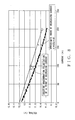
Fig. 3 is given. The characteristics of the current-voltage in
increasing and decreasing discharge current shown in Fig. 3 can
be approximated to flowing quadratic equations by a least
squares method.
V = a1*I2 + b1*I + c1
V = a2*I2 + b2*I + c2
In Fig. 3, curves of approximated quadratic equations are
drawn to overlap on.
In Fig. 3, a voltage difference (c1-c2) between an
intersection point of the approximated curve of increasing
current and an intersection point of the approximated curve of
decreasing current is a voltage difference at no current of zero
[A]. Then, the voltage difference is considered as a voltage
drop caused only by a part by the concentration polarization
newly occurred by discharging, not including the direct-current
resistance and the activation polarization. Therefore, the
voltage difference (c1-c2) is caused only by the concentration
polarization, and the concentration polarization at the current
of zero [A] is called Vpolc0. Any concentration polarization
is considered as a value of multiplying a current value and a
time of current flowing together, which is in proportion to A*h
(or A*sec because of short time)
A method of calculating a concentration polarization at
the peak current by using the concentration polarization at the
current of zero [A] Vpolc0 will be described. The concentration
polarization at the peak current is called Vpolcp. Vpolcp is
shown by the following equation.
Vpolcp = [(A*sec at increasing current)/(A*sec at total
time for discharging)] * Vpolc0
A*sec at total time for discharging is shown by the
following equation.
A*sec at total time for discharging = (A*sec at increasing
current + A*sec at decreasing current)
By adding the concentration polarization Vpolcp at the peak
value as calculated above to the voltage at the peak value of
increasing current of equation (1), the part by the
concentration polarization at peak value is deleted as shown
in Fig. 4. A voltage after deleting the part by the concentration
polarization at peak value is called V1. V1 is shown in the
following equation.
V1 = a1*Ip2 + b1*Ip + c1 + Vpolcp
Ip is the current at the peak value.
An approximate equation of the characteristics of
current-voltage of the direct-current resistance and the
activation polarization as shown in Fig. 4 is tentatively shown
as the following equation.
V = a3*I2 + b3*I + c3
Since the activation polarization and the concentration
polarization at the current of zero [A] before start of
discharging is considered based on c1, c3=c1 is given by the
equation (1). Assuming that the current increases rapidly from
an initial condition of increasing the current, but reaction
of the concentration polarization is slow and the reaction is
almost not proceeded, differential values of the equations (1)
and (4) at the current of zero [A] becomes equal to each other
so that b3=b1 is given. Therefore, by substituting c3=c1 and
b3=b1, the equation (4) will be rewritten as the followings.
V = a3*I2 + b1 I + c1
a3 is the only unknown quantity.
After that, assigning a coordinate of the peak of increasing
current to the equation (5) , and straightening it about a3, the
following equation can be given.
a3 = (V1 - b1*Ip - c1)/Ip2
Thus, the approximate equation of the current-voltage
characteristics only by the direct-current resistance and a
part by the activation polarization is given by the equation
(5).
Usually, the direct-current resistance is not generated
by a chemical reaction, so that it is constant if the charging
condition of battery (SOC) and temperature are not changed. The
resistance is constant while the initial driving of the start
motor. On the other hand, the activation polarization is a
resistance generated by a chemical reaction during exchanging
ions and electrons. The activation polarization and the
concentration polarization affect to each other, so that the
current increasing curve and the current decreasing curve of
the activation polarization are not completely accordant with
each other. Therefore, the equation (5) can be considered as
a curve of increasing current of the direct-current resistance
and the activation polarization excluding the part by the
concentration polarization.
A method of deleting the part by the concentration
polarization from the decreasing current curve will be
described as follows. An equation of decreasing current of the
direct-current resistance and the activation polarization can
be given by the same method of deleting the concentration
polarization at the current peak value. Defining two points
other than the peak value as points A and B, concentration
polarization VpolcA, VpolcB at the points A and B is given by
the following equations.
VpolcA = [(A*sec from start of increasing current to point
A)/(A*sec at total time for discharging)] * Vpolc0
VpolcB = [(A*sec from start of increasing current to point
B)/(A*sec at total time for discharging)] * Vpolc0
By using coordinates of three point of two points of
deleting the part by concentration polarization other than the
peak value given by the above equations (6), (7), and the peak
value, a curve of decreasing current of the direct-current and
the activation polarization shown by the following equation is
given as shown in Fig. 5.
V = a4*I2 + b4*I + c4
Coefficients a4, b4, c4 in the equation (8) can be
determined by solving three simultaneous equations by assigning
the current values and the voltages of the three points of points
A, B and the peak point into the equation (8).
A method of calculating the direct-current resistance of
the battery will be described. A difference between the curve
of increasing current of the direct-current resistance and
activation polarization excluding the concentration
polarization shown by the above equation (5), and the curve of
decreasing current of the direct-current resistance and
activation polarization excluding the concentration
polarization shown by the above equation (8) is according to
the difference of the part by the activation polarization.
Therefore, by deleting the part by the activation polarization
from the above curves, the direct-current resistance can be
given.
Watching the peak value of the both curves those the
activation polarization is the same value to each other, a
differential value R1 of increasing current and a differential
value R2 of decreasing current at the peak value are given by
the following equations.
R1 = 2*a3*Ip + b3
R2 = 2*a4*Ip + b4
A difference between the differential values R1 and R2 is
caused by that one is the peak value of increasing of the
activation polarization and the other is the peak value of
decreasing. When the battery is discharged by using the
electronic load to discharge as increasing from zero to 200 A
within 0.25 sec and decreasing from the peak value to zero within
the same time as a approximated discharge corresponding to the
rush current, the both rates of change in the vicinity of the
peak value are equal to each other, and it is considered that
the characteristics of current-voltage by the direct-current
resistance exists between the both. Therefore, by adding the
differential values and dividing that by 2, the direct-current
resistance R can be given by the following equation (in this
example, a value of dividing proportionally the both
differential value by a ratio of time and a value divided by
2 are the same).
R = (R1 + R2)/2
A case that the battery is discharged by using the
electronic load as the approximated discharge corresponding to
the rush current is described above. In case of actual vehicle,
during the rush current flows in the field coil, the current
reaches up to the peak, and cranking is acted by a current
decreased down under the half of the peak current after reaching
peak.
Therefore, the increasing current finishes in a short time
of 3 msec. Such rapid current change almost never generate the
concentration polarization at the peak value of the increasing
current. The decreasing current flows in a long time of 150 msec
comparing with the increasing current, so that, although
decreasing current, a large concentration polarization is
generated. During cranking, different phenomenon other than
that during the rush current flows occurs. Discharge current
and terminal voltage of the battery during cranking are not
applied as data to determine the characteristics of
current-voltage of decreasing current.
In such condition, the increasing current in the actual
vehicle can be approximated by a straight line made with two
points of a start point of increasing current and a peak value,
as shown in Fig. 6. Generated value of the concentration
polarization at the peak value of 500 [A] can be judged as zero
[A]. In this case, a differential value at the peak value of
increasing current uses a gradient of the approximated line of
the increasing current.
In this case, a simple arithmetic average of the gradient
of the approximated line of the increasing current and a
gradient of a tangential line at the peak point of the
approximated quadratic equation of the decreasing current
cannot be applied. In such condition, generation of the
concentration polarization completely differs between to-peak
and after-peak, so that an assumption that the both ratios of
change at the peak value are the same is not realized.
The direct-current resistance in this case is obtained by
multiplying respectively change values per a unit of a current
change of two terminal voltages at points corresponding to peak
values of the first and second change values excluding the
voltage drop by the concentration polarization, those are
gradients, and ratios of times of monotonously increasing and
monotonously decreasing against the total time of rush current
flowing, and adding the results. In short, proportional ratios
those are distributed by the monotonously increasing time
against the total time and the monotonously decreasing time
against the total time are multiplied with the each gradient
and the result are added. Thereby, compensating an effect caused
to each other by the activation polarization and the
concentration polarization, the direct-current resistance can
be obtained.
The activation polarization is generated in principal to
have a value corresponding to the current. However, The value
is affected by an amount of the concentration polarization, so
that the value is not generated in principal. The smaller
concentration polarization makes the activation polarization
smaller, and the larger concentration polarization makes the
activation polarization larger. In any case, the middle value
between two changes per a unit of current-change of the terminal
voltages at the points corresponding to the peak values of the
two approximate equations excluding the voltage drop by the part
by the concentration polarization can be measured as the
direct-current resistance of the battery.
In a recent vehicle, an AC motor such as a magnet motor
and a brushless DC motor, which requires a three-phase input
power is used more frequently. In such motor, the rush current
does not reach a peak value in a short time. It requires
approximate 100 msec and the concentration polarization is
generated in creasing current. Therefore, as same as the
simulated discharging mentioned above, the current change curve
of the increasing current must be approximated with a curve.
When approximating the direct-current resistance and the
activation polarization at the decreasing current, for defining
the peak value and two points other than the peak by applying
the point of the current of zero [A] as the point B as shown
in Fig. 7, calculation to obtain the approximate equation can
be simplified.
If defining a point, a current of which is approximately
half of the peak current, as a point where the concentration
polarization is deleted, it can be linearly approximated to a
straight line made by this point and the peak value. In this
case, regarding the decreasing current, the gradient of the
approximated straight line at the decreasing current is used
as the differential value at the peak value. The direct-current
resistance can be obtained accurately as same as that by using
the quadratic curve.
In short, the middle value between two changes per the unit
of current-change of the terminal voltages at the points
corresponding to the peak values of the two approximate
equations excluding the voltage drop by the part by the
concentration polarization can be measured as the direct-current
resistance of the battery.
In the case of using for example the starter motor, where
a rush current flowing with generating the concentration
polarization at the both of increasing discharging current and
decreasing discharging current as the constant load, the method
of measuring the direct-current resistance of the battery
mounted on the vehicle will be described physically.
When the constant load is acted, the discharge current
increasing monotonously over a steady-state value to peak value,
and decreasing monotonously form the peak value to the
steady-state value flows from the battery. The discharge
current and the terminal voltage of the battery at the time are
sampled at intervals of for example 100 micro-sec to measure
them periodically, so that many couples of the discharge current
and the terminal voltage are obtained.
The latest couple of the discharge current and the terminal
voltage of the battery obtained above are stored, memorized and
collected in a memory as rewritable storage device such as a
RAM in a predetermined time. By the least-squares method, from
couples of the discharge current and the terminal voltage stored,
memorized and collected in the memory, two curved approximate
equations (1) and (2) regarding to the characteristics of
current-voltage of increasing discharging current and
decreasing discharging current which show a relation between
the terminal voltage and the discharging current. By deleting
the voltage drop of the part by concentration polarization from
the two approximate equations, an amended curved approximate
equations excluding the part by the concentration polarization.
The voltage difference of the approximate equations (1)
and (2) at the current of zero [A], flowing no current, is
obtained as the concentration polarization, not as the voltage
drop by the direct-current resistance and the activation
polarization. The voltage drop of the part by concentration
polarization at the peak value at the approximate equation (1)
of characteristics of current-voltage of the increasing
discharging current is obtained with the voltage difference.
For that, the fact that the concentration polarization changes
by a product of current-time, which is given by multiplying a
value of current and a time of current flowing, is used.
After the voltage drop of the part by concentration
polarization at the peak value at the approximate equation (1)
of characteristics of current-voltage of the increasing
discharging current is obtained, the constant and the
coefficient of a leaner term of the approximate equation
including the part of the concentration polarization are made
the those of the approximate equation not including the part
respectively the same. A coefficient of a quadratic term of the
approximate equation not including the part is defined by that.
Thereby, the amended curved approximate equation (5) of the
approximate equation of the characteristics of current-voltage
of the increasing discharging current is obtained.
After that, the approximate equation not including the part
of concentration polarization will be given by the approximate
equation (2) of the characteristics of current-voltage of the
decreasing the discharging current. For that, two points
deleting the part of the concentration polarization other than
the peak value are obtained. For that, the fact that the
concentration polarization changes by a product of current-time,
which is given by multiplying a value of current and a
time of current flowing, is used. When two points deleting the
part by concentration polarization other than the peak value
are obtained, the amended curved approximate equation (8),
which is the approximate equation (2) of characteristics of
current-voltage of the decreasing current amended by using
three coordinates of the two points and the peak value is
obtained.
The difference between the amended curved approximate
equation, shown by equation (5), of the increasing current of
the direct-current resistance and the activation polarization
by deleting the part by the concentration polarization and the
amended curved approximate equation, shown by equation (8) , of
the decreasing current of the direct-current resistance and the
activation polarization by deleting the part by the
concentration polarization is caused by the part by activation
polarization. Therefore, the direct-current resistance can be
given by deleting the part by the activation polarization. The
difference between the differential values at the peak values
of the increasing current and the decreasing current is caused
by that the activation polarization of one is increasing and
that of the other is decreasing. By watching the peak values
of the both approximate equations, At a middle point between
ratios of changes of the both in the vicinity of the peak value,
the characteristics of current-voltage by the direct-current
resistance exits. Therefore, the direct-current resistance can
be obtained by multiplying the both differential values and
respectively the time ratio in increasing monotonously and the
time ratio in decreasing monotonously, and adding the results.
For example, assuming that the time of the increasing
current is 3 msec, and the time of the decreasing current is
100 msec, and defining the differential value of the increasing
current at the peak value as Rpolk1, and the differential value
of the decreasing current at the peak value as Rpolk2, the
direct-current resistance Rn can be calculated as follows.
Rn = Rpolk1*100/103 + Rpolk2*3/103
The direct-current resistance Rn is calculated and renewed
whenever a high efficient discharge generating rush current is
acted for example, each time when driving the start motor.
The terminal voltage of the battery measured in a balanced
condition which effects of polarization generated in the
battery by previous discharge is eliminated completely and the
voltage down or up of the terminal voltage of the battery is
eliminated completely, or an estimated value by the result of
detecting a change of the terminal voltage of the battery just
after stopping charging/discharging in a short time range is
used as the voltage at open-circuit of the battery for the
vehicle at the balanced condition of the battery is used.
A method of detecting a saturated polarization of the
battery and the method of detecting dischargeable capacity
according to the present invention will be described.
An energy of the battery to be discharged actually for a
load is a capacity by subtracting a capacity corresponding to
the voltage drop generated in the battery during discharging,
that is the capacity to be not dischargeable by the internal
resistance of the battery, from the charged capacity (product
of the current and the time) corresponding to the value of
open-circuit voltage of the battery.
The voltage drop generated in the battery during
discharging can be divided to a part of the voltage drop (IR
drop shown in Figure) by the direct-current resistance of the
battery and a part of the voltage drop by the other internal
resistance than the direct-current resistance, that is a part
of the voltage drop by polarization (saturated polarization
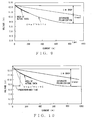
shown in Figure) as shown in Fig. 9.
The above IR drop is not changed when the battery is in
the same condition. On the other hand, the voltage drop by the
polarization enlarges proportionally with the discharge
current or discharge time, but becomes not over the saturated
polarization. Therefore, by monitoring a point of approaching
the saturated polarization, a point of most increasing the
voltage drop by the internal resistance can be monitored.
When the battery, which is in the balanced condition or
in a condition of which the terminal voltage at staring
discharge has a discharge polarization lower than an open-circuit
voltage OCV0 at starting discharge, is discharged, an
approximate equation of the terminal voltage V against the
discharge current I shown by equation (12) is obtained by the
discharge current and the terminal voltage of the battery
measured in intervals within a predetermined period (appearing
polarization and within 1 sec) from the starting discharge, as
a wide line shown in Fig. 9.
On the other hand, when the battery, which is in a condition
of which the terminal voltage at staring discharge has a
discharge polarization larger than the open-circuit voltage
OCV0 at starting discharge, is discharged, an approximate
equation of the terminal voltage V against the discharge current
I shown by equation (12) is obtained by the discharge current
and the terminal voltage of the battery measured in intervals
within a predetermined period when the predetermined period
passes from the starting discharge to eliminate the discharge
polarization, as a wide line shown in Fig. 10. The approximate
equation obtained by the discharge current and the terminal
voltage of the battery measured in intervals within a period
when the discharge polarization exists has almost no relation
between the actually obtained characteristics of the discharge
current I and the terminal voltage V when discharging from the
balanced condition.
V = a*I2 + b*I + c
The above terminal voltage V of the battery can be also
shown as follows by the sum of a part of the voltage drop by
the direct-current resistance Rn and a part of the voltage drop
VR (voltage drop by polarization) by the internal resistance
other than the part by the direct-current resistance.
V = c - (Rn*I + VR)
The following equation can be led from the equations (12)
and (13).
a*I + B*I = -(Rn*I + VR)
By differentiating the above equation (14), the change
ratio dVR/dI of the voltage drop by internal resistance other
than the direct-current resistance of the battery can be
obtained.
dVR/dI = -2a*I - b - Rn
When the above change ratio dVR/dI becomes to zero, the
discharge current corresponds to a saturated current of the
terminal voltage drop Ipo1 (= -(Rn + b)/2a) when the part by
internal resistance other than the direct-current resistance
of the battery becomes the maximum value (the saturated value).
When the discharge is from the balanced condition, by
assigning the obtained saturated current of the terminal
voltage drop Ipo1 as the discharge current I and the
direct-current resistance Rn together into the equation (14) ,
an obtained voltage drop VR (= -a*Ipol2 - b*Ipol - Rn*Ipol) by
polarization is defined as a saturated polarization VRpol.
On the other hand, when discharge is from the condition
in which the charge polarization or the discharge polarization
exists, by assigning the obtained saturated current of the
terminal voltage drop Ipo1 as the discharge current I and the
direct-current resistance Rn together into the equation (14) ,
a value by adding the obtained voltage drop VR by polarization
and the terminal voltage c at the discharge current of zero
obtained by the equation (12) and the obtained difference
between the open-circuit voltage OCV0 at starting discharge (=
-a*Ipol2 - b*Ipol - Rn*Ipol + (OCV0 - c)) is defined as a saturated
polarization VRpol.
The reason of adding (OCV0 - c) mentioned above will be
explained as follows. The terminal voltage at the discharge
current of zero is shown in Fig. 11 to be given by the obtained
approximate equation (12) based on the discharge current and
the terminal voltage measured from the condition of remaining
the charge polarization or the discharge polarization within
the above predetermined period. As shown in Fig. 11, the
saturated value of the voltage drop obtained by the approximate
equation is equal to the saturated value of the voltage drop
of the characteristics of the current I and the voltage V
actually given after discharging from the balanced condition.
Even if the discharge is in the condition of remaining the
charge polarization, by setting a predetermined time passing
after discharging as the predetermined period, the terminal
voltage c at the discharge current of zero obtained by the
approximate equation is a lower value than the open-circuit
voltage at the start of discharge OCV0.
At the time, the voltage drop of polarization obtained by
assigning Ipol to the equation (14), VR (= -a*Ipol2 - b*Ipol
- Rn*Ipol) , is equal to a value of subtracting the voltage drop
by the direct-current resistance Rn*Ipol from the voltage drop
based on the terminal voltage c. Therefore, for obtaining the
saturated polarization Vpol, as the value of subtracting the
voltage drop by the direct-current resistance Rn*Ipol from the
voltage drop of the battery, from the open-circuit voltage OCV0,
it is required to add (OCV0 - c) to the above voltage drop VR
(= -a*Ipol2 - b*Ipol - Rn*Ipol). The VRpol is calculated and
renewed at every discharge of the battery.
After obtaining the saturated polarization VRpol, the
dischargeable capacity can be detected by every discharge,
which requires to detect again the dischargeable capacity of
the battery, by using the saturated polarization VRpol, as
described below.
When discharging, the saturated polarization VRpol is
obtained as mentioned above in the discharging, and a following
equation is solved.
VADC = OCV0 - Rn*Ip - VRpol
herein, VADC is a voltage indicating the present
dischargeable capacity and Ip is the peak current of the
discharge.
Solving the above equation means to obtain the voltage VADC
corresponding to a present dischargeable capacity of the
battery ADC by subtracting the voltage drop corresponding to
the direct-current resistance of the battery and the saturated
polarization VRpol from the open-circuit voltage of the battery
at the start of discharge OCV0, as shown in Fig. 12.
From the voltage indicating the present dischargeable
capacity VADC obtained above, the dischargeable capacity ADC is
given by a following converting equation in a voltage system.
ADC = SOC*{(VADC - Ve)/(Vf - Ve)}*100 [%]
herein
SOC = {(OCVn - Ve)/(Vf - Ve)}*100 [%]
Vf is a voltage at a full-charge, and Ve is a voltage at
the end of discharge.
The voltage at the full-charge Vf is given by the following
equation of subtracting a voltage drop corresponding to the
direct-current resistance at the full-charge (SOC:State Of
Charge=100%) of a new battery Rnf0 from the open-circuit voltage
at the full-charge (SOC=100%) of a new battery OCVf.
Vf = OCVf - Rnf0*Ip
The voltage at the end of discharge Ve is given by the
following equation of subtracting a voltage drop corresponding
to the direct-current resistance at the end of discharge
(SOC=0%) of a new battery Rne0 from the open-circuit voltage
at the end of discharge (SOC=0%) of a new battery OCVe.
Ve = OCVe - Rne0*Ip
From the voltage indicating the present dischargeable
capacity VADC obtained above, the dischargeable capacity ADC can
be given by the following converting equation in a voltage
system.
ADC = SOC*{(VADC - OCVe)/(OCV0 - Rne0*Ip -OCVe)}*100%
In the voltage drop corresponding to the direct-current
resistance of the battery, which is subtracted from the
open-circuit voltage of the battery at the start of discharge
OCVn, differences of characteristics between each battery is
reflected. In the present saturated polarization of the battery
VRpol, dispersion of decreasing of the dischargeable capacity
ADC caused by flowing the discharge current and dispersion of
decreasing of the dischargeable capacity ADC caused by change
of the internal resistance by temperature change are reflected.
Therefore, the dischargeable capacity to be obtained at
discharge ADC obtained above is accurate dischargeable capacity
ADC excluding errors by an effect of differences of
characteristics between each battery and effects of dispersion
of decreasing of the dischargeable capacity ADC caused by
flowing the discharge current and dispersion of decreasing of
the dischargeable capacity ADC caused by change of the internal
resistance by temperature change.
As mentioned above, the voltage drop by the internal
resistance at the peak current in discharge, that is the voltage
drop by the internal resistance at a time when the voltage drop
by the direct-current resistance of the internal resistance
other than the polarization becomes in the maximum, can be
obtained.
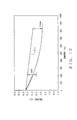
As shown in Fig. 14, when discharging a battery in any
open-circuit voltage OCV0 before discharge, the open-circuit
voltage of the new battery decreases along a straight line N
in proportion to proceeding of discharge until the open-circuit
voltage OCVn at end of discharge to discharge any electric
charge. The open-circuit voltage of a deteriorated battery
decreases along a straight line M until the open-circuit voltage
OCVm at the time to discharge the same electric charge.
Usually, after repeating discharge, the charge condition
SOC can be estimated by a product of the current and the time.
The charge condition can be calculated by summing the product
of the current and the time at discharge as following equation.
SOC0 just before discharge - Σ ((discharge current)*time)
Whenever the battery is in discharge, the SOC of the battery
can be estimated by the above equation.
As mentioned above, by always obtaining the estimated SOCn
in discharge, and estimating the last SOCn at end of discharge
when discharge is stopped, the estimated value is converted to
an estimated OCVn. The conversion of the SOCn to OCVn is acted
based on an initial electric charge as the total chargeable
electric charge between the open-circuit voltage at full-charge
and the voltage at end of discharge predetermined for the new
battery.
A change rate ΔOCVn (=OCV0 - estimated OCVn) as a difference
between the open-circuit voltage before discharge OCV0 and the
above estimated OCVn is a change rate for calculation of the
open-circuit voltage of the new battery against decrease of the
charge of the battery by discharge.
A change rate ΔOCVm (=OCV0 - estimated OCVm) as a difference
between the open-circuit voltage before discharge OCV0 and the
OCVm measured after discharge or estimated is a change rate of
the open-circuit voltage of the present battery against
decrease of the charge of the battery by discharge.
Even if the battery is in the balanced condition or not,
by multiplying ΔOCVn/ΔOCVm, a ratio of the change rate ΔOCVn
and the change rate ΔOCVm to a right-hand side of the converting
equation in the voltage system for obtaining the dischargeable
capacity ADC from the voltage indicating the present
dischargeable capacity VADC, the converting equation for
obtaining the dischargeable capacity ADC from the voltage
indicating the present dischargeable capacity VADC will be as
following.
ADC = {(VADC - Ve) / (Vf - Ve)}*(ΔOCVn/ΔOCVm)*100 [%]
or
ADC = SOC*{(VADC - OCVe) / (OCVn - Rne0*Ip - OCVe)} *
(ΔOCVn/ΔOCVm)* 100%
Thereby, even if inactivation exists in an active material
of the battery, a more accurate dischargeable capacity can be
obtained by counting the change of the open-circuit voltage OCVn
corresponding to the change of charge condition by the
inactivation.
Modification of the converting equation of obtaining the
dischargeable capacity ADC from the voltage indicating the
present dischargeable capacity VADC for corresponding to a
change of a ratio of amounts of the activation material and H2O
of the battery can be eliminated.
As mentioned above, the value of adding the voltage drop
by polarization VR (= -a*Ipol2 - b*Ipol - Rn*Ipol) obtained by
assigning Ipol to the equation (14) for obtaining the saturated
polarization at discharge from the condition of remaining the
charge polarization or the discharge polarization and (OCV0 -
c) is defined as the saturated polarization. Even if the
polarization is remained, and the battery is in the balanced
condition or not, to obtain the voltage drop by polarization
VR (= -a*Ipol2 - b*Ipol - Rn*Ipol) given by assigning Ipol to
the equation (14) as the saturated polarization, the voltage
VADC can be calculated by subtracting (OCV0 - c) from the
open-circuit voltage OCV0.
The method of calculating the dischargeable capacity of
the battery for the vehicle and the method of monitoring the
battery condition according to the present invention are
performed in a structure shown in Fig. 1.
Fig. 1 is a block diagram of one embodiment of a battery
condition monitor to perform the method of calculating the
dischargeable capacity and the method of monitoring the battery
condition according to the present invention. The battery
condition monitor of the embodiment shown with mark 1 in Fig.
1 is installed in a hybrid vehicle with a motor generator 5 added
on an engine 3.
In the hybrid vehicle, an output power of the engine 3 is
transmitted from a drive shaft 7 through a differential case
9 to a wheel 11 for normal driving. At high load condition, the
motor generator 5 is performed as a motor by electric power of
a battery 13 and an output of the motor generator 5 added on
the output of the engine 3 is transmitted from the drive shaft
7 to the wheel 11 for assist driving.
In the hybrid vehicle, the motor generator 5 is performed
as a generator at decelerating and breaking to convert kinetic
energy to electric energy for charging the battery 13 installed
in the hybrid vehicle for supplying electric power to various
loads.
The motor generator 5 is used as a self-starting motor to
rotate a flywheel of the engine 3 forcibly when the engine 3
is started by turning a starter switch (not shown) ON.
The battery condition monitor 1 includes a current sensor
15 for detecting a discharge current I of the battery 13 for
the motor generator 5 performing as the motor of assist driving
and the self-starting motor and a charging current from the
motor generator 5 as a generator to the battery 13, and a voltage
sensor 17 connected in parallel with the battery 13 to have an
infinitely large resistance for detecting a terminal voltage
of the battery 13.
The current sensor 15 and the voltage sensor 17 mentioned
above are provided in a circuit to be closed by turning an
ignition switch ON.
The battery condition monitor 1 includes a microcomputer
23 in which outputs of the current sensor 15 and the voltage
sensor 17 are inputted after A/D converted at an interface
circuit 21 (shown by I/F hereafter).
The microcomputer 23 has a CPU 23a, a RAM 23b, a ROM 23c.
The RAM 23b, the ROM 23c and the I/F 21 are connected with the
CPU 23a, and a signal of ON/OFF of the ignition switch (not shown)
is inputted into the CPU 23a.
The RAM 23b has a data area for storing various data and
a work area to be used for various processing work. In the ROM
23c, a control program to make the CPU 23a operate various
processing is stored.
SOC and ADC of the battery 13 is detected by the
microcomputer 23 performing various detection at discharge
mentioned above based on the outputs of the current sensor 15
and the voltage sensor 17. Thus, the microcomputer 23 performs
as detectors for detecting charge capacity and detecting
dischargeable capacity.
As mentioned above, electric charge in the battery can be
monitored by the charge capacity and the capacity to be actually
used within the charge capacity in the battery can be monitored
by the dischargeable capacity. Therefore, the battery condition
can be monitored securely.
Thus, by monitoring respectively SOC and ADC, the battery
condition monitor 1 can be applied to various usage of
apparatuses in which the battery 13 is used.
For example, in a vehicle, SOC is indicated for back-up
of an apparatus requiring a dark current. ADC is used for an
engine starter to start the starter motor.
SOC can be used for detecting the chargeable capacity and
estimating deterioration. ADC can be used for restarting engine
(idling stop), a by-wire (steering, throttling and breaking)
and assist driving.
In the embodiment, the dischargeable capacity is obtained
by subtracting the voltage drop by the internal resistance when
the voltage drop of the terminal voltage by polarization
generated in discharging is saturated. The present invention
does not limit the above, and the dischargeable capacity can
be obtained by subtracting the voltage drop by the internal
resistance before the voltage drop of the terminal voltage by
polarization generated in discharging is saturated.
EFFECT OF INVENTION
As mentioned above, according to the present invention as
claimed in claim 1, a capacity not to be discharged by an internal
resistance from a battery can be monitored, so that a battery
condition monitor which can monitor securely the battery
condition and a method thereof can be provided.
According to the present invention as claimed in claim 2,
the battery condition can be monitored based on a dischargeable
capacity to be actually used within charge capacity in the
battery, so that the battery condition monitor which can monitor
securely the battery condition can be provided.
According to the present invention as claimed in claim 3,
an electric charge can be monitored by the charge capacity and
the capacity to be actually used within the charge capacity in
the battery can be monitored by the dischargeable capacity, so
that the battery condition monitor which can monitor securely
the battery condition can be provided.
According to the present invention as claimed in claim 4,
the battery condition monitor which can detect easily the
dischargeable capacity to be actually used within charge
capacity in the battery can be provided.
According to claim 5 of the present invention, when the
dischargeable capacity is obtained based on the terminal
voltage of the battery by the open-circuit voltage of the
battery and the voltage drop caused by the internal resistance,
the changing value of a characteristics of a charging condition
of the battery and the open-circuit voltage caused by
deterioration can be counted in. Thereby, the battery condition
monitor which can monitor the battery condition based on more
accurate dischargeable capacity counting that inactivation
exists in an activation material in the battery can be provided.
According to the present invention as claimed in claim 6,
the first changing value is equal to a changing value for
calculation of the open-circuit voltage of the new battery
corresponding to the charging condition decreased by
discharging. The second changing value is equal to a changing
value, which is the estimated or measured value, of the
open-circuit voltage of the battery corresponding to the
charging condition decreased by discharging. If a ratio of an
amount of an activating material for transferring charge and
an amount of a water (H2O) in an electrolyte of the battery is
changed comparing with the ratio at the time when the battery
was new, and the ratio of the change of the voltage at the open
circuit against the change of the charging condition is
increased, the ration of the first changing value and the second
changing value is changed. Therefore, by obtaining the
dischargeable capacity based on the ration of the first changing
value and the second changing value, and the value of
subtracting, the dischargeable capacity compensated for
inactivation of the activating material of the battery can be
obtained. Thereby, the battery condition monitor which can
monitor the battery condition based on more accurate
dischargeable capacity counting that inactivation exists in an
activation material in the battery can be provided.
According to claim 7 of the present invention, since the
dischargeable capacity is obtained by subtracting the voltage
drop by the internal resistance at the peak current, that is
the largest voltage drop in discharging, the battery condition
can be monitored based on the smallest dischargeable capacity
in discharging. Thereby, the battery condition monitor, which
can monitor the battery condition based on more accurate
dischargeable capacity counting that inactivation exists in an
activation material in the battery, can be provided.
According to claim 8 of the present invention, the capacity
not to be discharged caused by an internal resistance of the
battery is monitored, so that a method of monitoring the battery
condition, which can monitor securely the battery condition,
can be provided.
According to claim 9 of the present invention, the condition
of the battery can be monitored based on the dischargeable
capacity to be actually useable within the charged capacity in
the battery, so that a method of monitoring the battery
condition, which can monitor securely the battery condition,
can be provided.
According to claim 10 of the present invention, the electric
charge in the battery can be monitored based on the charged
capacity, and the capacity to be actually usable within the
charged capacity in the battery can be monitored, so that a
method of monitoring the battery condition, which can monitor
securely the battery condition, can be provided.
According to claim 11 of the present invention, a method
of monitoring the battery condition, which can detect easily
the dischargeable capacity to be actually usable within the
charge capacity in the battery, can be provided.