EP1610072B1 - Floating solar pool heater - Google Patents
Floating solar pool heater Download PDFInfo
- Publication number
- EP1610072B1 EP1610072B1 EP05252799.1A EP05252799A EP1610072B1 EP 1610072 B1 EP1610072 B1 EP 1610072B1 EP 05252799 A EP05252799 A EP 05252799A EP 1610072 B1 EP1610072 B1 EP 1610072B1
- Authority
- EP
- European Patent Office
- Prior art keywords
- heater
- central portion
- ring
- cavity
- water
- Prior art date
- Legal status (The legal status is an assumption and is not a legal conclusion. Google has not performed a legal analysis and makes no representation as to the accuracy of the status listed.)
- Active
Links
Images
Classifications
-
- F—MECHANICAL ENGINEERING; LIGHTING; HEATING; WEAPONS; BLASTING
- F24—HEATING; RANGES; VENTILATING
- F24S—SOLAR HEAT COLLECTORS; SOLAR HEAT SYSTEMS
- F24S10/00—Solar heat collectors using working fluids
- F24S10/10—Solar heat collectors using working fluids the working fluids forming pools or ponds
- F24S10/17—Solar heat collectors using working fluids the working fluids forming pools or ponds using covers or floating solar absorbing elements
-
- Y—GENERAL TAGGING OF NEW TECHNOLOGICAL DEVELOPMENTS; GENERAL TAGGING OF CROSS-SECTIONAL TECHNOLOGIES SPANNING OVER SEVERAL SECTIONS OF THE IPC; TECHNICAL SUBJECTS COVERED BY FORMER USPC CROSS-REFERENCE ART COLLECTIONS [XRACs] AND DIGESTS
- Y02—TECHNOLOGIES OR APPLICATIONS FOR MITIGATION OR ADAPTATION AGAINST CLIMATE CHANGE
- Y02E—REDUCTION OF GREENHOUSE GAS [GHG] EMISSIONS, RELATED TO ENERGY GENERATION, TRANSMISSION OR DISTRIBUTION
- Y02E10/00—Energy generation through renewable energy sources
- Y02E10/40—Solar thermal energy, e.g. solar towers
- Y02E10/44—Heat exchange systems
Definitions
- pool covers have several shortcomings. Heavy covers are expensive. They are large and bulky and not easily used or stored. Pool covers of light material, such as of bubble pack type, typically cover an entire pool and project over the decking for anchoring the cover and preventing the cover from falling into the pool. Such covers are subject to winds that often lift them so as to dislocate or actually move the covers from the pool areas to other areas, e.g. neighbor's yard. Winds can pull such large light pool covers from under sand bags, and/or steel pipes as are commonly used. Further, any large cover can be dangerous for small children or animals, which can be trapped underneath.
- US 4,022,187 discloses a floating solar heater for swimming pools which comprises a number a separate floating units.
- the units may be circular or triangular in shape and comprise a translucent upper panel spaced from an opaque lower panel.
- the upper and lower panels are joined about their peripheral edges to define an ambient air filled chamber.
- US 4,033,326 discloses an inflatable solar collector for heating a swimming pool.
- the solar collector is formed from a number of individual sections joined by tab. Each section has a transparent or translucent upper portion and a lower portion having an inner surface capable of absorbing solar energy from solar rays that penetrate the upper portion.
- EP 0 152 536 discloses an inflatable toy comprising an outer ring and a central portion.
- Magnets and magnetic fields have been known to treat water. Examples of magnetic treatment devices are disclosed in U.S. Pat. Nos. 3,951,807 and 4,153,559 in the name of Charles H. Sanderson and U.S. Patent 5,059,296 to Mark Sherman .
- the magnet is said to condition the water by altering various minerals suspended in the water and to reduce the amount of oxidizer, such as chlorine, required.
- the improved floating pool heater incorporate magnets for conditioning the water.
- a solar pool heater as defined in claim 1. Further optional features of the first aspect of the invention are set out in the claims dependent on claim 1.
- the cavity When chamber and cavity are inflated, the cavity is within the top and bottom planes of the ring. Because the chamber and the cavity are independently inflatable, the ring can be inflated with water for holding the heater in a pool in winds.
- Holes through the central portion permit egress of air from under the central portion when the heater is placed on water such that the lower film rests substantially on the water.
- Valves for chamber and cavity are located near one edge such that the heater may be deflated by rolling from an edge opposite the valves.
- Magnets on the ring condition water and attach to similar floating heaters to form rafts.
- a second aspect of the invention resides in use of the apparatus of the first aspect to passively heat a body of water in a pool as defined in claim 11.
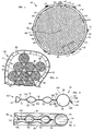
- Figure 1 is a top plan view of a preferred embodiment of the solar pool heater 10 of the invention
- Figure 2 is an enlarged cross section taken on line 2-2 of Figure 1
- Figure 3 is an enlarged sectional view taken on line 3-3 of Figure 1
- Figure 4 is a top plan view of a plurality of solar pool heaters 10 of Figure 1 in use floating on water 95 in a swimming pool 90.
- Heater 10 is soft and flexible so as to present no hazard should a person fall onto one either in pool 90 or outside of pool 90.
- Heater 10 generally comprises an outer ring 20 and central portion 50.
- the heater 10 is primarily constructed of upper film 14, such as upper film 14R of ring 20 and upper film 14C of central portion 50, and lower film 16, such as lower film 16R of ring 20 and lower film 16C of central portion 50.
- the film may be of thin plastic, such as of vinyl, bonded, such as by radio frequency bonding, at bonds 18 so as to form the general structure.
- Outer ring 20 includes upper film 14R and lower film 16R bonded at bonds 18R to define a chamber 22 that is inflatable or turgesible with a fluid, such as a gas, such as air, or a liquid, such as water, such as pool water, through a valve, such as valve 23.
- Valve 23 may be any conventional valve, such as a bore and a stopper, which can control ingress and egress of fluid to and from chamber 22.
- Outer ring 20 includes a radially outward side 30, a radially inward side 34, a top 36, and a bottom 38. Top 36 and bottom 38 of ring 20 generally define spaced parallel planes.
- Central portion 50 is disposed centrally of outer ring 20 and includes an upper film 14C, and a lower film 16C joined, such as around its periphery 59, to upper film 14C to define a cavity 52 therebetween for holding gas. Cavity 52 has an area in top view. Periphery 59 of central portion 50 is connected to ring 20, such as to radially inward side 34. Inflation and deflation means, such as valve 53, controls ingress and egress of gas, such as air, with cavity 52. When cavity 52 is inflated with air, heater 10 will float on water 95.
- central portion 50 contains a single inflatable cavity 52 to facilitate inflation and deflation.
- a plurality of spot welds 60 connect upper film 14C and lower film 16C central of periphery 59 such that upper film 14C and lower film 16C of cavity 52 are held in proximity and held, as seen in Figure 3 , within the planes defined by the top 36 and bottom 38 of ring 20, when chamber 22 and cavity 52 are inflated with air and heater 10 is placed on the ground. This ensures: that heater 10 lies properly on water 95; that films 14C, 16C are held in close proximity for superior solar heating properties; and that heaters 10 are stackable when inflated. Close spacing of films 14C, 16C decreases heat loss from convection. Welds allow the use of just two films and spot welds 60 provide the most area for cavity 52 while still holding films 14C, 16C in close proximity.
- Spot welds 60 are disposed in a grid so as to shape upper film 14C into an array of convex surfaces; a convex surface being located between each four welds 60. Each convex surface acts as a lens for intensifying the solar heating effect on lower film 16C.
- Chamber 22 and cavity 52 are inflatable and deflatable independently of each other.
- Central portion 50 includes air escape means, such as a plurality of passages, such as through-holes 65 near periphery 59 and in the center of central portion 50, for allowing air to escape from below central portion 50 when heater 10 is deployed on water 95 and for allowing water on the top of central portion 50, such as from rain or from a decorative water fall, to drain. Holes 65 may be evenly spaced, such as every sixty degrees around the circumference of heater 10. Upon deployment, entrapped air under central portion 50 substantially escapes upward through holes 65 such that the center of central portion 50 sags slightly and central portion 50 is substantially in contact with water 95. Because of the flexibility of heater 10, at proper inflation, heater 10 will conform to waves in pool 90 so as to keep new air from entering under central portion.
- air escape means such as a plurality of passages, such as through-holes 65 near periphery 59 and in the center of central portion 50, for allowing air to escape from below central portion 50 when heater 10 is deployed on water 95 and for allowing water on the top of central
- Magnetic means such as a plurality of spaced magnets 40, are connected to radially outward side 30 of ring 20, for conditioning water 95 and for releasably joining to magnetic means of other heaters 10 to join a plurality of heaters 10 to form a raft 11, as seen in Figure 4 .
- Magnets 40 may be uniformly spaced, such as every sixty degrees. When heater 10 is floating, magnet 40 is in contact with water 95 and produces a magnetic field in water 95 for conditioning water 95. Magnets 40 may be bonded between upper and lower film 14, 16. Magnets 40 of floating heaters 10 tend to attach to magnets 40 of other similar floating heaters 10 to form rafts 11.
- Rafts 11 facilitate removable of heaters 10 from pool 90, because when one heater 10 near pool side 92 is grasped the other heaters 10 in its raft 11 will also be pulled to pool side 92 as the grasped heater 10 is pulled out. Floating heaters 10 in a raft 11 are easily separated by a person in pool 90 such that a person falling into pool 95 is not trapped under raft 11. Heaters 10 may help float a person who accidentally falls into pool 90.
- Heater 10 includes hanging means, such as hanger 45 attached to radially outward side 30 of ring 20, for hanging heater 10, such as on a peg on a wall, during storage.
- Hanger 45 may be constructed of bonded upper and lower film 14, 16 having a bore therethrough.
- chamber 22 of outer ring 20 and cavity 52 of central portion 50 are made from just two films, upper film 14 and lower film 16 welded together.
- Vinyl is the preferred film, but other films could be used.
- upper film 14 has high transmissivity of sunlight so light easily enters chamber 22 and cavity 52.
- Upper film 14 may be clear plastic, such as 0.1524mm (0.006") thick vinyl.
- lower film 16 has high absorptivity of sunlight and is stronger, for puncture resistance.
- Lower film 16 may be 0.2032mm (0.008”) thick vinyl of dark color, such as blue.
- films 14, 16 are resistant to breakdown from ultraviolet light.
- Upper film 14 may be modified in manners known in the art which cause it to reflect downwardly much of the infrared energy impinging on its underside, thereby contributing to a "greenhouse” effect. Such reflectivity may be achieved by the use of films and coatings which provide unidirectional reflectivity. These films and coatings are well known in the art and are commonly applied to the windows of buildings to deter the entry of solar energy without preventing outward visibility. Mechanical, physical, molecular or chemical modifications of the film may also provide the appropriate reflectivity.
- Lower film 16 is preferably opaque, absorptive of solar energy and of relatively high thermal conductivity.
- Lower film 16 may be provided with a material which will enhance its capability of absorbing solar energy to produce heat. Absorption-enhancing materials are well known and include carbon black, aluminum, copper and metal oxides.
- Lower film 16 may be modified so that the heat generated by the incident solar energy will be transmitted readily through the thickness.
- a liquid, powder or film may be laminated to the surface of lower film 16, and/or metallic particles may be added to lower film 16 to increase its thermal conductivity. Coatings and mixtures of powdered metals and inetal oxides, as well as threads, filaments, filings and compounds placed on and/or located within lower film 16 may improve its thermal conductivity.
- lower film 16 has a density for light absorption of about fifty percent such that about fifty percent of the light energy heats the surface and about fifty percent passes through for deep water heating. This can be varied for specific use.
- a typical outside diameter for heater 10 is 152.4cm (sixty inches), although other diameters could be used to better accommodate pools of various size and shape.
- the small amount of open water 96 between heaters 10 is desirable as a small amount of direct sunlight is necessary to prevent growth of undesirable alga such as mustard algae.
- outer ring 20 is filled with water, or is at least partially filled depending on the wind conditions, using valve 23. The weight of the water in outer ring 20 holds heater 10 within pool.
- heaters 10 may be stacked or may be hung by hangers 45.
- heaters 10 may be deflated by expelling air and water from chamber 22 and cavity 52 out valves 23, 53 respectively.
- Heater 10 is specifically designed for deflation by rolling from the edge opposite valves 23, 53.
- the present invention provides an extremely simple, efficient, reliable, and passive floating solar pool heater which heats the pool during sunlight and reduces heat loss at other times.
- heater 10 is shown as circular in top view, it could have other shapes. Therefore, it is to be understood that all matter herein is to be interpreted as illustrative and not in any limiting sense, and it is intended to cover in the appended claims such modifications as come within the scope of the claimed invention.
Landscapes
- Engineering & Computer Science (AREA)
- Chemical & Material Sciences (AREA)
- Mechanical Engineering (AREA)
- Sustainable Development (AREA)
- Sustainable Energy (AREA)
- Thermal Sciences (AREA)
- Physics & Mathematics (AREA)
- Combustion & Propulsion (AREA)
- Life Sciences & Earth Sciences (AREA)
- General Engineering & Computer Science (AREA)
- Tents Or Canopies (AREA)
- Heat-Pump Type And Storage Water Heaters (AREA)
- Thermal Insulation (AREA)
- Heat Treatment Of Water, Waste Water Or Sewage (AREA)
- Special Spraying Apparatus (AREA)
Description
- It is desirable to cover pools, such as swimming pools, for various reasons, such as preventing evaporation and heat loss, and providing solar heating. Conventional pool covers have several shortcomings. Heavy covers are expensive. They are large and bulky and not easily used or stored. Pool covers of light material, such as of bubble pack type, typically cover an entire pool and project over the decking for anchoring the cover and preventing the cover from falling into the pool. Such covers are subject to winds that often lift them so as to dislocate or actually move the covers from the pool areas to other areas, e.g. neighbor's yard. Winds can pull such large light pool covers from under sand bags, and/or steel pipes as are commonly used. Further, any large cover can be dangerous for small children or animals, which can be trapped underneath.
- Smaller solar pool heaters of the floating type have been proposed, but none appear to be marketed. The ones proposed have several disadvantages. Many have hard or rigid parts that are dangerous should a person fall into the pool and that make them bulky and difficult to store. Some of the larger ones have large air chambers that would encourage convection and heat loss. The lighter ones would tend to fly away in the wind. In general, they are bulky to store, difficult to deploy, and difficult to retrieve and remove.
-
US 4,022,187 discloses a floating solar heater for swimming pools which comprises a number a separate floating units. The units may be circular or triangular in shape and comprise a translucent upper panel spaced from an opaque lower panel. The upper and lower panels are joined about their peripheral edges to define an ambient air filled chamber. -
US 4,033,326 discloses an inflatable solar collector for heating a swimming pool. The solar collector is formed from a number of individual sections joined by tab. Each section has a transparent or translucent upper portion and a lower portion having an inner surface capable of absorbing solar energy from solar rays that penetrate the upper portion. - Therefore, there it is desirable to have an improved floating pool heater that overcomes shortcomings in the prior art.
EP 0 152 536 discloses an inflatable toy comprising an outer ring and a central portion. - Magnets and magnetic fields have been known to treat water. Examples of magnetic treatment devices are disclosed in
U.S. Pat. Nos. 3,951,807 and4,153,559 in the name of Charles H. Sanderson andU.S. Patent 5,059,296 to Mark Sherman . The magnet is said to condition the water by altering various minerals suspended in the water and to reduce the amount of oxidizer, such as chlorine, required. - Therefore, it is further desirable that the improved floating pool heater incorporate magnets for conditioning the water.
- In accordance with a first aspect of the invention, there is provided a solar pool heater as defined in claim 1. Further optional features of the first aspect of the invention are set out in the claims dependent on claim 1.
- When chamber and cavity are inflated, the cavity is within the top and bottom planes of the ring. Because the chamber and the cavity are independently inflatable, the ring can be inflated with water for holding the heater in a pool in winds.
- Holes through the central portion permit egress of air from under the central portion when the heater is placed on water such that the lower film rests substantially on the water.
- Valves for chamber and cavity are located near one edge such that the heater may be deflated by rolling from an edge opposite the valves.
- Magnets on the ring condition water and attach to similar floating heaters to form rafts.
- A second aspect of the invention resides in use of the apparatus of the first aspect to passively heat a body of water in a pool as defined in
claim 11. - The features and advantages of the invention will be readily understood when the detailed description thereof is read in conjunction with the drawings wherein like reference numerals refer to like parts throughout.
-
-
Figure 1 is a top plan view of a preferred embodiment of the solar pool heater of the invention. -
Figure 2 is an enlarged cross section taken on line 2-2 ofFigure 1 . -
Figure 3 is an enlarged sectional view taken on line 3-3 ofFigure 1 . -
Figure 4 is a top plan view of a plurality of solar pool heaters ofFigure 1 in use in a swimming pool. - With reference now to the drawings,
Figure 1 is a top plan view of a preferred embodiment of thesolar pool heater 10 of the invention,Figure 2 is an enlarged cross section taken on line 2-2 ofFigure 1, Figure 3 is an enlarged sectional view taken on line 3-3 ofFigure 1, and Figure 4 is a top plan view of a plurality ofsolar pool heaters 10 ofFigure 1 in use floating onwater 95 in aswimming pool 90. -
Heater 10 is soft and flexible so as to present no hazard should a person fall onto one either inpool 90 or outside ofpool 90.Heater 10 generally comprises anouter ring 20 andcentral portion 50. In accordance with the invention theheater 10 is primarily constructed ofupper film 14, such asupper film 14R ofring 20 andupper film 14C ofcentral portion 50, andlower film 16, such aslower film 16R ofring 20 andlower film 16C ofcentral portion 50. The film may be of thin plastic, such as of vinyl, bonded, such as by radio frequency bonding, atbonds 18 so as to form the general structure. -
Outer ring 20 includesupper film 14R andlower film 16R bonded atbonds 18R to define achamber 22 that is inflatable or turgesible with a fluid, such as a gas, such as air, or a liquid, such as water, such as pool water, through a valve, such asvalve 23. Valve 23 may be any conventional valve, such as a bore and a stopper, which can control ingress and egress of fluid to and fromchamber 22.Outer ring 20 includes a radiallyoutward side 30, a radiallyinward side 34, atop 36, and abottom 38. Top 36 andbottom 38 ofring 20 generally define spaced parallel planes. -
Central portion 50 is disposed centrally ofouter ring 20 and includes anupper film 14C, and alower film 16C joined, such as around itsperiphery 59, toupper film 14C to define acavity 52 therebetween for holding gas.Cavity 52 has an area in top view.Periphery 59 ofcentral portion 50 is connected toring 20, such as to radiallyinward side 34. Inflation and deflation means, such asvalve 53, controls ingress and egress of gas, such as air, withcavity 52. Whencavity 52 is inflated with air,heater 10 will float onwater 95. Preferably,central portion 50 contains a singleinflatable cavity 52 to facilitate inflation and deflation. - A plurality of
spot welds 60, connectupper film 14C andlower film 16C central ofperiphery 59 such thatupper film 14C andlower film 16C ofcavity 52 are held in proximity and held, as seen inFigure 3 , within the planes defined by thetop 36 andbottom 38 ofring 20, whenchamber 22 andcavity 52 are inflated with air andheater 10 is placed on the ground. This ensures: thatheater 10 lies properly onwater 95; thatfilms heaters 10 are stackable when inflated. Close spacing offilms spot welds 60 provide the most area forcavity 52 while still holdingfilms Spot welds 60 are disposed in a grid so as to shapeupper film 14C into an array of convex surfaces; a convex surface being located between each fourwelds 60. Each convex surface acts as a lens for intensifying the solar heating effect onlower film 16C.Chamber 22 andcavity 52 are inflatable and deflatable independently of each other. -
Central portion 50 includes air escape means, such as a plurality of passages, such as through-holes 65 nearperiphery 59 and in the center ofcentral portion 50, for allowing air to escape from belowcentral portion 50 whenheater 10 is deployed onwater 95 and for allowing water on the top ofcentral portion 50, such as from rain or from a decorative water fall, to drain.Holes 65 may be evenly spaced, such as every sixty degrees around the circumference ofheater 10. Upon deployment, entrapped air undercentral portion 50 substantially escapes upward throughholes 65 such that the center ofcentral portion 50 sags slightly andcentral portion 50 is substantially in contact withwater 95. Because of the flexibility ofheater 10, at proper inflation,heater 10 will conform to waves inpool 90 so as to keep new air from entering under central portion. - Magnetic means, such as a plurality of spaced
magnets 40, are connected to radiallyoutward side 30 ofring 20, forconditioning water 95 and for releasably joining to magnetic means ofother heaters 10 to join a plurality ofheaters 10 to form araft 11, as seen inFigure 4 .Magnets 40 may be uniformly spaced, such as every sixty degrees. Whenheater 10 is floating,magnet 40 is in contact withwater 95 and produces a magnetic field inwater 95 forconditioning water 95.Magnets 40 may be bonded between upper andlower film Magnets 40 of floatingheaters 10 tend to attach tomagnets 40 of other similar floatingheaters 10 to form rafts 11.Rafts 11 facilitate removable ofheaters 10 frompool 90, because when oneheater 10 nearpool side 92 is grasped theother heaters 10 in itsraft 11 will also be pulled to poolside 92 as the graspedheater 10 is pulled out. Floatingheaters 10 in araft 11 are easily separated by a person inpool 90 such that a person falling intopool 95 is not trapped underraft 11.Heaters 10 may help float a person who accidentally falls intopool 90. -
Heater 10 includes hanging means, such ashanger 45 attached to radiallyoutward side 30 ofring 20, for hangingheater 10, such as on a peg on a wall, during storage.Hanger 45 may be constructed of bonded upper andlower film - As described above,
chamber 22 ofouter ring 20 andcavity 52 ofcentral portion 50 are made from just two films,upper film 14 andlower film 16 welded together. Vinyl is the preferred film, but other films could be used. Preferably,upper film 14 has high transmissivity of sunlight so light easily enterschamber 22 andcavity 52.Upper film 14 may be clear plastic, such as 0.1524mm (0.006") thick vinyl. Preferably,lower film 16 has high absorptivity of sunlight and is stronger, for puncture resistance.Lower film 16 may be 0.2032mm (0.008") thick vinyl of dark color, such as blue. Preferably,films -
Upper film 14 may be modified in manners known in the art which cause it to reflect downwardly much of the infrared energy impinging on its underside, thereby contributing to a "greenhouse" effect. Such reflectivity may be achieved by the use of films and coatings which provide unidirectional reflectivity. These films and coatings are well known in the art and are commonly applied to the windows of buildings to deter the entry of solar energy without preventing outward visibility. Mechanical, physical, molecular or chemical modifications of the film may also provide the appropriate reflectivity. -
Lower film 16 is preferably opaque, absorptive of solar energy and of relatively high thermal conductivity.Lower film 16 may be provided with a material which will enhance its capability of absorbing solar energy to produce heat. Absorption-enhancing materials are well known and include carbon black, aluminum, copper and metal oxides.Lower film 16 may be modified so that the heat generated by the incident solar energy will be transmitted readily through the thickness. A liquid, powder or film may be laminated to the surface oflower film 16, and/or metallic particles may be added tolower film 16 to increase its thermal conductivity. Coatings and mixtures of powdered metals and inetal oxides, as well as threads, filaments, filings and compounds placed on and/or located withinlower film 16 may improve its thermal conductivity. Preferably,lower film 16 has a density for light absorption of about fifty percent such that about fifty percent of the light energy heats the surface and about fifty percent passes through for deep water heating. This can be varied for specific use. - A typical outside diameter for
heater 10 is 152.4cm (sixty inches), although other diameters could be used to better accommodate pools of various size and shape. The small amount ofopen water 96 betweenheaters 10 is desirable as a small amount of direct sunlight is necessary to prevent growth of undesirable alga such as mustard algae. - To prevent
heater 10 from blowing away in high wind,outer ring 20 is filled with water, or is at least partially filled depending on the wind conditions, usingvalve 23. The weight of the water inouter ring 20 holdsheater 10 within pool. - For temporary storage of
heaters 10 during use ofpool 90,heaters 10 may be stacked or may be hung byhangers 45. For long term storage and shipping,heaters 10 may be deflated by expelling air and water fromchamber 22 andcavity 52 outvalves Heater 10 is specifically designed for deflation by rolling from the edge oppositevalves - From the foregoing description, it is seen that the present invention provides an extremely simple, efficient, reliable, and passive floating solar pool heater which heats the pool during sunlight and reduces heat loss at other times.
- Although a particular embodiment of the invention has been illustrated and described, various changes may be made in the form, composition, construction, and arrangement of the parts herein without sacrificing any of its advantages. For example, although
heater 10 is shown as circular in top view, it could have other shapes. Therefore, it is to be understood that all matter herein is to be interpreted as illustrative and not in any limiting sense, and it is intended to cover in the appended claims such modifications as come within the scope of the claimed invention.
Claims (11)
- A solar pool heater (10) comprising an inflatable outer ring (20) defining a chamber (22) for holding fluid; said ring including:a radially outward side (30);a radially inward side (34);a top (36);a bottom (38);the heater also comprising a central portion (50) disposed centrally within said ring, the central portion including an upper film (14) and a lower film (16) joined to said upper film to define a cavity (52) therebetween for holding gas;wherein a periphery (59) of the central portion is connected to said outer ring (20);wherein said chamber (22) and said cavity (52) are independently inflatable, the outer ring (20) having a valve (23) for controlling ingress and egress of fluid with said chamber (22) and the central portion (50) having a valve (53) for controlling ingress and egress of gas with said cavity (52); said cavity when inflated with gas for floating said heater on water such that said heater floats on said liquid; the upper and lower films (14, 16) completely form the entirety of both the chamber (22) and the cavity (52), the lower film (16) being joined to the upper film (14) by a plurality of spot welds (60) disposed in a grid, and;said top (36) of said ring (20) defines a top plane and said bottom (38) of said ring (20) defines a bottom plane and wherein when the chamber (22) and the cavity (52) are inflated, said cavity (52) is entirely within the top and bottom planes.
- The heater (10) of claim 1 comprising magnetic means (40) on said ring (20) for magnetic attachment to a similar floating heater.
- The heater (10) of any preceding claim comprising magnetic means (40) on said ring (20) adapted for contact with the water when said heater is floating for conditioning the water.
- The heater (10) of any preceding claim comprising air escape means (65) through said central portion (50) for egress of air from under said central portion when said heater is placed on water such that said lower film (16) rests substantially on the water.
- The heater (10) of any preceding claim wherein said valves (23, 53) being located near one edge; said heater adapted for deflation by rolling from an edge opposite said valves.
- The heater (10) of any preceding claim wherein the upper film (14) comprises a clear plastic.
- The heater (10) of any preceding claim wherein the lower film (16) comprises an opaque plastic.
- The heater (10) of claim 4 wherein the air-escape means (65) comprises through-holes (65) disposed through said central portion (50).
- The heater (10) of claim 1 wherein the periphery (59) of the central portion (50) is connected to a radially inward side (34) of the ring (20) at a position which is substantially centred between the top and bottom planes.
- A plurality of heaters (10) as defined in any preceding claim wherein said heaters are attached to one another with magnetic means (40).
- Use of the apparatus (10) as claimed in any one of claims 1 to 10 to passively heat a body of water in a pool.
Applications Claiming Priority (2)
| Application Number | Priority Date | Filing Date | Title |
|---|---|---|---|
| US875933 | 1992-04-29 | ||
| US10/875,933 US7093593B2 (en) | 2004-06-24 | 2004-06-24 | Floating solar pool heater |
Publications (3)
| Publication Number | Publication Date |
|---|---|
| EP1610072A2 EP1610072A2 (en) | 2005-12-28 |
| EP1610072A3 EP1610072A3 (en) | 2011-08-31 |
| EP1610072B1 true EP1610072B1 (en) | 2016-05-25 |
Family
ID=34701539
Family Applications (1)
| Application Number | Title | Priority Date | Filing Date |
|---|---|---|---|
| EP05252799.1A Active EP1610072B1 (en) | 2004-06-24 | 2005-05-06 | Floating solar pool heater |
Country Status (7)
| Country | Link |
|---|---|
| US (3) | US7093593B2 (en) |
| EP (1) | EP1610072B1 (en) |
| AR (1) | AR051175A1 (en) |
| AU (2) | AU2004208725A1 (en) |
| BR (1) | BRPI0501524A (en) |
| CA (1) | CA2505210C (en) |
| ZA (1) | ZA200407050B (en) |
Families Citing this family (18)
| Publication number | Priority date | Publication date | Assignee | Title |
|---|---|---|---|---|
| US8342167B2 (en) * | 2004-06-24 | 2013-01-01 | Rosene Richard C | Floating solar heater with stabilizing band |
| US7093593B2 (en) * | 2004-06-24 | 2006-08-22 | Rosene Richard C | Floating solar pool heater |
| US8635999B2 (en) * | 2006-04-07 | 2014-01-28 | Richard C Rosene | Floating spa cover or adjustable size |
| US20080317551A1 (en) * | 2007-06-21 | 2008-12-25 | Phillip John Bennett | Evaporation retarding cover |
| CA2639348C (en) * | 2007-09-20 | 2010-08-10 | Geomembrane Technologies Inc. | Movable agricultural reservoir cover with hatch, and a method for liquefying a content of an agricultural reservoir |
| US8096294B1 (en) | 2008-10-08 | 2012-01-17 | Jenkins Richard D | Spa water heating apparatus and method |
| US8480900B2 (en) * | 2009-04-27 | 2013-07-09 | Joseph P. Santamaria | Buoyant water heating device |
| US8683620B1 (en) | 2009-04-29 | 2014-04-01 | John F. Krumme | Pool covers |
| US20120304372A1 (en) | 2011-06-03 | 2012-12-06 | Poseidon Concepts Partnership Limited | Container cover |
| US20140053331A1 (en) * | 2012-02-08 | 2014-02-27 | Cade A. Andersen | Bathtub floating thermal insulators |
| US9353540B2 (en) * | 2012-07-17 | 2016-05-31 | Joseph Jennings | Swimming pool pillow |
| USD733322S1 (en) | 2014-04-15 | 2015-06-30 | Robert Walczak | Hexagonally-shaped solar heating swimming pool cover |
| US20160362903A1 (en) * | 2015-06-15 | 2016-12-15 | Rodney Overstreet | Wind-resistant cover |
| AT517997A1 (en) * | 2015-08-21 | 2017-06-15 | Guger Forschungs Gmbh | photovoltaic module |
| US10807685B2 (en) * | 2015-09-23 | 2020-10-20 | Solarpods, Inc. | Self assembling floating solar pods |
| CN206016342U (en) * | 2016-08-31 | 2017-03-15 | 明达实业(厦门)有限公司 | A kind of pond thermal insulation cover, insulation plunger and insulation enclosing cover |
| US10476427B2 (en) | 2017-05-03 | 2019-11-12 | Sunpower Corporation | Photovoltaic modules |
| US11072936B2 (en) | 2018-07-18 | 2021-07-27 | Patrick GEORGOFF | Baby and kiddie pool sunless water heater with circulating pump |
Citations (1)
| Publication number | Priority date | Publication date | Assignee | Title |
|---|---|---|---|---|
| EP0152536A2 (en) * | 1984-02-13 | 1985-08-28 | John GmbH | Inflatable toy |
Family Cites Families (71)
| Publication number | Priority date | Publication date | Assignee | Title |
|---|---|---|---|---|
| US2888717A (en) * | 1954-06-28 | 1959-06-02 | Domitrovic William | Silo sealing cover |
| GB839716A (en) * | 1957-11-13 | 1960-06-29 | Frankenstein & Sons Manchester | Improvements in or relating to inflatable life-rafts |
| US3072920A (en) * | 1959-07-23 | 1963-01-15 | John I Yellott | Swimming pool cover for collection or reflection of solar heat |
| US3600721A (en) * | 1967-09-01 | 1971-08-24 | Eugene H Pusey | Swimming pool cover |
| US3608099A (en) * | 1969-10-20 | 1971-09-28 | Domain Ind Inc | Swimming pool cover |
| US3803651A (en) * | 1970-03-30 | 1974-04-16 | A Moore | Tubular buoy |
| US3670349A (en) * | 1970-03-30 | 1972-06-20 | Alvin E Moore | Light weight article |
| US3683428A (en) * | 1970-06-01 | 1972-08-15 | Lester Morris | Rigid, buoyant, insulating and rapid folding swimming pool covers |
| US3798690A (en) * | 1972-02-11 | 1974-03-26 | A Moore | Light-weight, inflated-structure boat |
| US3893443A (en) | 1973-01-11 | 1975-07-08 | Richard H Smith | Floating solar pool heater |
| US4601072A (en) | 1973-06-05 | 1986-07-22 | Aine Harry E | Swimming pool cover |
| US3951807A (en) | 1973-09-20 | 1976-04-20 | Sanderson Charles H | Water conditioning apparatus |
| US3872522A (en) * | 1973-11-12 | 1975-03-25 | Robert Br Bennett | Protective cover for pools |
| US3949095A (en) | 1974-07-10 | 1976-04-06 | Michael Pelehach | Solar energy pool heating apparatus |
| US3940809A (en) * | 1974-08-26 | 1976-03-02 | The Raymond Lee Organization, Inc. | Swimming pool cover |
| US4028750A (en) * | 1974-12-05 | 1977-06-14 | Barracudaverken Aktiebolag | Cover for water-filled outdoor swimming pools |
| US3984881A (en) | 1974-12-19 | 1976-10-12 | Catel Manufacturing Inc. | Solar panel |
| US3984882A (en) | 1975-08-25 | 1976-10-12 | Catel Manufacturing Inc. | Panel structure for use on water bodies |
| US4000527A (en) * | 1975-08-26 | 1977-01-04 | Vinyl-Fab Industries, Inc. | Swimming pool cover floating support |
| US4109325A (en) * | 1975-09-12 | 1978-08-29 | Shuff Gregory Douglas | Inflatable swimming pool cover system |
| US4022187A (en) | 1975-11-24 | 1977-05-10 | Roberts Marvin A | Floating solar heater for swimming pools |
| US4060070A (en) * | 1976-01-22 | 1977-11-29 | Solar Industries, Inc. | Solar heating |
| US4270232A (en) * | 1976-02-10 | 1981-06-02 | Ballew Ray D | Thermal pool cover |
| US4033326A (en) * | 1976-02-23 | 1977-07-05 | Leitner Lionel J | Inflatable solar collector for swimming pool |
| US4153559A (en) | 1977-05-20 | 1979-05-08 | Sanderson Charles H | Water treatment device and method for manufacturing same |
| US4146015A (en) | 1977-09-09 | 1979-03-27 | Engineering & Research Associates, Inc. | Solar pool heater |
| US4222366A (en) | 1978-07-21 | 1980-09-16 | Engineering & Research Associates, Inc. | Solar pool heater |
| CA1127922A (en) | 1978-09-01 | 1982-07-20 | Gerald E. Wilson | Solar heating device |
| US4313421A (en) | 1978-09-06 | 1982-02-02 | Vulcan Australia Limited | Solar heating apparatus for swimming pools |
| US4332048A (en) * | 1980-03-03 | 1982-06-01 | Eddy Roger C | Lockable support float |
| US4236259A (en) * | 1980-03-03 | 1980-12-02 | Wendy S. Crane | Spa cover |
| US4284060A (en) | 1980-06-18 | 1981-08-18 | Philadelphia Rivet Company | Floating solar pool heater |
| US4366806A (en) * | 1980-08-18 | 1983-01-04 | Engineering & Research Assocs., Inc. | Solar pool heater |
| US4320003A (en) | 1981-01-09 | 1982-03-16 | Kemtune, Inc. | Bypass water conditioner |
| US4471759A (en) * | 1981-04-28 | 1984-09-18 | B. Shawn Buckley | Method of forming a solar collector or hot water storage tank and solar water heating apparatus using same |
| FR2539493A1 (en) * | 1983-01-14 | 1984-07-20 | Degrolard Raymond | Inflatable solar collector |
| US4749606A (en) * | 1985-11-21 | 1988-06-07 | Plastic Techniques, Inc. | Floatable pad |
| US5059296A (en) | 1989-02-21 | 1991-10-22 | Floatron, Inc. | Portable self-contained solar powered water purifier |
| US4976642A (en) * | 1989-09-15 | 1990-12-11 | Wilkie Lawrence A | Life ring |
| DE4001719A1 (en) * | 1990-01-22 | 1991-07-25 | Guenter Dudek | Solar heater for paddling pool - has round black base surface with raised inflatable tubular rim and central weight |
| US5095557A (en) * | 1990-10-29 | 1992-03-17 | Ken Keyes | Pool cover assembly |
| US5144704A (en) * | 1990-11-01 | 1992-09-08 | Genzel Charles C J | Swimming pool cover with multiple air compartments |
| US5216762A (en) * | 1991-11-25 | 1993-06-08 | Denny Thomas P | Floating pool cover apparatus |
| US6385791B1 (en) | 1994-01-12 | 2002-05-14 | Harry Bussey, Jr. | Pool cover |
| US5347984A (en) * | 1994-02-19 | 1994-09-20 | Klaren Johannes A | Solar pool heater |
| US5394571A (en) * | 1994-09-01 | 1995-03-07 | Vernon; Susan N. | Inflatable bedpan with disposable liner |
| US5546615A (en) * | 1994-11-14 | 1996-08-20 | Waste Management & Design, Inc. | Method and device for providing an insulated cover over a pool |
| US5511536A (en) * | 1995-03-23 | 1996-04-30 | Cpi Packaging, Inc. | Solar-type pool cover |
| US5679040A (en) * | 1995-07-18 | 1997-10-21 | Roger Davis | Apparatus and method for supporting a user |
| US5667416A (en) * | 1996-01-31 | 1997-09-16 | Barth; Terry D. | Flotation device and swimming aid |
| US5779512A (en) * | 1996-02-15 | 1998-07-14 | Rupert; Roger J. | Flotation device |
| US6076201A (en) * | 1997-02-20 | 2000-06-20 | Sportsstuff, Inc. | Protective cover for inflatable swimming pools |
| US5938900A (en) | 1997-12-10 | 1999-08-17 | Reynolds; Sam C. | Method and apparatus for treating water |
| US6047415A (en) * | 1998-08-10 | 2000-04-11 | Brown; Ruth A. | Pool cover |
| US6171490B1 (en) | 1999-02-26 | 2001-01-09 | Kil Ho Kim | Water purifier with a rotating magnet |
| US6185765B1 (en) * | 1999-06-22 | 2001-02-13 | Lois A. High | Inflatable beach pillow system with an attachable blanket |
| US6286156B1 (en) * | 1999-09-21 | 2001-09-11 | Thelma Sullivan | Mesh screen swimming pool cover |
| US6220908B1 (en) * | 1999-12-10 | 2001-04-24 | Sportsstuff, Inc. | Inflatable towable vehicle |
| US20010047539A1 (en) * | 2000-03-16 | 2001-12-06 | Lynn John M | Method and apparatus to either heat or cool a pool |
| US6280271B1 (en) * | 2000-05-18 | 2001-08-28 | Sportsstuff, Inc. | Inflatable shaded float |
| US6408453B1 (en) * | 2001-05-25 | 2002-06-25 | Aqua-Marine International Inc. | Inflatable swimming pool assembly |
| US6539559B1 (en) * | 2001-11-03 | 2003-04-01 | Cathy L. Creech | Anti-litter float for a swimming pool and method of using anti-litter float for a swimming pool |
| US6523190B1 (en) * | 2002-01-29 | 2003-02-25 | Cantar/Polyair Corporation | Heat retaining swimming pool cover |
| US6571789B1 (en) * | 2002-10-28 | 2003-06-03 | Paul C. Pickert | High efficiency swimming pool or commercial liquid tank insulation device |
| US20050022297A1 (en) * | 2003-07-31 | 2005-02-03 | Furio Orologio | Solar heat reflective pool covering |
| US7093593B2 (en) * | 2004-06-24 | 2006-08-22 | Rosene Richard C | Floating solar pool heater |
| US20060195978A1 (en) * | 2005-03-07 | 2006-09-07 | Stout Products, Llc | Protective spa cover and method |
| US8635999B2 (en) * | 2006-04-07 | 2014-01-28 | Richard C Rosene | Floating spa cover or adjustable size |
| USD579570S1 (en) * | 2006-04-07 | 2008-10-28 | Rosene Richard C | Floating spa cover |
| US20070271692A1 (en) * | 2006-05-26 | 2007-11-29 | Donald William Herd | Worry-free inflatable cover |
| US20070199142A1 (en) * | 2007-05-17 | 2007-08-30 | Patrick Gray | Pool or spa cover and methods therefor |
-
2004
- 2004-06-24 US US10/875,933 patent/US7093593B2/en active Active
- 2004-09-03 ZA ZA200407050A patent/ZA200407050B/en unknown
- 2004-09-07 AU AU2004208725A patent/AU2004208725A1/en not_active Abandoned
-
2005
- 2005-04-25 BR BRPI0501524-3A patent/BRPI0501524A/en not_active IP Right Cessation
- 2005-04-26 CA CA002505210A patent/CA2505210C/en not_active Expired - Fee Related
- 2005-05-06 EP EP05252799.1A patent/EP1610072B1/en active Active
- 2005-06-13 AR ARP050102387A patent/AR051175A1/en not_active Application Discontinuation
-
2006
- 2006-04-07 US US11/400,268 patent/US7603727B2/en active Active
- 2006-08-22 US US11/507,918 patent/US8347876B2/en active Active
-
2009
- 2009-11-15 AU AU2009238265A patent/AU2009238265B2/en not_active Ceased
Patent Citations (1)
| Publication number | Priority date | Publication date | Assignee | Title |
|---|---|---|---|---|
| EP0152536A2 (en) * | 1984-02-13 | 1985-08-28 | John GmbH | Inflatable toy |
Also Published As
| Publication number | Publication date |
|---|---|
| US8347876B2 (en) | 2013-01-08 |
| US20060005830A1 (en) | 2006-01-12 |
| US20060180142A1 (en) | 2006-08-17 |
| CA2505210A1 (en) | 2005-12-24 |
| BRPI0501524A (en) | 2006-09-05 |
| US7093593B2 (en) | 2006-08-22 |
| AU2009238265A1 (en) | 2009-12-03 |
| AR051175A1 (en) | 2006-12-27 |
| EP1610072A2 (en) | 2005-12-28 |
| EP1610072A3 (en) | 2011-08-31 |
| US20060283443A1 (en) | 2006-12-21 |
| ZA200407050B (en) | 2005-05-25 |
| AU2009238265B2 (en) | 2011-06-16 |
| US7603727B2 (en) | 2009-10-20 |
| CA2505210C (en) | 2010-01-12 |
| AU2004208725A1 (en) | 2006-01-12 |
Similar Documents
| Publication | Publication Date | Title |
|---|---|---|
| EP1610072B1 (en) | Floating solar pool heater | |
| US5555877A (en) | Cover for pond used to collect solar radiation | |
| US10739037B2 (en) | Floating solar pool heater | |
| US5987661A (en) | Inflatable swimming pool and supporting net | |
| US4953239A (en) | Inflatable pool cover | |
| US4146015A (en) | Solar pool heater | |
| IL180408A (en) | Water storage evaporation control | |
| US8099804B2 (en) | Thermally insulating blanket constructed of individual floats and system for deploying and retrieving same | |
| US11946280B2 (en) | Systems and methods for a container with portholes | |
| US20100028082A1 (en) | Barrier system for a body of fluid and method of forming the same | |
| US20060021125A1 (en) | Swimming pool having adjustable sunshade | |
| US4033326A (en) | Inflatable solar collector for swimming pool | |
| US4706307A (en) | Floating pool assembly | |
| WO2005108299A1 (en) | A floating cover system for a body of liquid | |
| US20100282240A1 (en) | Multi-mode, eco-friendly swimming pool heater system | |
| US3128478A (en) | Buoyant net and safety cover for swimming pools | |
| US9506261B2 (en) | Pool covers | |
| US20030046755A1 (en) | Floating bug, sun and privacy dome | |
| US3323795A (en) | Swim-through loop | |
| AU2006100736A4 (en) | A cover for a body of water | |
| US6640353B1 (en) | Solar pool heating system | |
| AU2004100619A4 (en) | A cover system for a body of liquid | |
| CN201935435U (en) | Solar pool heater and assembly | |
| WO2021100020A1 (en) | Solar blocker | |
| CN106422337B (en) | It travels in water bed |
Legal Events
| Date | Code | Title | Description |
|---|---|---|---|
| PUAI | Public reference made under article 153(3) epc to a published international application that has entered the european phase |
Free format text: ORIGINAL CODE: 0009012 |
|
| AK | Designated contracting states |
Kind code of ref document: A2 Designated state(s): AT BE BG CH CY CZ DE DK EE ES FI FR GB GR HU IE IS IT LI LT LU MC NL PL PT RO SE SI SK TR |
|
| AX | Request for extension of the european patent |
Extension state: AL BA HR LV MK YU |
|
| PUAL | Search report despatched |
Free format text: ORIGINAL CODE: 0009013 |
|
| AK | Designated contracting states |
Kind code of ref document: A3 Designated state(s): AT BE BG CH CY CZ DE DK EE ES FI FR GB GR HU IE IS IT LI LT LU MC NL PL PT RO SE SI SK TR |
|
| AX | Request for extension of the european patent |
Extension state: AL BA HR LV MK YU |
|
| RIC1 | Information provided on ipc code assigned before grant |
Ipc: F24J 2/04 20060101AFI20110726BHEP |
|
| 17P | Request for examination filed |
Effective date: 20120227 |
|
| AKX | Designation fees paid |
Designated state(s): AT BE BG CH CY CZ DE DK EE ES FI FR GB GR HU IE IS IT LI LT LU MC NL PL PT RO SE SI SK TR |
|
| 17Q | First examination report despatched |
Effective date: 20120720 |
|
| RAP1 | Party data changed (applicant data changed or rights of an application transferred) |
Owner name: ROSENE, RICHARD CHARLES Owner name: ROSENE, LORA JEANNINE |
|
| RIN1 | Information on inventor provided before grant (corrected) |
Inventor name: ROSENE, LORA JEANNINE Inventor name: ROSENE, RICHARD CHARLES |
|
| GRAP | Despatch of communication of intention to grant a patent |
Free format text: ORIGINAL CODE: EPIDOSNIGR1 |
|
| INTG | Intention to grant announced |
Effective date: 20151012 |
|
| GRAS | Grant fee paid |
Free format text: ORIGINAL CODE: EPIDOSNIGR3 |
|
| GRAA | (expected) grant |
Free format text: ORIGINAL CODE: 0009210 |
|
| AK | Designated contracting states |
Kind code of ref document: B1 Designated state(s): AT BE BG CH CY CZ DE DK EE ES FI FR GB GR HU IE IS IT LI LT LU MC NL PL PT RO SE SI SK TR |
|
| REG | Reference to a national code |
Ref country code: GB Ref legal event code: FG4D |
|
| REG | Reference to a national code |
Ref country code: CH Ref legal event code: EP |
|
| REG | Reference to a national code |
Ref country code: IE Ref legal event code: FG4D Ref country code: AT Ref legal event code: REF Ref document number: 802662 Country of ref document: AT Kind code of ref document: T Effective date: 20160615 |
|
| REG | Reference to a national code |
Ref country code: DE Ref legal event code: R096 Ref document number: 602005049410 Country of ref document: DE |
|
| REG | Reference to a national code |
Ref country code: LT Ref legal event code: MG4D |
|
| REG | Reference to a national code |
Ref country code: NL Ref legal event code: MP Effective date: 20160525 |
|
| PG25 | Lapsed in a contracting state [announced via postgrant information from national office to epo] |
Ref country code: FI Free format text: LAPSE BECAUSE OF FAILURE TO SUBMIT A TRANSLATION OF THE DESCRIPTION OR TO PAY THE FEE WITHIN THE PRESCRIBED TIME-LIMIT Effective date: 20160525 Ref country code: LT Free format text: LAPSE BECAUSE OF FAILURE TO SUBMIT A TRANSLATION OF THE DESCRIPTION OR TO PAY THE FEE WITHIN THE PRESCRIBED TIME-LIMIT Effective date: 20160525 Ref country code: NL Free format text: LAPSE BECAUSE OF FAILURE TO SUBMIT A TRANSLATION OF THE DESCRIPTION OR TO PAY THE FEE WITHIN THE PRESCRIBED TIME-LIMIT Effective date: 20160525 |
|
| REG | Reference to a national code |
Ref country code: AT Ref legal event code: MK05 Ref document number: 802662 Country of ref document: AT Kind code of ref document: T Effective date: 20160525 |
|
| PG25 | Lapsed in a contracting state [announced via postgrant information from national office to epo] |
Ref country code: ES Free format text: LAPSE BECAUSE OF FAILURE TO SUBMIT A TRANSLATION OF THE DESCRIPTION OR TO PAY THE FEE WITHIN THE PRESCRIBED TIME-LIMIT Effective date: 20160525 Ref country code: SE Free format text: LAPSE BECAUSE OF FAILURE TO SUBMIT A TRANSLATION OF THE DESCRIPTION OR TO PAY THE FEE WITHIN THE PRESCRIBED TIME-LIMIT Effective date: 20160525 Ref country code: PT Free format text: LAPSE BECAUSE OF FAILURE TO SUBMIT A TRANSLATION OF THE DESCRIPTION OR TO PAY THE FEE WITHIN THE PRESCRIBED TIME-LIMIT Effective date: 20160926 Ref country code: GR Free format text: LAPSE BECAUSE OF FAILURE TO SUBMIT A TRANSLATION OF THE DESCRIPTION OR TO PAY THE FEE WITHIN THE PRESCRIBED TIME-LIMIT Effective date: 20160826 |
|
| PG25 | Lapsed in a contracting state [announced via postgrant information from national office to epo] |
Ref country code: IT Free format text: LAPSE BECAUSE OF FAILURE TO SUBMIT A TRANSLATION OF THE DESCRIPTION OR TO PAY THE FEE WITHIN THE PRESCRIBED TIME-LIMIT Effective date: 20160525 |
|
| PG25 | Lapsed in a contracting state [announced via postgrant information from national office to epo] |
Ref country code: RO Free format text: LAPSE BECAUSE OF FAILURE TO SUBMIT A TRANSLATION OF THE DESCRIPTION OR TO PAY THE FEE WITHIN THE PRESCRIBED TIME-LIMIT Effective date: 20160525 Ref country code: EE Free format text: LAPSE BECAUSE OF FAILURE TO SUBMIT A TRANSLATION OF THE DESCRIPTION OR TO PAY THE FEE WITHIN THE PRESCRIBED TIME-LIMIT Effective date: 20160525 Ref country code: DK Free format text: LAPSE BECAUSE OF FAILURE TO SUBMIT A TRANSLATION OF THE DESCRIPTION OR TO PAY THE FEE WITHIN THE PRESCRIBED TIME-LIMIT Effective date: 20160525 Ref country code: CZ Free format text: LAPSE BECAUSE OF FAILURE TO SUBMIT A TRANSLATION OF THE DESCRIPTION OR TO PAY THE FEE WITHIN THE PRESCRIBED TIME-LIMIT Effective date: 20160525 Ref country code: SK Free format text: LAPSE BECAUSE OF FAILURE TO SUBMIT A TRANSLATION OF THE DESCRIPTION OR TO PAY THE FEE WITHIN THE PRESCRIBED TIME-LIMIT Effective date: 20160525 |
|
| PG25 | Lapsed in a contracting state [announced via postgrant information from national office to epo] |
Ref country code: PL Free format text: LAPSE BECAUSE OF FAILURE TO SUBMIT A TRANSLATION OF THE DESCRIPTION OR TO PAY THE FEE WITHIN THE PRESCRIBED TIME-LIMIT Effective date: 20160525 Ref country code: AT Free format text: LAPSE BECAUSE OF FAILURE TO SUBMIT A TRANSLATION OF THE DESCRIPTION OR TO PAY THE FEE WITHIN THE PRESCRIBED TIME-LIMIT Effective date: 20160525 Ref country code: BE Free format text: LAPSE BECAUSE OF FAILURE TO SUBMIT A TRANSLATION OF THE DESCRIPTION OR TO PAY THE FEE WITHIN THE PRESCRIBED TIME-LIMIT Effective date: 20160525 |
|
| REG | Reference to a national code |
Ref country code: DE Ref legal event code: R097 Ref document number: 602005049410 Country of ref document: DE |
|
| PLBE | No opposition filed within time limit |
Free format text: ORIGINAL CODE: 0009261 |
|
| STAA | Information on the status of an ep patent application or granted ep patent |
Free format text: STATUS: NO OPPOSITION FILED WITHIN TIME LIMIT |
|
| 26N | No opposition filed |
Effective date: 20170228 |
|
| PG25 | Lapsed in a contracting state [announced via postgrant information from national office to epo] |
Ref country code: SI Free format text: LAPSE BECAUSE OF FAILURE TO SUBMIT A TRANSLATION OF THE DESCRIPTION OR TO PAY THE FEE WITHIN THE PRESCRIBED TIME-LIMIT Effective date: 20160525 |
|
| PG25 | Lapsed in a contracting state [announced via postgrant information from national office to epo] |
Ref country code: LU Free format text: LAPSE BECAUSE OF NON-PAYMENT OF DUE FEES Effective date: 20170531 |
|
| REG | Reference to a national code |
Ref country code: DE Ref legal event code: R079 Ref document number: 602005049410 Country of ref document: DE Free format text: PREVIOUS MAIN CLASS: F24J0002040000 Ipc: F24S0010000000 |
|
| REG | Reference to a national code |
Ref country code: DE Ref legal event code: R119 Ref document number: 602005049410 Country of ref document: DE |
|
| REG | Reference to a national code |
Ref country code: CH Ref legal event code: PL |
|
| PG25 | Lapsed in a contracting state [announced via postgrant information from national office to epo] |
Ref country code: MC Free format text: LAPSE BECAUSE OF FAILURE TO SUBMIT A TRANSLATION OF THE DESCRIPTION OR TO PAY THE FEE WITHIN THE PRESCRIBED TIME-LIMIT Effective date: 20160525 |
|
| REG | Reference to a national code |
Ref country code: IE Ref legal event code: MM4A |
|
| PG25 | Lapsed in a contracting state [announced via postgrant information from national office to epo] |
Ref country code: CH Free format text: LAPSE BECAUSE OF NON-PAYMENT OF DUE FEES Effective date: 20170531 Ref country code: LI Free format text: LAPSE BECAUSE OF NON-PAYMENT OF DUE FEES Effective date: 20170531 |
|
| REG | Reference to a national code |
Ref country code: FR Ref legal event code: ST Effective date: 20180131 |
|
| PG25 | Lapsed in a contracting state [announced via postgrant information from national office to epo] |
Ref country code: LU Free format text: LAPSE BECAUSE OF NON-PAYMENT OF DUE FEES Effective date: 20170506 |
|
| PG25 | Lapsed in a contracting state [announced via postgrant information from national office to epo] |
Ref country code: IE Free format text: LAPSE BECAUSE OF NON-PAYMENT OF DUE FEES Effective date: 20170506 Ref country code: DE Free format text: LAPSE BECAUSE OF NON-PAYMENT OF DUE FEES Effective date: 20171201 |
|
| PG25 | Lapsed in a contracting state [announced via postgrant information from national office to epo] |
Ref country code: FR Free format text: LAPSE BECAUSE OF NON-PAYMENT OF DUE FEES Effective date: 20170531 |
|
| PG25 | Lapsed in a contracting state [announced via postgrant information from national office to epo] |
Ref country code: HU Free format text: LAPSE BECAUSE OF FAILURE TO SUBMIT A TRANSLATION OF THE DESCRIPTION OR TO PAY THE FEE WITHIN THE PRESCRIBED TIME-LIMIT; INVALID AB INITIO Effective date: 20050506 |
|
| PG25 | Lapsed in a contracting state [announced via postgrant information from national office to epo] |
Ref country code: BG Free format text: LAPSE BECAUSE OF FAILURE TO SUBMIT A TRANSLATION OF THE DESCRIPTION OR TO PAY THE FEE WITHIN THE PRESCRIBED TIME-LIMIT Effective date: 20160525 |
|
| PG25 | Lapsed in a contracting state [announced via postgrant information from national office to epo] |
Ref country code: CY Free format text: LAPSE BECAUSE OF NON-PAYMENT OF DUE FEES Effective date: 20160525 |
|
| PG25 | Lapsed in a contracting state [announced via postgrant information from national office to epo] |
Ref country code: TR Free format text: LAPSE BECAUSE OF FAILURE TO SUBMIT A TRANSLATION OF THE DESCRIPTION OR TO PAY THE FEE WITHIN THE PRESCRIBED TIME-LIMIT Effective date: 20160525 |
|
| PG25 | Lapsed in a contracting state [announced via postgrant information from national office to epo] |
Ref country code: IS Free format text: LAPSE BECAUSE OF FAILURE TO SUBMIT A TRANSLATION OF THE DESCRIPTION OR TO PAY THE FEE WITHIN THE PRESCRIBED TIME-LIMIT Effective date: 20160925 |
|
| PGFP | Annual fee paid to national office [announced via postgrant information from national office to epo] |
Ref country code: GB Payment date: 20230314 Year of fee payment: 19 |