EP1609959A2 - Engine - Google Patents
Engine Download PDFInfo
- Publication number
- EP1609959A2 EP1609959A2 EP05013370A EP05013370A EP1609959A2 EP 1609959 A2 EP1609959 A2 EP 1609959A2 EP 05013370 A EP05013370 A EP 05013370A EP 05013370 A EP05013370 A EP 05013370A EP 1609959 A2 EP1609959 A2 EP 1609959A2
- Authority
- EP
- European Patent Office
- Prior art keywords
- camshaft
- cylinder head
- crankcase
- chain
- tension applying
- Prior art date
- Legal status (The legal status is an assumption and is not a legal conclusion. Google has not performed a legal analysis and makes no representation as to the accuracy of the status listed.)
- Granted
Links
- 230000013011 mating Effects 0.000 claims abstract description 18
- 230000005540 biological transmission Effects 0.000 claims description 15
- 239000003921 oil Substances 0.000 description 21
- 238000002485 combustion reaction Methods 0.000 description 4
- 230000006835 compression Effects 0.000 description 4
- 238000007906 compression Methods 0.000 description 4
- 238000007789 sealing Methods 0.000 description 4
- 238000010521 absorption reaction Methods 0.000 description 3
- 239000002828 fuel tank Substances 0.000 description 2
- 239000000314 lubricant Substances 0.000 description 2
- 239000002826 coolant Substances 0.000 description 1
- 238000001816 cooling Methods 0.000 description 1
Images




Classifications
-
- F—MECHANICAL ENGINEERING; LIGHTING; HEATING; WEAPONS; BLASTING
- F01—MACHINES OR ENGINES IN GENERAL; ENGINE PLANTS IN GENERAL; STEAM ENGINES
- F01L—CYCLICALLY OPERATING VALVES FOR MACHINES OR ENGINES
- F01L1/00—Valve-gear or valve arrangements, e.g. lift-valve gear
- F01L1/02—Valve drive
- F01L1/04—Valve drive by means of cams, camshafts, cam discs, eccentrics or the like
- F01L1/047—Camshafts
- F01L1/053—Camshafts overhead type
- F01L1/0532—Camshafts overhead type the cams being directly in contact with the driven valve
-
- F—MECHANICAL ENGINEERING; LIGHTING; HEATING; WEAPONS; BLASTING
- F01—MACHINES OR ENGINES IN GENERAL; ENGINE PLANTS IN GENERAL; STEAM ENGINES
- F01L—CYCLICALLY OPERATING VALVES FOR MACHINES OR ENGINES
- F01L1/00—Valve-gear or valve arrangements, e.g. lift-valve gear
- F01L1/02—Valve drive
Definitions
- the present invention relates to an engine according to the preamble portion of claim 1, and particularly to an engine provided with a crankcase on which a main cylinder body is integrally formed.
- a conventional motorcycle engine has a piston disposed for reciprocating motion inside of a cylinder, and a crankshaft connected to the piston via a connecting rod. This allows the reciprocating motion of the piston to be converted into a rotational motion of the crankshaft.
- a V-type, 4-cylinder engine provided with a crankcase on which a main cylinder body is integrally formed, is well known (See JP-A-Hei 4-075364).
- JP-A-Hei 4-075364 discloses a V-type, 4-cylinder engine including: a crankcase divided into an upper and a lower crankcase and having a main cylinder body integrally formed on the upper crankcase; a cylinder head mounted to the top side of the main cylinder body on the crankcase and tilting forward to form a front bank; another cylinder head also mounted to the topside of the main cylinder body on the crankcase and tilting rearward to form a rear bank; an intake and an exhaust camshaft each mounted to the corresponding cylinder head forming the front or rear bank; a cam chain for transmitting a rotary motion of the crankshaft to the intake and exhaust camshaft; a chain guide member for guiding the loosened-side cam chain; and a cam chain tensioner for tensioning the cam chain through the chain guide member.
- the V-type, 4-cylinder engine disclosed in JP-A-Hei 4-075364 has a chain chamber for accommodating the cam chain provided inside the cylinder head and the crankcase.
- a housing portion for housing a transmission is integrally formed at the rear of the main cylinder body for the rear bank on the crankcase.
- the main cylinder body is integrally formed with the crankcase. This makes it difficult to mount the cam chain tensioner (tension applying member) toward the main cylinder body.
- a housing portion for housing a transmission is provided rearward of the main cylinder body on the crankcase on the side of the rear bank, which makes it more difficult to mount the cam chain tensioner (tension applying member) toward the main cylinder body. Therefore, there arises a need for the cam chain tensioner (tension applying member) to be mounted toward the cylinder head.
- the lower part of the chain guide member is located toward the main cylinder body while the upper part thereof is located toward the cylinder head in JP-A-Hei 4-075364.
- a point, where the cam chain tensioner presses against the chain guide member disadvantageously results in being closer to the upper end of the chain guide member inside of the cylinder head.
- a portion that is closer to the upper end of the chain guide member is pressed by the cam chain tensioner, which results in a shorter length of a vibration-absorbing portion formed between the point where the chain guide member is pressed and the upper end thereof. This makes the vibration-absorbing portion of the chain guide member less bendable. This creates a problem of difficulty in sufficiently absorbing the vibration of the cam chain in JP-A-Hei 4-075364.
- the present invention is designed to solve the aforementioned problems, and therefore an object of the invention is to provide an engine as indicated above capable of sufficiently absorbing the vibration of the cam chain.
- an engine comprising a crankcase, on which a main cylinder body is integrally formed, and accommodating a crankshaft, a cylinder head mounted above the crankcase, a camshaft provided at the cylinder head, a cam chain for transmitting a driving force of the crankshaft to the camshaft, a chain guide member for guiding the cam chain, and a tension applying member for tensioning the cam chain via the chain guide member, wherein the tension applying member is mounted across a mating face between the cylinder head and the crankcase.
- the engine is provided with a chain chamber formed inside of the cylinder head, wherein the cam chain is located in the chain chamber for transmitting the driving force of the crankshaft to the camshaft.
- the chain chamber may be located at an axial midsection of the camshaft provided at the cylinder head.
- tension applying member might be provided below the camshaft.
- a preferred embodiment includes a first camshaft having a first gear, and a second camshaft having a second gear engaged with the first gear of the first camshaft, wherein the first camshaft is connected to the crankshaft through the cam chain.
- the first camshaft may be an intake camshaft and the second camshaft may be an exhaust camshaft, wherein the cam chain may be wound around the intake camshaft, and by an engagement of a gear of the intake camshaft with a gear of the exhaust camshaft rotation of the intake camshaft may be transmitted to the exhaust camshaft.
- the tension applying member is provided so as to press, via the chain guide member, against the loosened-side of the cam chain wound around between the camshaft and the crankshaft.
- the chain guide member is mounted toward the crankcase and includes a pressed portion to be pressed by the tension applying member, and a vibration-absorbing portion that extends from the pressed portion toward the cylinder head and is deformable and/or bendable depending on the vibration of the cam chain.
- the chain guide member may include a hole portion as a rotational pivot.
- the tension applying member includes a mounting portion to be mounted to the cylinder head, and a pressing portion, which protrudes toward the crankcase, for pressing the chain guide member.
- the mounting portion of the tension applying member may be mounted inside of the cylinder head.
- the mounting portion of the tension applying member may include a mounting hole extending substantially in a vertical direction with respect to the mating face between the cylinder head and the crankcase.
- the tension applying member is a hydraulic tension applying member.
- the mounting portion of the tension applying member may include an oil supply port extending substantially parallel to the mounting hole.
- the crankcase includes a housing portion for housing a transmission
- the engine includes a first cylinder head mounted above the crankcase to be positioned opposite to the housing portion for housing the transmission and adapted to form a first bank, and a second cylinder head mounted above the crankcase to be positioned toward the housing portion for housing the transmission and adapted to form a second bank, wherein the tension applying member is mounted across a mating face between the crankcase and the second cylinder head forming the second bank.
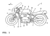
- FIG. 1 is a side view of a motorcycle according to an embodiment.
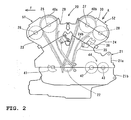
- FIG. 2 is a side view of a motorcycle engine according to the embodiment shown in FIG. 1.
- FIGs. 3 through 10 are explanatory views for a detailed structure of a camshaft drive mechanism according to the embodiment.
- a motorcycle 1 of this embodiment is described as follows with reference to FIGs. 1 through 10.
- the arrow F in the drawings indicates the forward direction in which the motorcycle 1 moves.
- the motorcycle 1 of this embodiment has a head pipe 2 and a main frame 3 connecting its front end to the head pipe 2.
- the main frame 3 is formed to extend rearward.
- a front wheel 5 is rotatably attached to the head pipe 2 via a front fork 4.
- Handlebars 6 are fixed to a top end of the head pipe 2.
- a rear wheel 8 is rotatably attached to the rear of a rear arm 7.
- a fuel tank 9 is installed above the main frame 3. At the rear of the fuel tank 9, a driver's seat 10 is provided.
- a down pipe 11 extending downward.
- a water-cooled V-type, 4-cylinder engine 20 is mounted between the down pipe 11 and the lower end of the main frame 3.
- a radiator 12 for cooling a coolant to circulate within the V-type, 4-cylinder engine 20 is installed in front of the down pipe 11.
- the V-type, 4-cylinder engine 20 is provided with a crankcase 21 for accommodating a crankshaft 22, which is made up of an upper crankcase 21a and a lower crankcase 21b.
- a crankcase 21 for accommodating a crankshaft 22, which is made up of an upper crankcase 21a and a lower crankcase 21b.
- main cylinder bodies (not shown) are integrally formed with each other on the upper crankcase 21a of the crankcase 21.
- a cylinder head 23 tilting forward to form a front bank 51 and a cylinder head 24 tilting rearward to form a rear bank 52 are mounted to the topside of the main cylinder body.
- the front bank 51 is an example as a "first bank” in the meaning of the present specification while the rear bank 52 is an example as the "second bank” in the meaning of the present specification.
- the cylinder head 23 is an example as the "first cylinder head” in the meaning of the present specification while the cylinder head 24 is an example as the “second cylinder head” in the meaning of the present specification.
- Top covers 40a and 40b are attached to the topside of the cylinder heads 23 and 24, respectively.
- the crankshaft 22 has two sprockets 22a and 22b as shown in FIG. 3.
- FIG. 2 shows that a balance weight 41, a crankshaft 22, a primary shaft 42 and a secondary shaft 43 are placed, in order from front to back, on a mating face between the upper crankcase 21a and the lower crankcase 21b.
- the balance weight 41 rotates at the same speed as the crankshaft 22 but in a direction reverse to that, and has a main function to absorb the primary vibration of the crankshaft 22.
- the primary shaft 42 and the secondary shaft 43 are respectively provided with a group of a number of speed change gears (not shown).
- the primary shaft 42, the secondary shaft 43 and the groups of speed change gears constitute a transmission 44.
- a housing portion for housing the transmission 44 is integrally formed with the crankcase 21 rearward of the main cylinder body (not shown) on the side of the rear bank 52 on the crankcase 21.
- the rear bank 52 is positioned toward the housing portion for housing the transmission 44 while the front bank 51 is positioned on the opposite side to the housing portion for housing the transmission 44.
- an intake camshaft 25 having a sprocket 25a and a gear 25b, and an exhaust camshaft 26 having a gear 26a engaged with the gear 25b of the intake camshaft 25 are rotatably attached to the cylinder head 23 forming the front bank 51.
- a cam chain 29 is wound around between the sprocket 22a of the crankshaft 22 and the sprocket 25a of the intake camshaft 25 at the cylinder head 23 forming the front bank 51.
- the cam chain 29 on the side of the front bank 51 is located in chain chambers 23a and 21c which are located at the axial midsection of the intake camshaft 25 and the exhaust camshaft 26.
- a straight chain guide member 31 is provided on the side where the cam chain 29 for the front bank 51 is tightened, and in turn an arcuate chain guide member 32 is provided on the side where the cam chain 29 for the front bank 51 is loosened.
- the side where the cam chain 29 is tightened refers to the side where the cam chain 29 is tightened by rotating the crankshaft 22.
- the side where the cam chain 29 is loosened refers to the side where the cam chain 29 is loosened by rotating the crankshaft 22.
- the arcuate chain guide member 32 has a hole portion 32a as a rotational pivot, a pressed portion 32b, a vibration-absorbing portion 32c located toward the cylinder head 23 above the pressed portion 32b for absorbing the vibration of the cam chain 29, and a guide portion 32d for guiding the cam chain 29.
- the hole portion 32a of the chain guide member 32 for the front bank 51 is rotatably supported by a support shaft 37a of a support member 37 as shown in FIGs. 3 and 10.
- a cam chain tensioner 33 for pressing the loosened-side chain guide member 32 for the front bank 51 against the cam chain 29 is disposed between the front bank 51 and the rear bank 52.
- an intake camshaft 27 having a sprocket 27a and a gear 27b, and an exhaust camshaft 28 having a gear 28a engaged with the gear 27b of the intake camshaft 27 are rotatably attached to the cylinder head 24 forming the rear bank 52.
- the intake camshaft 27 is an example as the "first camshaft” in the meaning of the present specification while the gear 27b is an example as the “first gear” in the meaning of the present specification.
- the exhaust camshaft 28 is an example as the "second camshaft” in the meaning of the present specification while the gear 28a is an example as the "second gear” in the meaning of the present specification.
- a cam chain 30 is wound around between the sprocket 22b of the crankshaft 22 and the sprocket 27a of the intake camshaft 27 on the cylinder head 24 forming the rear bank 52.
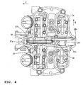
- the cam chain 30 on the side of the rear bank 52 is located in the chain chambers 24a and 21d (see FIG. 3) which are located at the axial (B direction in FIG. 4) midsection of the intake camshaft 27 and the exhaust camshaft 28.
- the embodiment employs a center cam chain system.
- a straight chain guide member 34 is provided on the side where the cam chain 30 for the rear bank 52 is tightened, and in turn an arcuate chain guide member 35 is provided on the side where the cam chain 30 is loosened.
- the arcuate chain guide member 35 has a hole portion 35a as a rotational pivot, a pressed portion 35b, a vibration-absorbing portion 35c located toward the cylinder head 24 above the pressed portion 35b for absorbing the vibration of the cam chain 30, and a guide portion 35d for guiding the cam chain 30.
- the hole portion 35a of the chain guide member 35 on the side of the rear bank 52 is supported by a support shaft 37b of a support member 37 as shown in FIGs. 3 and 10.
- a cam chain tensioner 36 for pressing the loosened-side chain guide member 35 for the rear bank 52 is disposed.
- the cam chain tensioner 36 is an example as the "tension applying member" in the meaning of the present specification.
- the cam chain tensioner 36 on the side of the rear bank 52 is provided below the exhaust camshaft 28 as shown in FIGs. 2 and 3.
- the cam chain 30 is wound not around the exhaust camshaft 28 but around the intake camshaft 27, which results in no cam chain 30 being located below the exhaust camshaft 28.
- This allows the cam chain tensioner 36 to be located below the exhaust camshaft 28 on the side of the rear bank 52, thereby preventing the cam chain tensioner 36 from protruding outward of the exhaust camshaft 28.
- Engagement of the gear 27b of the intake camshaft 27 with the gear 28a of the exhaust camshaft 28 enables the rotation of the intake camshaft 27 to be transmitted to the exhaust camshaft 28.
- the cam chain tensioner 36 on the side of the rear bank 52 is located across the mating face 24b of the cylinder head 24 and the upper crankcase 21 a, as shown in FIGs. 2 and 3. More specifically, as shown in FIG. 3, the cam chain tensioner 36 on the side of the rear bank 52 has a mounting portion 36a located inside the cylinder head 24, and a pressing portion 36b located so as to protrude toward the upper crankcase 21 a for pressing the pressed portion 35b of the chain guide member 35.
- the mounting portion 36a of the cam chain tensioner 36 is provided with mounting holes 36c and 36d through which mounting screws 60 are inserted, and an oil supply port 36e, as shown in FIG. 7.
- the mounting holes 36c and 36d and the oil supply port 36e are designed to extend substantially in the vertical direction with respect to the mating face 24b (See FIG. 6) of the cylinder head 24 and the upper crankcase 21 a.
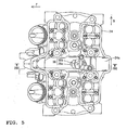
- the mounting holes 36c and 36d designed to extend substantially in the vertical direction (as shown by the arrow C in FIG. 6) with respect to the mating face 24b, allow the screws 60 to be inserted and secured from above the cylinder head 24 in the C direction of FIG. 6. This facilitates mounting of the mounting portion 36a of the cam chain tensioner 36 to the cylinder head 24.
- the oil supply port 36e is designed to connect to an oil passage 36f shown in FIG. 6 through another oil passage (not shown). The top end of the oil passage 36f is sealed by a ball-shaped plug 36g.
- FIG. 6 also shows that the pressing portion 36b of the cam tensioner 36 is provided with a protrusion 36i, which is inserted into an opening 36h and can move in a direction shown by the arrow D by given pitch.
- a compression coil spring 36j is provided for urging the protrusion 36i in the direction shown by the arrow D.
- a spring 36k for moving the protrusion 36i in the direction shown by the arrow D by given pitch is located such that the spring 36k abuts on the outer periphery of the protrusion 36i.
- a passage member 36l forming the oil passage is attached inside of the protrusion 36i.
- a check ball 36m which functions as a check valve for sealing the oil passage made of the passage member 36l, and a compression coil spring 36n for urging the check ball 36m in the direction in which the oil passage made of the passage member 36l is sealed.
- the protrusion 36i has a pin 36o attached to its side surface.
- a lock 36p which can rotate between the engaging position with respect to the pin 36o and the disengaging position, is provided.
- the lock 36p engages with the pin 36o under the initial condition (at the time when it has just been assembled).
- the protrusion 36i is thus prevented from moving in the D direction of FIG. 6. This dispenses with the need for a worker to press the tip end of the protrusion 36i not to protrude, when the worker assembles the pressing portion 36b of the cam chain tensioner 36 so as to press the pressed portion 35b of the chain guide member 35. This allows the worker to easily assemble the cam chain tensioner 36.
- the lock 36p When the cam chain tensioner 36 has been assembled, the lock 36p is rotated in the E direction of FIG. 6 due to the vibration created by driving the cam chain 30. This allows the lock 36p to be disengaged with the pin 36o. Disengagement of the lock 36p with the pin 36o causes the protrusion 36i to move by given pitch in the direction shown by the arrow D, depending on how much slack there is in the cam chain 30 with time. Therefore, the extent to which the protrusion 36i protrudes is automatically adjusted depending on how much slack there is in the cam chain 30, thereby preventing the cam chain 30 from being loosened for a long period of time.
- a passage member 36q that forms the oil passage to be connected to the oil passage 36f is fitted into the opening 36h.
- the check ball 36s which functions as a check valve for sealing the oil passage made of the passage member 36q, is placed inside of the opening 36h.
- a spring retainer 36r is disposed to retain the compression coil spring 36j and press the check ball 36s using an urging force produced by the compression coil spring 36j such that the oil passage made of the passage member 36q is sealed.
- the intake camshaft 25 and exhaust camshaft 26 on the side of the front bank 51 are driven with the rotation of the crankshaft 22.
- the counterclockwise rotation (see FIG. 3) of the crankshaft 22 is also transmitted to the intake camshaft 27 for the rear bank 52 through the cam chain 30 on the side of the rear bank 52.
- the rotation of the intake camshaft 27 is transmitted to the exhaust camshaft 28 for the rear bank 52 through the engagement of the gear 27b of the intake camshaft 27 with the gear 28a of the exhaust camshaft 28.
- the intake camshaft 27 and exhaust camshaft 28 on the side of the rear bank 52 are driven with the rotation of the crankshaft 22.
- the cam chain tensioner 36 on the side of the rear bank 52 for tensioning the cam chain 30 through the chain guide member 35 is mounted across the mating face between the cylinder head 24 and the upper crankcase 21 a.
- the pressing portion 36b of the cam chain tensioner 36 is located on the side of the upper crankcase 21 a, which allows the point where the cam chain tensioner 36 presses against the chain guide member 35 to be located downward of or apart from the upper end of the chain guide member 35. This can provide a longer length of the vibration-absorbing portion 35c formed between the point where the chain guide member 35 is pressed and the upper end thereof, so that the vibration-absorbing portion 35c tends to easily bend. This results in sufficient absorption of the vibration of the cam chain 30.
- the mounting portion 36a of the cam chain tensioner 36 is mounted inside of the cylinder head 24, as described above.
- a possible slight oil leakage from the cam chain tensioner 36 does not really matter because lubricant oil or other oils have already adhered to the inside of the cylinder head 24. Therefore, a sealing member such as O-ring is unnecessary, even if a hydraulic cam chain tensioner 36 is employed.
- the above embodiment shows an application to the center cam chain system in which the cam chain is located in the chain chamber which is located at the axial midsection of the intake and exhaust camshaft.
- the teaching of the embodiment is not limited to that, but it may also be applied to a side cam chain system in which the cam chain is located in the chain chamber which is located at the axial end of the intake and exhaust camshaft.
- the chain chamber should be formed inside of the cylinder head as a premise for the application of the teaching of the present embodiment.
- the tension applying means of the present embodiment is applied to the cam chain tensioner on the side of the rear bank.
- the teaching of the present embodiment is not limited to that, and may also be applied to the cam chain tensioner on the side of the front bank.
- teaching of the present embodiment is not limited to that, and may also be applied to V-type, 4-cylinder engines to be mounted to vehicles other than motorcycles, such as three-wheelers and ATVs (All Terrain Vehicles). Still furthermore, the teaching of the present embodiment may also be applied to V-type cylinder engines other than V-type, 4-cylinder engines, or other types of engines.
- an engine comprising: a crankcase, on which a main cylinder body is integrally formed, for accommodating a crankshaft; a cylinder head mounted above the crankcase; a chain chamber formed inside of the cylinder head; a camshaft provided at the cylinder head; a cam chain located in the chain chamber for transmitting a driving force of the crankshaft to the camshaft; a chain guide member for guiding the cam chain; and a tension applying member for tensioning the cam chain via the chain guide member.
- the tension applying member is mounted across a mating face between the cylinder head and the crankcase.
- the tension applying member for tensioning the cam chain via the chain guide member is mounted across the mating face between the cylinder head and the crankcase, as described above.
- a pressing portion of the tension applying member against the chain guide member is located toward the crankcase, which allows a point where the tension applying member presses against the chain guide member to be located downward of or apart from the upper end of the chain guide member.
- This can provide a longer length of a vibration-absorbing portion formed between the point where the chain guide member is pressed and the upper end thereof, so that the vibration-absorbing portion of the chain guide member tends to easily bend. This results in sufficient absorption of the vibration of the cam chain.
- an engine in which the tension applying member preferably includes a mounting portion to be mounted to the cylinder head, and a pressing portion, which protrudes toward the crankcase, for pressing the chain guide member.
- the tension applying member preferably includes a mounting portion to be mounted to the cylinder head, and a pressing portion, which protrudes toward the crankcase, for pressing the chain guide member.
- the mounting portion of the tension applying member is preferably mounted inside of the cylinder head. According to such an arrangement, even if a hydraulic tension applying member is used, for example, a possible slight oil leakage from the hydraulic tension applying member does not really matter because lubricant oil or other oils have already adhered to the inside of the cylinder head. Therefore, a sealing member such as O-ring is unnecessary for the use of the hydraulic tension applying member.
- the crankcase may include a housing portion for housing a transmission
- the cylinder head may include a first cylinder head mounted above the crankcase to be positioned opposite to the housing portion for housing the transmission in the crankcase and adapted to form a first bank
- a second cylinder head mounted above the crankcase to be positioned toward the housing portion for housing the transmission in the crankcase and adapted to form a second bank
- the tension applying member may be mounted across the mating face between the crankcase and the second cylinder head forming the second bank.
- an engine in which the chain chamber may be located at the axial midsection of the camshaft provided at the cylinder head.
- Such an arrangement allows the vibration of the cam chain to be sufficiently absorbed in any center cam chain type engine.
- an engine in which preferably the chain guide member is mounted toward the crankcase and includes: a pressed portion to be pressed by the tension applying member; and a vibration-absorbing portion that extends from the pressed portion toward the cylinder head and is deformable or bendable depending on the vibration of the cam chain.
- the chain guide member is mounted toward the crankcase and includes: a pressed portion to be pressed by the tension applying member; and a vibration-absorbing portion that extends from the pressed portion toward the cylinder head and is deformable or bendable depending on the vibration of the cam chain.
- an engine in which preferably the camshaft is connected to the crankshaft through the cam chain and includes: a first camshaft having a first gear; and a second camshaft having a second gear engaged with the first gear of the first camshaft, and the tension applying member is provided so as to press, via the chain guide member, against the loosened-side of the cam chain wound around between the first camshaft and the crankshaft.
- the cam chain is wound not around the second camshaft but around the first camshaft, which results in no cam chain being located below the second camshaft.
- the mounting portion of the tension applying member may include a mounting hole extending substantially in the vertical direction with respect to the mating face between the cylinder head and the crankcase.
- a mounting hole extending substantially in the vertical direction with respect to the mating face between the cylinder head and the crankcase.
- the tension applying member may be a hydraulic tension applying member and the mounting portion of the tension applying member may further include an oil supply port extending substantially parallel to the mounting hole.
- an engine comprising: a crankcase 21, on which a main cylinder body is integrally formed, for accommodating a crankshaft 22; a cylinder head 24 mounted above the crankcase 21; a chain chamber 24a formed inside of the cylinder head 24; an intake camshaft 27 and exhaust camshaft 28 provided at the cylinder head 24; a cam chain 30 located in the chain chamber 24a for transmitting a driving force of the crankshaft 22 to the intake camshaft 27; a chain guide member 35 for guiding the cam chain 30; and a cam chain tensioner 36 for tensioning the cam chain 30 via the chain guide member 35.
- the cam chain tensioner 36 is mounted across a mating face between the cylinder head 24 and the crankcase 21.
Landscapes
- Engineering & Computer Science (AREA)
- Mechanical Engineering (AREA)
- General Engineering & Computer Science (AREA)
- Devices For Conveying Motion By Means Of Endless Flexible Members (AREA)
- Valve-Gear Or Valve Arrangements (AREA)
- Valve Device For Special Equipments (AREA)
Abstract
Description
- The present invention relates to an engine according to the preamble portion of claim 1, and particularly to an engine provided with a crankcase on which a main cylinder body is integrally formed.
- A conventional motorcycle engine has a piston disposed for reciprocating motion inside of a cylinder, and a crankshaft connected to the piston via a connecting rod. This allows the reciprocating motion of the piston to be converted into a rotational motion of the crankshaft. As this type of conventional motorcycle engine, a V-type, 4-cylinder engine, provided with a crankcase on which a main cylinder body is integrally formed, is well known (See JP-A-Hei 4-075364). JP-A-Hei 4-075364 discloses a V-type, 4-cylinder engine including: a crankcase divided into an upper and a lower crankcase and having a main cylinder body integrally formed on the upper crankcase; a cylinder head mounted to the top side of the main cylinder body on the crankcase and tilting forward to form a front bank; another cylinder head also mounted to the topside of the main cylinder body on the crankcase and tilting rearward to form a rear bank; an intake and an exhaust camshaft each mounted to the corresponding cylinder head forming the front or rear bank; a cam chain for transmitting a rotary motion of the crankshaft to the intake and exhaust camshaft; a chain guide member for guiding the loosened-side cam chain; and a cam chain tensioner for tensioning the cam chain through the chain guide member.
- The V-type, 4-cylinder engine disclosed in JP-A-Hei 4-075364 has a chain chamber for accommodating the cam chain provided inside the cylinder head and the crankcase. A housing portion for housing a transmission is integrally formed at the rear of the main cylinder body for the rear bank on the crankcase.
- However, in the conventional V-type, 4-cylinder engine disclosed in JP-A-Hei 4-075364, the main cylinder body is integrally formed with the crankcase. This makes it difficult to mount the cam chain tensioner (tension applying member) toward the main cylinder body. Particularly, a housing portion for housing a transmission is provided rearward of the main cylinder body on the crankcase on the side of the rear bank, which makes it more difficult to mount the cam chain tensioner (tension applying member) toward the main cylinder body. Therefore, there arises a need for the cam chain tensioner (tension applying member) to be mounted toward the cylinder head.
- In such a case, the lower part of the chain guide member is located toward the main cylinder body while the upper part thereof is located toward the cylinder head in JP-A-Hei 4-075364. So, if the cam chain tensioner (tension applying member) is mounted toward the cylinder head, a point, where the cam chain tensioner presses against the chain guide member, disadvantageously results in being closer to the upper end of the chain guide member inside of the cylinder head. As described above, a portion that is closer to the upper end of the chain guide member is pressed by the cam chain tensioner, which results in a shorter length of a vibration-absorbing portion formed between the point where the chain guide member is pressed and the upper end thereof. This makes the vibration-absorbing portion of the chain guide member less bendable. This creates a problem of difficulty in sufficiently absorbing the vibration of the cam chain in JP-A-Hei 4-075364.
- The present invention is designed to solve the aforementioned problems, and therefore an object of the invention is to provide an engine as indicated above capable of sufficiently absorbing the vibration of the cam chain.
- This objective is solved in an inventive manner by an engine comprising a crankcase, on which a main cylinder body is integrally formed, and accommodating a crankshaft, a cylinder head mounted above the crankcase, a camshaft provided at the cylinder head, a cam chain for transmitting a driving force of the crankshaft to the camshaft, a chain guide member for guiding the cam chain, and a tension applying member for tensioning the cam chain via the chain guide member, wherein the tension applying member is mounted across a mating face between the cylinder head and the crankcase.
- Beneficially, the engine is provided with a chain chamber formed inside of the cylinder head, wherein the cam chain is located in the chain chamber for transmitting the driving force of the crankshaft to the camshaft. Therein, the chain chamber may be located at an axial midsection of the camshaft provided at the cylinder head.
- Further, the tension applying member might be provided below the camshaft.
- Moreover, a preferred embodiment includes a first camshaft having a first gear, and a second camshaft having a second gear engaged with the first gear of the first camshaft, wherein the first camshaft is connected to the crankshaft through the cam chain. Therein, the first camshaft may be an intake camshaft and the second camshaft may be an exhaust camshaft, wherein the cam chain may be wound around the intake camshaft, and by an engagement of a gear of the intake camshaft with a gear of the exhaust camshaft rotation of the intake camshaft may be transmitted to the exhaust camshaft.
- According to another preferred embodiment, the tension applying member is provided so as to press, via the chain guide member, against the loosened-side of the cam chain wound around between the camshaft and the crankshaft.
- According to yet another preferred embodiment, the chain guide member is mounted toward the crankcase and includes a pressed portion to be pressed by the tension applying member, and a vibration-absorbing portion that extends from the pressed portion toward the cylinder head and is deformable and/or bendable depending on the vibration of the cam chain.
- Further, the chain guide member may include a hole portion as a rotational pivot.
- According to still another embodiment, the tension applying member includes a mounting portion to be mounted to the cylinder head, and a pressing portion, which protrudes toward the crankcase, for pressing the chain guide member. Therein, the mounting portion of the tension applying member may be mounted inside of the cylinder head. Also, the mounting portion of the tension applying member may include a mounting hole extending substantially in a vertical direction with respect to the mating face between the cylinder head and the crankcase.
- Preferably, the tension applying member is a hydraulic tension applying member.
- Therein, the mounting portion of the tension applying member may include an oil supply port extending substantially parallel to the mounting hole.
- According to a further preferred embodiment, the crankcase includes a housing portion for housing a transmission, wherein the engine includes a first cylinder head mounted above the crankcase to be positioned opposite to the housing portion for housing the transmission and adapted to form a first bank, and a second cylinder head mounted above the crankcase to be positioned toward the housing portion for housing the transmission and adapted to form a second bank, wherein the tension applying member is mounted across a mating face between the crankcase and the second cylinder head forming the second bank.
- In the following, the present invention is explained in greater detail with respect to several embodiments thereof in conjunction with the accompanying drawings, wherein:
- FIG. 1
- is a side view of a motorcycle according to an embodiment;
- FIG. 2
- is a side view of a V-type, 4-cylinder engine for a motorcycle according to the embodiment;
- FIG. 3
- is a sectional view, showing a camshaft drive mechanism of the V-type, 4-cylinder engine according to the embodiment of FIG. 2;
- FIG. 4
- is a top plan view of a cylinder head on the side of the rear bank, when the V4-cylinder according to the embodiment of FIG. 2 is viewed from the direction shown by the arrow A;
- FIG. 5
- is a top plan view of the cylinder head on the side of the rear bank with the camshaft drive mechanism shown in FIG. 4 removed from the cylinder head;
- FIG. 6
- is a cross-sectional view, taken along the line 200-200 in FIG. 5;
- FIG. 7
- is a perspective view of a cam chain tensioner shown in FIG. 6;
- FIG. 8
- is a front view, showing a tightened-side chain guide for the rear bank of FIG. 3;
- FIG. 9
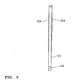
- is a left side view of the tightened-side chain guide for the rear bank of FIG. 8; and
- FIG. 10
- is a cross-sectional view of a support member, for supporting the tightened-side chain guide member, taken along the line 100-100 in FIG. 3.
- An embodiment is described below with reference to the drawings.
- FIG. 1 is a side view of a motorcycle according to an embodiment. FIG. 2 is a side view of a motorcycle engine according to the embodiment shown in FIG. 1. FIGs. 3 through 10 are explanatory views for a detailed structure of a camshaft drive mechanism according to the embodiment. A motorcycle 1 of this embodiment is described as follows with reference to FIGs. 1 through 10. The arrow F in the drawings indicates the forward direction in which the motorcycle 1 moves.
- The motorcycle 1 of this embodiment has a
head pipe 2 and amain frame 3 connecting its front end to thehead pipe 2. Themain frame 3 is formed to extend rearward. Afront wheel 5 is rotatably attached to thehead pipe 2 via afront fork 4.Handlebars 6 are fixed to a top end of thehead pipe 2. Arear wheel 8 is rotatably attached to the rear of arear arm 7. Afuel tank 9 is installed above themain frame 3. At the rear of thefuel tank 9, a driver'sseat 10 is provided. - To the
head pipe 2 is attached adown pipe 11 extending downward. A water-cooled V-type, 4-cylinder engine 20 is mounted between thedown pipe 11 and the lower end of themain frame 3. Aradiator 12 for cooling a coolant to circulate within the V-type, 4-cylinder engine 20 is installed in front of thedown pipe 11. - As shown in FIG. 2, the V-type, 4-
cylinder engine 20 according to this embodiment is provided with acrankcase 21 for accommodating acrankshaft 22, which is made up of anupper crankcase 21a and alower crankcase 21b. Four main cylinder bodies (not shown) are integrally formed with each other on theupper crankcase 21a of thecrankcase 21. Acylinder head 23 tilting forward to form afront bank 51 and acylinder head 24 tilting rearward to form arear bank 52 are mounted to the topside of the main cylinder body. Thefront bank 51 is an example as a "first bank" in the meaning of the present specification while therear bank 52 is an example as the "second bank" in the meaning of the present specification. Thecylinder head 23 is an example as the "first cylinder head" in the meaning of the present specification while thecylinder head 24 is an example as the "second cylinder head" in the meaning of the present specification. Top covers 40a and 40b are attached to the topside of the cylinder heads 23 and 24, respectively. Thecrankshaft 22 has twosprockets - FIG. 2 shows that a
balance weight 41, acrankshaft 22, aprimary shaft 42 and asecondary shaft 43 are placed, in order from front to back, on a mating face between theupper crankcase 21a and thelower crankcase 21b. Thebalance weight 41 rotates at the same speed as thecrankshaft 22 but in a direction reverse to that, and has a main function to absorb the primary vibration of thecrankshaft 22. Theprimary shaft 42 and thesecondary shaft 43 are respectively provided with a group of a number of speed change gears (not shown). Theprimary shaft 42, thesecondary shaft 43 and the groups of speed change gears constitute atransmission 44. A housing portion for housing thetransmission 44 is integrally formed with thecrankcase 21 rearward of the main cylinder body (not shown) on the side of therear bank 52 on thecrankcase 21. In other words, therear bank 52 is positioned toward the housing portion for housing thetransmission 44 while thefront bank 51 is positioned on the opposite side to the housing portion for housing thetransmission 44. - As shown in FIG. 3, an
intake camshaft 25 having asprocket 25a and agear 25b, and anexhaust camshaft 26 having agear 26a engaged with thegear 25b of theintake camshaft 25 are rotatably attached to thecylinder head 23 forming thefront bank 51. Acam chain 29 is wound around between thesprocket 22a of thecrankshaft 22 and thesprocket 25a of theintake camshaft 25 at thecylinder head 23 forming thefront bank 51. Thecam chain 29 on the side of thefront bank 51 is located inchain chambers intake camshaft 25 and theexhaust camshaft 26. - As shown in FIG. 3, a straight
chain guide member 31 is provided on the side where thecam chain 29 for thefront bank 51 is tightened, and in turn an arcuatechain guide member 32 is provided on the side where thecam chain 29 for thefront bank 51 is loosened. The side where thecam chain 29 is tightened refers to the side where thecam chain 29 is tightened by rotating thecrankshaft 22. The side where thecam chain 29 is loosened refers to the side where thecam chain 29 is loosened by rotating thecrankshaft 22. The arcuatechain guide member 32 has ahole portion 32a as a rotational pivot, a pressedportion 32b, a vibration-absorbingportion 32c located toward thecylinder head 23 above the pressedportion 32b for absorbing the vibration of thecam chain 29, and aguide portion 32d for guiding thecam chain 29. Thehole portion 32a of thechain guide member 32 for thefront bank 51 is rotatably supported by asupport shaft 37a of asupport member 37 as shown in FIGs. 3 and 10. Acam chain tensioner 33 for pressing the loosened-sidechain guide member 32 for thefront bank 51 against thecam chain 29 is disposed between thefront bank 51 and therear bank 52. - In this embodiment, as shown in FIG. 3, an
intake camshaft 27 having asprocket 27a and agear 27b, and anexhaust camshaft 28 having agear 28a engaged with thegear 27b of theintake camshaft 27 are rotatably attached to thecylinder head 24 forming therear bank 52. Theintake camshaft 27 is an example as the "first camshaft" in the meaning of the present specification while thegear 27b is an example as the "first gear" in the meaning of the present specification. Theexhaust camshaft 28 is an example as the "second camshaft" in the meaning of the present specification while thegear 28a is an example as the "second gear" in the meaning of the present specification. Acam chain 30 is wound around between thesprocket 22b of thecrankshaft 22 and thesprocket 27a of theintake camshaft 27 on thecylinder head 24 forming therear bank 52. Thecam chain 30 on the side of therear bank 52 is located in thechain chambers intake camshaft 27 and theexhaust camshaft 28. In short, the embodiment employs a center cam chain system. - In this embodiment, a straight
chain guide member 34 is provided on the side where thecam chain 30 for therear bank 52 is tightened, and in turn an arcuatechain guide member 35 is provided on the side where thecam chain 30 is loosened. As shown in FIGs. 8 and 9, the arcuatechain guide member 35 has ahole portion 35a as a rotational pivot, a pressedportion 35b, a vibration-absorbingportion 35c located toward thecylinder head 24 above the pressedportion 35b for absorbing the vibration of thecam chain 30, and aguide portion 35d for guiding thecam chain 30. Thehole portion 35a of thechain guide member 35 on the side of therear bank 52 is supported by asupport shaft 37b of asupport member 37 as shown in FIGs. 3 and 10. Acam chain tensioner 36 for pressing the loosened-sidechain guide member 35 for therear bank 52 is disposed. Thecam chain tensioner 36 is an example as the "tension applying member" in the meaning of the present specification. - The
cam chain tensioner 36 on the side of therear bank 52 is provided below theexhaust camshaft 28 as shown in FIGs. 2 and 3. To be more specific, in this embodiment, thecam chain 30 is wound not around theexhaust camshaft 28 but around theintake camshaft 27, which results in nocam chain 30 being located below theexhaust camshaft 28. This allows thecam chain tensioner 36 to be located below theexhaust camshaft 28 on the side of therear bank 52, thereby preventing thecam chain tensioner 36 from protruding outward of theexhaust camshaft 28. Engagement of thegear 27b of theintake camshaft 27 with thegear 28a of theexhaust camshaft 28 enables the rotation of theintake camshaft 27 to be transmitted to theexhaust camshaft 28. This can reduce a distance between theintake camshaft 27 and theexhaust camshaft 28, compared to the case where thecam chain 30 is wound around between theintake camshaft 27 and theexhaust camshaft 28 to transmit the rotation from theintake camshaft 27 to theexhaust camshaft 28. This makes it possible to make a shape of a combustion chamber (not shown) undersurface of thecylinder head 24 flatter, resulting in improved combustion efficiency. - In the embodiment, the
cam chain tensioner 36 on the side of therear bank 52 is located across themating face 24b of thecylinder head 24 and theupper crankcase 21 a, as shown in FIGs. 2 and 3. More specifically, as shown in FIG. 3, thecam chain tensioner 36 on the side of therear bank 52 has a mountingportion 36a located inside thecylinder head 24, and apressing portion 36b located so as to protrude toward theupper crankcase 21 a for pressing the pressedportion 35b of thechain guide member 35. The mountingportion 36a of thecam chain tensioner 36 is provided with mountingholes oil supply port 36e, as shown in FIG. 7. The mountingholes oil supply port 36e are designed to extend substantially in the vertical direction with respect to themating face 24b (See FIG. 6) of thecylinder head 24 and theupper crankcase 21 a. The mountingholes mating face 24b, allow thescrews 60 to be inserted and secured from above thecylinder head 24 in the C direction of FIG. 6. This facilitates mounting of the mountingportion 36a of thecam chain tensioner 36 to thecylinder head 24. Theoil supply port 36e is designed to connect to an oil passage 36f shown in FIG. 6 through another oil passage (not shown). The top end of the oil passage 36f is sealed by a ball-shapedplug 36g. - FIG. 6 also shows that the
pressing portion 36b of thecam tensioner 36 is provided with a protrusion 36i, which is inserted into anopening 36h and can move in a direction shown by the arrow D by given pitch. A compression coil spring 36j is provided for urging the protrusion 36i in the direction shown by the arrow D. In addition, aspring 36k for moving the protrusion 36i in the direction shown by the arrow D by given pitch is located such that thespring 36k abuts on the outer periphery of the protrusion 36i. Inside of the protrusion 36i, a passage member 36l forming the oil passage is attached. Also, inside of the protrusion 36i, acheck ball 36m which functions as a check valve for sealing the oil passage made of the passage member 36l, and acompression coil spring 36n for urging thecheck ball 36m in the direction in which the oil passage made of the passage member 36l is sealed. - The protrusion 36i has a pin 36o attached to its side surface. A
lock 36p, which can rotate between the engaging position with respect to the pin 36o and the disengaging position, is provided. Thelock 36p engages with the pin 36o under the initial condition (at the time when it has just been assembled). The protrusion 36i is thus prevented from moving in the D direction of FIG. 6. This dispenses with the need for a worker to press the tip end of the protrusion 36i not to protrude, when the worker assembles thepressing portion 36b of thecam chain tensioner 36 so as to press the pressedportion 35b of thechain guide member 35. This allows the worker to easily assemble thecam chain tensioner 36. When thecam chain tensioner 36 has been assembled, thelock 36p is rotated in the E direction of FIG. 6 due to the vibration created by driving thecam chain 30. This allows thelock 36p to be disengaged with the pin 36o. Disengagement of thelock 36p with the pin 36o causes the protrusion 36i to move by given pitch in the direction shown by the arrow D, depending on how much slack there is in thecam chain 30 with time. Therefore, the extent to which the protrusion 36i protrudes is automatically adjusted depending on how much slack there is in thecam chain 30, thereby preventing thecam chain 30 from being loosened for a long period of time. - A
passage member 36q that forms the oil passage to be connected to the oil passage 36f is fitted into theopening 36h. Thecheck ball 36s, which functions as a check valve for sealing the oil passage made of thepassage member 36q, is placed inside of theopening 36h. Also, inside of theopening 36h, aspring retainer 36r is disposed to retain the compression coil spring 36j and press thecheck ball 36s using an urging force produced by the compression coil spring 36j such that the oil passage made of thepassage member 36q is sealed. - Now, operations of the
intake camshaft 25 andexhaust camshaft 26 for thefront bank 51 as well as those of theintake camshaft 27 andexhaust camshaft 28 for therear bank 52 are described with reference to FIG. 3. First, reciprocating motion of the piston (not shown) results in a counterclockwise rotation of thecrankshaft 22, which is transmitted to theintake camshaft 25 for thefront bank 51 via thecam chain 29 on the side of thefront bank 51. The rotation of theintake camshaft 25 for thefront bank 51 is transmitted to theexhaust camshaft 26 for thefront bank 51 through the engagement of thegear 25b of theintake camshaft 25 with thegear 26a of theexhaust camshaft 26. Thus, theintake camshaft 25 andexhaust camshaft 26 on the side of thefront bank 51 are driven with the rotation of thecrankshaft 22. The counterclockwise rotation (see FIG. 3) of thecrankshaft 22 is also transmitted to theintake camshaft 27 for therear bank 52 through thecam chain 30 on the side of therear bank 52. The rotation of theintake camshaft 27 is transmitted to theexhaust camshaft 28 for therear bank 52 through the engagement of thegear 27b of theintake camshaft 27 with thegear 28a of theexhaust camshaft 28. Thus, theintake camshaft 27 andexhaust camshaft 28 on the side of therear bank 52 are driven with the rotation of thecrankshaft 22. - As described above, in this embodiment, the
cam chain tensioner 36 on the side of therear bank 52 for tensioning thecam chain 30 through thechain guide member 35 is mounted across the mating face between thecylinder head 24 and theupper crankcase 21 a. Also, thepressing portion 36b of thecam chain tensioner 36 is located on the side of theupper crankcase 21 a, which allows the point where thecam chain tensioner 36 presses against thechain guide member 35 to be located downward of or apart from the upper end of thechain guide member 35. This can provide a longer length of the vibration-absorbingportion 35c formed between the point where thechain guide member 35 is pressed and the upper end thereof, so that the vibration-absorbingportion 35c tends to easily bend. This results in sufficient absorption of the vibration of thecam chain 30. - Further, in this embodiment, the mounting
portion 36a of thecam chain tensioner 36 is mounted inside of thecylinder head 24, as described above. Thus, a possible slight oil leakage from thecam chain tensioner 36 does not really matter because lubricant oil or other oils have already adhered to the inside of thecylinder head 24. Therefore, a sealing member such as O-ring is unnecessary, even if a hydrauliccam chain tensioner 36 is employed. - It should be conceivable that the embodiment is disclosed herein simply for the purpose of showing an example in all respects, rather than the limitation.
- The above embodiment shows an application to the center cam chain system in which the cam chain is located in the chain chamber which is located at the axial midsection of the intake and exhaust camshaft. However, the teaching of the embodiment is not limited to that, but it may also be applied to a side cam chain system in which the cam chain is located in the chain chamber which is located at the axial end of the intake and exhaust camshaft. Nevertheless, the chain chamber should be formed inside of the cylinder head as a premise for the application of the teaching of the present embodiment.
- In the above description of the embodiment, an example is shown in which the tension applying means of the present embodiment is applied to the cam chain tensioner on the side of the rear bank. However, the teaching of the present embodiment is not limited to that, and may also be applied to the cam chain tensioner on the side of the front bank.
- Furthermore, in the above description of the embodiment, an example is shown in which the teaching thereof is applied to the V-type, 4-cylinder engine for motorcycles. However, the teaching of the present embodiment is not limited to that, and may also be applied to V-type, 4-cylinder engines to be mounted to vehicles other than motorcycles, such as three-wheelers and ATVs (All Terrain Vehicles). Still furthermore, the teaching of the present embodiment may also be applied to V-type cylinder engines other than V-type, 4-cylinder engines, or other types of engines.
- The description above discloses (amongst others) an embodiment with an engine comprising: a crankcase, on which a main cylinder body is integrally formed, for accommodating a crankshaft; a cylinder head mounted above the crankcase; a chain chamber formed inside of the cylinder head; a camshaft provided at the cylinder head; a cam chain located in the chain chamber for transmitting a driving force of the crankshaft to the camshaft; a chain guide member for guiding the cam chain; and a tension applying member for tensioning the cam chain via the chain guide member. The tension applying member is mounted across a mating face between the cylinder head and the crankcase.
- As for the engine according to this embodiment, the tension applying member for tensioning the cam chain via the chain guide member is mounted across the mating face between the cylinder head and the crankcase, as described above. Thus, a pressing portion of the tension applying member against the chain guide member is located toward the crankcase, which allows a point where the tension applying member presses against the chain guide member to be located downward of or apart from the upper end of the chain guide member. This can provide a longer length of a vibration-absorbing portion formed between the point where the chain guide member is pressed and the upper end thereof, so that the vibration-absorbing portion of the chain guide member tends to easily bend. This results in sufficient absorption of the vibration of the cam chain.
- According to a further embodiment, there is provided an engine, in which the tension applying member preferably includes a mounting portion to be mounted to the cylinder head, and a pressing portion, which protrudes toward the crankcase, for pressing the chain guide member. Such a configuration makes it easier to locate the pressing portion toward the crankcase. Therefore, the point where the tension applying member presses against the chain guide member can be easily located downward of or apart from the upper end of the chain guide member.
- In such a case, the mounting portion of the tension applying member is preferably mounted inside of the cylinder head. According to such an arrangement, even if a hydraulic tension applying member is used, for example, a possible slight oil leakage from the hydraulic tension applying member does not really matter because lubricant oil or other oils have already adhered to the inside of the cylinder head. Therefore, a sealing member such as O-ring is unnecessary for the use of the hydraulic tension applying member.
- According to another embodiment, there is provided an engine, in which the crankcase may include a housing portion for housing a transmission, the cylinder head may include a first cylinder head mounted above the crankcase to be positioned opposite to the housing portion for housing the transmission in the crankcase and adapted to form a first bank, and a second cylinder head mounted above the crankcase to be positioned toward the housing portion for housing the transmission in the crankcase and adapted to form a second bank, and the tension applying member may be mounted across the mating face between the crankcase and the second cylinder head forming the second bank. According to such an arrangement, on the side of the second cylinder head forming the second bank, a point where the tension applying member presses against the chain guide member can be located downward of or apart from the upper end of the chain guide member. This can provide a longer length of the vibration-absorbing portion formed between the point where the chain guide member is pressed and the upper end thereof. Therefore, on the side of the second cylinder head forming the second bank, the vibration-absorbing portion of the chain guide member tends to easily bend, which results in sufficient absorption of the vibration of the cam chain on the side of the second bank.
- According to still another embodiment, there is provided an engine, in which the chain chamber may be located at the axial midsection of the camshaft provided at the cylinder head. Such an arrangement allows the vibration of the cam chain to be sufficiently absorbed in any center cam chain type engine.
- According to yet another embodiment, there is provided an engine, in which preferably the chain guide member is mounted toward the crankcase and includes: a pressed portion to be pressed by the tension applying member; and a vibration-absorbing portion that extends from the pressed portion toward the cylinder head and is deformable or bendable depending on the vibration of the cam chain. Such an arrangement allows the vibration of the cam chain to be absorbed easily by the vibration-absorbing portion extending toward the cylinder head.
- According to a further embodiment, there is provided an engine, in which preferably the camshaft is connected to the crankshaft through the cam chain and includes: a first camshaft having a first gear; and a second camshaft having a second gear engaged with the first gear of the first camshaft, and the tension applying member is provided so as to press, via the chain guide member, against the loosened-side of the cam chain wound around between the first camshaft and the crankshaft. According to such a configuration, the cam chain is wound not around the second camshaft but around the first camshaft, which results in no cam chain being located below the second camshaft. This allows the tension applying member to be located below the second camshaft, thereby preventing the tension applying member from protruding outward of the second camshaft. Engagement of the first gear with the second gear enables the rotation of the first camshaft to be transmitted to the second camshaft. This can reduce a distance between the first camshaft and the second camshaft, compared to the case where the cam chain is wound around between the first camshaft and the second camshaft to transmit the rotation from the first camshaft to the second camshaft. This makes it possible to make a shape of a combustion chamber undersurface of the cylinder head flatter, resulting in improved combustion efficiency.
- According to the embodiment of the engine, in which the tension applying member includes the mounting portion, the mounting portion of the tension applying member may include a mounting hole extending substantially in the vertical direction with respect to the mating face between the cylinder head and the crankcase. Such a configuration allows a screw to be inserted and secured into the mounting hole from above the cylinder head or in the substantially vertical direction with respect to the mating face between the cylinder head and the crankcase, when the mounting portion of the tension applying member is mounted to the cylinder head. This facilitates mounting of the mounting portion of the tension applying member to the cylinder head.
- In such a case, the tension applying member may be a hydraulic tension applying member and the mounting portion of the tension applying member may further include an oil supply port extending substantially parallel to the mounting hole.
- Hence, in order to provide an engine capable of sufficiently absorbing the vibration of a cam chain according to a most preferred embodiment, there is provided an engine comprising: a
crankcase 21, on which a main cylinder body is integrally formed, for accommodating acrankshaft 22; acylinder head 24 mounted above thecrankcase 21; achain chamber 24a formed inside of thecylinder head 24; anintake camshaft 27 andexhaust camshaft 28 provided at thecylinder head 24; acam chain 30 located in thechain chamber 24a for transmitting a driving force of thecrankshaft 22 to theintake camshaft 27; achain guide member 35 for guiding thecam chain 30; and acam chain tensioner 36 for tensioning thecam chain 30 via thechain guide member 35. Thecam chain tensioner 36 is mounted across a mating face between thecylinder head 24 and thecrankcase 21.
Claims (15)
- Engine comprising a crankcase (21), on which a main cylinder body is integrally formed, and accommodating a crankshaft (22), a cylinder head (24) mounted above the crankcase (21), a camshaft (28) provided at the cylinder head (24), a cam chain (30) for transmitting a driving force of the crankshaft (22) to the camshaft (28), a chain guide member (35) for guiding the cam chain (30), and a tension applying member (36) for tensioning the cam chain (30) via the chain guide member (35), characterized in that the tension applying member (36) is mounted across a mating face (24b) between the cylinder head (24) and the crankcase (21).
- Engine according to claim 1, characterized by a chain chamber (24a) formed inside of the cylinder head (24), wherein the cam chain (30) is located in the chain chamber (24a) for transmitting the driving force of the crankshaft (22) to the camshaft (28).
- Engine according to claim 2, characterized in that the chain chamber (24a) is located at an axial midsection of the camshaft (28) provided at the cylinder head (24).
- Engine according to one of the claims 1 to 3, characterized in that the tension applying member (36) is provided below the camshaft (28).
- Engine according to one of the claims 1 to 4, characterized by a first camshaft (27) having a first gear (27b), and a second camshaft (28) having a second gear (28a) engaged with the first gear (27b) of the first camshaft (27), wherein the first camshaft (27) is connected to the crankshaft (22) through the cam chain (30).
- Engine according to claim 5, characterized in that the first camshaft is an intake camshaft (27) and the second camshaft is an exhaust camshaft (28), wherein the cam chain (30) is wound around the intake camshaft (27), and by an engagement of a gear (27b) of the intake camshaft (27) with a gear (28a) of the exhaust camshaft (28) rotation of the intake camshaft (27) is transmitted to the exhaust camshaft (28).
- Engine according to one of the claims 1 to 6, characterized in that the tension applying member (36) is provided so as to press, via the chain guide member (35), against the loosened-side of the cam chain (30) wound around between the camshaft (27) and the crankshaft (22).
- Engine according to one of the claims 1 to 7, characterized in that the chain guide member (35) is mounted toward the crankcase (21) and includes a pressed portion (35b) to be pressed by the tension applying member (36), and a vibration-absorbing portion (35c) that extends from the pressed portion (35b) toward the cylinder head (24) and is deformable and/or bendable depending on the vibration of the cam chain (30).
- Engine according to one of the claims 1 to 8, characterized in that the chain guide member (35) includes a hole portion (35a) as a rotational pivot.
- Engine according to one of the claims 1 to 9, characterized in that the tension applying member (36) includes a mounting portion (36a) to be mounted to the cylinder head (24), and a pressing portion (36b), which protrudes toward the crankcase (21), for pressing the chain guide member (35).
- Engine according to claim 10, characterized in that the mounting portion (36a) of the tension applying member (36) is mounted inside of the cylinder head (24).
- Engine according to claim 10 or 11, characterized in that the mounting portion (36a) of the tension applying member (36) includes a mounting hole (36c,36d) extending substantially in a vertical direction with respect to the mating face (24b) between the cylinder head (24) and the crankcase (21).
- Engine according to one of the claims 1 to 12, characterized in that the tension applying member (35) is a hydraulic tension applying member.
- Engine according to claim 13, characterized in that the mounting portion of the tension applying member (35) includes an oil supply port (36e) extending substantially parallel to the mounting hole (36c,36d).
- Engine according to one of the claims 1 to 14, characterized in that the crankcase (21) includes a housing portion for housing a transmission (44), wherein the engine includes a first cylinder head (23) mounted above the crankcase (21) to be positioned opposite to the housing portion for housing the transmission (44) and adapted to form a first bank (51), and a second cylinder head (24) mounted above the crankcase (21) to be positioned toward the housing portion for housing the transmission (44) and adapted to form a second bank (52), wherein the tension applying member (35) is mounted across a mating face (24b) between the crankcase (21) and the second cylinder head (24) forming the second bank (52).
Applications Claiming Priority (2)
| Application Number | Priority Date | Filing Date | Title |
|---|---|---|---|
| JP2004181932 | 2004-06-21 | ||
| JP2004181932A JP2006002711A (en) | 2004-06-21 | 2004-06-21 | engine |
Publications (3)
| Publication Number | Publication Date |
|---|---|
| EP1609959A2 true EP1609959A2 (en) | 2005-12-28 |
| EP1609959A3 EP1609959A3 (en) | 2008-12-17 |
| EP1609959B1 EP1609959B1 (en) | 2010-08-18 |
Family
ID=35045258
Family Applications (1)
| Application Number | Title | Priority Date | Filing Date |
|---|---|---|---|
| EP05013370A Expired - Lifetime EP1609959B1 (en) | 2004-06-21 | 2005-06-21 | Engine |
Country Status (6)
| Country | Link |
|---|---|
| US (1) | US7455039B2 (en) |
| EP (1) | EP1609959B1 (en) |
| JP (1) | JP2006002711A (en) |
| CN (2) | CN100356047C (en) |
| AT (1) | ATE478238T1 (en) |
| DE (1) | DE602005022960D1 (en) |
Families Citing this family (5)
| Publication number | Priority date | Publication date | Assignee | Title |
|---|---|---|---|---|
| US8141673B2 (en) * | 2006-03-31 | 2012-03-27 | Honda Motor Co., Ltd. | Engine for saddle ride type vehicle |
| JP5078313B2 (en) * | 2006-10-17 | 2012-11-21 | 川崎重工業株式会社 | Motorcycle |
| US8701611B2 (en) * | 2011-12-06 | 2014-04-22 | Ford Global Technologies, Llc | Engine drive system |
| CN103511570B (en) * | 2012-06-26 | 2016-09-07 | 比亚迪股份有限公司 | a tensioning device |
| JP2015055242A (en) * | 2013-09-13 | 2015-03-23 | ヤマハモーターパワープロダクツ株式会社 | OHV engine |
Citations (2)
| Publication number | Priority date | Publication date | Assignee | Title |
|---|---|---|---|---|
| JPH0475364A (en) | 1990-07-17 | 1992-03-10 | Mitsubishi Electric Corp | Programmable logic array |
| JPH08135427A (en) | 1994-11-04 | 1996-05-28 | Suzuki Motor Corp | Timing chain lubrication structure |
Family Cites Families (13)
| Publication number | Priority date | Publication date | Assignee | Title |
|---|---|---|---|---|
| JPS5874810A (en) * | 1981-10-29 | 1983-05-06 | Honda Motor Co Ltd | Locking device in tensioner of timing chain of internal combustion engine |
| DE3326319A1 (en) * | 1983-07-21 | 1985-01-31 | Dr.Ing.H.C. F. Porsche Ag, 7000 Stuttgart | CHAIN DRIVE OF A PISTON PISTON INTERNAL COMBUSTION ENGINE |
| JPS6170262A (en) * | 1984-09-11 | 1986-04-11 | Suzuki Motor Co Ltd | Cam chain tensioner for four-cycle engine |
| JPS61145306A (en) * | 1984-12-20 | 1986-07-03 | Toyota Motor Corp | V6 DOHC internal combustion engine |
| JP4014185B2 (en) * | 1998-10-12 | 2007-11-28 | ヤマハ発動機株式会社 | Engine push rod cover structure |
| JP4122109B2 (en) * | 1999-05-31 | 2008-07-23 | 本田技研工業株式会社 | Parts mounting structure |
| DE19954481A1 (en) * | 1999-11-12 | 2001-05-23 | Porsche Ag | Chain guide for a control shaft drive of an internal combustion engine and method for producing a chain guide |
| JP3149876B1 (en) * | 2000-11-13 | 2001-03-26 | スズキ株式会社 | Chain tensioner device for internal combustion engine |
| JP4393718B2 (en) * | 2001-01-11 | 2010-01-06 | 本田技研工業株式会社 | V-type internal combustion engine |
| US6789517B2 (en) * | 2001-11-19 | 2004-09-14 | General Motors Corporation | Method for managing thermal load on an engine |
| JP3943403B2 (en) * | 2002-01-28 | 2007-07-11 | 富士重工業株式会社 | Engine camshaft pin mounting structure |
| JP4059318B2 (en) * | 2002-09-30 | 2008-03-12 | 本田技研工業株式会社 | Internal combustion engine cam chain fall-off prevention structure |
| US6976476B1 (en) * | 2004-09-21 | 2005-12-20 | International Engine Intellectual Property Company, Llc | Fuel pump drive system in an internal combustion engine |
-
2004
- 2004-06-21 JP JP2004181932A patent/JP2006002711A/en not_active Withdrawn
-
2005
- 2005-06-21 CN CNB2005100774357A patent/CN100356047C/en not_active Expired - Fee Related
- 2005-06-21 DE DE602005022960T patent/DE602005022960D1/en not_active Expired - Lifetime
- 2005-06-21 EP EP05013370A patent/EP1609959B1/en not_active Expired - Lifetime
- 2005-06-21 CN CN2007101535668A patent/CN101117899B/en not_active Expired - Fee Related
- 2005-06-21 US US11/157,637 patent/US7455039B2/en active Active
- 2005-06-21 AT AT05013370T patent/ATE478238T1/en not_active IP Right Cessation
Patent Citations (2)
| Publication number | Priority date | Publication date | Assignee | Title |
|---|---|---|---|---|
| JPH0475364A (en) | 1990-07-17 | 1992-03-10 | Mitsubishi Electric Corp | Programmable logic array |
| JPH08135427A (en) | 1994-11-04 | 1996-05-28 | Suzuki Motor Corp | Timing chain lubrication structure |
Also Published As
| Publication number | Publication date |
|---|---|
| CN101117899B (en) | 2010-06-16 |
| CN1712682A (en) | 2005-12-28 |
| CN101117899A (en) | 2008-02-06 |
| ATE478238T1 (en) | 2010-09-15 |
| US20050279308A1 (en) | 2005-12-22 |
| DE602005022960D1 (en) | 2010-09-30 |
| US7455039B2 (en) | 2008-11-25 |
| CN100356047C (en) | 2007-12-19 |
| EP1609959A3 (en) | 2008-12-17 |
| JP2006002711A (en) | 2006-01-05 |
| EP1609959B1 (en) | 2010-08-18 |
Similar Documents
| Publication | Publication Date | Title |
|---|---|---|
| US6481408B2 (en) | Engine unit of motorcycle | |
| US7690367B2 (en) | Internal combustion engine and vehicle having the internal combustion engine | |
| US20080178829A1 (en) | Cylinder head for an overhead-cam internal combustion engine, engine incorporating same, and vehicle incorporating the engine | |
| US20080223662A1 (en) | Internal combustion engine and vehicle having the internal combustion engine | |
| US8662253B2 (en) | Lubricating oil feeding structure | |
| US6557516B2 (en) | Engine unit for a vehicle | |
| US6364797B1 (en) | Motorcycle transmission | |
| CN100408821C (en) | internal combustion engine | |
| EP1609959B1 (en) | Engine | |
| US7913587B2 (en) | Internal combustion engine and vehicle having the internal combustion engine | |
| US9255628B2 (en) | Chain tensioner for internal combustion engine | |
| US10006523B2 (en) | Power unit having cam chain tensioner pivot mechanism | |
| US7267094B2 (en) | Lubrication system of small vehicle engine | |
| US7891328B2 (en) | Lubricating system for valve operating system | |
| JP5602697B2 (en) | Cam type torque damper | |
| JPH0585460A (en) | Sprocket positioning structure of power take off device for compact vehicle | |
| JP5329354B2 (en) | Internal combustion engine | |
| US20080087246A1 (en) | Engine and motorcycle | |
| US8910598B2 (en) | Vehicle internal combustion engine | |
| US8448620B2 (en) | Ignition device attachment structure for internal combustion engine | |
| JP7472756B2 (en) | engine | |
| JP4071512B2 (en) | V-type engine for vehicles | |
| US8590667B2 (en) | Crankcase of internal combustion engine |
Legal Events
| Date | Code | Title | Description |
|---|---|---|---|
| PUAI | Public reference made under article 153(3) epc to a published international application that has entered the european phase |
Free format text: ORIGINAL CODE: 0009012 |
|
| AK | Designated contracting states |
Kind code of ref document: A2 Designated state(s): AT BE BG CH CY CZ DE DK EE ES FI FR GB GR HU IE IS IT LI LT LU MC NL PL PT RO SE SI SK TR |
|
| AX | Request for extension of the european patent |
Extension state: AL BA HR LV MK YU |
|
| PUAL | Search report despatched |
Free format text: ORIGINAL CODE: 0009013 |
|
| AK | Designated contracting states |
Kind code of ref document: A3 Designated state(s): AT BE BG CH CY CZ DE DK EE ES FI FR GB GR HU IE IS IT LI LT LU MC NL PL PT RO SE SI SK TR |
|
| AX | Request for extension of the european patent |
Extension state: AL BA HR LV MK YU |
|
| 17P | Request for examination filed |
Effective date: 20081218 |
|
| 17Q | First examination report despatched |
Effective date: 20090130 |
|
| AKX | Designation fees paid |
Designated state(s): AT BE BG CH CY CZ DE DK EE ES FI FR GB GR HU IE IS IT LI LT LU MC NL PL PT RO SE SI SK TR |
|
| GRAP | Despatch of communication of intention to grant a patent |
Free format text: ORIGINAL CODE: EPIDOSNIGR1 |
|
| GRAS | Grant fee paid |
Free format text: ORIGINAL CODE: EPIDOSNIGR3 |
|
| GRAA | (expected) grant |
Free format text: ORIGINAL CODE: 0009210 |
|
| AK | Designated contracting states |
Kind code of ref document: B1 Designated state(s): AT BE BG CH CY CZ DE DK EE ES FI FR GB GR HU IE IS IT LI LT LU MC NL PL PT RO SE SI SK TR |
|
| REG | Reference to a national code |
Ref country code: GB Ref legal event code: FG4D |
|
| REG | Reference to a national code |
Ref country code: CH Ref legal event code: EP |
|
| REG | Reference to a national code |
Ref country code: IE Ref legal event code: FG4D |
|
| REF | Corresponds to: |
Ref document number: 602005022960 Country of ref document: DE Date of ref document: 20100930 Kind code of ref document: P |
|
| REG | Reference to a national code |
Ref country code: NL Ref legal event code: VDEP Effective date: 20100818 |
|
| LTIE | Lt: invalidation of european patent or patent extension |
Effective date: 20100818 |
|
| PG25 | Lapsed in a contracting state [announced via postgrant information from national office to epo] |
Ref country code: LT Free format text: LAPSE BECAUSE OF FAILURE TO SUBMIT A TRANSLATION OF THE DESCRIPTION OR TO PAY THE FEE WITHIN THE PRESCRIBED TIME-LIMIT Effective date: 20100818 Ref country code: AT Free format text: LAPSE BECAUSE OF FAILURE TO SUBMIT A TRANSLATION OF THE DESCRIPTION OR TO PAY THE FEE WITHIN THE PRESCRIBED TIME-LIMIT Effective date: 20100818 Ref country code: FI Free format text: LAPSE BECAUSE OF FAILURE TO SUBMIT A TRANSLATION OF THE DESCRIPTION OR TO PAY THE FEE WITHIN THE PRESCRIBED TIME-LIMIT Effective date: 20100818 |
|
| PG25 | Lapsed in a contracting state [announced via postgrant information from national office to epo] |
Ref country code: BG Free format text: LAPSE BECAUSE OF FAILURE TO SUBMIT A TRANSLATION OF THE DESCRIPTION OR TO PAY THE FEE WITHIN THE PRESCRIBED TIME-LIMIT Effective date: 20101118 Ref country code: CY Free format text: LAPSE BECAUSE OF FAILURE TO SUBMIT A TRANSLATION OF THE DESCRIPTION OR TO PAY THE FEE WITHIN THE PRESCRIBED TIME-LIMIT Effective date: 20100818 Ref country code: IS Free format text: LAPSE BECAUSE OF FAILURE TO SUBMIT A TRANSLATION OF THE DESCRIPTION OR TO PAY THE FEE WITHIN THE PRESCRIBED TIME-LIMIT Effective date: 20101218 Ref country code: SI Free format text: LAPSE BECAUSE OF FAILURE TO SUBMIT A TRANSLATION OF THE DESCRIPTION OR TO PAY THE FEE WITHIN THE PRESCRIBED TIME-LIMIT Effective date: 20100818 Ref country code: PT Free format text: LAPSE BECAUSE OF FAILURE TO SUBMIT A TRANSLATION OF THE DESCRIPTION OR TO PAY THE FEE WITHIN THE PRESCRIBED TIME-LIMIT Effective date: 20101220 Ref country code: PL Free format text: LAPSE BECAUSE OF FAILURE TO SUBMIT A TRANSLATION OF THE DESCRIPTION OR TO PAY THE FEE WITHIN THE PRESCRIBED TIME-LIMIT Effective date: 20100818 |
|
| PG25 | Lapsed in a contracting state [announced via postgrant information from national office to epo] |
Ref country code: NL Free format text: LAPSE BECAUSE OF FAILURE TO SUBMIT A TRANSLATION OF THE DESCRIPTION OR TO PAY THE FEE WITHIN THE PRESCRIBED TIME-LIMIT Effective date: 20100818 Ref country code: SE Free format text: LAPSE BECAUSE OF FAILURE TO SUBMIT A TRANSLATION OF THE DESCRIPTION OR TO PAY THE FEE WITHIN THE PRESCRIBED TIME-LIMIT Effective date: 20100818 Ref country code: GR Free format text: LAPSE BECAUSE OF FAILURE TO SUBMIT A TRANSLATION OF THE DESCRIPTION OR TO PAY THE FEE WITHIN THE PRESCRIBED TIME-LIMIT Effective date: 20101119 Ref country code: BE Free format text: LAPSE BECAUSE OF FAILURE TO SUBMIT A TRANSLATION OF THE DESCRIPTION OR TO PAY THE FEE WITHIN THE PRESCRIBED TIME-LIMIT Effective date: 20100818 |
|
| PG25 | Lapsed in a contracting state [announced via postgrant information from national office to epo] |
Ref country code: DK Free format text: LAPSE BECAUSE OF FAILURE TO SUBMIT A TRANSLATION OF THE DESCRIPTION OR TO PAY THE FEE WITHIN THE PRESCRIBED TIME-LIMIT Effective date: 20100818 |
|
| PG25 | Lapsed in a contracting state [announced via postgrant information from national office to epo] |
Ref country code: SK Free format text: LAPSE BECAUSE OF FAILURE TO SUBMIT A TRANSLATION OF THE DESCRIPTION OR TO PAY THE FEE WITHIN THE PRESCRIBED TIME-LIMIT Effective date: 20100818 Ref country code: CZ Free format text: LAPSE BECAUSE OF FAILURE TO SUBMIT A TRANSLATION OF THE DESCRIPTION OR TO PAY THE FEE WITHIN THE PRESCRIBED TIME-LIMIT Effective date: 20100818 Ref country code: IT Free format text: LAPSE BECAUSE OF FAILURE TO SUBMIT A TRANSLATION OF THE DESCRIPTION OR TO PAY THE FEE WITHIN THE PRESCRIBED TIME-LIMIT Effective date: 20100818 Ref country code: EE Free format text: LAPSE BECAUSE OF FAILURE TO SUBMIT A TRANSLATION OF THE DESCRIPTION OR TO PAY THE FEE WITHIN THE PRESCRIBED TIME-LIMIT Effective date: 20100818 Ref country code: RO Free format text: LAPSE BECAUSE OF FAILURE TO SUBMIT A TRANSLATION OF THE DESCRIPTION OR TO PAY THE FEE WITHIN THE PRESCRIBED TIME-LIMIT Effective date: 20100818 |
|
| PLBE | No opposition filed within time limit |
Free format text: ORIGINAL CODE: 0009261 |
|
| STAA | Information on the status of an ep patent application or granted ep patent |
Free format text: STATUS: NO OPPOSITION FILED WITHIN TIME LIMIT |
|
| PG25 | Lapsed in a contracting state [announced via postgrant information from national office to epo] |
Ref country code: ES Free format text: LAPSE BECAUSE OF FAILURE TO SUBMIT A TRANSLATION OF THE DESCRIPTION OR TO PAY THE FEE WITHIN THE PRESCRIBED TIME-LIMIT Effective date: 20101129 |
|
| 26N | No opposition filed |
Effective date: 20110519 |
|
| REG | Reference to a national code |
Ref country code: DE Ref legal event code: R097 Ref document number: 602005022960 Country of ref document: DE Effective date: 20110519 |
|
| REG | Reference to a national code |
Ref country code: CH Ref legal event code: PL |
|
| REG | Reference to a national code |
Ref country code: IE Ref legal event code: MM4A |
|
| PG25 | Lapsed in a contracting state [announced via postgrant information from national office to epo] |
Ref country code: IE Free format text: LAPSE BECAUSE OF NON-PAYMENT OF DUE FEES Effective date: 20110621 Ref country code: LI Free format text: LAPSE BECAUSE OF NON-PAYMENT OF DUE FEES Effective date: 20110630 Ref country code: CH Free format text: LAPSE BECAUSE OF NON-PAYMENT OF DUE FEES Effective date: 20110630 |
|
| PG25 | Lapsed in a contracting state [announced via postgrant information from national office to epo] |
Ref country code: MC Free format text: LAPSE BECAUSE OF NON-PAYMENT OF DUE FEES Effective date: 20110630 |
|
| PG25 | Lapsed in a contracting state [announced via postgrant information from national office to epo] |
Ref country code: LU Free format text: LAPSE BECAUSE OF NON-PAYMENT OF DUE FEES Effective date: 20110621 |
|
| PG25 | Lapsed in a contracting state [announced via postgrant information from national office to epo] |
Ref country code: TR Free format text: LAPSE BECAUSE OF FAILURE TO SUBMIT A TRANSLATION OF THE DESCRIPTION OR TO PAY THE FEE WITHIN THE PRESCRIBED TIME-LIMIT Effective date: 20100818 |
|
| PG25 | Lapsed in a contracting state [announced via postgrant information from national office to epo] |
Ref country code: HU Free format text: LAPSE BECAUSE OF FAILURE TO SUBMIT A TRANSLATION OF THE DESCRIPTION OR TO PAY THE FEE WITHIN THE PRESCRIBED TIME-LIMIT Effective date: 20100818 |
|
| REG | Reference to a national code |
Ref country code: FR Ref legal event code: PLFP Year of fee payment: 11 |
|
| PGFP | Annual fee paid to national office [announced via postgrant information from national office to epo] |
Ref country code: DE Payment date: 20150619 Year of fee payment: 11 Ref country code: GB Payment date: 20150618 Year of fee payment: 11 |
|
| PGFP | Annual fee paid to national office [announced via postgrant information from national office to epo] |
Ref country code: FR Payment date: 20150619 Year of fee payment: 11 |
|
| REG | Reference to a national code |
Ref country code: DE Ref legal event code: R119 Ref document number: 602005022960 Country of ref document: DE |
|
| GBPC | Gb: european patent ceased through non-payment of renewal fee |
Effective date: 20160621 |
|
| REG | Reference to a national code |
Ref country code: FR Ref legal event code: ST Effective date: 20170228 |
|
| PG25 | Lapsed in a contracting state [announced via postgrant information from national office to epo] |
Ref country code: DE Free format text: LAPSE BECAUSE OF NON-PAYMENT OF DUE FEES Effective date: 20170103 Ref country code: FR Free format text: LAPSE BECAUSE OF NON-PAYMENT OF DUE FEES Effective date: 20160630 |
|
| PG25 | Lapsed in a contracting state [announced via postgrant information from national office to epo] |
Ref country code: GB Free format text: LAPSE BECAUSE OF NON-PAYMENT OF DUE FEES Effective date: 20160621 |