EP1609721B1 - An apparatus for inerting the headspace of a container - Google Patents
An apparatus for inerting the headspace of a container Download PDFInfo
- Publication number
- EP1609721B1 EP1609721B1 EP05105255A EP05105255A EP1609721B1 EP 1609721 B1 EP1609721 B1 EP 1609721B1 EP 05105255 A EP05105255 A EP 05105255A EP 05105255 A EP05105255 A EP 05105255A EP 1609721 B1 EP1609721 B1 EP 1609721B1
- Authority
- EP
- European Patent Office
- Prior art keywords
- inert compound
- container
- head space
- loop
- gaseous
- Prior art date
- Legal status (The legal status is an assumption and is not a legal conclusion. Google has not performed a legal analysis and makes no representation as to the accuracy of the status listed.)
- Expired - Lifetime
Links
Images
Classifications
-
- B—PERFORMING OPERATIONS; TRANSPORTING
- B65—CONVEYING; PACKING; STORING; HANDLING THIN OR FILAMENTARY MATERIAL
- B65B—MACHINES, APPARATUS OR DEVICES FOR, OR METHODS OF, PACKAGING ARTICLES OR MATERIALS; UNPACKING
- B65B31/00—Packaging articles or materials under special atmospheric or gaseous conditions; Adding propellants to aerosol containers
- B65B31/04—Evacuating, pressurising or gasifying filled containers or wrappers by means of nozzles through which air or other gas, e.g. an inert gas, is withdrawn or supplied
- B65B31/041—Evacuating, pressurising or gasifying filled containers or wrappers by means of nozzles through which air or other gas, e.g. an inert gas, is withdrawn or supplied the nozzles acting from above on containers or wrappers open at their top
-
- B—PERFORMING OPERATIONS; TRANSPORTING
- B67—OPENING, CLOSING OR CLEANING BOTTLES, JARS OR SIMILAR CONTAINERS; LIQUID HANDLING
- B67C—CLEANING, FILLING WITH LIQUIDS OR SEMILIQUIDS, OR EMPTYING, OF BOTTLES, JARS, CANS, CASKS, BARRELS, OR SIMILAR CONTAINERS, NOT OTHERWISE PROVIDED FOR; FUNNELS
- B67C3/00—Bottling liquids or semiliquids; Filling jars or cans with liquids or semiliquids using bottling or like apparatus; Filling casks or barrels with liquids or semiliquids
- B67C3/02—Bottling liquids or semiliquids; Filling jars or cans with liquids or semiliquids using bottling or like apparatus
- B67C3/22—Details
- B67C3/222—Head-space air removing devices, e.g. by inducing foam
Definitions
- This invention relates to a method and apparatus for producing an inert atmosphere above a product stored in a container.
- the invention is particularly applicable in the food industry where contact with atmospheric oxygen may cause deterioration of a food product.
- the invention is not limited to this particular field of use.
- liquid products and particularly beverages are susceptible to damage or deterioration when mixed with or exposed to gaseous oxygen (usually oxygen present in air) for a period of time.
- Some O 2 may dissolve in the liquid and react with one or more of the chemical constituents causing undesirable changes such as flavour deterioration, aroma deterioration, colour change, formation of undesirable colour, hazing, browning and so on.
- the quantity of dissolved O 2 required to produce a slight but noticeable flavour deterioration in certain types of beer, wines and soft drinks can be extremely small, of the order of 1 ppm or less.
- N 2 or CO 2 or a mixture of these two gases can depend on various factors including the compatibility of the gas with the product, solubility, effect on flavour, taste, aroma or bouquet, storage life, etc.
- N 2 may be the gas preferred for inerting types of wine
- CO 2 is usually preferred to inerting the gas space in vessels for carbonated beverages such as beer, soft drinks and various types of wine.
- CO 2 With respect to the use of CO 2 in the wine industry for purging equipment including storage tanks and for blanketing the wine during its manufacture, storage and bottling or canning, one practice is to use the CO 2 in gaseous form at around room temperature and at or above atmospheric pressure.
- the CO 2 gas may be obtained from transportable high pressure liquid CO 2 containers or by vapourising liquid CO 2 stored in on-site storage vessels operating at pressures ranging from about 650 kPa to about 2100 kPa.
- gaseous CO 2 at room temperature and at atmospheric pressure is about 50% greater than that of air under the same conditions, it has proved to be very suitable for displacing air from empty wine storage tanks prior to filling and for eliminating or greatly minimising the ingress of air during static storage and during the emptying of these tanks. Also, it is being used on a large scale to displace the air from empty wine bottles and cans prior to filling.
- Australian patent 580732 describes methods and apparatus for producing an inert atmosphere above a stored product in a storage vessel. More particularly, Australian patent 580732 describes an apparatus and method for delivering a mixture of CO 2 snow and gaseous CO 2 into the head space of a recently filled bottle.
- the gaseous CO 2 which is heavier than the air in the head space displaces the air from the bottle.
- the CO 2 gas resulting from the sublimation of the CO 2 snow in the relatively warm bottle displaces any remaining air and then flows gently out of the neck of the bottle, thus preventing air from re-entering the bottle.
- the air/oxygen content of the head space at the capping or corking station is significantly reduced when compared to bottles capped following the introduction of only gaseous CO 2 into the head space of the bottle.
- a device for supplying an inert compound into the head space of a container including a delivery path having an inlet for receiving a mixture of gaseous and solid phase inert compound, an outlet and a tortuous section located between said inlet and said outlet, said tortuous section being arranged to reduce the velocity of said solid phase inert compound as it flows there through.
- a vent means is formed in the tortuous section so that gaseous phase inert compound can vent from the tortuous section.
- the tortuous section may adopt many different forms.
- the tortuous section includes a curved section, for example a loop, through which the inert compound flows.
- the loop is preferably substantially circular in shape.
- the venting means may include a vent or slot formed in an inner side thereof.
- the tortuous section is preferably shaped so that the gaseous phase inert compound is separated from the solid phase inert compound as it travels there through so that the gaseous phase inert compound can be more readily vented through the venting means.
- the inert compound delivered from said outlet is of a substantially solid phase.
- an apparatus for supplying an inert compound into an head space of a container said apparatus including a pathway having an inlet arranged to be connected to a supply of an inert compound in a liquid phase, means for converting said inert compound from a liquid phase to a mixture of solid and gaseous phase inert compound and an outlet arranged to supply inert compound to the head space of the container and wherein a device is provided substantially adjacent the outlet, said device including a delivery path having an inlet for receiving the mixture of solid and gaseous phase inert compound, an outlet and a tortuous section located between said inlet and said outlet, said tortuous section being arranged to reduce the velocity of said solid phase inert compound as it flows there through.
- a liquid in a container including the steps of:
- a closure is applied to the container after air and in particular after oxygen has been displaced from the head space.
- the air and/or oxygen is preferably displaced from the head space as a result of sublimation of the inert compound.
- the inert compound is denser than air and/or oxygen when the solid phase inert compound has returned to the gaseous phase after sublimation and is at a lower temperature than the ambient air.
- the invention further includes a bottling line incorporating an apparatus according to the second aspect of the present invention.
- inert compound is used to define any substance that is in gaseous form at atmospheric pressure and at a temperature above 0° C and which does not react to an unacceptable degree with the other components in the container.
- the inert compound delivered is preferably denser than air, at least when the inert compound has returned to the gaseous phase after sublimation.
- the greater density of the inert compound may be an intrinsic property of the gas (i.e. at atmospheric pressure and temperature the deposited gas has a greater density than air).
- the greater density of the inert compound may be a result of the low temperature thereof after sublimation (i.e. the gas has a greater density then air at the temperature at which it sublimes).
- an inert compound denser than air enables the method and apparatus of the present invention to be used to create a layer of inert gas above the surface of the liquid in the container, said layer of gas serving to displace any air/oxygen from the head space of the container.
- This layer is preferably relatively stable and arranged to remain as an effective inerting atmosphere at the liquid surface for a considerable period of time.
- the preferred inert compound for many possible applications of the invention is carbon dioxide (CO 2 ).
- Carbon dioxide is denser than air when it is in the gaseous phase at standard temperature and pressure. Thus, it will create a layer of an inert gas at the liquid surface due to the density difference.
- the carbon dioxide is preferably deposited in the head space of the container as solid phase carbon dioxide (CO 2 snow) at about -78.5°.
- CO 2 snow solid phase carbon dioxide
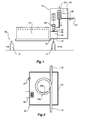
- FIG. 1 shows a bottling line 10 for filling bottles 12 with a product such as wine.
- each bottle 12 passes under a filling station 14 whereat the bottle 12 is charged with a liquid such as wine.
- Each filled bottle 12 then passes under an outlet nozzle 16 of an inerting apparatus 18.
- the inerting apparatus 18 delivers an amount or charge of inerting compound into the head space of the filled bottle 12.
- the inerting apparatus 18 delivers an amount of solid phase CO 2 (hereinafter referred to as CO 2 snow) into the head space of the bottle 12.
- CO 2 snow solid phase CO 2
- a small amount of gaseous CO 2 may also be delivered into the head space of the bottle 12.
- the inerting apparatus 18 includes a fluid pathway 20 having an inlet 22 arranged to be connected to a supply of liquid CO 2 (not shown).
- the supply of liquid CO 2 may be contained in either a portable or static bulk vessel with an operating pressure typically of 1500kPa. Fluid flows from the inlet 22 to a gas eliminator 24 which vents to atmosphere.
- the gas eliminator 24 feeds almost pure liquid CO 2 to a solenoid valve 26 and expansion orifice 28.
- the CO 2 snow and gas exiting from the expansion orifice 28 then pass through a device 30, hereafter referred to as a venting apparatus 30.
- a venting apparatus 30 as much of the CO 2 gas as possible is vented from the pathway 20 so that the inert compound delivered through the outlet nozzle 16 to the head space of the bottle 12 is mostly of a solid phase (i.e. CO 2 snow).
- the proportion of CO 2 snow produced depends on the initial temperature of the liquid CO 2 entering the solenoid valve 26 and expansion orifice 28. The colder the liquid CO 2 , the greater the proportion of CO 2 snow produced. For example, liquid CO 2 at a temperature of -16.8° C produces about 46% of its weight as snow, whilst liquid CO 2 at a temperature of -46.3° C produces about 56% of its weight as snow.
- the heater 29 enables control of the temperature of the liquid CO 2 and thus, as mentioned above, the proportion of CO 2 snow produced.
- the operation of the solenoid valve 26, which determines the timing and quantity of the CO 2 snow delivered to the expansion orifice 28 and thus the bottle 12, is controlled by a sensor 32 and a control system 33.
- the control system 33 may include a PLC.
- the senor 32 is located adjacent the inerting apparatus 18 and is in the form of an optical sensor.
- the sensor 32 activates the control system 33 allowing CO 2 snow to be delivered to the head space of the bottle 12.
- the control system 33 enables four individual injection times and consequently four different CO 2 snow quantities.
- the preferred injection times are 0.04 seconds delivering 0.38 grams of snow, 0.06 seconds delivering 0.57 grams of snow, 0.08 delivering 0.76 grams of snow and 0.10 seconds delivering 0.95 grams of snow to the head space of the bottle 12.
- the control system 33 can also be set for continuous operation.
- the control system 33 also controls the temperature of the heater 29.
- the venting apparatus 30 includes a stainless steel enclosure 34 that is vented to allow for the dispersion of gaseous CO 2 .
- a portion of the pathway 20 that has a tortuous section 20a.
- the tortuous section 20a takes the form of a circular shaped loop.
- the pathway 20 is made from stainless steel tube having a 10mm inner diameter and the circular shaped loop has a diameter of 150mm.
- the diameter of the loop of this embodiment is 150mm, it is envisaged that a diameter of between 100 and 250mm could be effective.
- the diameter of the loop is constrained by size limitations of the inerting apparatus 18 and also by the desired ratio of CO 2 snow/CO 2 gas at the outlet nozzle 16. It is normally preferable to have the highest level of CO 2 snow possible, but it is recognised that a small quantity of CO 2 gas will normally be present at the outlet nozzle 16.
- the curved section or loop 20a of the pathway 20 includes a venting means 20b.
- the venting means 20b includes as a slot 20b cut or formed in an inner wall portion of the loop 20a.
- the slot 20b is positioned and sized so that CO 2 gas can pass from the loop 20a through the vent 20b and then out to atmosphere.
- the slot which forms the vent 20b extends over an arc of approximately 65°.
- the slot has a width of approximately 5.5mm.
- the loop 20a causes the CO 2 snow to follow the outer side of the loop radius, whilst the gas follows the inner side of the loop radius.
- the gaseous CO 2 is separated from the CO 2 snow and can more efficiently vent through the slot 20b.
- the gaseous CO 2 flows out of the slot 20b as the CO 2 snow is pushed through the pathway 20 to the outlet nozzle 16.
- the gaseous CO 2 flows out of the venting apparatus 30 via a vent 35.
- the flow of CO 2 snow meanwhile continues around the loop 20a and arrives at the outlet nozzle 16 at a greatly reduced velocity.
- the velocity of the CO 2 snow is reduced because of the pressure drop at the slot 20b and also because of the diameter and shape of the loop 20a (i.e. the inclusion of the tortuous section 20a). Accordingly, the CO 2 snow can be delivered to the head space of the bottle 12 at a lower velocity. This is advantageous because it increases the efficiency of the CO 2 snow in displacing the air out of the head space of the bottle 12.
- the CO 2 snow is also delivered in a more "compact” form and thus the dosage to the head space of the bottle 12 can be more accurately controlled.
- the "compact" form of the CO 2 snow is important so as to prevent the snow injection angle into the bottle 12 from being too large. If the snow injection angle is too large, snow will be spilled over both sides of the neck of the bottle 12. This is wasteful and more importantly prevents accurate dosing of the head space of the bottle 12.
- Precise control of the amount of CO 2 snow delivered to the head space of the bottle 12 is desirable as it enables the amount of air/oxygen left in the head space after capping to be controlled. Thus, the level of gaseous or dissolved oxygen in the product in the bottle 12 can be maintained at a predetermined level.
- venting means 20b may not remove all of the gaseous CO 2 and that accordingly some gas will be flow out of the outlet 16. However, the amount of gas will be greatly reduced as compared to the amount of gas in the mixture entering the venting apparatus 30. Thus, the inclusion of the vent 20b increases the efficiency and accuracy of the CO 2 snow delivery to the head space of the bottle 12.
- the atmosphere within the enclosure 34 is heated by an air heater 36 that is controlled by the control system 33.
- the enclosure atmosphere is heated to prevent blockages in the section of the pathway 20 within the enclosure 34 and to also prevent blockage of the vent 20b.
- a reducing union may be located between the inlet 22 and the gas eliminator 24.
- a relief valve may also be provided to relieve excess pressure within the pathway 20.
- the components of the inerting apparatus 18 are contained within an enclosure which is preferably made of stainless steel.
- the enclosure may be free standing or suitable for mounting on a wall surface, floor or stand.
- the described embodiment of the invention delivers the CO 2 snow to the outlet nozzle 16 at a reduced velocity. Additionally, because of the inclusion of the vent 20b, a higher proportion of CO 2 snow is delivered to the outlet nozzle 16, thereby making dosing of the head space of the bottle 12 more accurate.
- the inerting apparatus 18 is also suitable for use on high speed bottling lines.
- the invention may be used in conjunction with storage vessels, cans, cartons etc for many different liquids.
- the invention may also be used in connection with empty containers, such as empty bottles or cans (i.e. can be used pre fill or post fill).
- the described embodiment includes a tortuous section 20a which takes the form of a circular loop 20a.
- the tortuous section 20a may adopt different forms.
- other shaped paths may result in a decrease in the velocity of the solid phase inert compound passing there through.
- a path with barriers or protrusions extending from the inner walls of the path may also serve to decrease the velocity of the solid phase inert compound.
- vent 20b is described as a slot.
- the vent may adopt other forms.
- the vent may take the form of a scoop (i.e. an angled and curved protuberance extending inside of the loop).
Landscapes
- Chemical & Material Sciences (AREA)
- Dispersion Chemistry (AREA)
- Engineering & Computer Science (AREA)
- Mechanical Engineering (AREA)
- Filling Of Jars Or Cans And Processes For Cleaning And Sealing Jars (AREA)
- Vacuum Packaging (AREA)
- Feeding, Discharge, Calcimining, Fusing, And Gas-Generation Devices (AREA)
Description
- This invention relates to a method and apparatus for producing an inert atmosphere above a product stored in a container. The invention is particularly applicable in the food industry where contact with atmospheric oxygen may cause deterioration of a food product. However, the invention is not limited to this particular field of use.
- Many liquid products and particularly beverages are susceptible to damage or deterioration when mixed with or exposed to gaseous oxygen (usually oxygen present in air) for a period of time. Some O2 may dissolve in the liquid and react with one or more of the chemical constituents causing undesirable changes such as flavour deterioration, aroma deterioration, colour change, formation of undesirable colour, hazing, browning and so on.
- These changes are of particular concern to the beverage industries producing beer, wines, soft drinks, fruit juices, etc. The quantity of dissolved O2 required to produce a slight but noticeable flavour deterioration in certain types of beer, wines and soft drinks can be extremely small, of the order of 1 ppm or less.
- It is therefore of great importance to exclude or keep to an absolute minimum the presence of O2 (air) in the system during the manufacture, storage, pumping, bottling or canning of many types of these beverages.
- This is generally achieved by the use of a relatively inert and inexpensive gas such as nitrogen (N2) or carbon dioxide (CO2) or even Argon (Ar) to purge items of equipment, storage tanks, pipelines, canning and bottling lines free of air and to then blanket the liquid product to exclude contact with air during manufacture, storage and packaging.
- The choice of whether to use N2 or CO2 or a mixture of these two gases can depend on various factors including the compatibility of the gas with the product, solubility, effect on flavour, taste, aroma or bouquet, storage life, etc. For example, N2 may be the gas preferred for inerting types of wine, whilst CO2 is usually preferred to inerting the gas space in vessels for carbonated beverages such as beer, soft drinks and various types of wine.
- With respect to the use of CO2 in the wine industry for purging equipment including storage tanks and for blanketing the wine during its manufacture, storage and bottling or canning, one practice is to use the CO2 in gaseous form at around room temperature and at or above atmospheric pressure. The CO2 gas may be obtained from transportable high pressure liquid CO2 containers or by vapourising liquid CO2 stored in on-site storage vessels operating at pressures ranging from about 650 kPa to about 2100 kPa.
- Because the density of gaseous CO2 at room temperature and at atmospheric pressure is about 50% greater than that of air under the same conditions, it has proved to be very suitable for displacing air from empty wine storage tanks prior to filling and for eliminating or greatly minimising the ingress of air during static storage and during the emptying of these tanks. Also, it is being used on a large scale to displace the air from empty wine bottles and cans prior to filling.
- Australian patent 580732 describes methods and apparatus for producing an inert atmosphere above a stored product in a storage vessel. More particularly, Australian patent 580732 describes an apparatus and method for delivering a mixture of CO2 snow and gaseous CO2 into the head space of a recently filled bottle. The gaseous CO2 which is heavier than the air in the head space displaces the air from the bottle. Additionally, the CO2 gas resulting from the sublimation of the CO2 snow in the relatively warm bottle displaces any remaining air and then flows gently out of the neck of the bottle, thus preventing air from re-entering the bottle. In this manner the air/oxygen content of the head space at the capping or corking station is significantly reduced when compared to bottles capped following the introduction of only gaseous CO2 into the head space of the bottle.
- Although the method and apparatus disclosed in Australian patent 580732 offers some advantage over prior art arrangements, the present invention seeks to further improve thereon.
- The discussion of the background to the invention herein is included to explain the context of the invention. This is not to be taken as an admission that any of the material referred to was published, known or part of the common general knowledge as at the priority date of any of the claims.
- According to a first aspect of the present invention there is provided a device for supplying an inert compound into the head space of a container, the device including a delivery path having an inlet for receiving a mixture of gaseous and solid phase inert compound, an outlet and a tortuous section located between said inlet and said outlet, said tortuous section being arranged to reduce the velocity of said solid phase inert compound as it flows there through.
- Preferably, a vent means is formed in the tortuous section so that gaseous phase inert compound can vent from the tortuous section.
- The tortuous section may adopt many different forms. However, in one preferred form, the tortuous section includes a curved section, for example a loop, through which the inert compound flows. The loop is preferably substantially circular in shape. In such an embodiment, the venting means may include a vent or slot formed in an inner side thereof.
- The tortuous section is preferably shaped so that the gaseous phase inert compound is separated from the solid phase inert compound as it travels there through so that the gaseous phase inert compound can be more readily vented through the venting means.
- Preferably, the inert compound delivered from said outlet is of a substantially solid phase.
- According to a second aspect of the present invention there is provided an apparatus for supplying an inert compound into an head space of a container, said apparatus including a pathway having an inlet arranged to be connected to a supply of an inert compound in a liquid phase, means for converting said inert compound from a liquid phase to a mixture of solid and gaseous phase inert compound and an outlet arranged to supply inert compound to the head space of the container and wherein a device is provided substantially adjacent the outlet, said device including a delivery path having an inlet for receiving the mixture of solid and gaseous phase inert compound, an outlet and a tortuous section located between said inlet and said outlet, said tortuous section being arranged to reduce the velocity of said solid phase inert compound as it flows there through.
- According to a third aspect of the present invention there is provided a method of storing a liquid in a container, said method including the steps of:
- (i)
- partially filling a container with a liquid so that a head space filled with air is formed in an upper part of the container;
- (ii)
- passing an amount of an inert compound through a converting means to convert the inert compound to a mixture of a solid and a gaseous state;
- (iii)
- passing the mixture through a device including a delivery path having an inlet for receiving a mixture of gaseous and solid phase inert compound, an outlet and a tortuous section located between said inlet and said outlet, said tortuous section being arranged to reduce the velocity of said solid phase inert compound as it flows there through; and
- (iv)
- delivering inert compound into the head space of the container.
- Preferably, a closure is applied to the container after air and in particular after oxygen has been displaced from the head space. The air and/or oxygen is preferably displaced from the head space as a result of sublimation of the inert compound. Accordingly, the inert compound is denser than air and/or oxygen when the solid phase inert compound has returned to the gaseous phase after sublimation and is at a lower temperature than the ambient air.
- The invention further includes a bottling line incorporating an apparatus according to the second aspect of the present invention.
- As used throughout this specification, the phrase "inert compound" is used to define any substance that is in gaseous form at atmospheric pressure and at a temperature above 0° C and which does not react to an unacceptable degree with the other components in the container.
- The inert compound delivered is preferably denser than air, at least when the inert compound has returned to the gaseous phase after sublimation. The greater density of the inert compound may be an intrinsic property of the gas (i.e. at atmospheric pressure and temperature the deposited gas has a greater density than air). Alternatively, or in addition, the greater density of the inert compound may be a result of the low temperature thereof after sublimation (i.e. the gas has a greater density then air at the temperature at which it sublimes). The use of an inert compound denser than air enables the method and apparatus of the present invention to be used to create a layer of inert gas above the surface of the liquid in the container, said layer of gas serving to displace any air/oxygen from the head space of the container. This layer is preferably relatively stable and arranged to remain as an effective inerting atmosphere at the liquid surface for a considerable period of time.
- The preferred inert compound for many possible applications of the invention is carbon dioxide (CO2). Carbon dioxide is denser than air when it is in the gaseous phase at standard temperature and pressure. Thus, it will create a layer of an inert gas at the liquid surface due to the density difference. The carbon dioxide is preferably deposited in the head space of the container as solid phase carbon dioxide (CO2 snow) at about -78.5°. However, it will be appreciated by those skilled in the art that at least a small amount of gaseous carbon dioxide will also be delivered into the head space of the container.
- Embodiments of the invention will now be described, by way of example only, with reference to the accompanying drawings in which:
- Figure 1 is a schematic side view of an apparatus according to an embodiment of the invention; and
- Figure 2 is a schematic front view of a venting apparatus according to an embodiment of the invention.
- Figure 1 shows a
bottling line 10 for fillingbottles 12 with a product such as wine. As shown in this Figure, eachbottle 12 passes under a fillingstation 14 whereat thebottle 12 is charged with a liquid such as wine. Each filledbottle 12 then passes under anoutlet nozzle 16 of aninerting apparatus 18. Theinerting apparatus 18 delivers an amount or charge of inerting compound into the head space of the filledbottle 12. In this embodiment, theinerting apparatus 18 delivers an amount of solid phase CO2 (hereinafter referred to as CO2 snow) into the head space of thebottle 12. A small amount of gaseous CO2 may also be delivered into the head space of thebottle 12. As the CO2 snow settles and/or comes into contact with the wine in thebottle 12, sublimation takes place causing displacement from the head space of thebottle 12 of air/oxygen. The resulting cold dense CO2 gas then acts to prevent any substantial reintroduction of air/oxygen into the headspace of thebottle 12 prior to capping at a capping station (not shown). Preferably, sublimation of the CO2 snow is almost completed by the time the cap/closure is applied to thebottle 12. - The
inerting apparatus 18 includes afluid pathway 20 having aninlet 22 arranged to be connected to a supply of liquid CO2 (not shown). The supply of liquid CO2 may be contained in either a portable or static bulk vessel with an operating pressure typically of 1500kPa. Fluid flows from theinlet 22 to agas eliminator 24 which vents to atmosphere. Thegas eliminator 24 feeds almost pure liquid CO2 to asolenoid valve 26 and expansion orifice 28. The CO2 snow and gas exiting from the expansion orifice 28 then pass through adevice 30, hereafter referred to as a ventingapparatus 30. In theventing apparatus 30 as much of the CO2 gas as possible is vented from thepathway 20 so that the inert compound delivered through theoutlet nozzle 16 to the head space of thebottle 12 is mostly of a solid phase (i.e. CO2 snow). - The proportion of CO2 snow produced depends on the initial temperature of the liquid CO2 entering the
solenoid valve 26 and expansion orifice 28. The colder the liquid CO2, the greater the proportion of CO2 snow produced. For example, liquid CO2 at a temperature of -16.8° C produces about 46% of its weight as snow, whilst liquid CO2 at a temperature of -46.3° C produces about 56% of its weight as snow. - A
heater 29, for example a band heater, is provided on or adjacent to thesolenoid valve 26 so as to enable control of the temperature of thevalve 26. - The
heater 29 enables control of the temperature of the liquid CO2 and thus, as mentioned above, the proportion of CO2 snow produced. - The operation of the
solenoid valve 26, which determines the timing and quantity of the CO2 snow delivered to the expansion orifice 28 and thus thebottle 12, is controlled by asensor 32 and acontrol system 33. Thecontrol system 33 may include a PLC. - In the illustrated embodiment, the
sensor 32 is located adjacent theinerting apparatus 18 and is in the form of an optical sensor. Thesensor 32 activates thecontrol system 33 allowing CO2 snow to be delivered to the head space of thebottle 12. In a preferred embodiment of the invention, thecontrol system 33 enables four individual injection times and consequently four different CO2 snow quantities. The preferred injection times are 0.04 seconds delivering 0.38 grams of snow, 0.06 seconds delivering 0.57 grams of snow, 0.08 delivering 0.76 grams of snow and 0.10 seconds delivering 0.95 grams of snow to the head space of thebottle 12. Thecontrol system 33 can also be set for continuous operation. Thecontrol system 33 also controls the temperature of theheater 29. - The venting
apparatus 30 includes astainless steel enclosure 34 that is vented to allow for the dispersion of gaseous CO2. Housed within theenclosure 34 is a portion of thepathway 20 that has atortuous section 20a. As best shown in Figure 2, thetortuous section 20a takes the form of a circular shaped loop. In accordance with one preferred embodiment of the invention, thepathway 20 is made from stainless steel tube having a 10mm inner diameter and the circular shaped loop has a diameter of 150mm. Although the diameter of the loop of this embodiment is 150mm, it is envisaged that a diameter of between 100 and 250mm could be effective. The diameter of the loop is constrained by size limitations of theinerting apparatus 18 and also by the desired ratio of CO2 snow/CO2 gas at theoutlet nozzle 16. It is normally preferable to have the highest level of CO2 snow possible, but it is recognised that a small quantity of CO2 gas will normally be present at theoutlet nozzle 16. - As best depicted in Figure 2, the curved section or
loop 20a of thepathway 20 includes a venting means 20b. The venting means 20b includes as aslot 20b cut or formed in an inner wall portion of theloop 20a. Theslot 20b is positioned and sized so that CO2 gas can pass from theloop 20a through thevent 20b and then out to atmosphere. In accordance with one preferred embodiment of the invention wherein the loop has a diameter of 100mm, the slot which forms thevent 20b extends over an arc of approximately 65°. The slot has a width of approximately 5.5mm. - The
loop 20a causes the CO2 snow to follow the outer side of the loop radius, whilst the gas follows the inner side of the loop radius. Thus, the gaseous CO2 is separated from the CO2 snow and can more efficiently vent through theslot 20b. - Most of the gaseous CO2 flows out of the
slot 20b as the CO2 snow is pushed through thepathway 20 to theoutlet nozzle 16. The gaseous CO2 flows out of the ventingapparatus 30 via a vent 35. The flow of CO2 snow meanwhile continues around theloop 20a and arrives at theoutlet nozzle 16 at a greatly reduced velocity. The velocity of the CO2 snow is reduced because of the pressure drop at theslot 20b and also because of the diameter and shape of theloop 20a (i.e. the inclusion of thetortuous section 20a). Accordingly, the CO2 snow can be delivered to the head space of thebottle 12 at a lower velocity. This is advantageous because it increases the efficiency of the CO2 snow in displacing the air out of the head space of thebottle 12. - The CO2 snow is also delivered in a more "compact" form and thus the dosage to the head space of the
bottle 12 can be more accurately controlled. The "compact" form of the CO2 snow is important so as to prevent the snow injection angle into thebottle 12 from being too large. If the snow injection angle is too large, snow will be spilled over both sides of the neck of thebottle 12. This is wasteful and more importantly prevents accurate dosing of the head space of thebottle 12. Precise control of the amount of CO2 snow delivered to the head space of thebottle 12 is desirable as it enables the amount of air/oxygen left in the head space after capping to be controlled. Thus, the level of gaseous or dissolved oxygen in the product in thebottle 12 can be maintained at a predetermined level. - It will be appreciated that the venting means 20b may not remove all of the gaseous CO2 and that accordingly some gas will be flow out of the
outlet 16. However, the amount of gas will be greatly reduced as compared to the amount of gas in the mixture entering the ventingapparatus 30. Thus, the inclusion of thevent 20b increases the efficiency and accuracy of the CO2 snow delivery to the head space of thebottle 12. - The atmosphere within the
enclosure 34 is heated by anair heater 36 that is controlled by thecontrol system 33. The enclosure atmosphere is heated to prevent blockages in the section of thepathway 20 within theenclosure 34 and to also prevent blockage of thevent 20b. - Although not illustrated in the Figures, a reducing union may be located between the
inlet 22 and thegas eliminator 24. A relief valve may also be provided to relieve excess pressure within thepathway 20. - The components of the
inerting apparatus 18 are contained within an enclosure which is preferably made of stainless steel. The enclosure may be free standing or suitable for mounting on a wall surface, floor or stand. - The described embodiment of the invention delivers the CO2 snow to the
outlet nozzle 16 at a reduced velocity. Additionally, because of the inclusion of thevent 20b, a higher proportion of CO2 snow is delivered to theoutlet nozzle 16, thereby making dosing of the head space of thebottle 12 more accurate. Theinerting apparatus 18 is also suitable for use on high speed bottling lines. - Although the embodiment of the invention has been described in relation to filled containers, such as wine bottles, it will be appreciated that the invention is not restricted to such applications. The invention may be used in conjunction with storage vessels, cans, cartons etc for many different liquids. The invention may also be used in connection with empty containers, such as empty bottles or cans (i.e. can be used pre fill or post fill).
- The described embodiment includes a
tortuous section 20a which takes the form of acircular loop 20a. However, it is recognised that thetortuous section 20a may adopt different forms. For example, it is envisaged that other shaped paths may result in a decrease in the velocity of the solid phase inert compound passing there through. It is also envisaged that a path with barriers or protrusions extending from the inner walls of the path may also serve to decrease the velocity of the solid phase inert compound. - In the present embodiment the
vent 20b is described as a slot. However, it will be appreciated by those skilled in the art that the vent may adopt other forms. For example, the vent may take the form of a scoop (i.e. an angled and curved protuberance extending inside of the loop). - The embodiments have been described by way of example only and modifications within the scope of the invention are envisaged.
Claims (17)
- A device (30) for supplying an inert compound into the head space of a container (12), the device (30) including a delivery path having an inlet for receiving a mixture of gaseous and solid phase inert compound, an outlet (16) and a tortuous section (20a) located between said inlet and said outlet, said tortuous section being arranged to reduce the velocity of said solid phase inert compound as it flows there through.
- A device according to claim 1 wherein the tortuous section (20a) includes a curved section through which the inert compound flows.
- A device according to claim 2 wherein the curved section forms a loop.
- A device according to claim 3 wherein the loop is substantially circular.
- A device according to any one of the preceding claims including a vent means (20b) formed in the tortuous section, the vent means being arranged so that gaseous phase inert compound can vent from the tortuous section.
- A device according to claim 5 wherein the venting means (20b) includes a vent or slot formed in an inner side of the tortuous section (20a).
- A device according to claim 5 wherein the tortuous section (20a) is formed as a circular loop and the venting means (20b) is formed in the inner side of the loop radius.
- A device according to claim 7 wherein the loop has a dimeter of about 100mm to 250mm.
- A device according to claim 8 wherein the venting means (20b) extends over an arc of the loop of approximately 65°.
- A device according to claim 8 or claim 9 wherein the venting means (20b) is formed as a slot.
- A device according to claim 10 wherein the slot has a width of approximately 5.5mm.
- An apparatus (18) for supplying an inert compound into an head space of a container (12), said apparatus including a pathway (20) having an inlet (22) arranged to be connected to a supply of an inert compound in a liquid phase, means (26,28) for converting said inert compound from a liquid phase to a mixture of solid and gaseous phase inert compound and an outlet arranged to supply inert compound to the head space of the container and wherein a device according to claim 1 is provided substantially adjacent the outlet.
- An apparatus according to claim 12 wherein said device is according to any one of claims 2 to 11.
- A bottling line including an apparatus according to claim 12 or claim 13.
- A bottling line according to claim 14 further including a sensor (32) and a control system (33) for controlling the apparatus (18), said sensor (32) being arranged to activate the control system (33) so that said inert compound is delivered to the head space of a container (12) on the bottling line.
- A method of storing a liquid in a container, said method including the steps of:(i) partially filling a container (12) with a liquid so that a head space filled with air is formed in an upper part of the container;(ii) passing an amount of an inert compound through a converting means (26,28) to convert the inert compound to a mixture of a solid and a gaseous state;(iii) passing the mixture through a device (30) including a delivery path having an inlet for receiving a mixture of gaseous and solid phase inert compound, an outlet (16) and a tortuous section (20a) located between said inlet and said outlet (16), said tortuous section (20a) being arranged to reduce the velocity of said solid phase inert compound as it flows there through; and(iv) delivering inert compound into the head space of the container (12).
- A method according to claim 16 including the step of applying a closure to the container (12) after air and/or oxygen has been displaced from the head space of the container.
Applications Claiming Priority (4)
| Application Number | Priority Date | Filing Date | Title |
|---|---|---|---|
| AU2004903403P | 2004-06-21 | ||
| AU2004903403A AU2004903403A0 (en) | 2004-06-21 | An Apparatus for Inerting the Headspace of a Container | |
| AU2005202150A AU2005202150A1 (en) | 2004-06-21 | 2005-05-19 | An Apparatus for Inerting the Headspace of a Container |
| AU2005202150 | 2005-05-19 |
Publications (4)
| Publication Number | Publication Date |
|---|---|
| EP1609721A1 EP1609721A1 (en) | 2005-12-28 |
| EP1609721B1 true EP1609721B1 (en) | 2007-03-14 |
| EP1609721B8 EP1609721B8 (en) | 2007-09-12 |
| EP1609721B9 EP1609721B9 (en) | 2007-10-31 |
Family
ID=34940176
Family Applications (1)
| Application Number | Title | Priority Date | Filing Date |
|---|---|---|---|
| EP05105255A Expired - Lifetime EP1609721B9 (en) | 2004-06-21 | 2005-06-15 | An apparatus for inerting the headspace of a container |
Country Status (9)
| Country | Link |
|---|---|
| US (1) | US20060000518A1 (en) |
| EP (1) | EP1609721B9 (en) |
| AR (1) | AR049359A1 (en) |
| AT (1) | ATE356750T1 (en) |
| AU (1) | AU2005202150A1 (en) |
| CA (1) | CA2510082A1 (en) |
| DE (1) | DE602005000706T2 (en) |
| ES (1) | ES2284130T3 (en) |
| PT (1) | PT1609721E (en) |
Cited By (1)
| Publication number | Priority date | Publication date | Assignee | Title |
|---|---|---|---|---|
| WO2014060320A1 (en) | 2012-10-15 | 2014-04-24 | V.B.S. | Carbon dioxide dosing apparatus |
Families Citing this family (7)
| Publication number | Priority date | Publication date | Assignee | Title |
|---|---|---|---|---|
| GB0816310D0 (en) | 2008-09-05 | 2008-10-15 | Mtt Technologies Ltd | Filter assembly |
| DE102010044244A1 (en) * | 2010-09-02 | 2012-03-08 | Khs Gmbh | Method and device for treating containers |
| DE102011106760A1 (en) * | 2011-07-05 | 2013-01-10 | Khs Gmbh | Method and linear system for filling containers with a product |
| US9661872B2 (en) * | 2012-10-17 | 2017-05-30 | Pepsico, Inc. | Post fill carbonation with container overpressure limitation |
| DE102013103192A1 (en) * | 2013-03-28 | 2014-10-02 | Khs Gmbh | Method and filling system for filling containers |
| WO2015000697A1 (en) * | 2013-07-03 | 2015-01-08 | Nomacorc Llc | Apparatus, method and system for reducing the oxygen content in a product container |
| JP2017538038A (en) * | 2014-11-21 | 2017-12-21 | レニショウ パブリック リミテッド カンパニーRenishaw Public Limited Company | Additive manufacturing apparatus and method |
Family Cites Families (7)
| Publication number | Priority date | Publication date | Assignee | Title |
|---|---|---|---|---|
| US2297190A (en) * | 1939-10-11 | 1942-09-29 | Ronald B Mckinnis | Apparatus for packaging liquids |
| US2536322A (en) * | 1945-06-23 | 1951-01-02 | Jessie F Smith | Transfer and recovery system for volatile liquids |
| US4098305A (en) * | 1976-03-18 | 1978-07-04 | Manning Environmental Corporation | Continuing liquid sampling apparatus and method |
| SE446826B (en) * | 1981-04-24 | 1986-10-13 | Icab Ind Coating Ab | POWDER SPRAY WITH ELECTROSTATIC CHARGING FORM CONSISTING OF LONG-TERM CROCHET CHARGING CHANNELS WHICH ARE CROSSED TO IMAGE LOOP OR CARS ORGANIZED IN A MULTIPLE GROUPS |
| AU580732B2 (en) * | 1983-04-06 | 1989-02-02 | Air Liquide Australia Limited | Inerting storage vessel gas space |
| GB8928893D0 (en) * | 1989-12-21 | 1990-02-28 | Whitbread & Co Plc | Carbonated beverage container |
| AU3344199A (en) * | 1998-04-17 | 1999-11-08 | Toyo Seikan Kaisha Ltd. | Method and device for manufacturing positive pressure packaging body |
-
2005
- 2005-05-19 AU AU2005202150A patent/AU2005202150A1/en not_active Abandoned
- 2005-06-15 DE DE602005000706T patent/DE602005000706T2/en not_active Expired - Fee Related
- 2005-06-15 ES ES05105255T patent/ES2284130T3/en not_active Expired - Lifetime
- 2005-06-15 PT PT05105255T patent/PT1609721E/en unknown
- 2005-06-15 EP EP05105255A patent/EP1609721B9/en not_active Expired - Lifetime
- 2005-06-15 AT AT05105255T patent/ATE356750T1/en not_active IP Right Cessation
- 2005-06-15 CA CA002510082A patent/CA2510082A1/en not_active Abandoned
- 2005-06-17 AR ARP050102518A patent/AR049359A1/en active IP Right Grant
- 2005-09-07 US US11/158,182 patent/US20060000518A1/en not_active Abandoned
Cited By (1)
| Publication number | Priority date | Publication date | Assignee | Title |
|---|---|---|---|---|
| WO2014060320A1 (en) | 2012-10-15 | 2014-04-24 | V.B.S. | Carbon dioxide dosing apparatus |
Also Published As
| Publication number | Publication date |
|---|---|
| EP1609721A1 (en) | 2005-12-28 |
| EP1609721B9 (en) | 2007-10-31 |
| CA2510082A1 (en) | 2005-12-21 |
| ES2284130T3 (en) | 2007-11-01 |
| EP1609721B8 (en) | 2007-09-12 |
| AU2005202150A1 (en) | 2006-01-12 |
| AR049359A1 (en) | 2006-07-19 |
| DE602005000706D1 (en) | 2007-04-26 |
| ATE356750T1 (en) | 2007-04-15 |
| US20060000518A1 (en) | 2006-01-05 |
| DE602005000706T2 (en) | 2007-12-06 |
| PT1609721E (en) | 2007-06-25 |
Similar Documents
| Publication | Publication Date | Title |
|---|---|---|
| US4347695A (en) | Beverage bottling method | |
| RU2391878C2 (en) | Method and device for puring of oxygen-enriched air liquids | |
| CA3031814C (en) | System and method for deaerating beverages | |
| EP0421597A1 (en) | A liquid dispensing system and packaging apparatus which includes such a system | |
| EP1609721B9 (en) | An apparatus for inerting the headspace of a container | |
| US4835937A (en) | Apparatus for providing inert atmosphere in airtight packages for food products | |
| US4870801A (en) | Process and apparatus for making an inert atmosphere in airtight packages | |
| US4977723A (en) | Plant for packing products in containers | |
| EP0489589A1 (en) | Dissolving a gas in a liquid | |
| GB2330761A (en) | Treatment of wine with argon | |
| US20060144017A1 (en) | Method and apparatus for inerting head space of a capped container | |
| NZ263220A (en) | Canning line bypass for purging oxygen from head inducer capsule and filling with suitable gas and liquid ahead of filling and seaming | |
| US7080670B1 (en) | Method and device for filling a drinks container with a drink produced from an initial liquid, and corresponding drink container | |
| GB2288794A (en) | Flow control tube for carbonated beverage container | |
| ZA200504998B (en) | An apparatus for interting the headspace of a container | |
| EP0447103A1 (en) | Dissolving gas in a liquid | |
| US20060010886A1 (en) | Liquid cryogen dosing system with nozzle for pressurizing and inerting containers | |
| GB2092552A (en) | Dispensing apparatus | |
| EP0008886A1 (en) | Method and apparatus for manufacturing packaged beverages and packages manufactured by such method | |
| JP3083107B2 (en) | Method for producing bottled beverage and apparatus used therefor | |
| EP2906497B1 (en) | Carbon dioxide dosing apparatus | |
| EP0827936A1 (en) | A process and a device for headspace inertization of bottles filled with carbonated beverages | |
| JPS6352865A (en) | Manufacturing method for gas-filled canned goods | |
| HK40021331A (en) | Wine bottle and method | |
| SK4182001A3 (en) | Method and device for inerting headspaces |
Legal Events
| Date | Code | Title | Description |
|---|---|---|---|
| PUAI | Public reference made under article 153(3) epc to a published international application that has entered the european phase |
Free format text: ORIGINAL CODE: 0009012 |
|
| AK | Designated contracting states |
Kind code of ref document: A1 Designated state(s): AT BE BG CH CY CZ DE DK EE ES FI FR GB GR HU IE IS IT LI LT LU MC NL PL PT RO SE SI SK TR |
|
| AX | Request for extension of the european patent |
Extension state: AL BA HR LV MK YU |
|
| 17P | Request for examination filed |
Effective date: 20060628 |
|
| GRAP | Despatch of communication of intention to grant a patent |
Free format text: ORIGINAL CODE: EPIDOSNIGR1 |
|
| AKX | Designation fees paid |
Designated state(s): AT BE BG CH CY CZ DE DK EE ES FI FR GB GR HU IE IS IT LI LT LU MC NL PL PT RO SE SI SK TR |
|
| GRAS | Grant fee paid |
Free format text: ORIGINAL CODE: EPIDOSNIGR3 |
|
| GRAA | (expected) grant |
Free format text: ORIGINAL CODE: 0009210 |
|
| AK | Designated contracting states |
Kind code of ref document: B1 Designated state(s): AT BE BG CH CY CZ DE DK EE ES FI FR GB GR HU IE IS IT LI LT LU MC NL PL PT RO SE SI SK TR |
|
| PG25 | Lapsed in a contracting state [announced via postgrant information from national office to epo] |
Ref country code: AT Free format text: LAPSE BECAUSE OF FAILURE TO SUBMIT A TRANSLATION OF THE DESCRIPTION OR TO PAY THE FEE WITHIN THE PRESCRIBED TIME-LIMIT Effective date: 20070314 Ref country code: CH Free format text: LAPSE BECAUSE OF FAILURE TO SUBMIT A TRANSLATION OF THE DESCRIPTION OR TO PAY THE FEE WITHIN THE PRESCRIBED TIME-LIMIT Effective date: 20070314 Ref country code: SI Free format text: LAPSE BECAUSE OF FAILURE TO SUBMIT A TRANSLATION OF THE DESCRIPTION OR TO PAY THE FEE WITHIN THE PRESCRIBED TIME-LIMIT Effective date: 20070314 Ref country code: LI Free format text: LAPSE BECAUSE OF FAILURE TO SUBMIT A TRANSLATION OF THE DESCRIPTION OR TO PAY THE FEE WITHIN THE PRESCRIBED TIME-LIMIT Effective date: 20070314 Ref country code: FI Free format text: LAPSE BECAUSE OF FAILURE TO SUBMIT A TRANSLATION OF THE DESCRIPTION OR TO PAY THE FEE WITHIN THE PRESCRIBED TIME-LIMIT Effective date: 20070314 Ref country code: PL Free format text: LAPSE BECAUSE OF FAILURE TO SUBMIT A TRANSLATION OF THE DESCRIPTION OR TO PAY THE FEE WITHIN THE PRESCRIBED TIME-LIMIT Effective date: 20070314 |
|
| REG | Reference to a national code |
Ref country code: GB Ref legal event code: FG4D |
|
| REG | Reference to a national code |
Ref country code: CH Ref legal event code: EP |
|
| RAP2 | Party data changed (patent owner data changed or rights of a patent transferred) |
Owner name: L'AIR LIQUIDE, SOCIETE ANONYME POUR L'ETUDE ET L'E |
|
| REF | Corresponds to: |
Ref document number: 602005000706 Country of ref document: DE Date of ref document: 20070426 Kind code of ref document: P |
|
| REG | Reference to a national code |
Ref country code: IE Ref legal event code: FG4D |
|
| RAP2 | Party data changed (patent owner data changed or rights of a patent transferred) |
Owner name: L'AIR LIQUIDE, SOCIETE ANONYME POUR L'ETUDE ET L'E |
|
| PG25 | Lapsed in a contracting state [announced via postgrant information from national office to epo] |
Ref country code: SE Free format text: LAPSE BECAUSE OF FAILURE TO SUBMIT A TRANSLATION OF THE DESCRIPTION OR TO PAY THE FEE WITHIN THE PRESCRIBED TIME-LIMIT Effective date: 20070614 |
|
| REG | Reference to a national code |
Ref country code: PT Ref legal event code: SC4A Free format text: AVAILABILITY OF NATIONAL TRANSLATION Effective date: 20070612 |
|
| NLT2 | Nl: modifications (of names), taken from the european patent patent bulletin |
Owner name: L'AIR LIQUIDE, SOCIETE ANONYME POUR L'ETUDE Effective date: 20070425 |
|
| PG25 | Lapsed in a contracting state [announced via postgrant information from national office to epo] |
Ref country code: IS Free format text: LAPSE BECAUSE OF FAILURE TO SUBMIT A TRANSLATION OF THE DESCRIPTION OR TO PAY THE FEE WITHIN THE PRESCRIBED TIME-LIMIT Effective date: 20070714 |
|
| NLT2 | Nl: modifications (of names), taken from the european patent patent bulletin |
Owner name: L'AIR LIQUIDE, SOCIETE ANONYME POUR L'ETUDE L'EXPL Effective date: 20070613 |
|
| REG | Reference to a national code |
Ref country code: GB Ref legal event code: ERR Free format text: NOTIFICATION HAS NOW BEEN RECEIVED FROM THE EPO THAT THE CORRECT NAME IS L'AIR LIQUIDE, SOCIETE ANONYME POUR L'ETUDE ET L'EXPLOITATION DES PROCEDES GEORGES CLAUDE THE CORRECTION WAS PUBLISHED IN THE EPO BULLETIN 07/24 DATED 20070613 |
|
| ET | Fr: translation filed | ||
| REG | Reference to a national code |
Ref country code: CH Ref legal event code: PL |
|
| REG | Reference to a national code |
Ref country code: ES Ref legal event code: FG2A Ref document number: 2284130 Country of ref document: ES Kind code of ref document: T3 |
|
| PG25 | Lapsed in a contracting state [announced via postgrant information from national office to epo] |
Ref country code: SK Free format text: LAPSE BECAUSE OF FAILURE TO SUBMIT A TRANSLATION OF THE DESCRIPTION OR TO PAY THE FEE WITHIN THE PRESCRIBED TIME-LIMIT Effective date: 20070314 |
|
| PG25 | Lapsed in a contracting state [announced via postgrant information from national office to epo] |
Ref country code: CZ Free format text: LAPSE BECAUSE OF FAILURE TO SUBMIT A TRANSLATION OF THE DESCRIPTION OR TO PAY THE FEE WITHIN THE PRESCRIBED TIME-LIMIT Effective date: 20070314 Ref country code: RO Free format text: LAPSE BECAUSE OF FAILURE TO SUBMIT A TRANSLATION OF THE DESCRIPTION OR TO PAY THE FEE WITHIN THE PRESCRIBED TIME-LIMIT Effective date: 20070314 |
|
| PLBE | No opposition filed within time limit |
Free format text: ORIGINAL CODE: 0009261 |
|
| STAA | Information on the status of an ep patent application or granted ep patent |
Free format text: STATUS: NO OPPOSITION FILED WITHIN TIME LIMIT |
|
| PG25 | Lapsed in a contracting state [announced via postgrant information from national office to epo] |
Ref country code: MC Free format text: LAPSE BECAUSE OF NON-PAYMENT OF DUE FEES Effective date: 20070630 Ref country code: DK Free format text: LAPSE BECAUSE OF FAILURE TO SUBMIT A TRANSLATION OF THE DESCRIPTION OR TO PAY THE FEE WITHIN THE PRESCRIBED TIME-LIMIT Effective date: 20070314 |
|
| 26N | No opposition filed |
Effective date: 20071217 |
|
| PG25 | Lapsed in a contracting state [announced via postgrant information from national office to epo] |
Ref country code: LT Free format text: LAPSE BECAUSE OF FAILURE TO SUBMIT A TRANSLATION OF THE DESCRIPTION OR TO PAY THE FEE WITHIN THE PRESCRIBED TIME-LIMIT Effective date: 20070314 |
|
| PG25 | Lapsed in a contracting state [announced via postgrant information from national office to epo] |
Ref country code: GR Free format text: LAPSE BECAUSE OF FAILURE TO SUBMIT A TRANSLATION OF THE DESCRIPTION OR TO PAY THE FEE WITHIN THE PRESCRIBED TIME-LIMIT Effective date: 20070615 |
|
| PG25 | Lapsed in a contracting state [announced via postgrant information from national office to epo] |
Ref country code: IE Free format text: LAPSE BECAUSE OF NON-PAYMENT OF DUE FEES Effective date: 20070615 |
|
| PGFP | Annual fee paid to national office [announced via postgrant information from national office to epo] |
Ref country code: ES Payment date: 20080605 Year of fee payment: 4 |
|
| PGFP | Annual fee paid to national office [announced via postgrant information from national office to epo] |
Ref country code: BE Payment date: 20080606 Year of fee payment: 4 Ref country code: PT Payment date: 20080519 Year of fee payment: 4 |
|
| PGFP | Annual fee paid to national office [announced via postgrant information from national office to epo] |
Ref country code: DE Payment date: 20080523 Year of fee payment: 4 Ref country code: NL Payment date: 20080516 Year of fee payment: 4 |
|
| PG25 | Lapsed in a contracting state [announced via postgrant information from national office to epo] |
Ref country code: EE Free format text: LAPSE BECAUSE OF FAILURE TO SUBMIT A TRANSLATION OF THE DESCRIPTION OR TO PAY THE FEE WITHIN THE PRESCRIBED TIME-LIMIT Effective date: 20070314 |
|
| PG25 | Lapsed in a contracting state [announced via postgrant information from national office to epo] |
Ref country code: CY Free format text: LAPSE BECAUSE OF FAILURE TO SUBMIT A TRANSLATION OF THE DESCRIPTION OR TO PAY THE FEE WITHIN THE PRESCRIBED TIME-LIMIT Effective date: 20070314 |
|
| PG25 | Lapsed in a contracting state [announced via postgrant information from national office to epo] |
Ref country code: LU Free format text: LAPSE BECAUSE OF NON-PAYMENT OF DUE FEES Effective date: 20070615 Ref country code: BG Free format text: LAPSE BECAUSE OF FAILURE TO SUBMIT A TRANSLATION OF THE DESCRIPTION OR TO PAY THE FEE WITHIN THE PRESCRIBED TIME-LIMIT Effective date: 20070614 |
|
| PG25 | Lapsed in a contracting state [announced via postgrant information from national office to epo] |
Ref country code: HU Free format text: LAPSE BECAUSE OF FAILURE TO SUBMIT A TRANSLATION OF THE DESCRIPTION OR TO PAY THE FEE WITHIN THE PRESCRIBED TIME-LIMIT Effective date: 20070915 Ref country code: TR Free format text: LAPSE BECAUSE OF FAILURE TO SUBMIT A TRANSLATION OF THE DESCRIPTION OR TO PAY THE FEE WITHIN THE PRESCRIBED TIME-LIMIT Effective date: 20070314 |
|
| REG | Reference to a national code |
Ref country code: PT Ref legal event code: MM4A Free format text: LAPSE DUE TO NON-PAYMENT OF FEES Effective date: 20091215 |
|
| BERE | Be: lapsed |
Owner name: L'AIR LIQUIDE, S.A. POUR L'ETUDE ET L'EXPLOITATIO Effective date: 20090630 |
|
| GBPC | Gb: european patent ceased through non-payment of renewal fee |
Effective date: 20090615 |
|
| NLV4 | Nl: lapsed or anulled due to non-payment of the annual fee |
Effective date: 20100101 |
|
| REG | Reference to a national code |
Ref country code: FR Ref legal event code: ST Effective date: 20100226 |
|
| PG25 | Lapsed in a contracting state [announced via postgrant information from national office to epo] |
Ref country code: PT Free format text: LAPSE BECAUSE OF NON-PAYMENT OF DUE FEES Effective date: 20091215 |
|
| PG25 | Lapsed in a contracting state [announced via postgrant information from national office to epo] |
Ref country code: FR Free format text: LAPSE BECAUSE OF NON-PAYMENT OF DUE FEES Effective date: 20090630 |
|
| PGFP | Annual fee paid to national office [announced via postgrant information from national office to epo] |
Ref country code: FR Payment date: 20080513 Year of fee payment: 4 |
|
| PG25 | Lapsed in a contracting state [announced via postgrant information from national office to epo] |
Ref country code: GB Free format text: LAPSE BECAUSE OF NON-PAYMENT OF DUE FEES Effective date: 20090615 |
|
| PG25 | Lapsed in a contracting state [announced via postgrant information from national office to epo] |
Ref country code: BE Free format text: LAPSE BECAUSE OF NON-PAYMENT OF DUE FEES Effective date: 20090630 Ref country code: DE Free format text: LAPSE BECAUSE OF NON-PAYMENT OF DUE FEES Effective date: 20100101 |
|
| PG25 | Lapsed in a contracting state [announced via postgrant information from national office to epo] |
Ref country code: NL Free format text: LAPSE BECAUSE OF NON-PAYMENT OF DUE FEES Effective date: 20100101 |
|
| REG | Reference to a national code |
Ref country code: ES Ref legal event code: FD2A Effective date: 20090616 |
|
| PG25 | Lapsed in a contracting state [announced via postgrant information from national office to epo] |
Ref country code: ES Free format text: LAPSE BECAUSE OF NON-PAYMENT OF DUE FEES Effective date: 20090616 |
|
| PGFP | Annual fee paid to national office [announced via postgrant information from national office to epo] |
Ref country code: IT Payment date: 20080630 Year of fee payment: 4 |