EP1609678A1 - Rear luggage carrier for vehicles - Google Patents
Rear luggage carrier for vehicles Download PDFInfo
- Publication number
- EP1609678A1 EP1609678A1 EP05380136A EP05380136A EP1609678A1 EP 1609678 A1 EP1609678 A1 EP 1609678A1 EP 05380136 A EP05380136 A EP 05380136A EP 05380136 A EP05380136 A EP 05380136A EP 1609678 A1 EP1609678 A1 EP 1609678A1
- Authority
- EP
- European Patent Office
- Prior art keywords
- longitudinal beams
- luggage carrier
- support
- fixed
- vehicle
- Prior art date
- Legal status (The legal status is an assumption and is not a legal conclusion. Google has not performed a legal analysis and makes no representation as to the accuracy of the status listed.)
- Granted
Links
Images

Classifications
-
- B—PERFORMING OPERATIONS; TRANSPORTING
- B60—VEHICLES IN GENERAL
- B60R—VEHICLES, VEHICLE FITTINGS, OR VEHICLE PARTS, NOT OTHERWISE PROVIDED FOR
- B60R9/00—Supplementary fittings on vehicle exterior for carrying loads, e.g. luggage, sports gear or the like
- B60R9/06—Supplementary fittings on vehicle exterior for carrying loads, e.g. luggage, sports gear or the like at vehicle front or rear
- B60R9/065—Enclosure-type carriers, e.g. trunks
Definitions
- the present invention refers to a rear luggage carrier for vehicles, these being cars, vans, off-road vehicles, etc., the luggage carrier being provided so that it uses in its coupling the classic towing hitch assembled in one way or another on automotive vehicles, the luggage carrier being cantilever suspended backwards, being able to support objects such as bicycles, crates, etc.
- the luggage carrier is materialised in a support capable of directly receiving any object considered as luggage, or rather receive an integrally attached container which houses said luggage, a container which if suitably fitted can allow carrying animals, such as dogs, in the case of hunters.
- the applicant is proprietor of Spanish Utility Models with application numbers 9501540 and 9801082, in which as many automobile luggage carriers are disclosed, capable of being used in any of the aforementioned cases, based in both cases on a support fixed on the bar finishing in a towing ball for trailers, caravans and the like assembled on some vehicles, such that a structure based on two longitudinal beams with a crossbeam on one of the ends is removably fixed to that support duly fixed to the rear vehicle ball, arranged on which crossbeam there is a conventional hitch element coupling to the rear vehicle ball, whereas between the longitudinal beams a framework is assembled formed by two arms carrying the coupling element coupling onto the support duly secured on the bar of the rear vehicle ball, this framework forming an angle with the longitudinal beam structure, which angle is variable.
- the luggage carrier set forth has as a first novel feature a greatly robust support which is easy to assemble and remove from the rear vehicle bumper, support formed by the combination of two sets of parts, one defined by two parts between which a clamp is formed and which extends in a transverse wing, perpendicularly to which two side profiles are assembled which are secured to this perpendicular extension by means of a through screw, with the particularity that these side elements have a recess in one of their corners, specifically the upper one, and in this recess they have an opening for attaching pivots arranged for that purpose on the structure forming the luggage carrier, a structure having the particularity of being telescopic so that it can be conveniently retracted and extended, and having means forming a direct connection, in the retracted position, between a rear-assembled support carrying the rear lights and additional license plate apart from the vehicle license plate, and the vehicle itself without having to bring out supplementary conduits in order to provide the power supply to the rear lights and the license plate lights when the luggage carrier is assembled on the rear portion
- the framework having the pivots attaching in the openings of the side elements or parts of the support anchored to the rear vehicle ball swivels and may be placed in different positions, and the coupling elements are complemented with stiffening brackets which on the one hand provide greater strength to the coupling element and further define an immobilising means for said coupling element.
- the longitudinal beams have transverse bolts for locking the telescopic parts thereof with one another.
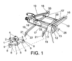
- the luggage carrier of the invention comprises first a support (1) intended to be removably fixed on the bar corresponding to the ball of the type assembled on the rear portion of a vehicle in order to tow a caravan, a trailer or the like.
- This support (1) has a pair of parts (2) between which a passage (3) is defined for the bar of the rear vehicle ball, the fixing being carried out by means of screws (4) fixing the two parts (2) together and pressing the clamp against said bar of the ball.
- One of these parts (2) has a projecting wing (5) perpendicular to the part and in correspondence with its outer side, on which as many elements (6) are collaterally assembled, the fixing being carried out by means of a transverse screw (7) passing through a wing of these side parts (6) and through said extension or wing (5), the side elements (6) having a recess (8) on their ends and corresponding to the upper corner, in which an opening (9) can be seen the function of which shall be detailed below.
- the assembly of the support (1) just described is assembled either in a permanent manner or in a removable manner on the bar corresponding to the rear ball of a vehicle, such that the structure constituting the luggage carrier is anchored on that support, said structure comprising longitudinal beams formed by two elements (10) and (10') in a telescopic position such that the inner element (10') of each longitudinal beam has on one of its ends a part (11) integral with a plate (12) complementary to another plate (13) provided for that purpose on the outer element (10)of the telescopic longitudinal beams forming the luggage carrier structure, such that in the retracted position the plates (12) and (13) connect together with a power source from the vehicle in order to supply power to the rear lights (14) assembled on a license plate support (15) arranged on the rear portion of said structure, specifically fixed to the end brackets (16) provided on the longitudinal beams and in particular on the outer elements (10) of said telescopic longitudinal beams, all this as a consequence of needing a support (15) with the corresponding vehicle license plate and signalling lights (1
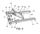
- Said structure has a front crossbeam (17) on which a conventional device (18) for hitching onto the vehicle ball is fixed, whereas a on the other intermediate crossbeam between the longitudinal beams of the structure a framework (19) has been provided with an articulation (20) to said intermediate crossbar such that the arms forming said framework (19) may be adjusted with a larger or smaller angle regarding the structure formed by the longitudinal beams (10-10'), these arms or framework (19) having coupling elements (21) on their free ends intended for being locked in the openings (9) of the previously described general support (1), the anchoring being secured and reinforced by means of brackets (22)in order to prevent bending of the pivots or coupling elements (21).
- the telescopic system of the longitudinal beams (10) and (10') of the luggage carrier structure allows shifting the luggage, such as a dog crate or basket (23), allowing opening the rear door (24) of a vehicle (25) as shown in Figure 4, corresponding to an off-road vehicle with a back door, since Figure 3 shows a vehicle (25') without a back door, the backward shifting or extension of the longitudinal beams (10-10') thereby not being necessary since the boot door of this vehicle (25') can be opened with the luggage carrier in its retracted position.
- the plates (12) and (13) form a direct connection or electrical connection to supply power to the lights and license plate light located on the license plate support (15) arranged on the rear.
- the inclination of the framework formed by the arms (19) may be adjusted, that is, it may provide the luggage carrier or structure formed by the longitudinal beams (10) and (10') with more or less height, according to the position said framework (19) occupies, the arms thereof being articulated at (20) on the crossbar arranged between the longitudinal beams of the luggage carrier structure.
- rods or pivots (27) for being housed in openings provided for that purpose in the lower portion of the crate or luggage (23) in order to achieve immobilisation thereof.
- the crate or luggage (23) provides that the windows seen thereon, due to their being a case for transporting dogs, are removed and placed through side and end guides, being fixed on the upper portion by means of locks.
Abstract
Description
- The present invention refers to a rear luggage carrier for vehicles, these being cars, vans, off-road vehicles, etc., the luggage carrier being provided so that it uses in its coupling the classic towing hitch assembled in one way or another on automotive vehicles, the luggage carrier being cantilever suspended backwards, being able to support objects such as bicycles, crates, etc.
- The luggage carrier is materialised in a support capable of directly receiving any object considered as luggage, or rather receive an integrally attached container which houses said luggage, a container which if suitably fitted can allow carrying animals, such as dogs, in the case of hunters.
- The applicant is proprietor of Spanish Utility Models with application numbers 9501540 and 9801082, in which as many automobile luggage carriers are disclosed, capable of being used in any of the aforementioned cases, based in both cases on a support fixed on the bar finishing in a towing ball for trailers, caravans and the like assembled on some vehicles, such that a structure based on two longitudinal beams with a crossbeam on one of the ends is removably fixed to that support duly fixed to the rear vehicle ball, arranged on which crossbeam there is a conventional hitch element coupling to the rear vehicle ball, whereas between the longitudinal beams a framework is assembled formed by two arms carrying the coupling element coupling onto the support duly secured on the bar of the rear vehicle ball, this framework forming an angle with the longitudinal beam structure, which angle is variable.
- Despite the properties and features of the luggage carriers corresponding to these two utility models of the same applicant, a series of innovations and improvements are provided which are intended to be protected in the present utility model.
- The luggage carrier set forth has as a first novel feature a greatly robust support which is easy to assemble and remove from the rear vehicle bumper, support formed by the combination of two sets of parts, one defined by two parts between which a clamp is formed and which extends in a transverse wing, perpendicularly to which two side profiles are assembled which are secured to this perpendicular extension by means of a through screw, with the particularity that these side elements have a recess in one of their corners, specifically the upper one, and in this recess they have an opening for attaching pivots arranged for that purpose on the structure forming the luggage carrier, a structure having the particularity of being telescopic so that it can be conveniently retracted and extended, and having means forming a direct connection, in the retracted position, between a rear-assembled support carrying the rear lights and additional license plate apart from the vehicle license plate, and the vehicle itself without having to bring out supplementary conduits in order to provide the power supply to the rear lights and the license plate lights when the luggage carrier is assembled on the rear portion of the vehicle in question, in which case it shall logically have the license plate and lights in its rear portion, since the conventional ones of the vehicle are partly hidden by the support and the luggage that it may carry.
- Another novel feature is that the framework having the pivots attaching in the openings of the side elements or parts of the support anchored to the rear vehicle ball swivels and may be placed in different positions, and the coupling elements are complemented with stiffening brackets which on the one hand provide greater strength to the coupling element and further define an immobilising means for said coupling element.
- Another novel feature is that the longitudinal beams have transverse bolts for locking the telescopic parts thereof with one another.
- These and other features, as well as the advantages derived from them, shall be discussed throughout the present description.
- In order to complement the description being made and for the object of aiding towards a better understanding of the features of the invention according to a preferred practical embodiment thereof, a set of drawings is attached as an integral part of said description, in which the following is shown in an illustrative and non-limiting manner:
- Figure 1 shows a perspective view of the luggage carrier of the invention, showing the anchoring support for coupling to the rear vehicle ball and the structure forming the luggage carrier itself.
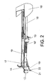
- Figure 2 shows a perspective view of the luggage carrier in its extended position.
- Figure 3 shows a practical application of the luggage carrier arranged on the rear portion of an automotive vehicle and a crate on said luggage carrier.
- Figure 4 shows another practical application on another type of vehicle, showing the luggage carrier completely extended in this case in order to open the rear vehicle door.
- Figure 5 shows a lower perspective view of the luggage carrier, showing the swivelling movement of the anchoring framework, the bolts of the telescopic longitudinal beam locking sides and anchoring pins for anchoring , for example, a crate arranged on the lugg age carrier.
-
- In view of the figures described it can be seen how the luggage carrier of the invention comprises first a support (1) intended to be removably fixed on the bar corresponding to the ball of the type assembled on the rear portion of a vehicle in order to tow a caravan, a trailer or the like. This support (1) has a pair of parts (2) between which a passage (3) is defined for the bar of the rear vehicle ball, the fixing being carried out by means of screws (4) fixing the two parts (2) together and pressing the clamp against said bar of the ball. One of these parts (2) has a projecting wing (5) perpendicular to the part and in correspondence with its outer side, on which as many elements (6) are collaterally assembled, the fixing being carried out by means of a transverse screw (7) passing through a wing of these side parts (6) and through said extension or wing (5), the side elements (6) having a recess (8) on their ends and corresponding to the upper corner, in which an opening (9) can be seen the function of which shall be detailed below. The assembly of the support (1) just described is assembled either in a permanent manner or in a removable manner on the bar corresponding to the rear ball of a vehicle, such that the structure constituting the luggage carrier is anchored on that support, said structure comprising longitudinal beams formed by two elements (10) and (10') in a telescopic position such that the inner element (10') of each longitudinal beam has on one of its ends a part (11) integral with a plate (12) complementary to another plate (13) provided for that purpose on the outer element (10)of the telescopic longitudinal beams forming the luggage carrier structure, such that in the retracted position the plates (12) and (13) connect together with a power source from the vehicle in order to supply power to the rear lights (14) assembled on a license plate support (15) arranged on the rear portion of said structure, specifically fixed to the end brackets (16) provided on the longitudinal beams and in particular on the outer elements (10) of said telescopic longitudinal beams, all this as a consequence of needing a support (15) with the corresponding vehicle license plate and signalling lights (14) when the luggage carrier is assembled on the rear portion of a vehicle, these being fed when the elements from plates (12) and (13) are interconnected with one another, all this without having to arrange connections for the power supply to that rear license plate and the rear lights.
- Said structure has a front crossbeam (17) on which a conventional device (18) for hitching onto the vehicle ball is fixed, whereas a on the other intermediate crossbeam between the longitudinal beams of the structure a framework (19) has been provided with an articulation (20) to said intermediate crossbar such that the arms forming said framework (19) may be adjusted with a larger or smaller angle regarding the structure formed by the longitudinal beams (10-10'), these arms or framework (19) having coupling elements (21) on their free ends intended for being locked in the openings (9) of the previously described general support (1), the anchoring being secured and reinforced by means of brackets (22)in order to prevent bending of the pivots or coupling elements (21).
- The telescopic system of the longitudinal beams (10) and (10') of the luggage carrier structure allows shifting the luggage, such as a dog crate or basket (23), allowing opening the rear door (24) of a vehicle (25) as shown in Figure 4, corresponding to an off-road vehicle with a back door, since Figure 3 shows a vehicle (25') without a back door, the backward shifting or extension of the longitudinal beams (10-10') thereby not being necessary since the boot door of this vehicle (25') can be opened with the luggage carrier in its retracted position.
- As has already been mentioned, with the luggage carrier in its retracted position as represented in Figure 3 or even in Figure 5, the plates (12) and (13) form a direct connection or electrical connection to supply power to the lights and license plate light located on the license plate support (15) arranged on the rear.
- The inclination of the framework formed by the arms (19) may be adjusted, that is, it may provide the luggage carrier or structure formed by the longitudinal beams (10) and (10') with more or less height, according to the position said framework (19) occupies, the arms thereof being articulated at (20) on the crossbar arranged between the longitudinal beams of the luggage carrier structure.
- In the retracted position, as shown in Figure 4, the longitudinal beams (10) and (10') are locked with one another by means of manually actuated bolts (26) assembled sideways, said bolts being housed in opposite openings in that retracted position of the longitudinal beams (10) and (10').
- Likewise, provided on the crossbeam (17) of the structure formed by the longitudinal beams (10) and (10') there are rods or pivots (27) for being housed in openings provided for that purpose in the lower portion of the crate or luggage (23) in order to achieve immobilisation thereof.
- The crate or luggage (23) provides that the windows seen thereon, due to their being a case for transporting dogs, are removed and placed through side and end guides, being fixed on the upper portion by means of locks.
Claims (3)
- A rear luggage carrier for vehicles which, being of the type using a support intended to be irremovably fixed to the classic rear vehicle towing hitch or bar carrying the ball assembled on vehicles on their rear portion, and having a structure formed by two longitudinal beams with a crossbeam on one of the ends provided with a conventional fixing device for fixing it to said rear vehicle ball , and on the structure of which a framework is assembled with coupling elements for coupling in orifices arranged for that purpose on the support fixed to the rear vehicle hitch, characterised in that said support, formed by two parts fixed to one another in the manner of a clamp, has a perpendicular plate to which as many side parts are assembled by means of a transverse common screw, the parts of which are provided on the upper portion of their corners with a recess in which the anchoring opening for the coupling elements of the framework provided on the structure determined by the longitudinal beams is arranged; having been provided that each longitudinal beam is formed by two elements telescopically assembled together which can be fixed in their retracted or operating positions by means of transverse bolts, whereas the framework, formed by as many arms, is articulated to an intermediate crossbeam of the structure formed by the longitudinal beams.
- A rear luggage carrier for vehicles according to claim 1, characterised in that the longitudinal beams of each one of the sides have as many parts or plates with connection elements for establishing, in the operating or retracted positions of said telescopic longitudinal beams, the power supply from the vehicle to the corresponding rear lights and license plate light placed on a support assembled on the rear portion or free end corresponding to the longitudinal beams forming the luggage carrier structure.
- A rear luggage carrier for vehicles according to claim 1, characterised in that the coupling elements arranged on the free ends of the framework articulated between the longitudinal beams of the luggage carrier structure are complemented by stiffening brackets preventing these coupling elements from bending, stiffening the anchoring of the luggage carrier assembly to the support which can be fixed to the rear portion of the vehicle.
Applications Claiming Priority (2)
| Application Number | Priority Date | Filing Date | Title |
|---|---|---|---|
| ES200401532U ES1057890Y (en) | 2004-06-23 | 2004-06-23 | REAR CARRIER FOR VEHICLES. |
| ES200401532U | 2004-06-23 |
Publications (2)
| Publication Number | Publication Date |
|---|---|
| EP1609678A1 true EP1609678A1 (en) | 2005-12-28 |
| EP1609678B1 EP1609678B1 (en) | 2007-04-18 |
Family
ID=33186268
Family Applications (1)
| Application Number | Title | Priority Date | Filing Date |
|---|---|---|---|
| EP05380136A Not-in-force EP1609678B1 (en) | 2004-06-23 | 2005-06-23 | Rear luggage carrier for vehicles |
Country Status (5)
| Country | Link |
|---|---|
| EP (1) | EP1609678B1 (en) |
| AT (1) | ATE359935T1 (en) |
| DE (1) | DE602005000912T2 (en) |
| ES (1) | ES1057890Y (en) |
| PT (1) | PT1609678E (en) |
Cited By (4)
| Publication number | Priority date | Publication date | Assignee | Title |
|---|---|---|---|---|
| EP1868847B2 (en) † | 2005-04-15 | 2013-04-03 | BOS GmbH & Co. KG | Device for a load carrier attached to a vehicle |
| US8827128B2 (en) | 2011-02-15 | 2014-09-09 | GM Global Technology Operations LLC | Cargo carrier system for a motor vehicle with integrated energy supply device |
| EP2364880B1 (en) | 2007-03-23 | 2018-08-15 | WESTFALIA - Automotive GmbH | Load carrier for a motor vehicle |
| CN113022454A (en) * | 2021-04-08 | 2021-06-25 | 捷柯汽车零部件(宁波)有限公司 | Automobile luggage rack |
Citations (8)
| Publication number | Priority date | Publication date | Assignee | Title |
|---|---|---|---|---|
| US3650443A (en) * | 1970-11-23 | 1972-03-21 | Harlan G Haskett | Carrier connectable to automobile bumper and trailer hitch |
| US4906015A (en) * | 1988-11-08 | 1990-03-06 | Lacroix Colan L | Vehicle mounted utility rack |
| DE4242266A1 (en) * | 1992-12-15 | 1994-06-16 | Himmermann Fritz Gmbh Co Kg | Load frame for fitting to tow coupling of vehicle - has coupling head for tow ball and with two lower support arms to grip transverse bar under tow coupling |
| ES1031207U (en) | 1995-05-30 | 1995-12-01 | Mesas Luis Saez | Racks for cars. (Machine-translation by Google Translate, not legally binding) |
| US5586702A (en) * | 1995-04-12 | 1996-12-24 | Sadler; William R. | Vehicle cargo carrier |
| ES1040079U (en) | 1998-04-24 | 1999-03-01 | Saez Mesas Luis | Rear racks for cars. (Machine-translation by Google Translate, not legally binding) |
| GB2353507A (en) * | 1999-08-21 | 2001-02-28 | David Frederick White | Tow hitch mounting arrangement for vehicle load carrier |
| GB2393430A (en) * | 2002-09-02 | 2004-03-31 | Eurotech Leisure Ltd | Cargo carrying apparatus |
-
2004
- 2004-06-23 ES ES200401532U patent/ES1057890Y/en not_active Expired - Fee Related
-
2005
- 2005-06-23 AT AT05380136T patent/ATE359935T1/en not_active IP Right Cessation
- 2005-06-23 PT PT05380136T patent/PT1609678E/en unknown
- 2005-06-23 DE DE602005000912T patent/DE602005000912T2/en active Active
- 2005-06-23 EP EP05380136A patent/EP1609678B1/en not_active Not-in-force
Patent Citations (8)
| Publication number | Priority date | Publication date | Assignee | Title |
|---|---|---|---|---|
| US3650443A (en) * | 1970-11-23 | 1972-03-21 | Harlan G Haskett | Carrier connectable to automobile bumper and trailer hitch |
| US4906015A (en) * | 1988-11-08 | 1990-03-06 | Lacroix Colan L | Vehicle mounted utility rack |
| DE4242266A1 (en) * | 1992-12-15 | 1994-06-16 | Himmermann Fritz Gmbh Co Kg | Load frame for fitting to tow coupling of vehicle - has coupling head for tow ball and with two lower support arms to grip transverse bar under tow coupling |
| US5586702A (en) * | 1995-04-12 | 1996-12-24 | Sadler; William R. | Vehicle cargo carrier |
| ES1031207U (en) | 1995-05-30 | 1995-12-01 | Mesas Luis Saez | Racks for cars. (Machine-translation by Google Translate, not legally binding) |
| ES1040079U (en) | 1998-04-24 | 1999-03-01 | Saez Mesas Luis | Rear racks for cars. (Machine-translation by Google Translate, not legally binding) |
| GB2353507A (en) * | 1999-08-21 | 2001-02-28 | David Frederick White | Tow hitch mounting arrangement for vehicle load carrier |
| GB2393430A (en) * | 2002-09-02 | 2004-03-31 | Eurotech Leisure Ltd | Cargo carrying apparatus |
Cited By (5)
| Publication number | Priority date | Publication date | Assignee | Title |
|---|---|---|---|---|
| EP1868847B2 (en) † | 2005-04-15 | 2013-04-03 | BOS GmbH & Co. KG | Device for a load carrier attached to a vehicle |
| EP2364880B1 (en) | 2007-03-23 | 2018-08-15 | WESTFALIA - Automotive GmbH | Load carrier for a motor vehicle |
| US8827128B2 (en) | 2011-02-15 | 2014-09-09 | GM Global Technology Operations LLC | Cargo carrier system for a motor vehicle with integrated energy supply device |
| CN113022454A (en) * | 2021-04-08 | 2021-06-25 | 捷柯汽车零部件(宁波)有限公司 | Automobile luggage rack |
| CN113022454B (en) * | 2021-04-08 | 2022-08-12 | 捷柯汽车零部件(宁波)有限公司 | Automobile luggage rack |
Also Published As
| Publication number | Publication date |
|---|---|
| ES1057890Y (en) | 2005-01-16 |
| DE602005000912T2 (en) | 2008-01-17 |
| DE602005000912D1 (en) | 2007-05-31 |
| EP1609678B1 (en) | 2007-04-18 |
| PT1609678E (en) | 2007-06-29 |
| ATE359935T1 (en) | 2007-05-15 |
| ES1057890U (en) | 2004-10-01 |
Similar Documents
| Publication | Publication Date | Title |
|---|---|---|
| US6378893B1 (en) | Extendable trailer | |
| US5038983A (en) | Vehicle cargo carrier attachment | |
| US3796333A (en) | Detachable carrier for vehicles | |
| US5836493A (en) | Vehicular mount for cargo carrier | |
| US6129371A (en) | Dual level hitch | |
| US7845711B2 (en) | Quick-attach/detach cab for vehicle | |
| US6969084B2 (en) | Automotive bumper with integral hitch cover | |
| US6742799B1 (en) | Hitch adapter | |
| US7992751B1 (en) | Cargo carrier | |
| US20040032112A1 (en) | Universal hitch and receiver assembly | |
| US8328263B1 (en) | Bed extender | |
| US8556287B1 (en) | Adaptor for attaching fifth wheel hitch | |
| US5571270A (en) | Hitch assembly with retractable trailer coupling | |
| US5836494A (en) | Vehicular cargo carrier assembly | |
| US7121574B2 (en) | Pin box assembly having interchangeable hitch couplers | |
| GB2195304A (en) | Load carrier | |
| EP1609678B1 (en) | Rear luggage carrier for vehicles | |
| US4480578A (en) | Bracket for attaching demountable parts to vehicles and the like | |
| KR20020097212A (en) | Trailer hitch assembly with accessory ports | |
| EP1772358B1 (en) | Trailer which can be coupled behind a passenger car, method for manufacturing or adapting such trailer | |
| US7591478B2 (en) | Vehicle hitch assembly for a vehicle and method of utilizing the same | |
| US20040245795A1 (en) | Cargo bed extension | |
| DE102010012774A1 (en) | Rear suspension system for car to transport bicycles, has mounting adaptor arranged at base frame, and engaging elements for releasable connection with mounting adaptor formed or arranged at individually formed merchandise support | |
| DE19537287C2 (en) | Container transport device for a vehicle | |
| US20060261024A1 (en) | Boat rack for vehicle |
Legal Events
| Date | Code | Title | Description |
|---|---|---|---|
| PUAI | Public reference made under article 153(3) epc to a published international application that has entered the european phase |
Free format text: ORIGINAL CODE: 0009012 |
|
| AK | Designated contracting states |
Kind code of ref document: A1 Designated state(s): AT BE BG CH CY CZ DE DK EE ES FI FR GB GR HU IE IS IT LI LT LU MC NL PL PT RO SE SI SK TR |
|
| AX | Request for extension of the european patent |
Extension state: AL BA HR LV MK YU |
|
| 17P | Request for examination filed |
Effective date: 20060627 |
|
| AKX | Designation fees paid |
Designated state(s): AT BE BG CH CY CZ DE DK EE ES FI FR GB GR HU IE IS IT LI LT LU MC NL PL PT RO SE SI SK TR |
|
| GRAP | Despatch of communication of intention to grant a patent |
Free format text: ORIGINAL CODE: EPIDOSNIGR1 |
|
| GRAS | Grant fee paid |
Free format text: ORIGINAL CODE: EPIDOSNIGR3 |
|
| GRAA | (expected) grant |
Free format text: ORIGINAL CODE: 0009210 |
|
| AK | Designated contracting states |
Kind code of ref document: B1 Designated state(s): AT BE BG CH CY CZ DE DK EE ES FI FR GB GR HU IE IS IT LI LT LU MC NL PL PT RO SE SI SK TR |
|
| PG25 | Lapsed in a contracting state [announced via postgrant information from national office to epo] |
Ref country code: LI Free format text: LAPSE BECAUSE OF FAILURE TO SUBMIT A TRANSLATION OF THE DESCRIPTION OR TO PAY THE FEE WITHIN THE PRESCRIBED TIME-LIMIT Effective date: 20070418 Ref country code: CH Free format text: LAPSE BECAUSE OF FAILURE TO SUBMIT A TRANSLATION OF THE DESCRIPTION OR TO PAY THE FEE WITHIN THE PRESCRIBED TIME-LIMIT Effective date: 20070418 Ref country code: FI Free format text: LAPSE BECAUSE OF FAILURE TO SUBMIT A TRANSLATION OF THE DESCRIPTION OR TO PAY THE FEE WITHIN THE PRESCRIBED TIME-LIMIT Effective date: 20070418 Ref country code: SI Free format text: LAPSE BECAUSE OF FAILURE TO SUBMIT A TRANSLATION OF THE DESCRIPTION OR TO PAY THE FEE WITHIN THE PRESCRIBED TIME-LIMIT Effective date: 20070418 |
|
| REG | Reference to a national code |
Ref country code: CH Ref legal event code: EP |
|
| REG | Reference to a national code |
Ref country code: IE Ref legal event code: FG4D |
|
| REF | Corresponds to: |
Ref document number: 602005000912 Country of ref document: DE Date of ref document: 20070531 Kind code of ref document: P |
|
| REG | Reference to a national code |
Ref country code: PT Ref legal event code: SC4A Free format text: AVAILABILITY OF NATIONAL TRANSLATION Effective date: 20070619 |
|
| PG25 | Lapsed in a contracting state [announced via postgrant information from national office to epo] |
Ref country code: SE Free format text: LAPSE BECAUSE OF FAILURE TO SUBMIT A TRANSLATION OF THE DESCRIPTION OR TO PAY THE FEE WITHIN THE PRESCRIBED TIME-LIMIT Effective date: 20070718 |
|
| PG25 | Lapsed in a contracting state [announced via postgrant information from national office to epo] |
Ref country code: ES Free format text: LAPSE BECAUSE OF FAILURE TO SUBMIT A TRANSLATION OF THE DESCRIPTION OR TO PAY THE FEE WITHIN THE PRESCRIBED TIME-LIMIT Effective date: 20070729 |
|
| PG25 | Lapsed in a contracting state [announced via postgrant information from national office to epo] |
Ref country code: IS Free format text: LAPSE BECAUSE OF FAILURE TO SUBMIT A TRANSLATION OF THE DESCRIPTION OR TO PAY THE FEE WITHIN THE PRESCRIBED TIME-LIMIT Effective date: 20070818 |
|
| ET | Fr: translation filed | ||
| REG | Reference to a national code |
Ref country code: CH Ref legal event code: PL |
|
| NLV1 | Nl: lapsed or annulled due to failure to fulfill the requirements of art. 29p and 29m of the patents act | ||
| PG25 | Lapsed in a contracting state [announced via postgrant information from national office to epo] |
Ref country code: PL Free format text: LAPSE BECAUSE OF FAILURE TO SUBMIT A TRANSLATION OF THE DESCRIPTION OR TO PAY THE FEE WITHIN THE PRESCRIBED TIME-LIMIT Effective date: 20070418 Ref country code: AT Free format text: LAPSE BECAUSE OF FAILURE TO SUBMIT A TRANSLATION OF THE DESCRIPTION OR TO PAY THE FEE WITHIN THE PRESCRIBED TIME-LIMIT Effective date: 20070418 |
|
| PG25 | Lapsed in a contracting state [announced via postgrant information from national office to epo] |
Ref country code: NL Free format text: LAPSE BECAUSE OF FAILURE TO SUBMIT A TRANSLATION OF THE DESCRIPTION OR TO PAY THE FEE WITHIN THE PRESCRIBED TIME-LIMIT Effective date: 20070418 Ref country code: MC Free format text: LAPSE BECAUSE OF NON-PAYMENT OF DUE FEES Effective date: 20070630 Ref country code: DK Free format text: LAPSE BECAUSE OF FAILURE TO SUBMIT A TRANSLATION OF THE DESCRIPTION OR TO PAY THE FEE WITHIN THE PRESCRIBED TIME-LIMIT Effective date: 20070418 Ref country code: BG Free format text: LAPSE BECAUSE OF FAILURE TO SUBMIT A TRANSLATION OF THE DESCRIPTION OR TO PAY THE FEE WITHIN THE PRESCRIBED TIME-LIMIT Effective date: 20070718 Ref country code: CZ Free format text: LAPSE BECAUSE OF FAILURE TO SUBMIT A TRANSLATION OF THE DESCRIPTION OR TO PAY THE FEE WITHIN THE PRESCRIBED TIME-LIMIT Effective date: 20070418 |
|
| PLBE | No opposition filed within time limit |
Free format text: ORIGINAL CODE: 0009261 |
|
| STAA | Information on the status of an ep patent application or granted ep patent |
Free format text: STATUS: NO OPPOSITION FILED WITHIN TIME LIMIT |
|
| PG25 | Lapsed in a contracting state [announced via postgrant information from national office to epo] |
Ref country code: LT Free format text: LAPSE BECAUSE OF FAILURE TO SUBMIT A TRANSLATION OF THE DESCRIPTION OR TO PAY THE FEE WITHIN THE PRESCRIBED TIME-LIMIT Effective date: 20070418 Ref country code: SK Free format text: LAPSE BECAUSE OF FAILURE TO SUBMIT A TRANSLATION OF THE DESCRIPTION OR TO PAY THE FEE WITHIN THE PRESCRIBED TIME-LIMIT Effective date: 20070418 |
|
| 26N | No opposition filed |
Effective date: 20080121 |
|
| PG25 | Lapsed in a contracting state [announced via postgrant information from national office to epo] |
Ref country code: GR Free format text: LAPSE BECAUSE OF FAILURE TO SUBMIT A TRANSLATION OF THE DESCRIPTION OR TO PAY THE FEE WITHIN THE PRESCRIBED TIME-LIMIT Effective date: 20070719 |
|
| PG25 | Lapsed in a contracting state [announced via postgrant information from national office to epo] |
Ref country code: RO Free format text: LAPSE BECAUSE OF FAILURE TO SUBMIT A TRANSLATION OF THE DESCRIPTION OR TO PAY THE FEE WITHIN THE PRESCRIBED TIME-LIMIT Effective date: 20070418 Ref country code: IE Free format text: LAPSE BECAUSE OF NON-PAYMENT OF DUE FEES Effective date: 20070625 |
|
| PG25 | Lapsed in a contracting state [announced via postgrant information from national office to epo] |
Ref country code: EE Free format text: LAPSE BECAUSE OF FAILURE TO SUBMIT A TRANSLATION OF THE DESCRIPTION OR TO PAY THE FEE WITHIN THE PRESCRIBED TIME-LIMIT Effective date: 20070418 |
|
| PG25 | Lapsed in a contracting state [announced via postgrant information from national office to epo] |
Ref country code: CY Free format text: LAPSE BECAUSE OF FAILURE TO SUBMIT A TRANSLATION OF THE DESCRIPTION OR TO PAY THE FEE WITHIN THE PRESCRIBED TIME-LIMIT Effective date: 20070418 |
|
| PG25 | Lapsed in a contracting state [announced via postgrant information from national office to epo] |
Ref country code: LU Free format text: LAPSE BECAUSE OF NON-PAYMENT OF DUE FEES Effective date: 20070623 |
|
| PG25 | Lapsed in a contracting state [announced via postgrant information from national office to epo] |
Ref country code: TR Free format text: LAPSE BECAUSE OF FAILURE TO SUBMIT A TRANSLATION OF THE DESCRIPTION OR TO PAY THE FEE WITHIN THE PRESCRIBED TIME-LIMIT Effective date: 20070418 Ref country code: HU Free format text: LAPSE BECAUSE OF FAILURE TO SUBMIT A TRANSLATION OF THE DESCRIPTION OR TO PAY THE FEE WITHIN THE PRESCRIBED TIME-LIMIT Effective date: 20071019 |
|
| PGFP | Annual fee paid to national office [announced via postgrant information from national office to epo] |
Ref country code: PT Payment date: 20110609 Year of fee payment: 7 |
|
| PGFP | Annual fee paid to national office [announced via postgrant information from national office to epo] |
Ref country code: GB Payment date: 20110610 Year of fee payment: 7 |
|
| PGFP | Annual fee paid to national office [announced via postgrant information from national office to epo] |
Ref country code: DE Payment date: 20110621 Year of fee payment: 7 Ref country code: BE Payment date: 20110627 Year of fee payment: 7 |
|
| BERE | Be: lapsed |
Owner name: SAEZ MESAS, LUIS Effective date: 20120630 |
|
| REG | Reference to a national code |
Ref country code: PT Ref legal event code: MM4A Free format text: LAPSE DUE TO NON-PAYMENT OF FEES Effective date: 20121226 |
|
| GBPC | Gb: european patent ceased through non-payment of renewal fee |
Effective date: 20120623 |
|
| PG25 | Lapsed in a contracting state [announced via postgrant information from national office to epo] |
Ref country code: PT Free format text: LAPSE BECAUSE OF NON-PAYMENT OF DUE FEES Effective date: 20121226 |
|
| REG | Reference to a national code |
Ref country code: DE Ref legal event code: R119 Ref document number: 602005000912 Country of ref document: DE Effective date: 20130101 |
|
| PG25 | Lapsed in a contracting state [announced via postgrant information from national office to epo] |
Ref country code: BE Free format text: LAPSE BECAUSE OF NON-PAYMENT OF DUE FEES Effective date: 20120630 Ref country code: GB Free format text: LAPSE BECAUSE OF NON-PAYMENT OF DUE FEES Effective date: 20120623 Ref country code: DE Free format text: LAPSE BECAUSE OF NON-PAYMENT OF DUE FEES Effective date: 20130101 |
|
| PGFP | Annual fee paid to national office [announced via postgrant information from national office to epo] |
Ref country code: IT Payment date: 20140626 Year of fee payment: 10 |
|
| PGFP | Annual fee paid to national office [announced via postgrant information from national office to epo] |
Ref country code: FR Payment date: 20140611 Year of fee payment: 10 |
|
| PG25 | Lapsed in a contracting state [announced via postgrant information from national office to epo] |
Ref country code: IT Free format text: LAPSE BECAUSE OF NON-PAYMENT OF DUE FEES Effective date: 20150623 |
|
| REG | Reference to a national code |
Ref country code: FR Ref legal event code: ST Effective date: 20160229 |
|
| PG25 | Lapsed in a contracting state [announced via postgrant information from national office to epo] |
Ref country code: FR Free format text: LAPSE BECAUSE OF NON-PAYMENT OF DUE FEES Effective date: 20150630 |