EP1609580A2 - Controller of ejector mechanism in injection molding machine and method of setting terminal position of ejector pins - Google Patents
Controller of ejector mechanism in injection molding machine and method of setting terminal position of ejector pins Download PDFInfo
- Publication number
- EP1609580A2 EP1609580A2 EP05253887A EP05253887A EP1609580A2 EP 1609580 A2 EP1609580 A2 EP 1609580A2 EP 05253887 A EP05253887 A EP 05253887A EP 05253887 A EP05253887 A EP 05253887A EP 1609580 A2 EP1609580 A2 EP 1609580A2
- Authority
- EP
- European Patent Office
- Prior art keywords
- ejector pins
- elastic force
- ejector
- springs
- forward motion
- Prior art date
- Legal status (The legal status is an assumption and is not a legal conclusion. Google has not performed a legal analysis and makes no representation as to the accuracy of the status listed.)
- Withdrawn
Links
- 238000001746 injection moulding Methods 0.000 title claims abstract description 17
- 238000000034 method Methods 0.000 title claims abstract description 15
- 230000033001 locomotion Effects 0.000 claims abstract description 83
- 230000005540 biological transmission Effects 0.000 description 3
- 238000000465 moulding Methods 0.000 description 3
- 238000004364 calculation method Methods 0.000 description 2
- 238000013500 data storage Methods 0.000 description 2
- 238000010586 diagram Methods 0.000 description 2
- 230000007257 malfunction Effects 0.000 description 2
- 230000006835 compression Effects 0.000 description 1
- 238000007906 compression Methods 0.000 description 1
- 230000006870 function Effects 0.000 description 1
- 238000002347 injection Methods 0.000 description 1
- 239000007924 injection Substances 0.000 description 1
- 239000004973 liquid crystal related substance Substances 0.000 description 1
- 239000011347 resin Substances 0.000 description 1
- 229920005989 resin Polymers 0.000 description 1
- 230000000717 retained effect Effects 0.000 description 1
Images


Classifications
-
- B—PERFORMING OPERATIONS; TRANSPORTING
- B29—WORKING OF PLASTICS; WORKING OF SUBSTANCES IN A PLASTIC STATE IN GENERAL
- B29C—SHAPING OR JOINING OF PLASTICS; SHAPING OF MATERIAL IN A PLASTIC STATE, NOT OTHERWISE PROVIDED FOR; AFTER-TREATMENT OF THE SHAPED PRODUCTS, e.g. REPAIRING
- B29C45/00—Injection moulding, i.e. forcing the required volume of moulding material through a nozzle into a closed mould; Apparatus therefor
- B29C45/17—Component parts, details or accessories; Auxiliary operations
- B29C45/76—Measuring, controlling or regulating
- B29C45/7626—Measuring, controlling or regulating the ejection or removal of moulded articles
-
- B—PERFORMING OPERATIONS; TRANSPORTING
- B29—WORKING OF PLASTICS; WORKING OF SUBSTANCES IN A PLASTIC STATE IN GENERAL
- B29C—SHAPING OR JOINING OF PLASTICS; SHAPING OF MATERIAL IN A PLASTIC STATE, NOT OTHERWISE PROVIDED FOR; AFTER-TREATMENT OF THE SHAPED PRODUCTS, e.g. REPAIRING
- B29C45/00—Injection moulding, i.e. forcing the required volume of moulding material through a nozzle into a closed mould; Apparatus therefor
- B29C45/17—Component parts, details or accessories; Auxiliary operations
- B29C45/40—Removing or ejecting moulded articles
- B29C45/4005—Ejector constructions; Ejector operating mechanisms
-
- B—PERFORMING OPERATIONS; TRANSPORTING
- B29—WORKING OF PLASTICS; WORKING OF SUBSTANCES IN A PLASTIC STATE IN GENERAL
- B29C—SHAPING OR JOINING OF PLASTICS; SHAPING OF MATERIAL IN A PLASTIC STATE, NOT OTHERWISE PROVIDED FOR; AFTER-TREATMENT OF THE SHAPED PRODUCTS, e.g. REPAIRING
- B29C45/00—Injection moulding, i.e. forcing the required volume of moulding material through a nozzle into a closed mould; Apparatus therefor
- B29C45/17—Component parts, details or accessories; Auxiliary operations
- B29C45/76—Measuring, controlling or regulating
- B29C45/7626—Measuring, controlling or regulating the ejection or removal of moulded articles
- B29C2045/764—Measuring, controlling or regulating the ejection or removal of moulded articles detecting or preventing overload of an ejector
-
- B—PERFORMING OPERATIONS; TRANSPORTING
- B29—WORKING OF PLASTICS; WORKING OF SUBSTANCES IN A PLASTIC STATE IN GENERAL
- B29C—SHAPING OR JOINING OF PLASTICS; SHAPING OF MATERIAL IN A PLASTIC STATE, NOT OTHERWISE PROVIDED FOR; AFTER-TREATMENT OF THE SHAPED PRODUCTS, e.g. REPAIRING
- B29C2945/00—Indexing scheme relating to injection moulding, i.e. forcing the required volume of moulding material through a nozzle into a closed mould
- B29C2945/76—Measuring, controlling or regulating
- B29C2945/76003—Measured parameter
- B29C2945/76013—Force
-
- B—PERFORMING OPERATIONS; TRANSPORTING
- B29—WORKING OF PLASTICS; WORKING OF SUBSTANCES IN A PLASTIC STATE IN GENERAL
- B29C—SHAPING OR JOINING OF PLASTICS; SHAPING OF MATERIAL IN A PLASTIC STATE, NOT OTHERWISE PROVIDED FOR; AFTER-TREATMENT OF THE SHAPED PRODUCTS, e.g. REPAIRING
- B29C2945/00—Indexing scheme relating to injection moulding, i.e. forcing the required volume of moulding material through a nozzle into a closed mould
- B29C2945/76—Measuring, controlling or regulating
- B29C2945/76003—Measured parameter
- B29C2945/76083—Position
-
- B—PERFORMING OPERATIONS; TRANSPORTING
- B29—WORKING OF PLASTICS; WORKING OF SUBSTANCES IN A PLASTIC STATE IN GENERAL
- B29C—SHAPING OR JOINING OF PLASTICS; SHAPING OF MATERIAL IN A PLASTIC STATE, NOT OTHERWISE PROVIDED FOR; AFTER-TREATMENT OF THE SHAPED PRODUCTS, e.g. REPAIRING
- B29C2945/00—Indexing scheme relating to injection moulding, i.e. forcing the required volume of moulding material through a nozzle into a closed mould
- B29C2945/76—Measuring, controlling or regulating
- B29C2945/76003—Measured parameter
- B29C2945/7611—Velocity
-
- B—PERFORMING OPERATIONS; TRANSPORTING
- B29—WORKING OF PLASTICS; WORKING OF SUBSTANCES IN A PLASTIC STATE IN GENERAL
- B29C—SHAPING OR JOINING OF PLASTICS; SHAPING OF MATERIAL IN A PLASTIC STATE, NOT OTHERWISE PROVIDED FOR; AFTER-TREATMENT OF THE SHAPED PRODUCTS, e.g. REPAIRING
- B29C2945/00—Indexing scheme relating to injection moulding, i.e. forcing the required volume of moulding material through a nozzle into a closed mould
- B29C2945/76—Measuring, controlling or regulating
- B29C2945/76177—Location of measurement
- B29C2945/7624—Ejection unit
- B29C2945/76244—Ejection unit ejectors
-
- B—PERFORMING OPERATIONS; TRANSPORTING
- B29—WORKING OF PLASTICS; WORKING OF SUBSTANCES IN A PLASTIC STATE IN GENERAL
- B29C—SHAPING OR JOINING OF PLASTICS; SHAPING OF MATERIAL IN A PLASTIC STATE, NOT OTHERWISE PROVIDED FOR; AFTER-TREATMENT OF THE SHAPED PRODUCTS, e.g. REPAIRING
- B29C2945/00—Indexing scheme relating to injection moulding, i.e. forcing the required volume of moulding material through a nozzle into a closed mould
- B29C2945/76—Measuring, controlling or regulating
- B29C2945/76494—Controlled parameter
- B29C2945/76525—Electric current or voltage
-
- B—PERFORMING OPERATIONS; TRANSPORTING
- B29—WORKING OF PLASTICS; WORKING OF SUBSTANCES IN A PLASTIC STATE IN GENERAL
- B29C—SHAPING OR JOINING OF PLASTICS; SHAPING OF MATERIAL IN A PLASTIC STATE, NOT OTHERWISE PROVIDED FOR; AFTER-TREATMENT OF THE SHAPED PRODUCTS, e.g. REPAIRING
- B29C2945/00—Indexing scheme relating to injection moulding, i.e. forcing the required volume of moulding material through a nozzle into a closed mould
- B29C2945/76—Measuring, controlling or regulating
- B29C2945/76494—Controlled parameter
- B29C2945/76568—Position
- B29C2945/76575—Position end position
-
- B—PERFORMING OPERATIONS; TRANSPORTING
- B29—WORKING OF PLASTICS; WORKING OF SUBSTANCES IN A PLASTIC STATE IN GENERAL
- B29C—SHAPING OR JOINING OF PLASTICS; SHAPING OF MATERIAL IN A PLASTIC STATE, NOT OTHERWISE PROVIDED FOR; AFTER-TREATMENT OF THE SHAPED PRODUCTS, e.g. REPAIRING
- B29C2945/00—Indexing scheme relating to injection moulding, i.e. forcing the required volume of moulding material through a nozzle into a closed mould
- B29C2945/76—Measuring, controlling or regulating
- B29C2945/76655—Location of control
- B29C2945/76719—Ejection unit
- B29C2945/76722—Ejection unit ejectors
-
- B—PERFORMING OPERATIONS; TRANSPORTING
- B29—WORKING OF PLASTICS; WORKING OF SUBSTANCES IN A PLASTIC STATE IN GENERAL
- B29C—SHAPING OR JOINING OF PLASTICS; SHAPING OF MATERIAL IN A PLASTIC STATE, NOT OTHERWISE PROVIDED FOR; AFTER-TREATMENT OF THE SHAPED PRODUCTS, e.g. REPAIRING
- B29C2945/00—Indexing scheme relating to injection moulding, i.e. forcing the required volume of moulding material through a nozzle into a closed mould
- B29C2945/76—Measuring, controlling or regulating
- B29C2945/76929—Controlling method
- B29C2945/76933—The operating conditions are corrected immediately, during the same phase or cycle
-
- B—PERFORMING OPERATIONS; TRANSPORTING
- B29—WORKING OF PLASTICS; WORKING OF SUBSTANCES IN A PLASTIC STATE IN GENERAL
- B29C—SHAPING OR JOINING OF PLASTICS; SHAPING OF MATERIAL IN A PLASTIC STATE, NOT OTHERWISE PROVIDED FOR; AFTER-TREATMENT OF THE SHAPED PRODUCTS, e.g. REPAIRING
- B29C2945/00—Indexing scheme relating to injection moulding, i.e. forcing the required volume of moulding material through a nozzle into a closed mould
- B29C2945/76—Measuring, controlling or regulating
- B29C2945/76929—Controlling method
- B29C2945/76939—Using stored or historical data sets
- B29C2945/76943—Using stored or historical data sets compare with thresholds
Definitions
- the present invention relates to a controller of an ejector mechanism for ejecting a molded product from a mold in an injection molding machine, and also to a method of setting a terminal position of a forward motion of ejector pins of the ejector mechanism.
- an injection molding machine After resin is injected into a mold and concreted, the mold is opened and a molded product in the mold is ejected by an ejector mechanism.
- the ejector mechanism ejects a molded product by moving ejector pins forward to project into a cavity of the mold against an elastic force of return springs for returning the ejector pins to a retracted position.
- a pneumatic cylinder, a linear motor or a servomotor may be employed as a driving source for moving the ejector pins forward.
- a brake device is used for generating a retaining force to retain the ejector pins at a terminal position of the forward motion against the elastic force of the springs (see JP10-296818A, for example).
- the retaining force has to be greater than the elastic force of the springs at the terminal position of the forward motion of the ejector pins. If the elastic force of the springs is greater than the retaining force of the brake device in a state where the ejector pins are retained at the terminal position, friction members for generating braking force, such as a brake shoe and a brake band of the brake device are excessively worn to make a cause of malfunction of the brake device.
- the present invention provides a method of setting a terminal position of a forward motion of ejector pins of an ejector mechanism of an injection molding machine and a controller for controlling the ejector mechanism which enable setting of the terminal position of the forward motion of the ejector pins such that an elastic force of springs for returning the ejector pins to a retracted position does not exceed a retaining force of the brake means for retaining the ejector pins at the terminal position.
- the method of the present invention is provided for setting a terminal position of a forward motion of ejector pins of an ejector mechanism having means for moving the ejector pins forward to project into a mold, springs for generating an elastic force to return the ejector pins to a retracted position, and brake means for generating a retaining force to retain the ejector pins at the terminal position.
- the method comprises: moving the ejector pins forward from the retracted position in a state where no molded product is present in the mold; detecting the elastic force of the springs during the forward motion of the ejector pins; determining a criterial position of the ejector pins where the detected elastic force of the springs is equivalent to the retaining force of the brake means; and setting the terminal position of the forward motion of the ejector pins closer to the retracted position than the determined critical position.
- the controller comprises: position detecting means for detecting a position of the ejector pins; elastic force detecting means for detecting an elastic force of the springs during a forward motion of the ejector pins from the retracted position; determining means for determining a criterial position of the ejector pins where the detected elastic force of the springs is equivalent to the retaining force of the brake means; and display means for displaying the detected criterial position of the ejector pins for setting the terminal position of the forward motion of the ejector pins. Referring to the detected criterial position, an operator can set the terminal position of the forward motion of the ejector pins closer to the retracted position than the determined critical position.
- the controller comprises: position detecting means for detecting a position of the ejector pins; elastic force detecting means for detecting an elastic force of the springs during a forward motion of the ejector pins from a retracted position; determining means for determining a criterial position of the ejector pins where the detected elastic force of the springs is equivalent to the retaining force of the brake means; and means for issuing an alarm if a preset terminal position of the forward motion of the ejector pins is remoter from the retracted position than the criterial position of the ejector pins.
- the controller comprises: position detecting means for detecting a position of the ejector pins; elastic force detecting means for detecting an elastic force of the springs during a forward motion of the ejector pins; determining means for determining a position of the ejector pins immediately before the detected elastic force of the springs exceeds the retaining force of the brake means in the forward motion of the ejector pins; and means for altering a preset terminal position of the forward motion of the ejector pins to be the determined position, if the preset terminal position of the forward motion the ejector pins is remoter from the retracted position than the determined position.
- the preset terminal position of the forward motion of the ejector pins is automatically altered to the determined position where the springs generate the elastic force not greater than the retaining force of the brake means.
- the elastic force detecting means may detect the elastic force of the springs based on a electric current of a servomotor for driving the ejector pins to move forward, or by an observer for estimating a load exerted on the servomotor, or by a strain gauge provided in the ejector mechanism.
- the terminal position of the forward motion of the ejector pins is set to an appropriate position where the return springs generate the elastic force not greater than the retaining force of the brake device, so that the brake device is prevented from excessively wearing to reduce a cause of malfunction of the brake device.
- an ejection plate 2 having ejector pins 3 thereon is arranged in a mold 1.
- the ejector pins 3 are moved forward to project into a cavity of the mold 1 to eject a molded product stuck in cavity of the mold 1.
- Springs 4 are inserted into the ejector pins 3 to be arranged between the ejector plate 2 and an inner wall of the mold 1 to generate an elastic force to urge the ejector pins 3 and the ejector plate 2 to retract from the cavity of the mold 1 to a retracted position.
- An ejector rod 5 is connected to the ejector plate 2 to move the ejector pins 3 forward with the ejector plate 2 (in a right direction in FIG. 1 to project the ejector pins 3 into the cavity) against the elastic force of the springs 4.
- a proximal end of the ejector rod 5 is fixed to a mounting plate 6 which has ball-nuts engaged with ball-screws 7.
- the ball-screws 7 are driven by a servomotor 9 having a built-in brake device through a transmission mechanism such as a timing belt.
- a position/velocity detector 10 is provided at the servomotor 9 to detect a rotational position of the motor to obtain a position and a velocity of the ejector pins 3.
- An ejector controller 20 for controlling the ejector mechanism is constituted using a controller for controlling the injection molding machine.
- the controller 20 has a CNC CPU 27 which serves as a microprocessor for numerical control, a PC CPU 26 which serves as a microprocessor for programmable control, and a servo CPU 22 which serves as a microprocessor for servo control, connected with one another by a bus 25 to enable information transmission in between by selecting input/output to/from the processors.
- a CNC CPU 27 which serves as a microprocessor for numerical control
- a PC CPU 26 which serves as a microprocessor for programmable control
- a servo CPU 22 which serves as a microprocessor for servo control
- the PC CPU 26 is connected to a ROM 30 storing a sequence program for controlling sequential motions of the injection molding machine, and a RAM 31 for temporary storage of calculation data, and the CNC CPU 27 is connected to a ROM 32 storing an automatic operation program for generally controlling the injection molding machine and a RAM 13 for temporary storage of calculation data.
- the servo CPU 22 is connected to a ROM 23 storing a control program dedicated for servo control for performing position, velocity and current control, and a RAM 24 for temporary storage of data. Further, the servo CPU 22 is connected to a servo amplifier 21 of the servomotor 9 for driving the ejector mechanism according to a command from the CPU 22 and an output from the position/velocity detector 10 attached to the servomotor 9 is fed back to the servo CPU 22. The rotational position of the servomotor 9, i.e. the position of the ejector pins 3 is updated based on the feedback signal of the position from the position/velocity detector 10 and stored in a present position storage register. Servo amplifiers of servomotors for driving a mold clamping mechanism and an injection mechanism connected to the servo CPU 22 are omitted in FIG. 1.
- a non-volatile memory 28 which is a data storage RAM is connected to the bus 25 and serves as a molding data storage memory for storing molding conditions regarding injection molding operations, various set values, parameters, and macro variables.
- a preset retaining force of the brake device and a preset terminal position of the forward motion of the ejector pins are stored in the non-volatile memory 28.
- a manual data input (MDI) device 29 with a display device is connected to the bus 25.
- the MDI device 29 is capable of performing screen display of graphs and functional menus, and input of various data with numeral keys and various function keys.
- the display device may be constituted by a CRT, a liquid crystal display, etc.
- the above hardware constitution of the controller is not different from that of a conventional electrical injection molding machine in which the PC CPU 26 controls the sequential motions of the injection molding machine, the CNC CPU 29 controls molding operations.
- the CNC CPU 27 distributes motion commands to the servomotor 9 and the servo CPU 22 performs a servo control, so called as digital servo processing, including a position loop control, a velocity loop control and a current loop control based on the distributed motion commands and the feedback signals of position and velocity from the position/velocity detector 10, to drivingly control the servomotor 9 to perform an ejection of a molded product from the mold 1.
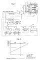
- FIG. 2 shows the elastic force of the springs 4 varying with the position of the ejector pins 3 in comparison with the retaining force of the brake device built in the servomotor 9 to explain a principle of the present invention.
- an axis of abscissa represents a position of the ejector pins 3 in a forward motion thereof
- an axis of ordinate represents an elastic force of the springs 4 varying with the forward motion of the ejector pins 3.
- the ejector pins 3 and the ejector plate 2 are urged to a backward end position in a motion stroke by the springs 4, and compression of the springs 4 increases with the forward motion of the ejector pins 3 (with the ejector rod 5 and the ejector plate 2) so that the elastic force of the springs 4 increases linearly according to a spring constant. If a terminal position of the forward motion of the springs is set in a region where the elastic force Y of the springs 4 is equal to or lower than the retaining force Fb of the brake device provided in the servomotor 9, the retaining force of the brake device is sufficient to retain the ejector pins at the terminal position to cause no problem.
- a position of the ejector pins 3 where the springs 4 generate an elastic force equivalent to the retaining force F of the brake device is determined as a criterial position P of the terminal position of the forward motion of the ejector pins 3, for setting the terminal position closer to the retracted position (the backward end position of the motion stroke) than the criterial position P.
- FIG. 3 shows processing to be performed by the CNC CPU 27 for setting the terminal position of the forward motion of the ejector pins according to a first embodiment of the present invention.
- the CNC CPU 27 outputs a motion command to move the ejector pins 3 forward to a forward end position of a motion stroke of the ejector pins 3.
- the servo CPU 22 performs feedback controls of position and velocity to drive the servomotor 9 through the servo amplifier 21 according to the motion command (Step a1).
- the CNC CPU 27 detects the elastic force of the springs 4 (Step a2).
- the elastic force is detected based on a driving current of the servomotor 9. Since there is no molded product in the mold 1 and thus the ejector pins 3 do not eject any molded product in the forward motion, a load exerted on the servomotor 9 is an elastic force generated by the springs 4 of the ejector mechanism. Since the driving current of the servomotor 9 is proportional to the load exerted on the servomotor 9, the elastic force of the springs 4 can be detected based on the driving current of the servomotor 9.
- the elastic force of the springs 4 may be detected by a strain gauge attached to the ejector rod 5 for detecting a load exerted on the ejector rod 5.
- various types of disturbance estimating observers for estimating disturbance load exerted on the servomotor are known in the art. For instance, there is known an observer for estimating a load on a servomotor based on a current command to the servomotor and an actual velocity of the servomotor. Such an observer (constituted by software) may be incorporated into a program for the servo CPU 22 for controlling the servomotor 9, to detect the load exerted on the servomotor 9, i.e. the elastic force of the springs 4.
- Step a3 a present position of the ejector pins 4, which is stored in a present position storage register based on a feedback signal form the position/velocity detector 10, is set to a register Emax (Step a4). Then, it is determined whether or not the ejector pins reach the forward end of the stroke commanded in Step a2 (Step a4), and if not, the procedure returns to Step a2 to execute the processing of Step a2 and subsequent Steps.
- the position of the ejector pins is updated and stored in the register Exam on condition that the detected elastic force Y is smaller than the retaining force F of the brake device.
- the updating of the register Emax of Step a4 is not performed and the procedure proceeds from Step a3 to Step a5.
- the position of the ejector pins immediately before the elastic force Y exceeds the retaining force F is stored in the register Emax.
- Step a6 the procedure proceeds to Step a6 where the position of the ejector pins stored in the register Emax is displayed as the criterial position of the ejector pins on the display/MDI device 29.
- the terminal position of the forward motion of the ejector pins 3 is set to a position where the elastic force of the springs 4 does not exceed the retaining force of the brake device.
- the present position of the ejector pins 3 is stored in the register Emax so that the position of the ejector pins just one processing period before the elastic force exceeds the retaining force of the brake device (i.e. at this position the elastic force does not exceed the retaining force) is determined.
- the position of the ejector pins first time when the elastic force exceeds the retaining force of the brake device may be stored in the register Emax. For instance, in the processing of FIG.
- Step a3 when it is determined that the elastic force Y exceeds the retaining force F at Step a3, the procedure may proceed to Step a4 where the present position of the ejector pins 3 is stored in the register Exam and a flag is set to "1 ", and after the flag is set the procedure proceeds to Step a5 where it is determined whether or not the ejector pins reaches the forward end of the motion stroke.
- FIG. 4 show processing according to a second embodiment of the present invention. In this second embodiment, it is determined whether or not a preset terminal position of the forward motion of the ejector pins 3 is appropriate.
- Step b 1 to Step b5 the processing of Step b 1 to Step b5 is the same as that of Step a1 to Step a5 of FIG. 3 in which the position of the ejector pins 3 immediately before the elastic force of the springs 4 exceeds the retaining force of the brake device is stored in the register Emax.
- the position of the ejector pins 3 stored in the register Emax is compared with a preset terminal position of the forward motion of the ejector pins 3 in Step b6.
- Step b7 If the preset terminal position of the forward motion of the ejector pins 3 is remoter from the retracted position than the position of the ejector pins 3 stored in the register Emax, an alarm is issued and displayed on a screen of the display/MDI device 29 (Step b7).
- the preset terminal position of the forward motion of the ejector pins 3 is remoter than the position of the ejector pins 3 where the springs 4 generate elastic force exceeding the maximum braking force of the brake device, and therefore an alarm is issued to caution that the preset terminal position is inappropriate to be a cause of excessive wearing of friction members such as brake pad or shoe of the brake device.
- contents of the alarm it is desirable a message prompting a change of setting of the terminal position of the forward motion of the ejector pins or replace the springs to ones having appropriate spring constants.
- the position of the ejector pins when the elastic force of the springs first exceeds the maximum braking force may be stored in the register Emax, as in the first embodiment.
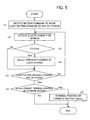
- FIG. 5 is a flowchart of processing according to a third embodiment.
- the terminal position of the forward motion of the ejector pins is automatically re-set to a position immediately before the position where the springs generate an elastic force exceeding the retaining force of the brake device.
- Step c1 to Step c5 is the same as the processing of Step a1 to Step a5 in the first embodiment as shown in FIG. 3 and the processing of Step b1 to Step b5 in the second embodiment as shown in FIG. 4.
- the position of the ejector pins immediately before the springs generate an elastic force exceeding the retaining force of the brake device is compared with the preset terminal position of the forward motion of the ejector pins (Step c6). If the preset terminal position of the forward motion of the ejector pins is the same as or closer to the retracted position than the position stored in the register Emax, the procedure terminates without changing the preset terminal position of the forward motion of the ejector pins. On the other hand, if the preset terminal position of forward motion of the ejector pins is not less than the position stored in the register Emax, the preset terminal position is changed to the position stored in the register Emax (Step c7).
- a molded product can not be ejected from the mold at the altered terminal position of the forward motion of the ejector pins and therefore it is desirable to indicate a message to prompt change to springs of appropriate spring constants on the screen of the display/MDI device 29 when the preset terminal position is altered.
- the elastic force of the springs is detected during the forward motion of the ejector pins from the backward end to the forward end of the motion stroke to determine a position of the ejector pins where the elastic force of the springs exceeds the retaining force of the brake device.
- the elastic force of the springs may be detected during operating the servomotor 9 for driving the ejector pins by a predetermined amount, and if the detected elastic force of the springs does not exceed the retaining force of the brake device, the elastic force of the springs is detected while driving the servomotor 9 by the predetermined amount again to detect a position where the elastic force of the springs exceeds the retaining force of the brake device. Based on the detected position, the terminal position of the forward motion of the ejector pins may be set.
- the servomotor is adopted as a driving source for moving the ejector pins forward.
- the present invention may be applied to an ejector mechanism in which a hydraulic cylinder or a linear motor is used as the driving source.
- the brake device is built in the servomotor in the above embodiments, however, the brake device may be provided at a transmission member provided between the driving source and the ejector rod for transmitting a driving force to drive the ejector mechanism.
Landscapes
- Engineering & Computer Science (AREA)
- Manufacturing & Machinery (AREA)
- Mechanical Engineering (AREA)
- Moulds For Moulding Plastics Or The Like (AREA)
- Injection Moulding Of Plastics Or The Like (AREA)
Abstract
Description
- The present invention relates to a controller of an ejector mechanism for ejecting a molded product from a mold in an injection molding machine, and also to a method of setting a terminal position of a forward motion of ejector pins of the ejector mechanism.
- In an injection molding machine, after resin is injected into a mold and concreted, the mold is opened and a molded product in the mold is ejected by an ejector mechanism. The ejector mechanism ejects a molded product by moving ejector pins forward to project into a cavity of the mold against an elastic force of return springs for returning the ejector pins to a retracted position. A pneumatic cylinder, a linear motor or a servomotor may be employed as a driving source for moving the ejector pins forward. A brake device is used for generating a retaining force to retain the ejector pins at a terminal position of the forward motion against the elastic force of the springs (see JP10-296818A, for example).
- Since the brake device retains the ejector pins at the terminal position against the elastic force of the springs by the retaining force, the retaining force has to be greater than the elastic force of the springs at the terminal position of the forward motion of the ejector pins. If the elastic force of the springs is greater than the retaining force of the brake device in a state where the ejector pins are retained at the terminal position, friction members for generating braking force, such as a brake shoe and a brake band of the brake device are excessively worn to make a cause of malfunction of the brake device.
- The present invention provides a method of setting a terminal position of a forward motion of ejector pins of an ejector mechanism of an injection molding machine and a controller for controlling the ejector mechanism which enable setting of the terminal position of the forward motion of the ejector pins such that an elastic force of springs for returning the ejector pins to a retracted position does not exceed a retaining force of the brake means for retaining the ejector pins at the terminal position.
- The method of the present invention is provided for setting a terminal position of a forward motion of ejector pins of an ejector mechanism having means for moving the ejector pins forward to project into a mold, springs for generating an elastic force to return the ejector pins to a retracted position, and brake means for generating a retaining force to retain the ejector pins at the terminal position. The method comprises: moving the ejector pins forward from the retracted position in a state where no molded product is present in the mold; detecting the elastic force of the springs during the forward motion of the ejector pins; determining a criterial position of the ejector pins where the detected elastic force of the springs is equivalent to the retaining force of the brake means; and setting the terminal position of the forward motion of the ejector pins closer to the retracted position than the determined critical position.
- A controller of the present invention controls an ejector mechanism of an injection molding machine having means for moving ejector pins forward to project into a mold, springs for generating an elastic force to return the ejector pins to a retracted position, and brake means for generating a retaining force to retain the ejector pins at a terminal position of the forward motion. According to an aspect of the invention, the controller comprises: position detecting means for detecting a position of the ejector pins; elastic force detecting means for detecting an elastic force of the springs during a forward motion of the ejector pins from the retracted position; determining means for determining a criterial position of the ejector pins where the detected elastic force of the springs is equivalent to the retaining force of the brake means; and display means for displaying the detected criterial position of the ejector pins for setting the terminal position of the forward motion of the ejector pins. Referring to the detected criterial position, an operator can set the terminal position of the forward motion of the ejector pins closer to the retracted position than the determined critical position.
- According to another aspect of the invention, the controller comprises: position detecting means for detecting a position of the ejector pins; elastic force detecting means for detecting an elastic force of the springs during a forward motion of the ejector pins from a retracted position; determining means for determining a criterial position of the ejector pins where the detected elastic force of the springs is equivalent to the retaining force of the brake means; and means for issuing an alarm if a preset terminal position of the forward motion of the ejector pins is remoter from the retracted position than the criterial position of the ejector pins. Thus, if the terminal position of the forward motion of the ejector pins is preset where the springs generate the elastic force greater than the retaining force of the brake means, an alarm is issued to prompt an operator to alter the preset terminal position of the forward motion of the ejector pins where the springs generate the elastic force not greater than the retaining force of the brake means.
- According to still another aspect of the invention, the controller comprises: position detecting means for detecting a position of the ejector pins; elastic force detecting means for detecting an elastic force of the springs during a forward motion of the ejector pins; determining means for determining a position of the ejector pins immediately before the detected elastic force of the springs exceeds the retaining force of the brake means in the forward motion of the ejector pins; and means for altering a preset terminal position of the forward motion of the ejector pins to be the determined position, if the preset terminal position of the forward motion the ejector pins is remoter from the retracted position than the determined position. Thus, if the terminal position of the forward motion of the ejector pins is preset where the springs generate the elastic force greater than the retaining force of the brake means, the preset terminal position of the forward motion of the ejector pins is automatically altered to the determined position where the springs generate the elastic force not greater than the retaining force of the brake means.
- The elastic force detecting means may detect the elastic force of the springs based on a electric current of a servomotor for driving the ejector pins to move forward, or by an observer for estimating a load exerted on the servomotor, or by a strain gauge provided in the ejector mechanism.
- According to the present invention, the terminal position of the forward motion of the ejector pins is set to an appropriate position where the return springs generate the elastic force not greater than the retaining force of the brake device, so that the brake device is prevented from excessively wearing to reduce a cause of malfunction of the brake device.
-
- FIG. 1 is a schematic diagram of an ejector controller of the present invention;
- FIG. 2 is a diagram showing a principle of the present invention;
- FIG. 3 is a flowchart of processing to be performed by a processor of the ejector controller according to a first embodiment of the present invention;
- FIG. 3 is a flowchart of processing to be performed by the processor of the ejector controller according to a second embodiment of the present invention; and
- FIG. 4 is a flowchart of processing to be performed by the processor of the ejector controller according to a third embodiment of the present invention.
-
- In FIG. 1, an
ejection plate 2 having ejector pins 3 thereon is arranged in a mold 1. The ejector pins 3 are moved forward to project into a cavity of the mold 1 to eject a molded product stuck in cavity of the mold 1.Springs 4 are inserted into the ejector pins 3 to be arranged between theejector plate 2 and an inner wall of the mold 1 to generate an elastic force to urge the ejector pins 3 and theejector plate 2 to retract from the cavity of the mold 1 to a retracted position. - An
ejector rod 5 is connected to theejector plate 2 to move the ejector pins 3 forward with the ejector plate 2 (in a right direction in FIG. 1 to project the ejector pins 3 into the cavity) against the elastic force of thesprings 4. A proximal end of theejector rod 5 is fixed to amounting plate 6 which has ball-nuts engaged with ball-screws 7. The ball-screws 7 are driven by a servomotor 9 having a built-in brake device through a transmission mechanism such as a timing belt. A position/velocity detector 10 is provided at the servomotor 9 to detect a rotational position of the motor to obtain a position and a velocity of the ejector pins 3. - An
ejector controller 20 for controlling the ejector mechanism is constituted using a controller for controlling the injection molding machine. - The
controller 20 has aCNC CPU 27 which serves as a microprocessor for numerical control, aPC CPU 26 which serves as a microprocessor for programmable control, and aservo CPU 22 which serves as a microprocessor for servo control, connected with one another by abus 25 to enable information transmission in between by selecting input/output to/from the processors. - The
PC CPU 26 is connected to aROM 30 storing a sequence program for controlling sequential motions of the injection molding machine, and aRAM 31 for temporary storage of calculation data, and theCNC CPU 27 is connected to aROM 32 storing an automatic operation program for generally controlling the injection molding machine and a RAM 13 for temporary storage of calculation data. - The
servo CPU 22 is connected to aROM 23 storing a control program dedicated for servo control for performing position, velocity and current control, and aRAM 24 for temporary storage of data. Further, theservo CPU 22 is connected to aservo amplifier 21 of the servomotor 9 for driving the ejector mechanism according to a command from theCPU 22 and an output from the position/velocity detector 10 attached to the servomotor 9 is fed back to theservo CPU 22. The rotational position of the servomotor 9, i.e. the position of the ejector pins 3 is updated based on the feedback signal of the position from the position/velocity detector 10 and stored in a present position storage register. Servo amplifiers of servomotors for driving a mold clamping mechanism and an injection mechanism connected to theservo CPU 22 are omitted in FIG. 1. - A
non-volatile memory 28 which is a data storage RAM is connected to thebus 25 and serves as a molding data storage memory for storing molding conditions regarding injection molding operations, various set values, parameters, and macro variables. Regarding to the present invention, a preset retaining force of the brake device and a preset terminal position of the forward motion of the ejector pins are stored in thenon-volatile memory 28. - Further, a manual data input (MDI)
device 29 with a display device is connected to thebus 25. TheMDI device 29 is capable of performing screen display of graphs and functional menus, and input of various data with numeral keys and various function keys. The display device may be constituted by a CRT, a liquid crystal display, etc. - The above hardware constitution of the controller is not different from that of a conventional electrical injection molding machine in which the PC
CPU 26 controls the sequential motions of the injection molding machine, theCNC CPU 29 controls molding operations. In connection with the present invention, theCNC CPU 27 distributes motion commands to the servomotor 9 and theservo CPU 22 performs a servo control, so called as digital servo processing, including a position loop control, a velocity loop control and a current loop control based on the distributed motion commands and the feedback signals of position and velocity from the position/velocity detector 10, to drivingly control the servomotor 9 to perform an ejection of a molded product from the mold 1. - FIG. 2 shows the elastic force of the
springs 4 varying with the position of the ejector pins 3 in comparison with the retaining force of the brake device built in the servomotor 9 to explain a principle of the present invention. In FIG. 2, an axis of abscissa represents a position of the ejector pins 3 in a forward motion thereof, and an axis of ordinate represents an elastic force of thesprings 4 varying with the forward motion of the ejector pins 3. - The ejector pins 3 and the
ejector plate 2 are urged to a backward end position in a motion stroke by thesprings 4, and compression of thesprings 4 increases with the forward motion of the ejector pins 3 (with theejector rod 5 and the ejector plate 2) so that the elastic force of thesprings 4 increases linearly according to a spring constant. If a terminal position of the forward motion of the springs is set in a region where the elastic force Y of thesprings 4 is equal to or lower than the retaining force Fb of the brake device provided in the servomotor 9, the retaining force of the brake device is sufficient to retain the ejector pins at the terminal position to cause no problem. However, if the terminal position of the forward motion of the ejector pins 3 is set in a region where the elastic force Y of thesprings 4 exceeds the retaining force F of the brake device, the retaining force of the brake device F is insufficient to retain the ejector pins firmly at the terminal position to cause the friction members of the brake device to be worn excessively. Thus, according to the present invention, a position of the ejector pins 3 where thesprings 4 generate an elastic force equivalent to the retaining force F of the brake device is determined as a criterial position P of the terminal position of the forward motion of the ejector pins 3, for setting the terminal position closer to the retracted position (the backward end position of the motion stroke) than the criterial position P. - FIG. 3 shows processing to be performed by the
CNC CPU 27 for setting the terminal position of the forward motion of the ejector pins according to a first embodiment of the present invention. - In a state where there is no molded product in a mold, e.g. immediately after attaching a mold to an injection molding machine, and thus the ejector pins 3 come in contact with no molded product in a forward motion, when a command to determine a criterial position is inputted from the display/
MDI device 29, theCNC CPU 27 performs the processing of algorism as shown in FIG. 3. - The
CNC CPU 27 outputs a motion command to move the ejector pins 3 forward to a forward end position of a motion stroke of the ejector pins 3. Theservo CPU 22 performs feedback controls of position and velocity to drive the servomotor 9 through theservo amplifier 21 according to the motion command (Step a1). Then, theCNC CPU 27 detects the elastic force of the springs 4 (Step a2). The elastic force is detected based on a driving current of the servomotor 9. Since there is no molded product in the mold 1 and thus the ejector pins 3 do not eject any molded product in the forward motion, a load exerted on the servomotor 9 is an elastic force generated by thesprings 4 of the ejector mechanism. Since the driving current of the servomotor 9 is proportional to the load exerted on the servomotor 9, the elastic force of thesprings 4 can be detected based on the driving current of the servomotor 9. - Instead of detecting the elastic force of the
springs 4 based on the driving current of the servomotor 9, the elastic force of thesprings 4 may be detected by a strain gauge attached to theejector rod 5 for detecting a load exerted on theejector rod 5. - Further, various types of disturbance estimating observers for estimating disturbance load exerted on the servomotor are known in the art. For instance, there is known an observer for estimating a load on a servomotor based on a current command to the servomotor and an actual velocity of the servomotor. Such an observer (constituted by software) may be incorporated into a program for the
servo CPU 22 for controlling the servomotor 9, to detect the load exerted on the servomotor 9, i.e. the elastic force of thesprings 4. - Thus detected elastic force Y of the
springs 4 is compared with the retaining force F of the brake device (Step a3), and if the detected elastic force Y is smaller than the retaining force F, a present position of the ejector pins 4, which is stored in a present position storage register based on a feedback signal form the position/velocity detector 10, is set to a register Emax (Step a4). Then, it is determined whether or not the ejector pins reach the forward end of the stroke commanded in Step a2 (Step a4), and if not, the procedure returns to Step a2 to execute the processing of Step a2 and subsequent Steps. - With the above procedure, the position of the ejector pins is updated and stored in the register Exam on condition that the detected elastic force Y is smaller than the retaining force F of the brake device. On the other hand, if it is determined that the elastic force Y exceeds the retaining force F of the brake device, the updating of the register Emax of Step a4 is not performed and the procedure proceeds from Step a3 to Step a5. Thus, the position of the ejector pins immediately before the elastic force Y exceeds the retaining force F is stored in the register Emax.
- When it is determined that the ejector pins 3 reach the forward end position of the motion stroke at Step a5, the procedure proceeds to Step a6 where the position of the ejector pins stored in the register Emax is displayed as the criterial position of the ejector pins on the display/
MDI device 29. - Since the displayed criterial position of the ejector pins 3 is the most forwarded position under the condition where the elastic force is not greater than the retaining force of the brake device, an operator sets the terminal position of the forward motion of the ejector pins 3 to a position not exceeding the displayed criterial position. Thus, the terminal position of the forward motion of the ejector pins 3 is set to a position where the elastic force of the
springs 4 does not exceed the retaining force of the brake device. - In the above first embodiment, when the elastic force is smaller than the retaining force of the brake device, the present position of the ejector pins 3 is stored in the register Emax so that the position of the ejector pins just one processing period before the elastic force exceeds the retaining force of the brake device (i.e. at this position the elastic force does not exceed the retaining force) is determined. Alternatively, the position of the ejector pins first time when the elastic force exceeds the retaining force of the brake device may be stored in the register Emax. For instance, in the processing of FIG. 3, when it is determined that the elastic force Y exceeds the retaining force F at Step a3, the procedure may proceed to Step a4 where the present position of the ejector pins 3 is stored in the register Exam and a flag is set to "1 ", and after the flag is set the procedure proceeds to Step a5 where it is determined whether or not the ejector pins reaches the forward end of the motion stroke.
- In this case, since the position of ejector pins 3 stored in the register Emax when the elastic force Y of the springs exceeds the retaining force E of the brake device for the first time is displayed on the screen of the display/
MDI device 29, it is necessary to set the terminal position of the forward motion of the ejector pins closer to the retracted position than the displayed criterial position. - FIG. 4 show processing according to a second embodiment of the present invention. In this second embodiment, it is determined whether or not a preset terminal position of the forward motion of the ejector pins 3 is appropriate.
- In FIG. 4, the processing of Step b 1 to Step b5 is the same as that of Step a1 to Step a5 of FIG. 3 in which the position of the ejector pins 3 immediately before the elastic force of the
springs 4 exceeds the retaining force of the brake device is stored in the register Emax. After driving the servomotor to move the ejector pins to the forward end of the motion stroke of the ejector pins 3, the position of the ejector pins 3 stored in the register Emax is compared with a preset terminal position of the forward motion of the ejector pins 3 in Step b6. If the preset terminal position of the forward motion of the ejector pins 3 is remoter from the retracted position than the position of the ejector pins 3 stored in the register Emax, an alarm is issued and displayed on a screen of the display/MDI device 29 (Step b7). In this case, the preset terminal position of the forward motion of the ejector pins 3 is remoter than the position of the ejector pins 3 where thesprings 4 generate elastic force exceeding the maximum braking force of the brake device, and therefore an alarm is issued to caution that the preset terminal position is inappropriate to be a cause of excessive wearing of friction members such as brake pad or shoe of the brake device. As contents of the alarm, it is desirable a message prompting a change of setting of the terminal position of the forward motion of the ejector pins or replace the springs to ones having appropriate spring constants. - In this second embodiment also, the position of the ejector pins when the elastic force of the springs first exceeds the maximum braking force may be stored in the register Emax, as in the first embodiment.
- FIG. 5 is a flowchart of processing according to a third embodiment.
- In this third embodiment, if the preset terminal position of the forward motion of the ejector pins is a position where the springs generate an elastic force exceeding the retaining force of the brake device, the terminal position of the forward motion of the ejector pins is automatically re-set to a position immediately before the position where the springs generate an elastic force exceeding the retaining force of the brake device.
- In this third embodiment, the processing of Step c1 to Step c5 is the same as the processing of Step a1 to Step a5 in the first embodiment as shown in FIG. 3 and the processing of Step b1 to Step b5 in the second embodiment as shown in FIG. 4.
- In this embodiment, the position of the ejector pins immediately before the springs generate an elastic force exceeding the retaining force of the brake device (the elastic force detected one period before the elastic force exceeds the retaining force of the brake device, which is smaller than the retaining force) is compared with the preset terminal position of the forward motion of the ejector pins (Step c6). If the preset terminal position of the forward motion of the ejector pins is the same as or closer to the retracted position than the position stored in the register Emax, the procedure terminates without changing the preset terminal position of the forward motion of the ejector pins. On the other hand, if the preset terminal position of forward motion of the ejector pins is not less than the position stored in the register Emax, the preset terminal position is changed to the position stored in the register Emax (Step c7).
- The fact that the preset terminal position of forward motion of the ejector pins exceeds the position stored in the register Emax means a cause of wearing of the brake device since the brake device can not firmly retain the set terminal position of the forward motion of the ejector pins when the ejector pins 3 are moved to the set terminal position. Therefore, the preset terminal position of the forward motion of the ejector pins is automatically altered to the position stored in the register Emax. Depending on size and design of the mold, a molded product can not be ejected from the mold at the altered terminal position of the forward motion of the ejector pins and therefore it is desirable to indicate a message to prompt change to springs of appropriate spring constants on the screen of the display/
MDI device 29 when the preset terminal position is altered. - In the above embodiments, the elastic force of the springs is detected during the forward motion of the ejector pins from the backward end to the forward end of the motion stroke to determine a position of the ejector pins where the elastic force of the springs exceeds the retaining force of the brake device. However, the elastic force of the springs may be detected during operating the servomotor 9 for driving the ejector pins by a predetermined amount, and if the detected elastic force of the springs does not exceed the retaining force of the brake device, the elastic force of the springs is detected while driving the servomotor 9 by the predetermined amount again to detect a position where the elastic force of the springs exceeds the retaining force of the brake device. Based on the detected position, the terminal position of the forward motion of the ejector pins may be set.
- Further, in the above embodiments, the servomotor is adopted as a driving source for moving the ejector pins forward. The present invention may be applied to an ejector mechanism in which a hydraulic cylinder or a linear motor is used as the driving source. Moreover, the brake device is built in the servomotor in the above embodiments, however, the brake device may be provided at a transmission member provided between the driving source and the ejector rod for transmitting a driving force to drive the ejector mechanism.
Claims (7)
- A method of setting a terminal position of a forward motion of ejector pins of an ejector mechanism in an injection molding machine, having means for moving the ejector pins forward to project into a mold, springs for generating an elastic force to return the ejector pins to a retracted position, and brake means for generating a retaining force to retain the ejector pins at the terminal position, said method comprising:moving the ejector pins forward from the retracted position in a state where no molded product is present in the mold;detecting the elastic force of the springs during the forward motion of the ejector pins;determining a criterial position of the ejector pins where the detected elastic force of the springs is equivalent to the retaining force of the brake means; andsetting the terminal position of the forward motion of the ejector pins closer to the retracted position than the determined critical position.
- A controller for controlling an ejector mechanism of an injection molding machine having means for moving ejector pins forward to project into a mold, springs for generating an elastic force to return the ejector pins to a retracted position, and brake means for generating a retaining force to retain the ejector pins at a terminal position of the forward motion, said controller comprising:position detecting means for detecting a position of the ejector pins;elastic force detecting means for detecting an elastic force of the springs during a forward motion of the ejector pins from the retracted position;determining means for determining a criterial position of the ejector pins where the detected elastic force of the springs is equivalent to the retaining force of the brake means; anddisplay means for displaying the detected criterial position of the ejector pins for setting the terminal position of the forward motion of the ejector pins.
- A controller for controlling an ejector mechanism of an injection molding machine having means for moving ejector pins forward to project into a mold, springs for generating an elastic force to return the ejector pins to a retracted position, and brake means for generating a retaining force to retain the ejector pins at a terminal position of the forward motion, said controller comprising:position detecting means for detecting a position of the ejector pins;elastic force detecting means for detecting an elastic force of the springs during a forward motion of the ejector pins from a retracted position;determining means for determining a criterial position of the ejector pins where the detected elastic force of the springs is equivalent to the retaining force of the brake means; andmeans for issuing an alarm if a preset terminal position of the forward motion of the ejector pins is remoter from the retracted position than the criterial position of the ejector pins.
- A controller for controlling an ejector mechanism of an injection molding machine having means for moving ejector pins forward to project into a mold, springs for generating an elastic force to return the ejector pins to a retracted position, and brake means for generating a retaining force to retain the ejector pins at a terminal position of the forward motion, said controller comprising:position detecting means for detecting a position of the ejector pins;elastic force detecting means for detecting an elastic force of the springs during a forward motion of the ejector pins;determining means for determining a position of the ejector pins immediately before the detected elastic force of the springs exceeds the retaining force of the brake means in the forward motion of the ejector pins; andmeans for altering a preset terminal position of the forward motion of the ejector pins to be the determined position, if the preset terminal position of the forward motion the ejector pins is remoter from the retracted position than the determined position.
- A controller according to any one of claims 2 to 4, wherein said elastic force detecting means detects the elastic force of the springs based on a electric current of a servomotor for driving the ejector pins to move forward.
- An ejector controller according to any one of claims 2 to 4, wherein said elastic force detecting means detects the elastic force of the springs by an observer for estimating a load exerted on a servomotor for driving the ejector pins to move forward.
- An ejector controller according to any one of claims 2 to 4, wherein said elastic force detecting means detects the elastic force of the springs by a strain gauge provided in the ejector mechanism.
Applications Claiming Priority (2)
| Application Number | Priority Date | Filing Date | Title |
|---|---|---|---|
| JP2004184986A JP2006007471A (en) | 2004-06-23 | 2004-06-23 | Ejector control device of injection molding machine and method for setting advance position of ejector pin |
| JP2004184986 | 2004-06-23 |
Publications (2)
| Publication Number | Publication Date |
|---|---|
| EP1609580A2 true EP1609580A2 (en) | 2005-12-28 |
| EP1609580A3 EP1609580A3 (en) | 2006-03-15 |
Family
ID=34980249
Family Applications (1)
| Application Number | Title | Priority Date | Filing Date |
|---|---|---|---|
| EP05253887A Withdrawn EP1609580A3 (en) | 2004-06-23 | 2005-06-22 | Controller of ejector mechanism in injection molding machine and method of setting terminal position of ejector pins |
Country Status (4)
| Country | Link |
|---|---|
| US (2) | US7275922B2 (en) |
| EP (1) | EP1609580A3 (en) |
| JP (1) | JP2006007471A (en) |
| CN (1) | CN1712204A (en) |
Cited By (2)
| Publication number | Priority date | Publication date | Assignee | Title |
|---|---|---|---|---|
| CN102806642A (en) * | 2011-05-30 | 2012-12-05 | 东芝机械株式会社 | Locking apparatus and control method of locking apparatus |
| EP2644351A3 (en) * | 2012-03-27 | 2014-05-21 | Sumitomo Heavy Industries, Ltd. | Injection molding machine |
Families Citing this family (11)
| Publication number | Priority date | Publication date | Assignee | Title |
|---|---|---|---|---|
| US8002532B2 (en) * | 2009-08-11 | 2011-08-23 | Milacron Llc | Apparatus for ejector actuation |
| DE102010034451B4 (en) * | 2009-08-25 | 2013-07-04 | Engel Austria Gmbh | Ejector device with additional ejector force |
| JP5581082B2 (en) * | 2010-03-12 | 2014-08-27 | 東芝機械株式会社 | Reciprocating device and molding machine using the same |
| TW201134645A (en) * | 2010-04-15 | 2011-10-16 | Hon Hai Prec Ind Co Ltd | Ejecting mechanism and mold with same |
| CN101941276B (en) * | 2010-08-02 | 2013-01-16 | 宁波跃飞模具有限公司 | Automatic product jacking and dropping device of injection mould |
| TW201213090A (en) * | 2010-09-23 | 2012-04-01 | Hon Hai Prec Ind Co Ltd | Double mandril device of the injection molding machine |
| AT13187U8 (en) * | 2012-04-02 | 2013-12-15 | Engel Austria Gmbh | Ejector device for an injection molding machine |
| BE1021675B1 (en) * | 2013-04-26 | 2016-01-05 | Gb Boucherie Nv | INJECTION MOLDING |
| KR102274346B1 (en) * | 2015-06-22 | 2021-07-08 | 엘에스엠트론 주식회사 | Apparatus and method for controlling ejector of injection molding machine |
| WO2023026324A1 (en) * | 2021-08-23 | 2023-03-02 | ファナック株式会社 | Arithmetic device and injection molding system |
| CN120773286B (en) * | 2025-09-10 | 2025-11-21 | 福州福延塑胶有限公司 | A rapid reset thermoplastic nylon carbon plate double-layer injection mold and its application method |
Citations (1)
| Publication number | Priority date | Publication date | Assignee | Title |
|---|---|---|---|---|
| JPH10296818A (en) | 1997-04-24 | 1998-11-10 | Nissei Plastics Ind Co | Motor controller of injection molder |
Family Cites Families (10)
| Publication number | Priority date | Publication date | Assignee | Title |
|---|---|---|---|---|
| JPS5842024B2 (en) | 1980-04-17 | 1983-09-16 | 株式会社東芝 | Mold resin mold release force measuring device |
| JP3586483B2 (en) | 1994-10-26 | 2004-11-10 | ファナック株式会社 | Eject device for injection molding machine |
| JP2000334760A (en) * | 1999-05-28 | 2000-12-05 | Kumamoto Nippon Denki Kk | Mold apparatus for molding resin and resin molding apparatus equipped therewith |
| US6533972B1 (en) * | 2000-02-07 | 2003-03-18 | Uniloy Milacron Usa, Inc. | Method apparatus for ejector set-up |
| JP3459631B2 (en) * | 2000-11-10 | 2003-10-20 | ファナック株式会社 | Method and apparatus for measuring mold release force |
| ATE323580T1 (en) * | 2001-04-19 | 2006-05-15 | Demag Ergotech Gmbh | PLASTICIZING UNIT WITH AN ELECTROMOTOR SPINDLE DRIVE FOR AN INJECTION MOLDING MACHINE |
| JP2004050474A (en) | 2002-07-17 | 2004-02-19 | Fanuc Ltd | Ejector device of injection molding machine and detection method for protrusion start position of ejector pin |
| JP4139335B2 (en) * | 2004-01-13 | 2008-08-27 | 住友重機械工業株式会社 | Injection molding machine |
| JP4273401B2 (en) * | 2003-08-06 | 2009-06-03 | 住友電装株式会社 | Injection mold |
| US7168945B2 (en) * | 2004-12-20 | 2007-01-30 | Cheng Uei Precision Industry Co., Ltd. | Injection mold with accessorial ejecting mechanism |
-
2004
- 2004-06-23 JP JP2004184986A patent/JP2006007471A/en active Pending
-
2005
- 2005-06-22 EP EP05253887A patent/EP1609580A3/en not_active Withdrawn
- 2005-06-22 US US11/157,805 patent/US7275922B2/en not_active Expired - Fee Related
- 2005-06-23 CN CNA2005100796322A patent/CN1712204A/en active Pending
-
2007
- 2007-08-31 US US11/896,452 patent/US20080001322A1/en not_active Abandoned
Patent Citations (1)
| Publication number | Priority date | Publication date | Assignee | Title |
|---|---|---|---|---|
| JPH10296818A (en) | 1997-04-24 | 1998-11-10 | Nissei Plastics Ind Co | Motor controller of injection molder |
Cited By (6)
| Publication number | Priority date | Publication date | Assignee | Title |
|---|---|---|---|---|
| CN102806642A (en) * | 2011-05-30 | 2012-12-05 | 东芝机械株式会社 | Locking apparatus and control method of locking apparatus |
| CN102806642B (en) * | 2011-05-30 | 2015-04-15 | 东芝机械株式会社 | Locking apparatus and control method of locking apparatus |
| EP2644351A3 (en) * | 2012-03-27 | 2014-05-21 | Sumitomo Heavy Industries, Ltd. | Injection molding machine |
| US9120264B2 (en) | 2012-03-27 | 2015-09-01 | Sumitomo Heavy Industries, Ltd. | Injection molding machine |
| EP2644351B1 (en) | 2012-03-27 | 2019-04-24 | Sumitomo Heavy Industries, Ltd. | Injection molding machine |
| EP2644351B2 (en) † | 2012-03-27 | 2022-08-17 | Sumitomo Heavy Industries, Ltd. | Injection molding machine |
Also Published As
| Publication number | Publication date |
|---|---|
| US7275922B2 (en) | 2007-10-02 |
| US20080001322A1 (en) | 2008-01-03 |
| CN1712204A (en) | 2005-12-28 |
| US20050285289A1 (en) | 2005-12-29 |
| JP2006007471A (en) | 2006-01-12 |
| EP1609580A3 (en) | 2006-03-15 |
Similar Documents
| Publication | Publication Date | Title |
|---|---|---|
| US20080001322A1 (en) | Method of setting terminal position of forward motion of ejector pins of ejector mechanism | |
| US6616872B2 (en) | Method of and apparatus for determining separating force of molded product from mold | |
| US5736079A (en) | Method of controlling an ejector of an injection molding machine | |
| EP1997604B1 (en) | Injection molding machine | |
| US5997780A (en) | Zero point adjusting method for pressure detector of an injection molding machine and an apparatus therefor | |
| JPWO2019142472A1 (en) | Injection molding machine | |
| EP1728616A1 (en) | Controller for injection molding machine | |
| US20040051194A1 (en) | Malfunction detection method in injection molding machines | |
| EP2017061B1 (en) | Injection molding machine with check ring closure determining means | |
| US20020158359A1 (en) | Method of monitoring die opening force in an electric injection molding machine | |
| JP2002254470A (en) | Zero adjustment method of load cell in electromotive injection molding machine | |
| EP2737993A1 (en) | Injection modling machine | |
| US10025295B2 (en) | Motor power interrupting device of injection molding machine | |
| US7980844B2 (en) | Injection molding machine and method for determining closure of check ring | |
| JP2531421B2 (en) | Injection molding machine | |
| US10105888B2 (en) | Injection molding machine with ejector and ejector operating method for injection molding machine | |
| EP3061588B1 (en) | Injection molding machine and operation screen of injection molding machine | |
| JP2798113B2 (en) | Method of controlling movable member in molding machine | |
| JP2001191370A (en) | Method for control of injection molding machine | |
| CN108099145A (en) | A kind of injection molding machine demoulds control device | |
| JPH06126788A (en) | Feedback control method for injection molding machine |
Legal Events
| Date | Code | Title | Description |
|---|---|---|---|
| PUAI | Public reference made under article 153(3) epc to a published international application that has entered the european phase |
Free format text: ORIGINAL CODE: 0009012 |
|
| AK | Designated contracting states |
Kind code of ref document: A2 Designated state(s): AT BE BG CH CY CZ DE DK EE ES FI FR GB GR HU IE IS IT LI LT LU MC NL PL PT RO SE SI SK TR |
|
| AX | Request for extension of the european patent |
Extension state: AL BA HR LV MK YU |
|
| PUAL | Search report despatched |
Free format text: ORIGINAL CODE: 0009013 |
|
| AK | Designated contracting states |
Kind code of ref document: A3 Designated state(s): AT BE BG CH CY CZ DE DK EE ES FI FR GB GR HU IE IS IT LI LT LU MC NL PL PT RO SE SI SK TR |
|
| AX | Request for extension of the european patent |
Extension state: AL BA HR LV MK YU |
|
| 17P | Request for examination filed |
Effective date: 20060327 |
|
| AKX | Designation fees paid |
Designated state(s): DE |
|
| STAA | Information on the status of an ep patent application or granted ep patent |
Free format text: STATUS: THE APPLICATION HAS BEEN WITHDRAWN |
|
| 18W | Application withdrawn |
Effective date: 20071107 |