EP1609419A1 - X-ray CT image taking apparatus and X-ray CT image taking method - Google Patents
X-ray CT image taking apparatus and X-ray CT image taking method Download PDFInfo
- Publication number
- EP1609419A1 EP1609419A1 EP05012234A EP05012234A EP1609419A1 EP 1609419 A1 EP1609419 A1 EP 1609419A1 EP 05012234 A EP05012234 A EP 05012234A EP 05012234 A EP05012234 A EP 05012234A EP 1609419 A1 EP1609419 A1 EP 1609419A1
- Authority
- EP
- European Patent Office
- Prior art keywords
- ray
- projection
- projection data
- angle
- image
- Prior art date
- Legal status (The legal status is an assumption and is not a legal conclusion. Google has not performed a legal analysis and makes no representation as to the accuracy of the status listed.)
- Granted
Links
- 238000000034 method Methods 0.000 title claims description 7
- 230000005540 biological transmission Effects 0.000 description 10
- 238000002591 computed tomography Methods 0.000 description 10
- 238000010276 construction Methods 0.000 description 5
- 238000006243 chemical reaction Methods 0.000 description 2
- 230000005856 abnormality Effects 0.000 description 1
- 230000006866 deterioration Effects 0.000 description 1
- 230000000694 effects Effects 0.000 description 1
- 230000002829 reductive effect Effects 0.000 description 1
Images


Classifications
-
- A—HUMAN NECESSITIES
- A61—MEDICAL OR VETERINARY SCIENCE; HYGIENE
- A61B—DIAGNOSIS; SURGERY; IDENTIFICATION
- A61B6/00—Apparatus or devices for radiation diagnosis; Apparatus or devices for radiation diagnosis combined with radiation therapy equipment
- A61B6/02—Arrangements for diagnosis sequentially in different planes; Stereoscopic radiation diagnosis
- A61B6/03—Computed tomography [CT]
-
- A—HUMAN NECESSITIES
- A61—MEDICAL OR VETERINARY SCIENCE; HYGIENE
- A61B—DIAGNOSIS; SURGERY; IDENTIFICATION
- A61B6/00—Apparatus or devices for radiation diagnosis; Apparatus or devices for radiation diagnosis combined with radiation therapy equipment
- A61B6/58—Testing, adjusting or calibrating thereof
- A61B6/582—Calibration
- A61B6/583—Calibration using calibration phantoms
-
- A—HUMAN NECESSITIES
- A61—MEDICAL OR VETERINARY SCIENCE; HYGIENE
- A61B—DIAGNOSIS; SURGERY; IDENTIFICATION
- A61B6/00—Apparatus or devices for radiation diagnosis; Apparatus or devices for radiation diagnosis combined with radiation therapy equipment
- A61B6/02—Arrangements for diagnosis sequentially in different planes; Stereoscopic radiation diagnosis
- A61B6/03—Computed tomography [CT]
- A61B6/032—Transmission computed tomography [CT]
-
- A—HUMAN NECESSITIES
- A61—MEDICAL OR VETERINARY SCIENCE; HYGIENE
- A61B—DIAGNOSIS; SURGERY; IDENTIFICATION
- A61B6/00—Apparatus or devices for radiation diagnosis; Apparatus or devices for radiation diagnosis combined with radiation therapy equipment
- A61B6/40—Arrangements for generating radiation specially adapted for radiation diagnosis
- A61B6/4064—Arrangements for generating radiation specially adapted for radiation diagnosis specially adapted for producing a particular type of beam
- A61B6/4085—Cone-beams
-
- Y—GENERAL TAGGING OF NEW TECHNOLOGICAL DEVELOPMENTS; GENERAL TAGGING OF CROSS-SECTIONAL TECHNOLOGIES SPANNING OVER SEVERAL SECTIONS OF THE IPC; TECHNICAL SUBJECTS COVERED BY FORMER USPC CROSS-REFERENCE ART COLLECTIONS [XRACs] AND DIGESTS
- Y10—TECHNICAL SUBJECTS COVERED BY FORMER USPC
- Y10S—TECHNICAL SUBJECTS COVERED BY FORMER USPC CROSS-REFERENCE ART COLLECTIONS [XRACs] AND DIGESTS
- Y10S378/00—X-ray or gamma ray systems or devices
- Y10S378/901—Computer tomography program or processor
Definitions
- This invention relates to an X-ray CT apparatus for reconstructing a tomographic image by the use of projection data.
- a sinogram is an image formed by projection data arranged with the fan angle or channel direction of the X-ray detector 2 as the axis of abscissas and the projection angle direction of the X-ray source 1 as the axis of ordinates, as shown in Fig. 10 of the accompanying drawings.
- description is made with respect to an arcuate X-ray detector 2 and therefore, the axis of abscissas is the fan angle, but in the case of a linear X-ray detector 2, conversion from distance to angle is necessary.
- an X-ray transmission route of a fan angle ⁇ coincides with an X-ray transmission route of which the fan angle is - ⁇ when a projection angle is rotated by 180 degrees +2 ⁇ .
- the transmission data value of a transmission route of a fan angle ⁇ and a projection angle ⁇ is g( ⁇ , ⁇ )
- the reconstruction used in the actual CT system is either full scan reconstruction using projection data fully 360 degrees or half scan reconstruction using projection data of 180 degrees + fan angle ⁇ .
- projection data used for the reconstruction is substantially a half and therefore, the quality of image is insufficient.
- projection data used becomes double and correspondingly, the time required for image taking becomes double, and the risk of an inconvenience such as, for example, body movement or the fluctuation of the quality of X-ray occurring during scanning becomes high, and if such inconvenience occurs, a construction may occur to the projection data and in some cases, an artifact may occur or the deterioration of the quality of image may occur.
- the present invention has been made in view of the above-noted problems and provides a technique relating to an X-ray CT apparatus which reduces the influence of body movement, the fluctuation of the quality of X-ray or the like upon image taking.
- an X-ray CT image taking apparatus for obtaining a reconstructed image from projection data obtained from X-ray image taking which is one aspect of the present invention is characterized by the provision of:
- Fig. 1 shows the construction of an X-ray CT system according to Embodiment 1.
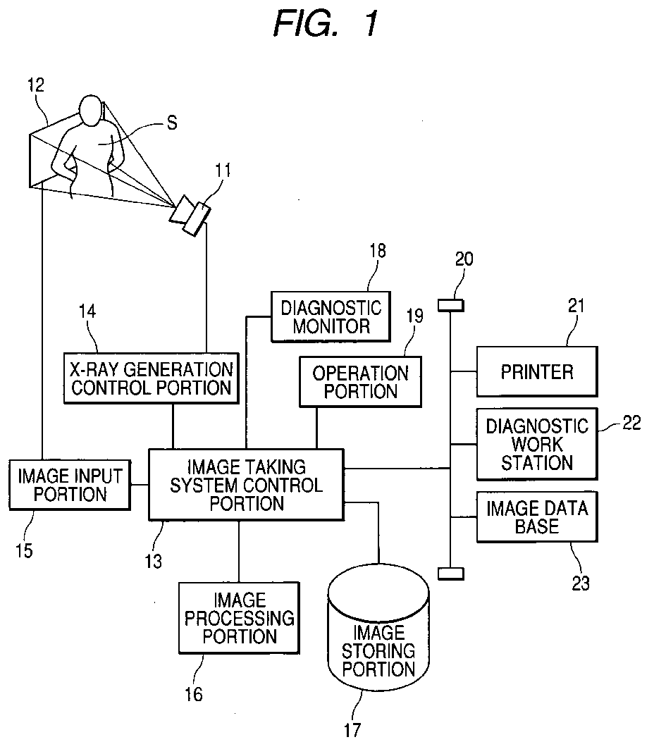
- An X-ray source 11 and an X-ray detector 12 are disposed with a subject S which is a patient interposed therebetween, and the output of an image taking system control portion 13 is connected to the X-ray source 11 through an X-ray generation control portion 14. Also, the output of the X-ray detector 12 is connected to the image taking system control portion 13 through an image input portion 15.
- an image processing portion 16 an image storing portion 17, a diagnostic monitor 18, an operation portion 19 and a network 20 are connected to the image taking system control portion 13, and a printer 21, a diagnostic work station 22 and an image data base 23 are connected to the network 20.
- An X-ray generated from the X-ray source 11 controlled by the X-ray generation control portion 14 is transmitted through the subject S which is a patient and is detected by the X-ray detector 12, and the detected X-ray is inputted as a projection image to the image input portion 15 through the image taking system control portion 13.
- the X-ray source 11 and the X-ray detector 12 effect the collection of the projection image at each rotation angle while effecting rotation with the subject S as a rotation center.
- a subject S fixed onto a rotary table may be rotated while the positional relationship between the X-ray source 11 and the X-ray detector 12 is kept.
- the inputted projection image of each rotational angle is subjected to image processing such as the correction of the X-ray detector 12, anti-processing including logarithmic conversion and reconstruction processing by the image processing portion 16, and a tomographic image group is prepared.
- image processing such as the correction of the X-ray detector 12, anti-processing including logarithmic conversion and reconstruction processing by the image processing portion 16, and a tomographic image group is prepared.
- the prepared tomographic image group is displayed on the diagnostic monitor 18, is stored in the image storing portion 17, or is outputted to the printer 21, the diagnostic work station 22 and the image data base 23 through the network 20.
- Various operations such as a window operation for display, the changeover display operation of a tomographic image in a body axis direction, a cross-section converting operation and a three-dimensional surface display operation are performed by the operation portion 19.
- Fig. 2 shows an illustration of the operation in this system, and the error of opposite fan beams with respect to projection data, i.e., the degree of consistency, is obtained for each projection angle from a sinogram, and a region in which this greess of consistency is within the reference is obtained, and an effective projection angle region is determined therefrom, and reconstruction is effected by the use of projection data in this region of reference error.
- Step 1 a sinogram is prepared.
- the sinogram is an image in which projection data are arranged with the axis of abscissas as the fan angle ⁇ or channel direction of the X-ray detector 12, and the axis of ordinates as the projection angle direction of the X-ray source 11.
- a detector row of a particular position is used in the body axis direction.
- This particular position can be, for example, a position coincident with the center axis of an X-ray beam.
- sinograms may be prepared at a plurality of positions and up to a step 4 may be executed, and an effective projection angle common at all the positions may be determined as an effective projection angle.
- Step 2 the projection data of the opposite fan beams is prepared for each projection angle from the sinogram.
- the X-ray transmission route of a fan angle ⁇ coincides with an X-ray transmission route of which the fan angle is - ⁇ .
- the transmission value g( ⁇ , ⁇ ) of the transmission route is coincident with g(- ⁇ , ⁇ + ⁇ +2 ⁇ ) and the data of g(- ⁇ , ⁇ + ⁇ +2 ⁇ ) has its projection angle digitized and therefore, actually the projection data does not always exist on ⁇ + ⁇ +2 ⁇ .
- projection data is prepared from the preceding and succeeding projection data by interpolation.
- the g( ⁇ , ⁇ ) and g(- ⁇ , ⁇ + ⁇ +2 ⁇ ) can be represented as one-dimensional vector data at each digitized projection angle ⁇ i.
- These one-dimensional vector data are set as g ⁇ i ( ⁇ j ) and [g ⁇ i ( ⁇ j )], respectively.
- ⁇ j and [ ⁇ j ] correspond to each other and ⁇ i and [ ⁇ i ] correspond to each other, and these g ⁇ i ( ⁇ j ) and [g ⁇ i ( ⁇ j )] are data which should originally coincide with each other.
- Step 3 the degree of consistency of the opposite fan beams with the projection data is obtained for each projection angle.
- This degree of consistency refers to the degree of coincidence between g ⁇ i ( ⁇ j ) and [g ⁇ i ( ⁇ j )]. That is, the degree of coincidence between g ⁇ i ( ⁇ j ) and [g ⁇ i ( ⁇ j )] being high means that the error between g ⁇ i ( ⁇ j ) and [g ⁇ i ( ⁇ j )] is small.
- Step 4 the region of reference error of the degree of consistency is obtained, and the projection angle region is determined from this region of reference error.
- the absolute value error E obtained at the step 3 is a one-dimensional vector with ⁇ i or [ ⁇ i ] as an index.
- Fig. 3 shows the absolute value error E obtained from two sinograms, and the axis of abscissas represents the projection angle, and when the fan angle is defined as ⁇ , it can be prepared in a region of 0 to ⁇ -2 ⁇ .
- a region in which the absolute value error E of the axis of ordinates is smaller than a predetermined reference error is obtained and is defined as a region of reference error.
- g ⁇ and g ⁇ + ⁇ can be regarded as being coincident with each other up to 0- ⁇ , and in ⁇ + ⁇ and thereafter, they can be regarded as being not coincident with each other at all angles. This leads to the presumption that there has been a change in body movement or the like at a point whereat shift occurs from ⁇ to ⁇ + ⁇ or from ⁇ + ⁇ to ⁇ + ⁇ + ⁇ .
- the effective region of the projection angle determined here is smaller than ⁇ +2 ⁇ , it means that the projection data necessary for reconstruction are not complete, and image taking can be regarded as having failed. If this judgment is effected at real time in parallel with image taking, it will be possible to discontinue the image taking and prevent excess X-ray exposure at the point whereat the image taking has been judged to have failed. Such judgment can likewise be applied to a case where the effective region is of such a pattern as shown in Fig. 7A and Fig. 7B.
- Step 5 the projection data in the projection angle region obtained at the step 4 is reconstructed to thereby prepare a tomographic image.
- the tomographic image can be reconstructed if in principle, there is projection data of 180 degrees + fan angle or greater.
- projection data of 180 degrees + fan angle In a case of a method when use is made of projection data of 180 degrees + fan angle to 360 degrees, and in 360 degrees scanning, all projection angle data overlap one another, but when reconstruction is to be effected by the use of projection data of less than 360 degrees, there are overlapping projection angles and non-overlapping projection angles and therefore, if the weight of the overlapping projection data is adjusted, normal reconstruction will be possible.
Landscapes
- Health & Medical Sciences (AREA)
- Life Sciences & Earth Sciences (AREA)
- Engineering & Computer Science (AREA)
- Medical Informatics (AREA)
- Optics & Photonics (AREA)
- Biomedical Technology (AREA)
- Biophysics (AREA)
- High Energy & Nuclear Physics (AREA)
- Veterinary Medicine (AREA)
- Nuclear Medicine, Radiotherapy & Molecular Imaging (AREA)
- Public Health (AREA)
- Pathology (AREA)
- Radiology & Medical Imaging (AREA)
- Physics & Mathematics (AREA)
- Heart & Thoracic Surgery (AREA)
- Molecular Biology (AREA)
- Surgery (AREA)
- Animal Behavior & Ethology (AREA)
- General Health & Medical Sciences (AREA)
- Pulmonology (AREA)
- Theoretical Computer Science (AREA)
- Apparatus For Radiation Diagnosis (AREA)
- Analysing Materials By The Use Of Radiation (AREA)
Abstract
Description
- This invention relates to an X-ray CT apparatus for reconstructing a tomographic image by the use of projection data.
- In an X-ray CT (computer tomography) apparatus, there is practiced half scan reconstruction which reconstructs an image by the use of projection data of 180 degrees + fan angle without the use of projection data corresponding to one full rotation. Further, it is also known that when use is made of projection data of 180 degrees + fan angle to 360 degrees, reconstruction can be done by a similar method as disclosed in Japanese Patent Application Laid-Open No. 2001-299738.
- Describing this by the use of sinogram, in a system construction by an
X-ray detector 2 opposed to an X-ray source 1 shown in Fig. 9 of the accompanying drawings with a subject S interposed therebetween, a sinogram is an image formed by projection data arranged with the fan angle or channel direction of theX-ray detector 2 as the axis of abscissas and the projection angle direction of the X-ray source 1 as the axis of ordinates, as shown in Fig. 10 of the accompanying drawings. Herein, description is made with respect to anarcuate X-ray detector 2 and therefore, the axis of abscissas is the fan angle, but in the case of alinear X-ray detector 2, conversion from distance to angle is necessary. - In a case where a fan beam is used as the X-ray source 1, as shown in Fig. 11 of the accompanying drawings, an X-ray transmission route of a fan angle α coincides with an X-ray transmission route of which the fan angle is -α when a projection angle is rotated by 180 degrees +2α . This means that assuming that the transmission data value of a transmission route of a fan angle α and a projection angle β is g(α,β), the transmission data value g(-α,π+β+2α) of a transmission route opposed thereto coincides therewith. That is, g(α,β)= g(-α,π+β+2α). This is represented on the sinogram as shown in Fig. 12 of the accompanying drawings.
- Thereby, it will be seen that when the projection angle is 0 degree to 180 degrees +2δ (δ being the one side maximum angle of the fan), a gray portion shown in Fig. 13 of the accompanying drawings is dually overlapping data. Thus, if this overlapping data portion is corrected by a weighting factor so as to become the same weight as a non-duplicate portion, it can be normally reconstructed.
- Even in the case of a projection angle greater than 180 degrees + fan angle α, reconstruction can be accomplished by the use of a weighting factor as in half scan reconstruction.
- The reconstruction used in the actual CT system is either full scan reconstruction using projection data fully 360 degrees or half scan reconstruction using projection data of 180 degrees + fan angle α. In the case of the half scan reconstruction, projection data used for the reconstruction is substantially a half and therefore, the quality of image is insufficient.
- Also, in the case of full scan reconstruction, projection data used becomes double and correspondingly, the time required for image taking becomes double, and the risk of an inconvenience such as, for example, body movement or the fluctuation of the quality of X-ray occurring during scanning becomes high, and if such inconvenience occurs, a construction may occur to the projection data and in some cases, an artifact may occur or the deterioration of the quality of image may occur.
- Reconstruction in a case when use is made of projection data of a 0 degree - 180 degrees + fan angle α to 360 degrees is also known, but no consideration is given to what range of projection data should be used.
- The present invention has been made in view of the above-noted problems and provides a technique relating to an X-ray CT apparatus which reduces the influence of body movement, the fluctuation of the quality of X-ray or the like upon image taking.
- In order to solve the above-noted problems, an X-ray CT image taking apparatus for obtaining a reconstructed image from projection data obtained from X-ray image taking which is one aspect of the present invention is characterized by the provision of:
- calculation means for obtaining the degree of consistency of projection data opposed to the projection data of a projection angle at each projection angle;
- determination means for determining the effective region of the projection angle by the use of the degree of consistency obtained by the calculation means; and
- tomographic image forming means for reconstructing an image by the use of the projection data within the effective region determined by the determination means to thereby obtain a tomographic image.
-
- Other features and advantages of the present invention will become apparent from the following description taken in conjunction with the accompanying drawings, in which like reference characters designate the same or similar parts throughout the figures thereof.
- The accompanying drawings, which are incorporated in and constitute a part of the specification, an illustrate embodiment of the invention and, together with the description, serve to explain the principles of the invention.
- Fig. 1 shows the construction of an X-ray CT system according to an embodiment of the present invention.
- Fig. 2 is an illustration for obtaining the region of reference error of a projection angle from sinogram.
- Fig. 3 is an illustration for obtaining the region of reference error of projection data.
- Figs. 4A and 4B are illustrations for obtaining an effective projection angle region from the region of reference error.
- Fig. 5 is an illustration by the sinogram of a projection angle in which there has been a change.
- Fig. 6 is an illustration by the sinogram of the effective projection angle region.
- Figs. 7A and 7B are illustrations of the pattern of an effective region.
- Fig. 8 is an illustration of the pattern of an effective region.
- Fig. 9 shows the construction of the X-ray CT system.
- Fig. 10 is an illustration of the sinogram.
- Fig. 11 is an illustration of opposite projection data.
- Fig. 12 is an illustration of the opposite projection data by a sinogram.
- Fig. 13 is an illustration of overlapping projection data by a sinogram.
-
- Preferred embodiment of the present invention will hereinafter be described in detail in accordance with the accompanying drawings.
- The present invention will now be described in detail with respect to the shown embodiments thereof.
- Fig. 1 shows the construction of an X-ray CT system according to Embodiment 1. An
X-ray source 11 and anX-ray detector 12 are disposed with a subject S which is a patient interposed therebetween, and the output of an image takingsystem control portion 13 is connected to theX-ray source 11 through an X-raygeneration control portion 14. Also, the output of theX-ray detector 12 is connected to the image takingsystem control portion 13 through animage input portion 15. Further, animage processing portion 16, animage storing portion 17, adiagnostic monitor 18, anoperation portion 19 and a network 20 are connected to the image takingsystem control portion 13, and aprinter 21, adiagnostic work station 22 and animage data base 23 are connected to the network 20. - An X-ray generated from the
X-ray source 11 controlled by the X-raygeneration control portion 14 is transmitted through the subject S which is a patient and is detected by theX-ray detector 12, and the detected X-ray is inputted as a projection image to theimage input portion 15 through the image takingsystem control portion 13. TheX-ray source 11 and theX-ray detector 12 effect the collection of the projection image at each rotation angle while effecting rotation with the subject S as a rotation center. Alternatively, a subject S fixed onto a rotary table may be rotated while the positional relationship between theX-ray source 11 and theX-ray detector 12 is kept. - The inputted projection image of each rotational angle is subjected to image processing such as the correction of the
X-ray detector 12, anti-processing including logarithmic conversion and reconstruction processing by theimage processing portion 16, and a tomographic image group is prepared. The prepared tomographic image group is displayed on thediagnostic monitor 18, is stored in theimage storing portion 17, or is outputted to theprinter 21, thediagnostic work station 22 and theimage data base 23 through the network 20. Various operations such as a window operation for display, the changeover display operation of a tomographic image in a body axis direction, a cross-section converting operation and a three-dimensional surface display operation are performed by theoperation portion 19. - Fig. 2 shows an illustration of the operation in this system, and the error of opposite fan beams with respect to projection data, i.e., the degree of consistency, is obtained for each projection angle from a sinogram, and a region in which this greess of consistency is within the reference is obtained, and an effective projection angle region is determined therefrom, and reconstruction is effected by the use of projection data in this region of reference error.
- In order to carry out this, the procedure of the steps in the following items (1) to (5).
- The sinogram, as shown in Fig. 10, is an image in which projection data are arranged with the axis of abscissas as the fan angle α or channel direction of the
X-ray detector 12, and the axis of ordinates as the projection angle direction of theX-ray source 11. - When a two-dimensional plane detector is used as the
X-ray detector 12, a detector row of a particular position is used in the body axis direction. This particular position can be, for example, a position coincident with the center axis of an X-ray beam. - Alternatively, sinograms may be prepared at a plurality of positions and up to a step 4 may be executed, and an effective projection angle common at all the positions may be determined as an effective projection angle.
- In a case where a fan beam is used as the
X-ray Source 11, when the projection angle is rotated by 180 degrees +2α, as shown in Fig. 11, the X-ray transmission route of a fan angle α coincides with an X-ray transmission route of which the fan angle is -α. As illusted in Fig. 12, the transmission value g(α,β) of the transmission route is coincident with g(-α,π+β +2α) and the data of g(-α,π+β +2α) has its projection angle digitized and therefore, actually the projection data does not always exist on π+β+2α. In that case, projection data is prepared from the preceding and succeeding projection data by interpolation. The g(α,β) and g(-α,π+β+2α) can be represented as one-dimensional vector data at each digitized projection angle βi. - These one-dimensional vector data are set as gβi(αj) and [gβi(αj)], respectively. Here, αj and [αj] correspond to each other and βi and [βi] correspond to each other, and these gβi(αj) and [gβi(αj)] are data which should originally coincide with each other.
- This degree of consistency refers to the degree of coincidence between gβi(αj) and [gβi(αj)]. That is, the degree of coincidence between gβi(αj) and [gβi(αj)] being high means that the error between gβi(αj) and [gβi(αj)] is small.
- So, as an index of the degree of consistency, use can be made of the average square error E of gβi(αj) and [gβi(αj)]. This can be obtained by varying j by the expression that E = √Σ{gβi(αj)-[gβi(αj)]}2. Of course, the square root need not be obtained, but simply use may be made of an absolute value error E = |Σ{gβi(αj)-[gβi(αj)]}|. The smaller are the average square error and the absolute value error E, the higher becomes the degree of consistency.
- The absolute value error E obtained at the step 3 is a one-dimensional vector with βi or [βi] as an index. Fig. 3 shows the absolute value error E obtained from two sinograms, and the axis of abscissas represents the projection angle, and when the fan angle is defined as δ, it can be prepared in a region of 0 to π-2δ. A region in which the absolute value error E of the axis of ordinates is smaller than a predetermined reference error is obtained and is defined as a region of reference error.
- Next, the effective projection angle region of Fig. 4B which can be regarded as normal image taking having been effected is determined from the region of reference error of Fig. 4A.
- Here, assuming that as shown, for example, in Fig. 3, the region of reference error has been obtained as 0-γ, at this time, as shown in Fig. 5, gγ and gγ+π can be regarded as being coincident with each other up to 0-γ, and in γ+Δβ and thereafter, they can be regarded as being not coincident with each other at all angles. This leads to the presumption that there has been a change in body movement or the like at a point whereat shift occurs from γ to γ+Δβ or from γ+π to γ+Δβ+π.
- Here, assuming that γ+π exceeds γ+2δ and there has been a change at the point whereat shift occurs from γ to γ+Δβ, incoincidence occurs before γ and therefore, it can be presumed that the change has occurred not at the point whereat shift occurs from γ to γ+Δβ, but at the point at which shift occurs from γ+π to γ+Δβ+π.
- However, the point at which shift occurs from γ+π to γ+Δβ+π has a width of 4δ as actual projection data and cannot be intactly identified and therefore, as shown in Fig. 6, the degree of consistency of the projection data in the region of γ+π-2δ to γ+π+2δ+Δβ and projection data opposite thereto is evaluated as previously described, whereby an effective projection angle region can be determined.
- Also when γ+π has not exceeded π+2δ, the degree of consistency by the projection data in the region of γ+π-2δ to γ+π+2δ+Δβ and the projection data opposite thereto is likewise evaluated, whereby effective projection angle region can be determined.
- However, if the effective region of the projection angle determined here is smaller than π+2δ, it means that the projection data necessary for reconstruction are not complete, and image taking can be regarded as having failed. If this judgment is effected at real time in parallel with image taking, it will be possible to discontinue the image taking and prevent excess X-ray exposure at the point whereat the image taking has been judged to have failed. Such judgment can likewise be applied to a case where the effective region is of such a pattern as shown in Fig. 7A and Fig. 7B.
- In the case of a pattern as shown in Fig. 8 wherein gγ and gγ+π are not coincident only at a certain projection angle γ, it can be judged that abnormality is present in the data of the projection angle γ, and projection angles except the projection angle γ can be used as the effective region of the projection angle. In the other cases, the effective region can be considered in a combination of Figs. 7 and 8.
- The tomographic image can be reconstructed if in principle, there is projection data of 180 degrees + fan angle or greater. In a case of a method when use is made of projection data of 180 degrees + fan angle to 360 degrees, and in 360 degrees scanning, all projection angle data overlap one another, but when reconstruction is to be effected by the use of projection data of less than 360 degrees, there are overlapping projection angles and non-overlapping projection angles and therefore, if the weight of the overlapping projection data is adjusted, normal reconstruction will be possible.
- In this manner, there can be prepared a tomographic image using projection data in a normally scanned region.
- As described above, according to each embodiment, use is made of projection data in the effective region and therefore, there can be provided a technique regarding an X-ray CT apparatus which reduceds the influence of body movement, the fluctuation or the like of the quality of X-ray upon image taking.
- As many apparently widely different embodiments of the present invention can be made without departing from the spirit and scope thereof, it is to be understood that the invention is not limited to the specific embodiment thereof except as defined in the appended claims.
Claims (7)
- An X-ray CT image taking apparatus for obtaining a reconstructed image from projection data obtained by X-ray image taking, provided with:calculation means for obtaining the degree of consistency of projection data opposite to the projection data of a projection angle at each projection angle;determination means for determining the effective region of said projection angle by the use of said degree of consistency obtained by said calculation means; andtomographic image forming means for reconstructing an image by the use of said projection data in said effective region determined by said determination means to thereby obtain a tomographic image.
- An X-ray CT image taking apparatus according to Claim 1, wherein said degree of consistency has an error between said projection data and said opposite projection data as an evaluated amount.
- An X-ray CT image taking apparatus according to Claim 1, wherein said opposite projection data is obtained by being prepared by interpolation.
- An X-ray CT image taking apparatus according to Claim 1, wherein the determination of said effective region is effected by obtaining a region in which the degree of consistency of said projection data opposite to said projection data is within a reference to thereby determine the effective region of said projection angle from said region of reference error.
- An X-ray CT image taking apparatus according to Claim 1, wherein the judgment of the effective region of said projection angle is effected in parallel with said X-ray image taking, and if the effective region of said projection angle is less than an angle of a fan angle plus 180 degrees, said X-ray image taking is discontinued.
- An X-ray CT image taking apparatus according to Claim 1, wherein when said projection data overlaps in said effective region, the weight of the overlapping projection data is adjusted.
- An X-ray CT image taking method of obtaining a reconstructed image from projection data obtained by X-ray image taking, provided with:the calculating step of obtaining the degree of consistency of projection data opposite to the projection data of a projection angle at each projection angle;the determining step of determining the effective region of said projection angle by the use of said degree of consistency obtained by said calculating step; andthe tomographic image forming step of reconstructing an image by the use of said projection data in said effective region determined by said determining step to thereby obtain a tomographic image.
Applications Claiming Priority (2)
| Application Number | Priority Date | Filing Date | Title |
|---|---|---|---|
| JP2004177404 | 2004-06-15 | ||
| JP2004177404A JP4498023B2 (en) | 2004-06-15 | 2004-06-15 | X-ray CT system |
Publications (2)
| Publication Number | Publication Date |
|---|---|
| EP1609419A1 true EP1609419A1 (en) | 2005-12-28 |
| EP1609419B1 EP1609419B1 (en) | 2010-02-24 |
Family
ID=35116015
Family Applications (1)
| Application Number | Title | Priority Date | Filing Date |
|---|---|---|---|
| EP05012234A Expired - Lifetime EP1609419B1 (en) | 2004-06-15 | 2005-06-07 | X-ray CT image taking apparatus and X-ray CT image taking method |
Country Status (6)
| Country | Link |
|---|---|
| US (1) | US7145979B2 (en) |
| EP (1) | EP1609419B1 (en) |
| JP (1) | JP4498023B2 (en) |
| KR (1) | KR100684303B1 (en) |
| CN (1) | CN100524018C (en) |
| DE (1) | DE602005019497D1 (en) |
Cited By (2)
| Publication number | Priority date | Publication date | Assignee | Title |
|---|---|---|---|---|
| FR2924325A1 (en) * | 2007-12-03 | 2009-06-05 | Trophy Soc Par Actions Simplif | Dental X-ray apparatus i.e. cone beam computed tomography apparatus, for e.g. dental quadrant, has sensor oriented such that longitudinal axis is perpendicular to surface, where center of sensor is shifted relative to projection of axis |
| US8979364B2 (en) | 2009-05-04 | 2015-03-17 | Trophy | Combined panoramic and computed tomography apparatus |
Families Citing this family (11)
| Publication number | Priority date | Publication date | Assignee | Title |
|---|---|---|---|---|
| JP4438053B2 (en) * | 2004-05-11 | 2010-03-24 | キヤノン株式会社 | Radiation imaging apparatus, image processing method, and computer program |
| JP2006000225A (en) * | 2004-06-15 | 2006-01-05 | Canon Inc | X-ray CT system |
| JP4769441B2 (en) * | 2004-08-19 | 2011-09-07 | キヤノン株式会社 | Image processing apparatus and image processing method |
| JP4585815B2 (en) * | 2004-09-03 | 2010-11-24 | キヤノン株式会社 | Information processing apparatus, imaging system, absorption coefficient correction method, and computer program |
| US7515917B2 (en) | 2005-07-12 | 2009-04-07 | Qwest Communications International Inc. | Efficiently determining the location of a mobile communications device system and methods |
| KR100837750B1 (en) * | 2006-08-25 | 2008-06-13 | 엔에이치엔(주) | How to search Chinese using tonal and system to perform the above method |
| JP2008253569A (en) * | 2007-04-05 | 2008-10-23 | Rigaku Corp | Abnormal body motion detection device and abnormal body motion detection method |
| JP5366390B2 (en) * | 2007-11-06 | 2013-12-11 | 株式会社東芝 | X-ray equipment |
| DE102009009617B4 (en) * | 2009-02-19 | 2019-04-25 | Siemens Healthcare Gmbh | Method and device for improving the image quality during image determination by iterative reconstruction |
| JP2011136027A (en) * | 2009-12-28 | 2011-07-14 | Nihon Univ | X-ray ct imaging apparatus, and reconfiguration processing method |
| US10064546B2 (en) * | 2012-10-24 | 2018-09-04 | Nidek Co., Ltd. | Ophthalmic analysis apparatus and ophthalmic analysis program |
Citations (3)
| Publication number | Priority date | Publication date | Assignee | Title |
|---|---|---|---|---|
| EP0430549A2 (en) * | 1989-11-22 | 1991-06-05 | General Electric Company | Helical scan computed tomography |
| US20020025017A1 (en) * | 1999-06-17 | 2002-02-28 | Stergios Stergiopoulos | Method for tracing organ motion and removing artifacts for computed tomography imaging systems |
| WO2004010383A2 (en) * | 2002-07-23 | 2004-01-29 | General Electric Company | Method and apparatus for deriving motion information from projection data |
Family Cites Families (11)
| Publication number | Priority date | Publication date | Assignee | Title |
|---|---|---|---|---|
| US5270923A (en) * | 1989-11-02 | 1993-12-14 | General Electric Company | Computed tomographic image reconstruction method for helical scanning using interpolation of partial scans for image construction |
| JP2970680B2 (en) * | 1990-06-14 | 1999-11-02 | 株式会社東芝 | X-ray CT system |
| JP2760781B2 (en) * | 1996-01-31 | 1998-06-04 | 株式会社東芝 | X-ray tomography equipment |
| US5671263A (en) * | 1996-03-13 | 1997-09-23 | Analogic Corporation | Motion artifact suppression filter for use in computed tomography systems |
| US5708690A (en) * | 1996-10-11 | 1998-01-13 | General Electric Company | Methods and apparatus for helical image reconstruction in a computed tomography fluoro system |
| US5960056A (en) * | 1997-07-01 | 1999-09-28 | Analogic Corporation | Method and apparatus for reconstructing volumetric images in a helical scanning computed tomography system with multiple rows of detectors |
| JP3124254B2 (en) * | 1997-07-24 | 2001-01-15 | ジーイー横河メディカルシステム株式会社 | Radiation tomography equipment |
| US6108575A (en) * | 1998-02-20 | 2000-08-22 | General Electric Company | Helical weighting algorithms for fast reconstruction |
| US6324247B1 (en) * | 1999-12-30 | 2001-11-27 | Ge Medical Systems Global Technology Company, Llc | Partial scan weighting for multislice CT imaging with arbitrary pitch |
| DE10123797B4 (en) * | 2001-05-16 | 2006-10-19 | Siemens Ag | Method for producing an image with a computer tomograph |
| JP4282302B2 (en) * | 2001-10-25 | 2009-06-17 | 株式会社東芝 | X-ray CT system |
-
2004
- 2004-06-15 JP JP2004177404A patent/JP4498023B2/en not_active Expired - Fee Related
-
2005
- 2005-06-01 US US11/140,898 patent/US7145979B2/en not_active Expired - Fee Related
- 2005-06-07 EP EP05012234A patent/EP1609419B1/en not_active Expired - Lifetime
- 2005-06-07 DE DE602005019497T patent/DE602005019497D1/en not_active Expired - Lifetime
- 2005-06-14 CN CNB2005100780911A patent/CN100524018C/en not_active Expired - Fee Related
- 2005-06-15 KR KR1020050051354A patent/KR100684303B1/en not_active Expired - Fee Related
Patent Citations (3)
| Publication number | Priority date | Publication date | Assignee | Title |
|---|---|---|---|---|
| EP0430549A2 (en) * | 1989-11-22 | 1991-06-05 | General Electric Company | Helical scan computed tomography |
| US20020025017A1 (en) * | 1999-06-17 | 2002-02-28 | Stergios Stergiopoulos | Method for tracing organ motion and removing artifacts for computed tomography imaging systems |
| WO2004010383A2 (en) * | 2002-07-23 | 2004-01-29 | General Electric Company | Method and apparatus for deriving motion information from projection data |
Non-Patent Citations (1)
| Title |
|---|
| WESARG STEFAN ET AL: "Parker weights revisited", MEDICAL PHYSICS, AMERICAN INSTITUTE OF PHYSICS. NEW YORK, US, vol. 29, no. 3, March 2002 (2002-03-01), pages 372 - 378, XP012011740, ISSN: 0094-2405 * |
Cited By (4)
| Publication number | Priority date | Publication date | Assignee | Title |
|---|---|---|---|---|
| FR2924325A1 (en) * | 2007-12-03 | 2009-06-05 | Trophy Soc Par Actions Simplif | Dental X-ray apparatus i.e. cone beam computed tomography apparatus, for e.g. dental quadrant, has sensor oriented such that longitudinal axis is perpendicular to surface, where center of sensor is shifted relative to projection of axis |
| WO2009101283A3 (en) * | 2007-12-03 | 2009-10-29 | Trophy | Dental x-ray apparatus and associated method |
| US8363780B2 (en) | 2007-12-03 | 2013-01-29 | Trophy | Dental X-ray apparatus and associated method |
| US8979364B2 (en) | 2009-05-04 | 2015-03-17 | Trophy | Combined panoramic and computed tomography apparatus |
Also Published As
| Publication number | Publication date |
|---|---|
| DE602005019497D1 (en) | 2010-04-08 |
| CN1713073A (en) | 2005-12-28 |
| KR100684303B1 (en) | 2007-02-20 |
| JP4498023B2 (en) | 2010-07-07 |
| US20050276371A1 (en) | 2005-12-15 |
| KR20060049601A (en) | 2006-05-19 |
| US7145979B2 (en) | 2006-12-05 |
| CN100524018C (en) | 2009-08-05 |
| EP1609419B1 (en) | 2010-02-24 |
| JP2006000224A (en) | 2006-01-05 |
Similar Documents
| Publication | Publication Date | Title |
|---|---|---|
| US6292530B1 (en) | Method and apparatus for reconstructing image data acquired by a tomosynthesis x-ray imaging system | |
| US7778386B2 (en) | Methods for analytic reconstruction for mult-source inverse geometry CT | |
| US7145979B2 (en) | X-ray CT image taking apparatus and X-ray CT image taking method | |
| US6452996B1 (en) | Methods and apparatus utilizing generalized helical interpolation algorithm | |
| JP4360817B2 (en) | Radiation tomography equipment | |
| US6256370B1 (en) | Method and apparatus for performing tomosynthesis | |
| JP4465062B2 (en) | Computerized tomography system | |
| EP0430549B1 (en) | Helical scan computed tomography | |
| WO1995022115A1 (en) | Reconstruction of images from cone beam data | |
| JPH09224930A (en) | System for generating tomographic images of an object and volumetric computer tomography apparatus | |
| JP2001161678A (en) | Cone beam multi-slice type CT correction method and apparatus | |
| IL116572A (en) | Image reconstruction for a ct system implementing a dual fan beam helical scan | |
| IL116257A (en) | Helical interpolative algorithm for image reconstruction in a ct system | |
| US5469487A (en) | CT system with twin fan beam helical scan | |
| WO2000062674A1 (en) | Half field of view reduced-size ct detector | |
| US5974110A (en) | Helical reconstruction algorithm | |
| US7555096B2 (en) | X-ray CT apparatus and image-taking method therefor | |
| US20090080595A1 (en) | Computed tomography system | |
| US6278762B1 (en) | Systems, methods and apparatus for reconstructing images | |
| US7809100B2 (en) | Rebinning for computed tomography imaging | |
| JPH11197146A (en) | Detector for computed tomography system | |
| JP2010184086A (en) | Radiographic ct apparatus, and its control method | |
| JP3802650B2 (en) | X-ray CT system | |
| JP5387018B2 (en) | X-ray tomography system | |
| US6463117B1 (en) | Methods and apparatus for tilted helical image reconstruction in CT imaging |
Legal Events
| Date | Code | Title | Description |
|---|---|---|---|
| PUAI | Public reference made under article 153(3) epc to a published international application that has entered the european phase |
Free format text: ORIGINAL CODE: 0009012 |
|
| AK | Designated contracting states |
Kind code of ref document: A1 Designated state(s): AT BE BG CH CY CZ DE DK EE ES FI FR GB GR HU IE IS IT LI LT LU MC NL PL PT RO SE SI SK TR |
|
| AX | Request for extension of the european patent |
Extension state: AL BA HR LV MK YU |
|
| 17P | Request for examination filed |
Effective date: 20060628 |
|
| AKX | Designation fees paid |
Designated state(s): DE FR GB NL |
|
| GRAP | Despatch of communication of intention to grant a patent |
Free format text: ORIGINAL CODE: EPIDOSNIGR1 |
|
| GRAS | Grant fee paid |
Free format text: ORIGINAL CODE: EPIDOSNIGR3 |
|
| GRAA | (expected) grant |
Free format text: ORIGINAL CODE: 0009210 |
|
| AK | Designated contracting states |
Kind code of ref document: B1 Designated state(s): DE FR GB NL |
|
| REG | Reference to a national code |
Ref country code: GB Ref legal event code: FG4D |
|
| REF | Corresponds to: |
Ref document number: 602005019497 Country of ref document: DE Date of ref document: 20100408 Kind code of ref document: P |
|
| REG | Reference to a national code |
Ref country code: NL Ref legal event code: T3 |
|
| PLBE | No opposition filed within time limit |
Free format text: ORIGINAL CODE: 0009261 |
|
| STAA | Information on the status of an ep patent application or granted ep patent |
Free format text: STATUS: NO OPPOSITION FILED WITHIN TIME LIMIT |
|
| 26N | No opposition filed |
Effective date: 20101125 |
|
| PGFP | Annual fee paid to national office [announced via postgrant information from national office to epo] |
Ref country code: GB Payment date: 20130624 Year of fee payment: 9 Ref country code: DE Payment date: 20130630 Year of fee payment: 9 |
|
| PGFP | Annual fee paid to national office [announced via postgrant information from national office to epo] |
Ref country code: NL Payment date: 20130617 Year of fee payment: 9 |
|
| PGFP | Annual fee paid to national office [announced via postgrant information from national office to epo] |
Ref country code: FR Payment date: 20130718 Year of fee payment: 9 |
|
| REG | Reference to a national code |
Ref country code: DE Ref legal event code: R119 Ref document number: 602005019497 Country of ref document: DE |
|
| REG | Reference to a national code |
Ref country code: NL Ref legal event code: V1 Effective date: 20150101 |
|
| GBPC | Gb: european patent ceased through non-payment of renewal fee |
Effective date: 20140607 |
|
| REG | Reference to a national code |
Ref country code: DE Ref legal event code: R119 Ref document number: 602005019497 Country of ref document: DE Effective date: 20150101 |
|
| REG | Reference to a national code |
Ref country code: FR Ref legal event code: ST Effective date: 20150227 |
|
| PG25 | Lapsed in a contracting state [announced via postgrant information from national office to epo] |
Ref country code: NL Free format text: LAPSE BECAUSE OF NON-PAYMENT OF DUE FEES Effective date: 20150101 |
|
| PG25 | Lapsed in a contracting state [announced via postgrant information from national office to epo] |
Ref country code: DE Free format text: LAPSE BECAUSE OF NON-PAYMENT OF DUE FEES Effective date: 20150101 |
|
| PG25 | Lapsed in a contracting state [announced via postgrant information from national office to epo] |
Ref country code: GB Free format text: LAPSE BECAUSE OF NON-PAYMENT OF DUE FEES Effective date: 20140607 Ref country code: FR Free format text: LAPSE BECAUSE OF NON-PAYMENT OF DUE FEES Effective date: 20140630 |