EP1609213B1 - Antenne dielectriquement chargee - Google Patents
Antenne dielectriquement chargee Download PDFInfo
- Publication number
- EP1609213B1 EP1609213B1 EP04720919A EP04720919A EP1609213B1 EP 1609213 B1 EP1609213 B1 EP 1609213B1 EP 04720919 A EP04720919 A EP 04720919A EP 04720919 A EP04720919 A EP 04720919A EP 1609213 B1 EP1609213 B1 EP 1609213B1
- Authority
- EP
- European Patent Office
- Prior art keywords
- elements
- antenna
- core
- group
- elongate
- Prior art date
- Legal status (The legal status is an assumption and is not a legal conclusion. Google has not performed a legal analysis and makes no representation as to the accuracy of the status listed.)
- Expired - Lifetime
Links
- 239000004020 conductor Substances 0.000 claims description 20
- 238000003780 insertion Methods 0.000 claims description 6
- 230000037431 insertion Effects 0.000 claims description 6
- 239000000463 material Substances 0.000 claims description 3
- 239000011343 solid material Substances 0.000 claims description 2
- 239000011162 core material Substances 0.000 description 28
- 230000000694 effects Effects 0.000 description 7
- 238000010586 diagram Methods 0.000 description 4
- 238000009795 derivation Methods 0.000 description 3
- 238000002955 isolation Methods 0.000 description 3
- 230000005540 biological transmission Effects 0.000 description 2
- 239000003989 dielectric material Substances 0.000 description 2
- 238000007747 plating Methods 0.000 description 2
- 238000010521 absorption reaction Methods 0.000 description 1
- 230000004323 axial length Effects 0.000 description 1
- 239000000919 ceramic Substances 0.000 description 1
- 239000002131 composite material Substances 0.000 description 1
- 238000010276 construction Methods 0.000 description 1
- 230000008878 coupling Effects 0.000 description 1
- 238000010168 coupling process Methods 0.000 description 1
- 238000005859 coupling reaction Methods 0.000 description 1
- 230000005284 excitation Effects 0.000 description 1
- 238000001914 filtration Methods 0.000 description 1
- 238000000034 method Methods 0.000 description 1
- 238000010295 mobile communication Methods 0.000 description 1
- 230000005855 radiation Effects 0.000 description 1
Images


Classifications
-
- H—ELECTRICITY
- H01—ELECTRIC ELEMENTS
- H01Q—ANTENNAS, i.e. RADIO AERIALS
- H01Q11/00—Electrically-long antennas having dimensions more than twice the shortest operating wavelength and consisting of conductive active radiating elements
- H01Q11/02—Non-resonant antennas, e.g. travelling-wave antenna
- H01Q11/08—Helical antennas
-
- H—ELECTRICITY
- H01—ELECTRIC ELEMENTS
- H01Q—ANTENNAS, i.e. RADIO AERIALS
- H01Q5/00—Arrangements for simultaneous operation of antennas on two or more different wavebands, e.g. dual-band or multi-band arrangements
- H01Q5/20—Arrangements for simultaneous operation of antennas on two or more different wavebands, e.g. dual-band or multi-band arrangements characterised by the operating wavebands
-
- H—ELECTRICITY
- H01—ELECTRIC ELEMENTS
- H01Q—ANTENNAS, i.e. RADIO AERIALS
- H01Q1/00—Details of, or arrangements associated with, antennas
- H01Q1/36—Structural form of radiating elements, e.g. cone, spiral, umbrella; Particular materials used therewith
-
- H—ELECTRICITY
- H01—ELECTRIC ELEMENTS
- H01Q—ANTENNAS, i.e. RADIO AERIALS
- H01Q1/00—Details of, or arrangements associated with, antennas
- H01Q1/36—Structural form of radiating elements, e.g. cone, spiral, umbrella; Particular materials used therewith
- H01Q1/38—Structural form of radiating elements, e.g. cone, spiral, umbrella; Particular materials used therewith formed by a conductive layer on an insulating support
-
- H—ELECTRICITY
- H01—ELECTRIC ELEMENTS
- H01Q—ANTENNAS, i.e. RADIO AERIALS
- H01Q5/00—Arrangements for simultaneous operation of antennas on two or more different wavebands, e.g. dual-band or multi-band arrangements
-
- H—ELECTRICITY
- H01—ELECTRIC ELEMENTS
- H01Q—ANTENNAS, i.e. RADIO AERIALS
- H01Q5/00—Arrangements for simultaneous operation of antennas on two or more different wavebands, e.g. dual-band or multi-band arrangements
- H01Q5/30—Arrangements for providing operation on different wavebands
- H01Q5/307—Individual or coupled radiating elements, each element being fed in an unspecified way
- H01Q5/342—Individual or coupled radiating elements, each element being fed in an unspecified way for different propagation modes
- H01Q5/357—Individual or coupled radiating elements, each element being fed in an unspecified way for different propagation modes using a single feed point
- H01Q5/364—Creating multiple current paths
- H01Q5/371—Branching current paths
-
- H—ELECTRICITY
- H01—ELECTRIC ELEMENTS
- H01Q—ANTENNAS, i.e. RADIO AERIALS
- H01Q7/00—Loop antennas with a substantially uniform current distribution around the loop and having a directional radiation pattern in a plane perpendicular to the plane of the loop
Definitions
- This invention relates to a dielectrically-loaded antenna for operation at frequencies in excess of 200MHz, and in particular to a loop antenna having a plurality of resonant frequencies within a band of operation.
- a dielectrically-loaded loop antenna is disclosed in British Patent Application No. 2309592A . Whilst this antenna has advantageous properties in terms of isolation from the structure on which it is mounted, its radiation pattern, and specific absorption ratio (SAR) performance when used on, for instance, a mobile telephone close to the user's head, it suffers from the generic problem of small antennas that it has insufficient bandwidth for many applications. Improved bandwidth can be achieved by splitting the radiating elements of the antenna into portions having different electrical lengths. For example, as disclosed in British Patent Application No. 2321785A , the individual helical radiating elements can each be replaced by a pair of mutually adjacent, substantially parallel, radiating elements connected at different positions to a linking conductor linking opposed radiating elements. In another variation, disclosed in British Patent Application No.
- the single helical elements are replaced by laterally opposed groups of elements, each group having a pair of coextensive mutually adjacent radiating elements in the form of parallel tracks having different widths to yield differing electrical lengths.
- a dielectrically-loaded antenna for operation at frequencies in excess of 200MHz, comprising an electrically insulative core of a solid material having a relative dielectric constant greater than 5, a feed connection, and an antenna element structure disposed on or adjacent the outer surface of the core, the material of the core occupying the major part of the volume defined by the core outer surface, wherein the antenna element structure comprises a pair of laterally opposed groups of conductive elongate elements, each group comprising first and second substantially coextensive elongate elements which have different electrical lengths at a frequency within an operating frequency band of the antenna and are coupled together at respective first ends at a location in the region of the feed connection and at respective second ends at a location spaced from the feed connection, the antenna element structure further comprising a linking conductor linking the second ends of the first and second elongate elements of one group with the second ends of the first and second elements of the other group, whereby the first elements of the two groups form part of a first looped conductive path, and
- the edge of the strip which is furthest from the other elongate element or elements in its group is longer than the edge which is nearer the other element or elements.
- both the first and second elongate elements of each group may have edges of different lengths, e.g., in that each such element which has an edge forming an outermost edge of the group is configured such that the outermost edge is longer than the inner edge of the element.
- each affected element may be a twisted loop antenna, with each group of elements executing a half turn around the central axis of a cylindrical dielectric core, the helical portion of each element has one edge which follows a strict helical path, whilst the other edge follows a path which deviates from the strict helical path in a sinusoid, castellated or smooth pattern, for example.
- the variations are equal for both edges at any given position along the length of the group of elements so that the overall width of the group at any given position is substantially the same.
- the outermost edges may be formed so as to be parallel along at least a major part of the length of the group of elements.
- Such structures take advantage of the discovery by the applicant that grouped and substantially coextensive radiating elements of different electrical lengths have fundamental modes of resonance corresponding not only to the individual elements which are close together, but also corresponding to the elements as a combination. Accordingly, where each group of elements has two substantially coextensive mutually adjacent elongate radiating elements, there exists a fundamental mode of resonance associated with one of the tracks, another fundametal resonance associated with the other of the tracks, and a third fundamental resonance associated with the composite element represented by the two tracks together. The frequency of the third resonance can be manipulated by asymmetrically altering the lengths of edges of the elements.
- the frequency of the third resonance can be altered differently, and to a greater degree, than the resonant frequencies associated with the individual tracks. It will be appreciated, therefore, that, the third frequency of resonance can be brought close to the other resonant frequencies so that all three couple together to form a wider band of reduced insertion loss than can be achieved with the above-described prior art antennas, at least for a given resonance type (i.e., in this case, the balanced modes of resonance in the preferred antenna).
- the elongate elements of each pair have different electrical lengths and define between them a parallel sided channel, each element having a meandered outer edge.
- each group of elongate antenna elements has three elongate elements, arranged side-by-side.
- each group comprises an inner element and two outer elements.
- the outwardly directed edges of the two outer elements of each group are meandered or otherwise caused to deviate from a path parallel to the corresponding inner edges, and the inner element is parallel-sided.
- at least one of the outer elements of each group has a deviating outer edge and a deviating inner edge, the amplitude of the outer edge deviation being greater than the amplitude of the inner edge deviation.
- Embodiments with three or more elements per group offer further bandwidth gains, in terms of fractional bandwidth and/or insertion loss.
- the antennas described above have particular application in the frequency division duplex portion of the IMT-2000 3-G receive and transmit bands (2110-2170MHz and 1920-1980MHz). They can also be applied to other mobile communication bands such as the GSM-1800 band (1710-1880MHz), the PCS1900 band (1850-1990MHz) and the Bluetooth LAN band (2401-2480MHz).
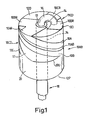
- an antenna of a construction similar to that shown in British Patent Application No. 2351850A has an antenna element structure comprising a pair of laterally opposed groups 10AB, 10CD of elongate radiating antenna elements 10AB, 10CD.
- the term "radiating” is used in this specification to describe antenna elements which, when the antenna is connected to a source of radio frequency energy, radiate energy into the space around the antenna. It will be understood that, in the context of an antenna for receiving radio frequency signals, the term “radiating elements” refers to elements which couple energy from the space surrounding the antenna to the conductors of the antenna for feeding to a receiver.
- Each group of elements comprises, in this embodiment, two coextensive, mutually adjacent and generally parallel elongate antenna elements 10A, 10B, 10C, 10D which are disposed on the outer cylindrical surface of an antenna core 12 made of a ceramic dielectric material having an relative dielectric constant greater than 5, typically 36 or higher.
- the core 12 has an axial passage 14 with an inner metallic lining, the passage 14 housing an axial inner feeder conductor 16 surrounded by a dielectric insulating sheath 17.
- the inner conductor 16 and the lining together form a coaxial feeder structure which passes axially through the core 12 from a distal end face 12D of the core to emerge as a coaxial transmission line 18 from a proximal end face 12P of the core 12.
- the antenna element structure includes corresponding radial elements 10AR, 10BR, 10CR, 10DR formed as conductive tracks on the distal end face 12D connecting distal ends of the elements 10A to 10D to the feeder structure.
- the elongate radiating elements 10A to 10D, including their corresponding radial portions, are of approximately the same physical length, and each includes a helical conductive track executing a half turn around the axis of the core 12.
- Each group of elements comprises a first element 10A, 10C of one width and a second element 10B, 10D of a different width. These differences in width cause differences in electrical lengths, due to the differences in wave velocity along the elements.
- each antenna element 10A to 10D is connected to the rim 20U of a common virtual ground conductor in the form of a conductive sleeve 20 surrounding a proximal end portion of the core 12 as a link conductor for the elements 10A to 10D.
- the sleeve 20 is, in turn, connected to the lining of the axial passage 14 by conductive plating on the proximal end face 12P of the core 12.
- a first 360 degrees conductive loop is formed by elements 10AR, 10A, rim 20U, and elements 10C and 10CR
- a second 360 degree conductive loop is formed by elements 10BR, 10B, the rim 20U, and elements 10D and 10DR.
- Each loop extends from one conductor of the feeder structure around the core to the other conductor of the feeder structure.
- the resonant frequency of one loop is slightly different from that of the other.
- the first and second antenna elements of the first group 10AB are substantially diametrically opposed to the corresponding first and second elements, respectively, of the second group 10C.
- the first ends of the helical portions of each conductive loop are approximately in the same plane as their second ends, the plane being a plane including the axis of the core 12.
- the circumferential spacing, i.e. the spacing around the core, between the neighbouring elements of each group is less than that between the groups.
- elements 10A and 10B are closer to each other than they are to the elements 10C, 10D.
- the conductive sleeve 20 covers a proximal portion of the antenna core 12, surrounding the feeder structure 18, the material of the core filing substantially the whole of the space between the sleeve 20 and the metallic lining of the axial passage 14.
- the combination of the sleeve 20 and plating forms a balun so that signals in the transmission line formed by the feeder structure 18 are converted between an unbalanced state at the proximal end of the antenna and a balanced state at an axial position above the plane of the upper edge 20U of the sleeve 20.
- the axial length of the sleeve is such that, in the presence of an underlying core material of relatively high dielectric constant, the balun has an electrical length of about ⁇ /4 or 90° in the operating frequency band of the antenna. Since the core material of the antenna has a foreshortening effect, the annular space surrounding the inner conductor is filled with an insulating dielectric material having a relatively small dielectric constant, the feeder structure 18 distally of the sleeve has a short electrical length. As a result, signals at the distal end of the feeder structure 18 are at least approximately balanced.
- a further effect of the sleeve 20 is that for frequencies in the region of the operating frequency of the antenna, the rim 20U of the sleeve 20 is effectively isolated from the ground represented by the outer conductor of the feeder structure. This means that currents circulating between the antenna elements 10A to 10D are confined substantially to the rim part. The sleeve thus acts as an isolating trap when the antenna is resonant in a balanced mode.
- the conductive loops formed by the elements also have different electrical lengths.
- the antenna resonates at two different resonant frequencies, the actual frequencies depending, in this case, on the widths of the elements.
- the generally parallel elements of each group extend from the region of the feed connection on the distal end face of the core to the rim 20U of the balun sleeve 20, thus defining an inter-element channel 11AB, 11 CD, or slit, between the elements of each group.
- the length of the channels are arranged to achieve substantial isolation of the conductive paths from one another at their respective resonant frequencies. This is achieved by forming the channels with an electrical length of ⁇ /2, or n ⁇ /2 where n is an odd integer. In effect, therefore, the electrical lengths of each of those edges of the conductors 10A to 10D bounding the channels 11AB, 11CD are also ⁇ /2 or n ⁇ /2.
- a standing wave is set up over the entire length of the resonant loop, with equal values of voltage being present at locations adjacent the ends of each ⁇ /2 channel, i.e. in the regions of the ends of the antenna elements.
- the antenna elements which form part of the non-resonating loop are isolated from the adjacent resonating elements, since equal voltages at either ends of the non-resonant elements result in zero current flow.
- the other conductive path is resonant, the other loop is likewise isolated from the resonating loop.
- excitation occurs in that path simultaneously with isolation from the other path. It follows that at least two quite distinct resonances are achieved at different frequencies due to the fact that each branch loads the conductive path of the other only minimally when the other is at resonance. In effect, two or more mutually isolated low impedance paths are formed around the core.
- the channels 11AB, 11CD are located in the main between the antenna elements 10A, 10B and 10C, 10D respectively, and by a relatively small distance into the sleeve 20. Typically, for each channel, the length of the channel part is located between the elements would be no less than 0.7L, where L is the total physical length of the channel.
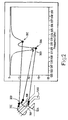
- Figure 1 which includes a graph plotting insertion loss (S11) with frequency and also shows a portion of one of the groups of antenna elements 10A, 10B where they meet the rim 20U of the sleeve 20 (see Figure 1).
- Each individual element 10A, 10B gives rise to a respective resonance 30A, 30B.
- the electrical lengths of the elements are such that these resonances are close together and are coupled.
- Each of these resonances has an associated current in the respective radiating element 10A, 10B which, in turn, induces a respective magnetic field 32A, 32B around the element 10A, 10B and passing through the slit 11AB, as shown in Figure 2.
- the coupling between the resonances 30A, 30B due to the individual tracks can be adjusted by adjusting the length of the channel 11AB which isolates the two tracks from each other. In general, this involves forming the channel so that it passes a short distance into the sleeve 20. This yields circumstances that permit each helical element 10A, 10B to behave as a half wave resonant line, current fed at the distal end face of the core 12 ( Figure 1) and short circuited at the other end, i.e., the end where it meets the rim 20U of the sleeve 20, such that either (a) resonant currents can exist on any one element or (b) no currents exist due to the absence of drive conditions.
- the frequencies of the resonances associated with the individual elements 10A, 10B are determined by the respective track widths which, in turn, set the wave velocities of the signals that they carry.
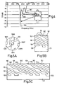
- this is done by forming the helical elements 10A, 10B, 10C and 10D such that their outermost edges are meandered with respect to their respective helical paths, as shown in Figures 3A to 3C.
- the outwardly directed edge 10AO, 10BO, 10CO, 10DO of each helical element 10A to 10D deviates from the helical path in a sinusoidal manner along the whole of its length.
- the inner edges of the elements 10A to 10D are, in this embodiment, strictly helical and parallel to each other on opposite sides of the respective channel 11AB, 11CD.
- the sinusoidal paths of the outermost edges of the elements of each group are also parallel. This is because at any given point along the elements 10A, 10B or 10C, 10D of a group, the deviations of the respective outermost edges are in the same direction. The deviations also have the same pitch and the same amplitude.
- the effect of the meandering of the outermost edges of the elements 10A, 10B, 10C, 10D is to shift the natural frequency of the common-current mode down to a frequency which depends on the amplitude of the meandering.
- the common-current resonant mode which produces resonance 30C ( Figure 2) has its highest current density at the outermost edges 10AO to 10DO, and altering the amplitude of the meandering tunes the frequency of the resonance 30C at a faster rate than the frequencies of the individual elements (i.e. the resonances 30A, 30B in Figure 2).
- This variation in the length of the outermost edges of the elements 10A to 10D can be used to shift the third resonance 30C closer to the resonances 30A and 30B, as shown in Figure 4, to produce an advantageous insertion loss characteristic covering a band of frequencies.
- the antenna has an operating band coincident with the IMT-2000 3-G receive band of 2110 to 2170MHz, and a fractional bandwidth approaching 3% at -9dB has been achieved.
- each group of antenna elements may comprise three elongate elements 10E, 10F, 10G, 10H, 10I and 10J, as shown in Figures 5A to 5C, which are views corresponding to the views of Figures 3A to 3C in respective of the first embodiment.
- each element has a corresponding radial portion 10ER to 10JR connecting to the feeder structure, and each element is terminated at the rim 20U of the sleeve 20.
- the elements within each group 10E, 10F, 10G; 10H, 10I, 10J are separated from each other by half wave channels 11EF, 11FG; 11HI, 11IJ which, as in the first embodiment, extends from the distal face 12D of the core into the sleeve 20, as shown.
- the elements in each group are of different average widths, each element within each group having an element of a corresponding width in the other group, elements of equal average width being diametrically opposed across the core on opposite sides of the core axis.
- the narrowest elements are elements 10ER and 10HR.
- the next wider elements are those labelled 10GR and 10JR, and the widest elements are the elements in the middle of their respective groups, elements 10FR and 10IR.
- the three-element structure offers shared current modes associated with currents common to respective pairs of elements (producing magnetic fields 30G and 30H) and currents common to all three elements (producing a magnetic field appearing in Figure 6 as field 30I).
- this antenna offers six fundamental balanced mode resonances which, with appropriate adjustment of the widths of the elements 10E to 10J and meandering of element edges, can be brought together as a collection of coupled resonances, as shown in Figure 7.
- the antenna is configured to produce resonances forming an operating band corresponding to the GSM1800 band extending from 1710 to 1880 MHz.
- the outer elements of each group have their outermost edges meandered.
- the inner edges of the outer elements 10E, 10G; 10H, 10J may also be meandered, but to a lesser amplitude than the meandering of the outer edges.
- the edges of the inner elements 10F, 10I are helical in this case.
- the bandwidth of an antenna can be increased using the techniques described above, some applications may require still greater bandwidth.
- the 3-G receive and transmit bands as specified by the IMT-2000 frequency allocation are neighbouring bands which, depending on the performance required, may not be covered by a single antenna. Since dielectrically-loaded antennas as described above are very small at the frequencies of the 3-G bands, it is possible to mount a plurality of such antennas in a single mobile telephone handset.
- the antennas described above are balanced mode antennas which, in use, are isolated from the handset ground. It is possible to employ a first antenna covering the transmit band and a second antenna covering the receive band, each having a filtering response (as shown in the graphs included in the drawings of the present application) to reject the other band. This allows the expensive diplexer filter of the conventional approach in this situation (i.e. a broadband antenna and a diplexer) to be dispensed with.
Claims (19)
- Antenne à charge diélectrique destinée à fonctionner à des fréquences supérieures à 200 MHz, comprenant un noyau (12) isolant de l'électricité, formé d'un matériau plein ayant une constante diélectrique relative supérieure à 5, une connexion d'alimentation, une structure à éléments d'antenne disposée à la surface externe du noyau ou adjacente à cette surface, le matériau du noyau occupant la plus grande partie du volume délimité par la surface externe du noyau, dans laquelle la structure à éléments d'antenne comporte une paire de groupes latéralement opposés (10A, 10B-10C, 10D; 10E; 10F, 10G-10H, 10I, 10J) d'éléments allongés conducteurs, chaque groupe comprenant des premier et second éléments allongés pratiquement de même étendue qui ont des longueurs électriques différentes à une fréquence comprise dans la bande des fréquences de fonctionnement de l'antenne et sont couplés mutuellement à deux premières extrémités respectives à un emplacement de la région de la connexion d'alimentation et à des secondes extrémités respectives à un emplacement distant de la connexion d'alimentation, la structure à éléments d'antenne comprenant en outre un conducteur de liaison (20) qui relie les secondes extrémités des premiers et seconds éléments allongés d'un groupe aux secondes extrémités des premiers et seconds éléments de l'autre groupe, de sorte que les premiers éléments (10A, 10C ; 10E, 10H) des deux groupes font partie d'un premier trajet conducteur en boucle, et les seconds éléments (10B, 10D ; 10F, 10I; 10G, 10J) des deux groupes font partie d'un second trajet conducteur en boucle, d'une manière telle que les trajets ont des fréquences respectives de résonance différentes dans ladite bande et s'étendent chacun de la connexion d'alimentation au conducteur de liaison, puis reviennent à la connexion d'alimentation, l'un au moins des éléments allongés d'antenne comprenant une bande conductrice placée à la surface externe du noyau, la bande ayant des bords opposés de longueurs différentes.
- Antenne selon la revendication 1, dans laquelle la bande ou chaque bande conductrice a des bords opposés de longueurs différentes parce que les bords opposés ne sont pas parallèles.
- Antenne selon la revendication 1 ou 2, dans laquelle le bord de la bande qui est le plus éloigné de l'autre élément ou des autres éléments allongés de son groupe est plus long que le bord qui est plus proche de l'autre élément ou des autres éléments allongés du groupe.
- Antenne selon la revendication 1 ou 2, dans laquelle l'un au moins des bords de la bande ou de chaque bande conductrice a une forme sinueuse.
- Antenne selon l'une quelconque des revendications précédentes, dans laquelle les premier et second éléments allongés de chaque groupe ont un bord qui est un bord le plus externe du groupe, et les deux bords les plus externes sont plus longs que les bords internes de ces éléments du groupe.
- Antenne selon la revendication 5, dans laquelle les bords les plus externes de chaque groupe sont pratiquement parallèles l'un à l'autre.
- Antenne selon l'une quelconque des revendications 3 à 6, dans laquelle les bords relativement longs sont chacun sinueux sur la plus grande partie de leur longueur.
- Antenne selon l'une quelconque des revendications précédentes, dans laquelle chaque groupe d'éléments allongés d'antenne possède deux éléments adjacents mutuellement.
- Antenne selon la revendication 8, dans laquelle les éléments allongés de chaque paire ont des longueurs électriques différentes et délimitent entre eux un canal à côtés parallèles, chaque élément ayant un bord externe sinueux.
- Antenne selon l'une quelconque des revendications précédentes, dans laquelle chaque groupe d'éléments allongés d'antenne a trois éléments allongés disposés côte à côte.
- Antenne selon la revendication 10, dans laquelle les bords les plus à l'extérieur des éléments externes de chaque groupe sont sinueux et l'élément interne a des côtés parallèles.
- Antenne selon la revendication 10, dans laquelle l'un au moins des éléments externes de chaque groupe a un bord externe sinueux et un bord interne sinueux, l'amplitude de la sinuosité du bord externe étant plus grande que celle du bord interne.
- Antenne selon l'une quelconque des revendications précédentes, dans laquelle les éléments allongés d'antenne s'étendent chacun depuis la connexion d'alimentation jusqu'au conducteur de liaison, et ont chacun une longueur électrique de l'ordre d'une demi-longueur d'onde à une fréquence comprise dans la bande de fréquences de fonctionnement de l'antenne.
- Antenne selon la revendication 13, dans laquelle le noyau (12) est cylindrique et la connexion d'alimentation comporte une terminaison d'un organe d'alimentation sur une face d'extrémité (12D) du noyau, dans laquelle la plus grande partie de chacun des éléments allongés d'antenne (10A-10J) comprend un conducteur en hélice qui effectue un demi-tour autour du noyau en étant centré sur l'axe du noyau, et dans laquelle le conducteur de liaison comporte un conducteur annulaire (20) placé autour du noyau et centré sur l'axe.
- Antenne selon la revendication 14, comprenant une structure d'organe d'alimentation axiale (16, 17, 18) qui s'étend à travers le noyau (12) de la connexion d'alimentation à une première face d'extrémité (12D) du noyau à une seconde face d'extrémité (12P) du noyau, et dans laquelle le conducteur de liaison comporte un manchon conducteur (20) qui connecte les secondes extrémités des éléments allongés à la structure à organe d'alimentation à une position distante de la connexion d'alimentation.
- Antenne selon l'une quelconque des revendications précédentes ayant une largeur de bande fractionnaire d'au moins 3 % pour des pertes d'insertion de -6 dB.
- Antenne selon la revendication 1, dans laquelle le noyau (12) a des surfaces d'extrémité et des surfaces latérales, et un axe de symétrie passant par les surfaces d'extrémité, dans laquelle les premiers et seconds éléments allongés de chaque groupe (10A, 10B-10C, 10D ; 10E, 10F, 10G-10H, 10I, 10J) sont disposés côte à côte aux surfaces latérales du noyau ou près de ces surfaces, et dans laquelle l'un au moins des éléments allongés d'antenne placés sur les surfaces latérales ou adjacents à ces surfaces comporte une bande conductrice ayant des bords opposés non parallèles tels que les bords opposés de la bande ont des longueurs différentes.
- Antenne selon la revendication 17, dans laquelle la connexion d'alimentation est disposée sur l'une (12D) des surfaces d'extrémité du noyau et les éléments allongés du groupe sont connectés à la connexion d'alimentation par plusieurs éléments de connexion (10AR-10DR ; 10ER, 10JR) placés à la surface d'extrémité ou adjacents à cette surface.
- Antenne selon la revendication 17 ou 18, dans laquelle la bande a des bords non parallèles sur la plus grande partie au moins de sa longueur à la surface ou aux surfaces respectives du noyau (12).
Applications Claiming Priority (3)
| Application Number | Priority Date | Filing Date | Title |
|---|---|---|---|
| GB0307251A GB2399948B (en) | 2003-03-28 | 2003-03-28 | A dielectrically-loaded antenna |
| GB0307251 | 2003-03-28 | ||
| PCT/GB2004/001109 WO2004086561A1 (fr) | 2003-03-28 | 2004-03-16 | Antenne dielectriquement chargee |
Publications (2)
| Publication Number | Publication Date |
|---|---|
| EP1609213A1 EP1609213A1 (fr) | 2005-12-28 |
| EP1609213B1 true EP1609213B1 (fr) | 2007-11-14 |
Family
ID=9955774
Family Applications (1)
| Application Number | Title | Priority Date | Filing Date |
|---|---|---|---|
| EP04720919A Expired - Lifetime EP1609213B1 (fr) | 2003-03-28 | 2004-03-16 | Antenne dielectriquement chargee |
Country Status (15)
| Country | Link |
|---|---|
| US (1) | US6914580B2 (fr) |
| EP (1) | EP1609213B1 (fr) |
| JP (1) | JP4489759B2 (fr) |
| KR (1) | KR101058130B1 (fr) |
| CN (1) | CN1768450B (fr) |
| AT (1) | ATE378702T1 (fr) |
| AU (1) | AU2004223229B2 (fr) |
| BR (1) | BRPI0408751A (fr) |
| CA (1) | CA2521493A1 (fr) |
| DE (1) | DE602004010085T2 (fr) |
| GB (1) | GB2399948B (fr) |
| MX (1) | MXPA05010441A (fr) |
| RU (1) | RU2339131C2 (fr) |
| TW (1) | TWI285980B (fr) |
| WO (1) | WO2004086561A1 (fr) |
Families Citing this family (45)
| Publication number | Priority date | Publication date | Assignee | Title |
|---|---|---|---|---|
| US5914613A (en) | 1996-08-08 | 1999-06-22 | Cascade Microtech, Inc. | Membrane probing system with local contact scrub |
| US6256882B1 (en) | 1998-07-14 | 2001-07-10 | Cascade Microtech, Inc. | Membrane probing system |
| US6914423B2 (en) | 2000-09-05 | 2005-07-05 | Cascade Microtech, Inc. | Probe station |
| US6965226B2 (en) | 2000-09-05 | 2005-11-15 | Cascade Microtech, Inc. | Chuck for holding a device under test |
| DE20114544U1 (de) | 2000-12-04 | 2002-02-21 | Cascade Microtech Inc | Wafersonde |
| WO2003052435A1 (fr) | 2001-08-21 | 2003-06-26 | Cascade Microtech, Inc. | Systeme de detection a membrane |
| GB0505771D0 (en) * | 2005-03-21 | 2005-04-27 | Sarantel Ltd | Dielectrically-loaded antenna |
| US7492172B2 (en) | 2003-05-23 | 2009-02-17 | Cascade Microtech, Inc. | Chuck for holding a device under test |
| US7057404B2 (en) | 2003-05-23 | 2006-06-06 | Sharp Laboratories Of America, Inc. | Shielded probe for testing a device under test |
| US7250626B2 (en) | 2003-10-22 | 2007-07-31 | Cascade Microtech, Inc. | Probe testing structure |
| DE202004021093U1 (de) | 2003-12-24 | 2006-09-28 | Cascade Microtech, Inc., Beaverton | Aktiver Halbleiterscheibenmessfühler |
| US7187188B2 (en) | 2003-12-24 | 2007-03-06 | Cascade Microtech, Inc. | Chuck with integrated wafer support |
| US7420381B2 (en) | 2004-09-13 | 2008-09-02 | Cascade Microtech, Inc. | Double sided probing structures |
| US7002530B1 (en) * | 2004-09-30 | 2006-02-21 | Etop Technology Co., Ltd. | Antenna |
| US7656172B2 (en) | 2005-01-31 | 2010-02-02 | Cascade Microtech, Inc. | System for testing semiconductors |
| US7535247B2 (en) | 2005-01-31 | 2009-05-19 | Cascade Microtech, Inc. | Interface for testing semiconductors |
| GB2437998B (en) * | 2006-05-12 | 2009-11-11 | Sarantel Ltd | An antenna system |
| US7403028B2 (en) | 2006-06-12 | 2008-07-22 | Cascade Microtech, Inc. | Test structure and probe for differential signals |
| US7723999B2 (en) | 2006-06-12 | 2010-05-25 | Cascade Microtech, Inc. | Calibration structures for differential signal probing |
| US7764072B2 (en) | 2006-06-12 | 2010-07-27 | Cascade Microtech, Inc. | Differential signal probing system |
| GB2441566A (en) * | 2006-09-06 | 2008-03-12 | Sarantel Ltd | An antenna and its feed structure |
| GB2442998B (en) * | 2006-10-20 | 2010-01-06 | Sarantel Ltd | A dielectrically-loaded antenna |
| US7394435B1 (en) * | 2006-12-08 | 2008-07-01 | Wide Sky Technology, Inc. | Slot antenna |
| GB2444750B (en) | 2006-12-14 | 2010-04-21 | Sarantel Ltd | An antenna arrangement |
| GB2444749B (en) * | 2006-12-14 | 2009-11-18 | Sarantel Ltd | A radio communication system |
| GB2449837B (en) * | 2006-12-20 | 2011-09-07 | Sarantel Ltd | A dielectrically-loaded antenna |
| GB0700276D0 (en) * | 2007-01-08 | 2007-02-14 | Sarantel Ltd | A dielectrically-loaded antenna |
| US7876114B2 (en) | 2007-08-08 | 2011-01-25 | Cascade Microtech, Inc. | Differential waveguide probe |
| US8089421B2 (en) | 2008-01-08 | 2012-01-03 | Sarantel Limited | Dielectrically loaded antenna |
| US8799861B2 (en) * | 2008-01-30 | 2014-08-05 | Intuit Inc. | Performance-testing a system with functional-test software and a transformation-accelerator |
| GB0815306D0 (en) | 2008-08-21 | 2008-09-24 | Sarantel Ltd | An antenna and a method of manufacturing an antenna |
| US7888957B2 (en) | 2008-10-06 | 2011-02-15 | Cascade Microtech, Inc. | Probing apparatus with impedance optimized interface |
| US8410806B2 (en) | 2008-11-21 | 2013-04-02 | Cascade Microtech, Inc. | Replaceable coupon for a probing apparatus |
| US8319503B2 (en) | 2008-11-24 | 2012-11-27 | Cascade Microtech, Inc. | Test apparatus for measuring a characteristic of a device under test |
| GB0904307D0 (en) * | 2009-03-12 | 2009-04-22 | Sarantel Ltd | A dielectrically-loaded antenna |
| WO2010103264A1 (fr) * | 2009-03-12 | 2010-09-16 | Sarantel Limited | Antenne à charge diélectrique |
| US8106846B2 (en) * | 2009-05-01 | 2012-01-31 | Applied Wireless Identifications Group, Inc. | Compact circular polarized antenna |
| US8456375B2 (en) | 2009-05-05 | 2013-06-04 | Sarantel Limited | Multifilar antenna |
| US8618998B2 (en) | 2009-07-21 | 2013-12-31 | Applied Wireless Identifications Group, Inc. | Compact circular polarized antenna with cavity for additional devices |
| GB2473676B (en) * | 2009-09-22 | 2012-10-24 | Sarantel Ltd | An antenna assembly with an integrated coaxial connector |
| US8599101B2 (en) | 2010-01-27 | 2013-12-03 | Sarantel Limited | Dielectrically loaded antenna and radio communication apparatus |
| GB2477290B (en) | 2010-01-27 | 2014-04-09 | Harris Corp | A dielectrically loaded antenna and radio communication apparatus |
| GB2477289B (en) | 2010-01-27 | 2014-08-13 | Harris Corp | A radio communication apparatus having improved resistance to common mode noise |
| WO2012142764A1 (fr) * | 2011-04-21 | 2012-10-26 | Tandy Radio Shack Limited | Système d'antenne cadre efficace et procédé associé |
| CN109742519B (zh) * | 2018-12-17 | 2020-08-21 | 深圳市华信天线技术有限公司 | 一种宽带螺旋组合多网通天线 |
Family Cites Families (21)
| Publication number | Priority date | Publication date | Assignee | Title |
|---|---|---|---|---|
| US4008479A (en) * | 1975-11-03 | 1977-02-15 | Chu Associates, Inc. | Dual-frequency circularly polarized spiral antenna for satellite navigation |
| US4114164A (en) * | 1976-12-17 | 1978-09-12 | Transco Products, Inc. | Broadband spiral antenna |
| FR2624656B1 (fr) * | 1987-12-10 | 1990-05-18 | Centre Nat Etd Spatiales | Antenne de type helice et son procede de realisation |
| US5198831A (en) * | 1990-09-26 | 1993-03-30 | 501 Pronav International, Inc. | Personal positioning satellite navigator with printed quadrifilar helical antenna |
| US5346300A (en) * | 1991-07-05 | 1994-09-13 | Sharp Kabushiki Kaisha | Back fire helical antenna |
| FR2711277B1 (fr) | 1993-10-14 | 1995-11-10 | Alcatel Mobile Comm France | Antenne du type pour dispositif radio portable, procédé de fabrication d'une telle antenne et dispositif radio portable comportant une telle antenne. |
| GB9417450D0 (en) * | 1994-08-25 | 1994-10-19 | Symmetricom Inc | An antenna |
| GB9601250D0 (en) * | 1996-01-23 | 1996-03-27 | Symmetricom Inc | An antenna |
| GB9603914D0 (en) * | 1996-02-23 | 1996-04-24 | Symmetricom Inc | An antenna |
| FR2746547B1 (fr) | 1996-03-19 | 1998-06-19 | France Telecom | Antenne helice a alimentation large bande integree, et procedes de fabrication correspondants |
| GB9606593D0 (en) * | 1996-03-29 | 1996-06-05 | Symmetricom Inc | An antenna system |
| US6184845B1 (en) * | 1996-11-27 | 2001-02-06 | Symmetricom, Inc. | Dielectric-loaded antenna |
| SE514530C2 (sv) | 1998-05-18 | 2001-03-12 | Allgon Ab | Antennanordning omfattande kapacitivt kopplade radiotorelement och en handburen radiokommunikationsanordning för en sådan antennanordning |
| JP2000036707A (ja) * | 1998-07-17 | 2000-02-02 | Takayuki Ishizone | 装荷4線ヘリカルアンテナ |
| US6088000A (en) * | 1999-03-05 | 2000-07-11 | Garmin Corporation | Quadrifilar tapered slot antenna |
| GB9912441D0 (en) * | 1999-05-27 | 1999-07-28 | Symmetricon Inc | An antenna |
| US6407720B1 (en) * | 1999-07-19 | 2002-06-18 | The United States Of America As Represented By The Secretary Of The Navy | Capacitively loaded quadrifilar helix antenna |
| US6429830B2 (en) * | 2000-05-18 | 2002-08-06 | Mitsumi Electric Co., Ltd. | Helical antenna, antenna unit, composite antenna |
| US6288686B1 (en) * | 2000-06-23 | 2001-09-11 | The United States Of America As Represented By The Secretary Of The Navy | Tapered direct fed quadrifilar helix antenna |
| FR2814285A1 (fr) * | 2000-09-15 | 2002-03-22 | France Telecom | Antenne helicoidale a pas variable, et procede correspondant |
| FR2814286B1 (fr) * | 2000-09-15 | 2004-05-28 | France Telecom | Antenne helice a brins de largeur variable |
-
2003
- 2003-03-28 GB GB0307251A patent/GB2399948B/en not_active Expired - Fee Related
- 2003-06-09 US US10/457,717 patent/US6914580B2/en not_active Expired - Fee Related
-
2004
- 2004-03-16 DE DE602004010085T patent/DE602004010085T2/de not_active Expired - Lifetime
- 2004-03-16 CA CA002521493A patent/CA2521493A1/fr not_active Abandoned
- 2004-03-16 RU RU2005129344/09A patent/RU2339131C2/ru not_active IP Right Cessation
- 2004-03-16 KR KR1020057018375A patent/KR101058130B1/ko not_active IP Right Cessation
- 2004-03-16 EP EP04720919A patent/EP1609213B1/fr not_active Expired - Lifetime
- 2004-03-16 AU AU2004223229A patent/AU2004223229B2/en not_active Ceased
- 2004-03-16 CN CN200480008651XA patent/CN1768450B/zh not_active Expired - Fee Related
- 2004-03-16 AT AT04720919T patent/ATE378702T1/de not_active IP Right Cessation
- 2004-03-16 JP JP2006505967A patent/JP4489759B2/ja not_active Expired - Fee Related
- 2004-03-16 MX MXPA05010441A patent/MXPA05010441A/es active IP Right Grant
- 2004-03-16 BR BRPI0408751-8A patent/BRPI0408751A/pt not_active IP Right Cessation
- 2004-03-16 WO PCT/GB2004/001109 patent/WO2004086561A1/fr active IP Right Grant
- 2004-03-22 TW TW093107605A patent/TWI285980B/zh not_active IP Right Cessation
Also Published As
| Publication number | Publication date |
|---|---|
| CN1768450A (zh) | 2006-05-03 |
| JP2006521733A (ja) | 2006-09-21 |
| ATE378702T1 (de) | 2007-11-15 |
| GB0307251D0 (en) | 2003-04-30 |
| GB2399948B (en) | 2006-06-21 |
| DE602004010085D1 (de) | 2007-12-27 |
| KR20060031797A (ko) | 2006-04-13 |
| TW200505097A (en) | 2005-02-01 |
| GB2399948A (en) | 2004-09-29 |
| AU2004223229A1 (en) | 2004-10-07 |
| CA2521493A1 (fr) | 2004-10-07 |
| EP1609213A1 (fr) | 2005-12-28 |
| TWI285980B (en) | 2007-08-21 |
| US6914580B2 (en) | 2005-07-05 |
| US20040189541A1 (en) | 2004-09-30 |
| KR101058130B1 (ko) | 2011-08-24 |
| WO2004086561A1 (fr) | 2004-10-07 |
| RU2339131C2 (ru) | 2008-11-20 |
| RU2005129344A (ru) | 2006-03-27 |
| DE602004010085T2 (de) | 2008-10-30 |
| MXPA05010441A (es) | 2005-12-05 |
| AU2004223229B2 (en) | 2008-06-19 |
| CN1768450B (zh) | 2012-02-08 |
| BRPI0408751A (pt) | 2006-03-28 |
| JP4489759B2 (ja) | 2010-06-23 |
Similar Documents
| Publication | Publication Date | Title |
|---|---|---|
| EP1609213B1 (fr) | Antenne dielectriquement chargee | |
| US7372427B2 (en) | Dielectrically-loaded antenna | |
| EP1196963B1 (fr) | Antenne cadre presentant quatre frequences de resonance | |
| US6184845B1 (en) | Dielectric-loaded antenna | |
| EP0916167B1 (fr) | Antenne helicoidale a segments et a bande double | |
| US7903044B2 (en) | Dielectrically-loaded antenna | |
| WO1997041695A2 (fr) | Antenne helicoidale a segments multiples couples | |
| WO1998005087A9 (fr) | Antenne helicoidale a segments et a bande double | |
| TWI508369B (zh) | 介電負載天線(一) | |
| WO2012160353A1 (fr) | Antenne à chargement diélectrique | |
| US8089421B2 (en) | Dielectrically loaded antenna | |
| EP0970540B1 (fr) | Antenne et reseau d'alimentation d'antenne | |
| MXPA99004946A (en) | A dielectric-loaded antenna |
Legal Events
| Date | Code | Title | Description |
|---|---|---|---|
| PUAI | Public reference made under article 153(3) epc to a published international application that has entered the european phase |
Free format text: ORIGINAL CODE: 0009012 |
|
| 17P | Request for examination filed |
Effective date: 20051010 |
|
| AK | Designated contracting states |
Kind code of ref document: A1 Designated state(s): AT BE BG CH CY CZ DE DK EE ES FI FR GB GR HU IE IT LI LU MC NL PL PT RO SE SI SK TR |
|
| AX | Request for extension of the european patent |
Extension state: AL LT LV MK |
|
| DAX | Request for extension of the european patent (deleted) | ||
| RBV | Designated contracting states (corrected) |
Designated state(s): AT BE BG CH CY CZ DE DK EE ES FI FR GB GR HU IE IT LI LU MC NL PL PT RO SE SI SK TR |
|
| GRAP | Despatch of communication of intention to grant a patent |
Free format text: ORIGINAL CODE: EPIDOSNIGR1 |
|
| RBV | Designated contracting states (corrected) |
Designated state(s): AT BE BG CH CY CZ DE DK EE ES FI FR GR HU IE IT LI LU MC NL PL PT RO SE SI SK TR |
|
| GRAS | Grant fee paid |
Free format text: ORIGINAL CODE: EPIDOSNIGR3 |
|
| GRAA | (expected) grant |
Free format text: ORIGINAL CODE: 0009210 |
|
| AK | Designated contracting states |
Kind code of ref document: B1 Designated state(s): AT BE BG CH CY CZ DE DK EE ES FI FR GR HU IE IT LI LU MC NL PL PT RO SE SI SK TR |
|
| REG | Reference to a national code |
Ref country code: CH Ref legal event code: EP |
|
| REG | Reference to a national code |
Ref country code: IE Ref legal event code: FG4D |
|
| REF | Corresponds to: |
Ref document number: 602004010085 Country of ref document: DE Date of ref document: 20071227 Kind code of ref document: P |
|
| REG | Reference to a national code |
Ref country code: SE Ref legal event code: TRGR |
|
| PG25 | Lapsed in a contracting state [announced via postgrant information from national office to epo] |
Ref country code: LI Free format text: LAPSE BECAUSE OF FAILURE TO SUBMIT A TRANSLATION OF THE DESCRIPTION OR TO PAY THE FEE WITHIN THE PRESCRIBED TIME-LIMIT Effective date: 20071114 Ref country code: ES Free format text: LAPSE BECAUSE OF FAILURE TO SUBMIT A TRANSLATION OF THE DESCRIPTION OR TO PAY THE FEE WITHIN THE PRESCRIBED TIME-LIMIT Effective date: 20080225 Ref country code: CH Free format text: LAPSE BECAUSE OF FAILURE TO SUBMIT A TRANSLATION OF THE DESCRIPTION OR TO PAY THE FEE WITHIN THE PRESCRIBED TIME-LIMIT Effective date: 20071114 Ref country code: NL Free format text: LAPSE BECAUSE OF FAILURE TO SUBMIT A TRANSLATION OF THE DESCRIPTION OR TO PAY THE FEE WITHIN THE PRESCRIBED TIME-LIMIT Effective date: 20071114 |
|
| NLV1 | Nl: lapsed or annulled due to failure to fulfill the requirements of art. 29p and 29m of the patents act | ||
| PG25 | Lapsed in a contracting state [announced via postgrant information from national office to epo] |
Ref country code: SI Free format text: LAPSE BECAUSE OF FAILURE TO SUBMIT A TRANSLATION OF THE DESCRIPTION OR TO PAY THE FEE WITHIN THE PRESCRIBED TIME-LIMIT Effective date: 20071114 Ref country code: BG Free format text: LAPSE BECAUSE OF FAILURE TO SUBMIT A TRANSLATION OF THE DESCRIPTION OR TO PAY THE FEE WITHIN THE PRESCRIBED TIME-LIMIT Effective date: 20080214 Ref country code: PL Free format text: LAPSE BECAUSE OF FAILURE TO SUBMIT A TRANSLATION OF THE DESCRIPTION OR TO PAY THE FEE WITHIN THE PRESCRIBED TIME-LIMIT Effective date: 20071114 |
|
| REG | Reference to a national code |
Ref country code: CH Ref legal event code: PL |
|
| PG25 | Lapsed in a contracting state [announced via postgrant information from national office to epo] |
Ref country code: AT Free format text: LAPSE BECAUSE OF FAILURE TO SUBMIT A TRANSLATION OF THE DESCRIPTION OR TO PAY THE FEE WITHIN THE PRESCRIBED TIME-LIMIT Effective date: 20071114 |
|
| ET | Fr: translation filed | ||
| PG25 | Lapsed in a contracting state [announced via postgrant information from national office to epo] |
Ref country code: DK Free format text: LAPSE BECAUSE OF FAILURE TO SUBMIT A TRANSLATION OF THE DESCRIPTION OR TO PAY THE FEE WITHIN THE PRESCRIBED TIME-LIMIT Effective date: 20071114 Ref country code: CZ Free format text: LAPSE BECAUSE OF FAILURE TO SUBMIT A TRANSLATION OF THE DESCRIPTION OR TO PAY THE FEE WITHIN THE PRESCRIBED TIME-LIMIT Effective date: 20071114 |
|
| PG25 | Lapsed in a contracting state [announced via postgrant information from national office to epo] |
Ref country code: SK Free format text: LAPSE BECAUSE OF FAILURE TO SUBMIT A TRANSLATION OF THE DESCRIPTION OR TO PAY THE FEE WITHIN THE PRESCRIBED TIME-LIMIT Effective date: 20071114 Ref country code: RO Free format text: LAPSE BECAUSE OF FAILURE TO SUBMIT A TRANSLATION OF THE DESCRIPTION OR TO PAY THE FEE WITHIN THE PRESCRIBED TIME-LIMIT Effective date: 20071114 Ref country code: BE Free format text: LAPSE BECAUSE OF FAILURE TO SUBMIT A TRANSLATION OF THE DESCRIPTION OR TO PAY THE FEE WITHIN THE PRESCRIBED TIME-LIMIT Effective date: 20071114 |
|
| PLBE | No opposition filed within time limit |
Free format text: ORIGINAL CODE: 0009261 |
|
| STAA | Information on the status of an ep patent application or granted ep patent |
Free format text: STATUS: NO OPPOSITION FILED WITHIN TIME LIMIT |
|
| PG25 | Lapsed in a contracting state [announced via postgrant information from national office to epo] |
Ref country code: PT Free format text: LAPSE BECAUSE OF FAILURE TO SUBMIT A TRANSLATION OF THE DESCRIPTION OR TO PAY THE FEE WITHIN THE PRESCRIBED TIME-LIMIT Effective date: 20080414 |
|
| 26N | No opposition filed |
Effective date: 20080815 |
|
| PG25 | Lapsed in a contracting state [announced via postgrant information from national office to epo] |
Ref country code: MC Free format text: LAPSE BECAUSE OF NON-PAYMENT OF DUE FEES Effective date: 20080331 |
|
| PG25 | Lapsed in a contracting state [announced via postgrant information from national office to epo] |
Ref country code: EE Free format text: LAPSE BECAUSE OF FAILURE TO SUBMIT A TRANSLATION OF THE DESCRIPTION OR TO PAY THE FEE WITHIN THE PRESCRIBED TIME-LIMIT Effective date: 20071114 Ref country code: GR Free format text: LAPSE BECAUSE OF FAILURE TO SUBMIT A TRANSLATION OF THE DESCRIPTION OR TO PAY THE FEE WITHIN THE PRESCRIBED TIME-LIMIT Effective date: 20080215 Ref country code: IE Free format text: LAPSE BECAUSE OF NON-PAYMENT OF DUE FEES Effective date: 20080317 |
|
| PGFP | Annual fee paid to national office [announced via postgrant information from national office to epo] |
Ref country code: FI Payment date: 20090224 Year of fee payment: 6 |
|
| PG25 | Lapsed in a contracting state [announced via postgrant information from national office to epo] |
Ref country code: CY Free format text: LAPSE BECAUSE OF FAILURE TO SUBMIT A TRANSLATION OF THE DESCRIPTION OR TO PAY THE FEE WITHIN THE PRESCRIBED TIME-LIMIT Effective date: 20071114 |
|
| PGFP | Annual fee paid to national office [announced via postgrant information from national office to epo] |
Ref country code: SE Payment date: 20090317 Year of fee payment: 6 |
|
| PGFP | Annual fee paid to national office [announced via postgrant information from national office to epo] |
Ref country code: FR Payment date: 20100316 Year of fee payment: 7 |
|
| PG25 | Lapsed in a contracting state [announced via postgrant information from national office to epo] |
Ref country code: HU Free format text: LAPSE BECAUSE OF FAILURE TO SUBMIT A TRANSLATION OF THE DESCRIPTION OR TO PAY THE FEE WITHIN THE PRESCRIBED TIME-LIMIT Effective date: 20080515 Ref country code: LU Free format text: LAPSE BECAUSE OF NON-PAYMENT OF DUE FEES Effective date: 20080316 |
|
| PG25 | Lapsed in a contracting state [announced via postgrant information from national office to epo] |
Ref country code: TR Free format text: LAPSE BECAUSE OF FAILURE TO SUBMIT A TRANSLATION OF THE DESCRIPTION OR TO PAY THE FEE WITHIN THE PRESCRIBED TIME-LIMIT Effective date: 20071114 |
|
| PGFP | Annual fee paid to national office [announced via postgrant information from national office to epo] |
Ref country code: DE Payment date: 20100419 Year of fee payment: 7 |
|
| EUG | Se: european patent has lapsed | ||
| PG25 | Lapsed in a contracting state [announced via postgrant information from national office to epo] |
Ref country code: FI Free format text: LAPSE BECAUSE OF NON-PAYMENT OF DUE FEES Effective date: 20100316 |
|
| PG25 | Lapsed in a contracting state [announced via postgrant information from national office to epo] |
Ref country code: IT Free format text: LAPSE BECAUSE OF NON-PAYMENT OF DUE FEES Effective date: 20080331 |
|
| REG | Reference to a national code |
Ref country code: FR Ref legal event code: ST Effective date: 20111130 |
|
| PG25 | Lapsed in a contracting state [announced via postgrant information from national office to epo] |
Ref country code: DE Free format text: LAPSE BECAUSE OF NON-PAYMENT OF DUE FEES Effective date: 20111001 Ref country code: FR Free format text: LAPSE BECAUSE OF NON-PAYMENT OF DUE FEES Effective date: 20110331 |
|
| REG | Reference to a national code |
Ref country code: DE Ref legal event code: R119 Ref document number: 602004010085 Country of ref document: DE Effective date: 20111001 |
|
| PG25 | Lapsed in a contracting state [announced via postgrant information from national office to epo] |
Ref country code: SE Free format text: LAPSE BECAUSE OF NON-PAYMENT OF DUE FEES Effective date: 20100317 |