EP1607947A1 - Method for controlling trial write onto optical recording medium - Google Patents
Method for controlling trial write onto optical recording medium Download PDFInfo
- Publication number
- EP1607947A1 EP1607947A1 EP04722675A EP04722675A EP1607947A1 EP 1607947 A1 EP1607947 A1 EP 1607947A1 EP 04722675 A EP04722675 A EP 04722675A EP 04722675 A EP04722675 A EP 04722675A EP 1607947 A1 EP1607947 A1 EP 1607947A1
- Authority
- EP
- European Patent Office
- Prior art keywords
- medium
- record
- information
- circumference side
- write trial
- Prior art date
- Legal status (The legal status is an assumption and is not a legal conclusion. Google has not performed a legal analysis and makes no representation as to the accuracy of the status listed.)
- Granted
Links
Images





Classifications
-
- G—PHYSICS
- G11—INFORMATION STORAGE
- G11B—INFORMATION STORAGE BASED ON RELATIVE MOVEMENT BETWEEN RECORD CARRIER AND TRANSDUCER
- G11B7/00—Recording or reproducing by optical means, e.g. recording using a thermal beam of optical radiation by modifying optical properties or the physical structure, reproducing using an optical beam at lower power by sensing optical properties; Record carriers therefor
- G11B7/12—Heads, e.g. forming of the optical beam spot or modulation of the optical beam
- G11B7/125—Optical beam sources therefor, e.g. laser control circuitry specially adapted for optical storage devices; Modulators, e.g. means for controlling the size or intensity of optical spots or optical traces
- G11B7/126—Circuits, methods or arrangements for laser control or stabilisation
- G11B7/1267—Power calibration
-
- G—PHYSICS
- G11—INFORMATION STORAGE
- G11B—INFORMATION STORAGE BASED ON RELATIVE MOVEMENT BETWEEN RECORD CARRIER AND TRANSDUCER
- G11B7/00—Recording or reproducing by optical means, e.g. recording using a thermal beam of optical radiation by modifying optical properties or the physical structure, reproducing using an optical beam at lower power by sensing optical properties; Record carriers therefor
- G11B7/007—Arrangement of the information on the record carrier, e.g. form of tracks, actual track shape, e.g. wobbled, or cross-section, e.g. v-shaped; Sequential information structures, e.g. sectoring or header formats within a track
- G11B7/00736—Auxiliary data, e.g. lead-in, lead-out, Power Calibration Area [PCA], Burst Cutting Area [BCA], control information
-
- G—PHYSICS
- G11—INFORMATION STORAGE
- G11B—INFORMATION STORAGE BASED ON RELATIVE MOVEMENT BETWEEN RECORD CARRIER AND TRANSDUCER
- G11B7/00—Recording or reproducing by optical means, e.g. recording using a thermal beam of optical radiation by modifying optical properties or the physical structure, reproducing using an optical beam at lower power by sensing optical properties; Record carriers therefor
- G11B2007/0003—Recording, reproducing or erasing systems characterised by the structure or type of the carrier
- G11B2007/0009—Recording, reproducing or erasing systems characterised by the structure or type of the carrier for carriers having data stored in three dimensions, e.g. volume storage
- G11B2007/0013—Recording, reproducing or erasing systems characterised by the structure or type of the carrier for carriers having data stored in three dimensions, e.g. volume storage for carriers having multiple discrete layers
-
- G—PHYSICS
- G11—INFORMATION STORAGE
- G11B—INFORMATION STORAGE BASED ON RELATIVE MOVEMENT BETWEEN RECORD CARRIER AND TRANSDUCER
- G11B7/00—Recording or reproducing by optical means, e.g. recording using a thermal beam of optical radiation by modifying optical properties or the physical structure, reproducing using an optical beam at lower power by sensing optical properties; Record carriers therefor
- G11B7/24—Record carriers characterised by shape, structure or physical properties, or by the selection of the material
- G11B7/2403—Layers; Shape, structure or physical properties thereof
- G11B7/24035—Recording layers
- G11B7/24038—Multiple laminated recording layers
Definitions
- the present invention generally relates to a method of controlling trail writing that is performed when recording information on a writable optical record medium, and also relates to an optical record medium, an optical information recording apparatus, a program for optically recording information, and a record medium suitable for such a method.
- writable optical record media optimum power for recording varies depending on an ambient temperature, a type of a medium, a linear velocity, etc.
- record power is generally optimized by trial writing called OPC (optimum power control) prior to the actual recording of information in dye media (write-once type) and phase-transition media (rewritable type).
- OPC optimum power control
- predetermined information is written as a trial in a predetermined trial writing area called a PCA (power calibration area) of record media, and the written information is then reproduced.
- optical record media used to have a single record layer structure, and are now beginning to have a multilayer structure comprised of two record layers, for example. In this manner, the structure of optical record medium is becoming more complex (see Patent Document 1).
- the record layer is configured as a multilayer structure such as that comprised of two layers, a further increase in record capacity can be expected. This is extremely useful for optical record media for which a capacity increase is of a paramount importance.
- optical record medium having multilayered record layers such as an optical record medium having two layers
- various settings required for recording that used to be performed on a single layer optical record medium needs to be performed on multi-layers when write-once or rewriting is carried out for information recording.
- One of such settings is the OPC process that determines the optimum record level of laser power for recording information.
- the optical record medium having a multilayered structure may have different specs than the optical record medium having a single-layer structure. There is thus a case in which a conventional OPC process for a single-layer structure cannot be simply applied as the OPC process for determining optimum record power for the multilayered structure.
- Multilayered media widely known at present include DVD-ROM media having a single-side two-layer structure.
- the DVD-ROM media having a single-side two-layer structure is mainly classified into two types according to their track methods. One is a parallel track path method (PTP method), and the other is an opposite track path method (OTP method).
- PTP method parallel track path method
- OTP method opposite track path method
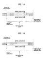
- Fig. 10A shows the layout of physical address with respect to a single-side dual-layer disc of a PTP method (hereinafter referred to as a PTP disc).
- Fig. 10B shows the layout of physical address with respect to a single-side dual-layer disc of an OTP method (hereinafter referred to as an OTP disc).
- the DVD disc has an Information Area that includes a Lead-in Area, a Data Area, and a Lead-out Area.
- the PTP disc has the Information Area separately for each record layer.
- the OTP disc has only one Information Area, and the Data Area of each record layer is followed by a Middle Area.
- layers 0 and 1 of the PTP disc and the layer 0 of the OTP disc data reproduction is carried out from the inner circumference to the outer circumference.
- the layer 1 of the OTP disc data reproduction is carried out from the outer circumference to the inner circumference.
- Each record layer of the PTP disc has consecutive physical addresses (Physical Sector Numbers) assigned from the Lead-in Area to the Lead-out Area.
- the OTP disc has consecutive physical addresses assigned from the Lead-in Area to the Middle Area in the layer 0, with the physical addresses of the layer 0 being inverted on a bit-by-bit basis to be provided as the physical addresses of the layer 1, resulting in the physical addresses of the layer 1 increasing from the Middle Area to the Lead-out Area.
- the first address of the Data Area of the layer 1 is a bit-inverted address of the last address of the layer 0.
- both the layer 0 and the layer 1 have a spiral direction extending from the inner circumference to the outer circumference of the disc (the optical pickup moves from the inner side to the outer side if tracking is left engaged).
- the spiral direction of the layer 0 extends from the inner circumference to the outer circumference of the disc whereas the spiral direction of the layer 1 extends from the outer circumference to the inner circumference of the disc.
- a record medium having a multilayered structure may be provided in a format corresponding to the PTP method or the OTP method in the same manner.
- a single-side dual-layer DVD+RW medium OTP method
- OTP method a single-side dual-layer DVD+RW medium
- this DVD+RW medium has the same track and address structure as the currently-available single-side dual-layer DVD-ROM.
- the recording of layer 1 (the second record layer) will be examined below.
- the spiral direction of a track in the layer 1 extends from the outer circumference to the inner circumference when an OPC process is performed on the write trial area (PCA area) provided in the layer 1 (the second record layer).
- the PCA area is generally comprised of a test area and a count area.
- the test area on which the write trial is performed is divided into 100 partitions (sub-areas), and each partition is comprised of 15 frames.
- a single OPC process uses a single partition (on a partition-by-partition basis). Emission power is changed multiple times in a stepwise manner with respect to the 15 frames included in the partition when performing a write trial (test recording).
- the partition on which the write trail has been performed is reproduced, and optimum recording power is determined based on the results of reproduced signals RF.
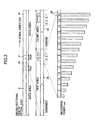
- the PCA area partition of the layer 1 (the second record layer) is successively used from the outer circumference to the inner circumference as shown in Fig. 12-(b).
- the write trial is performed such that the reproduced RF signal obtained from the write-trial portion has a waveform as schematically illustrated in Fig. 12-(c).
- recording is made by use of LD power ranging from the minimum level to the maximum level such that the range covers optimum recording power.
- the partition on which the write trial has been performed is reproduced thereby to determine optimum recording power based on the reproduced record quality.
- a description has been given with reference to a case in which write power for the write trial is changed from the minimum level to the maximum level. Alternatively, the write power may be changed from the maximum level to the minimum level.
- a seek operation is completed at an address (seek completion point) slightly ahead of the target address. Thereafter, tracking is engaged to wait for the target address until the target address is encountered. When the target address is encountered, recording or reproduction starts. This is a conventional mode of control (see Fig. 12-(d)). Since a write trial is performed on a partition by use of the OPC operation, and the result of the write trial is checked, at least one recording action and at least one reproducing action are carried out at target addresses during a series of OPC operations.
- the portion where recording is made through the write trial of the OPC operation ("USED" portion of Fig. 12-(b) and portions 1 ⁇ 2 ⁇ 3 ⁇ of Fig. 12-(c)) is subjected to the write trial that uses LD power ranging from the minimum level to the maximum level such as to cover optimum recording power. Some of the portion may thus have been recorded with excessively strong recording power. Such medium portion ends up having an overly-written recorded state, and its reflective index may be excessively low. In such portion, servo operations and/or address read operations may have an increased chance of instability, compared with portions where recording is made by use of normal, optimum recording power.
- failure may also occur due to the overlapping of PCA areas attributable to the overlapping of record layers.
- the object of the invention is to provide for a write trial in a write-trial area for determining optimum recording power to be always performed in a stable manner.
- a method of controlling a write trial process, which is performed, with respect to an optical record medium having a write trial area on a track having a spiral form, by changing emission power in a stepwise manner on a sub-area-by-sub-area basis where the write trial area is divided into sub-areas corresponding to respective changes of the emission power is configured such that the write trial is performed by using the sub-areas of the write trial area successively from an inner circumference side of the medium to an outer circumference side of the medium if a spiral direction of the track extends from the outer circumference side of the medium to the inner circumference side of the medium.
- the sub-areas of the write trial area are used successively from the inner circumference side of the medium to the outer circumference side of the medium with respect to the spiral direction that extends from the outer circumference side of the medium to the inner circumference side of the medium.
- the write trial process is performed by accessing a sub-area portion of interest without accessing the sub-area portion having undergone the write trial. Servo control and address read can thus be stabilized, and a seek operation toward the sub-area of interest is also stabilized, which results in a stable write trial process.
- a method of controlling a write trial process which is performed, with respect to a record layer of an optical record medium having a plurality of record layers each having a write trial area on a track having a spiral form, by changing emission power in a stepwise manner on a sub-area-by-sub-area basis where the write trial area is divided into sub-areas corresponding to respective changes of the emission power, includes a step of identifying a spiral direction of the track in the record layer to be recorded, and a step of performing the write trial by using the sub-areas of the write trial area successively from an inner circumference side of the medium to an outer circumference side of the medium if the identifying of the spiral direction indicates that the record layer to be recorded has the spiral direction of the track extending from the outer circumference side of the medium to the inner circumference side of the medium, and performing the write trial by using the sub-areas of the write trial area successively from the outer circumference side of the medium to the inner circumference side of the medium if the identifying of the
- the sub-areas of the write trial area are used successively from the inner circumference side of the medium to the outer circumference side of the medium with respect to the spiral direction that extends from the outer circumference side of the medium to the inner circumference side of the medium, and the sub-areas of the write trial area are used successively from the outer circumference side of the medium to the inner circumference side of the medium with respect to the spiral direction that extends from the inner circumference side of the medium to the outer circumference side of the medium.
- the method of controlling a write trial process as described above is characterized in that, in a case where the optical record medium having the plurality of record layers is an optical record medium on which recording is made by a parallel track path (PTP) method, the write trial is performed by using the sub-areas of the write trial area successively from the outer circumference side of the medium to the inner circumference side of the medium regardless of which one of the record layers is the record layer to be recorded.
- PTP parallel track path
- the optical record medium having the plurality of record layers of the PTP method all the record layers have a spiral direction that extends from the inner circumference side of the medium to the outer circumference side of the medium. Accordingly, the sub-areas of the write trial area are used successively from the outer circumference side of the medium to the inner circumference side of the medium in any record layer.
- the write trial process is performed by accessing a sub-area portion of interest without accessing the sub-area portion having undergone the write trial. Servo control and address read can thus be stabilized, and a seek operation toward the sub-area of interest is also stabilized, which results in a stable write trial process.
- the method of controlling a write trial process as described above is characterized in that, in a case where the optical record medium having the plurality of record layers is an optical record medium on which recording is made by an opposite track path (OTP) method, switching is made between the write trial performed by using the sub-areas of the write trial area successively from the inner circumference side of the medium to the outer circumference side of the medium and the write trial performed by using the sub-areas of the write trial area successively from the outer circumference side of the medium to the inner circumference side of the medium, depending on the record layer to be recorded.
- OTP opposite track path
- some record layers have a spiral direction that extends from the outer circumference side of the medium to the inner circumference side of the medium, and other record layers have a spiral direction that extends from the inner circumference side of the medium to the outer circumference side of the medium. Accordingly, a sequence in which the sub-areas of the write trial area are used is switched depending on the spiral direction of a record layer. With this provision, the write trial process is performed by accessing a sub-area portion of interest without accessing the sub-area portion having undergone the write trial, no matter which record layer is used. Servo control and address read can thus be stabilized, and a seek operation toward the sub-area of interest is also stabilized, which results in a stable write trial process.
- the method of controlling a write trial process as described above is characterized in that a step of retrieving information about the spiral direction preformatted on the optical record medium is provided when the optical record medium has the information about the spiral direction preformatted thereon, wherein the step of identifying a spiral direction identifies the spiral direction of the track in the record layer to be recorded in response to the retrieved information about the spiral direction.
- the information about the spiral direction preformatted on the optical record medium is retrieved when the optical record medium has the information about the spiral direction preformatted thereon, thereby identifying the spiral direction of the record layer in a simple and reliable manner. This achieves a stable write trial process.
- the method of controlling a write trial process as described above is such that the optical record medium is provided with, as the information about the spiral direction, preformatted information descriptive of the spiral direction on a record-layer-by-record-layer basis.
- the information about the spiral direction preformatted on the optical record medium is the preformatted information descriptive of the spiral direction on a record-layer-by-record-layer basis. With respect to each record layer, thus, the spiral direction can be directly identified, thereby attaining a stable, reliable write trial process.
- the method of controlling a write trial process as described above is such that the optical record medium is provided with, as the information about the spiral direction, preformatted information about a type of the optical record medium and preformatted information indicative of each record layer.
- the information about the spiral direction preformatted on the optical record medium is the preformatted information about a type of the optical record medium and preformatted information indicative of each record layer.
- the spiral direction can thus be indirectly identified with respect to each record layer of interest based on the information about the type of the optical record medium and the information indicative of each record layer, thereby achieving a stable, reliable write trial process. Since the information about the type of the optical record medium and the information indicative of each record layer are used as the information about the spiral direction, the identification of the spiral direction can be made by use of preexisting information.
- an optical record medium having a plurality of record layers each having a write trial area on a track having a spiral form is characterized in that information about the spiral direction is preformatted therein.
- Such optical record medium is suitable for application to the method of controlling a write trial process described above.
- the optical record medium as described above is characterized in that information descriptive of the spiral direction on a record-layer-by-record-layer basis is preformatted as the information about the spiral direction.
- optical record medium thus becomes more suitable for application to the method of controlling a write trial process described above.
- the optical record medium as described above is characterized in that information about a type of the optical record medium and information indicative of each record layer is preformatted as the information about the spiral direction.
- the optical record medium as described above is characterized in that the information about the type of the optical record medium is information indicative of either a parallel track path (PTP) method medium or an opposite track path (OTP) method medium.
- PTP parallel track path
- OTP opposite track path
- the indication of the PTP-method medium allows a determination to be made that the spiral direction extends from the inner circumference side to the outer circumference side regardless of record layers.
- the indication of the OTP-method medium indicates that the spiral direction differs depending on record layers, thereby allowing the spiral direction to be identified by obtaining the information indicative of a record layer of interest.
- the optical record medium as described above is characterized in that the information about the spiral direction is preformatted in a Lead-in Area.
- the Lead-in Area that is accessed for the purpose of obtaining unique information indicative of the optical record medium for the recording of information on the optical record medium contains the information about the spiral direction. Prior to the recording of information, thus, the information about the spiral direction can be conveniently acquired.
- the optical record medium as described above is characterized in that the optical record medium is an optical record medium on which recording is made by a parallel track path (PTP) method, and write trial areas are staggered such that the write trial area of a record layer closer to an incident light source is situated closer to an inner circumference side of the medium than is the write trial area of a record layer farther away from the incident light source.
- PTP parallel track path
- the optical record medium having a multilayered structure a plurality of record layers are superimposed one over another, so that the record layer farther away from the incident light source is affected more or less by the recorded state of the record layer closer to the incident light source.
- the sub-areas of the write trial areas of the respective record layers are used successively from the outer circumference side to the inner circumference side.
- write trial areas are staggered such that the write trial area of the record layer closer to the incident light source is situated closer to the inner circumference side of the medium than is the write trial area of the record layer farther away from the incident light source, it is possible to prevent an access to the sub-areas of the write trial area of the record layer farther away from the incident light source from being affected from the other record layer.
- the optical record medium as described above is characterized in that the optical record medium is an optical record medium on which recording is made by an opposite track path (OTP) method, and write trial areas are staggered such that the write trial area of a record layer closer to an incident light source is situated closer to an outer circumference side of the medium than is the write trial area of a record layer farther away from the incident light source.
- OTP opposite track path
- the optical record medium having a multilayered structure a plurality of record layers are superimposed one over another, so that the record layer farther away from the incident light source is affected more or less by the recorded state of the record layer closer to the incident light source.
- the sub-areas of the write trial area are used successively from the outer circumference side to the inner circumference side or used successively from the inner circumference side to the outer circumference side, depending on which record layer is the layer of interest.
- write trial areas are staggered such that the write trial area of the record layer closer to the incident light source is situated closer to the outer circumference side of the medium than is the write trial area of the record layer farther away from the incident light source, it is possible to prevent an access to the sub-areas of the write trial area of the record layer farther away from the incident light source from being affected from the other record layer.
- An optical information recording apparatus includes an optical pickup including a light source for emitting laser light to be shone on an optical record medium having a plurality of record layers each having a write trial area on a track having a spiral form, light source controlling means which attends to drive control of the light source inclusive of a power change, write trial means which performs a write trial, with respect to the write trial area of a record layer to be recorded prior to recording of information, by changing emission power in a stepwise manner on a sub-area-by-sub-area basis where the write trial area is divided into sub-areas corresponding to respective changes of the emission power, direction identifying means which identifies a spiral direction of the track in the record layer to be recorded prior to the recording of information, write-trial-mode determining means which determines, according to the identified spiral direction, a sequence in which the sub-areas of the write trial area are used in the write trial performed by the write trial means, optimum power determining means which determines optimum recording power of the light source by using the optical pickup to
- the sequence in which the sub-areas are used is determined for the write trial according to the spiral direction of a track on the record layer of interest.
- the write trial process is performed by accessing a sub-area portion of interest without accessing the sub-area portion having undergone the write trial, no matter which record layer is used. Servo control and address read can thus be stabilized, and a seek operation toward the sub-area of interest is also stabilized, which results in a stable write trial process.
- the optical information recording apparatus as described above is characterized in that the write-trial-mode determining means determines the sequence in which the sub-areas are used such that the write trial is performed by using the sub-areas of the write trial area successively from an inner circumference side of the medium to an outer circumference side of the medium if the identified spiral direction of the track extends from the outer circumference side of the medium to the inner circumference side of the medium in the record layer to be recorded, and such that the write trial is performed by using the sub-areas of the write trial area successively from the outer circumference side of the medium to the inner circumference side of the medium if the identified spiral direction of the track extends from the inner circumference side of the medium to the outer circumference side of the medium in the record layer to be recorded.
- the sub-areas of the write trial area are successively used from the inner circumference side of the medium to the outer circumference side of the medium if the spiral direction extends from the outer circumference side of the medium to the inner circumference side of the medium in the record layer, and the sub-areas of the write trial area are used successively from the outer circumference side of the medium to the inner circumference side of the medium if the spiral direction extends from the inner circumference side of the medium to the outer circumference side of the medium in the record layer.
- the write trial process is performed by accessing a sub-area portion of interest without accessing the sub-area portion having undergone the write trial, no matter which record layer is used. Servo control and address read can thus be stabilized, and a seek operation toward the sub-area of interest is also stabilized, which results in a stable write trial process.
- the optical information recording apparatus as described above is characterized in that a spiral information retrieving means is provided to retrieve information about the spiral direction preformatted on the optical record medium prior to the recording of information when the optical record medium has the information about the spiral direction preformatted thereon, wherein the direction identifying means identifies the spiral direction of the track in the record layer to be recorded in response to the information about the spiral direction retrieved by the spiral information retrieving means.
- the information about the spiral direction preformatted on the optical record medium is retrieved when the optical record medium has the information about the spiral direction preformatted thereon, thereby identifying the spiral direction of the record layer in a simple and reliable manner. This achieves a stable write trial process.
- the optical information recording apparatus as described above is such that the optical record medium is provided with, as the information about the spiral direction, preformatted information descriptive of the spiral direction on a record-layer-by-record-layer basis.
- the information about the spiral direction preformatted on the optical record medium is the preformatted information descriptive of the spiral direction on a record-layer-by-record-layer basis. With respect to each record layer, thus, the spiral direction can be directly identified, thereby attaining a stable, reliable write trial process.
- the optical information recording apparatus as described above is such that the optical record medium is provided with, as the information about the spiral direction, preformatted information about a type of the optical record medium and preformatted information indicative of each record layer.
- the information about the spiral direction preformatted on the optical record medium is the preformatted information about a type of the optical record medium and preformatted information indicative of each record layer.
- the spiral direction can thus be indirectly identified with respect to each record layer of interest based on the information about the type of the optical record medium and the information indicative of each record layer, thereby achieving a stable, reliable write trial process. Since the information about the type of the optical record medium and the information indicative of each record layer are used as the information about the spiral direction, the identification of the spiral direction can be made by use of preexisting information.
- a computer-readable record medium has an optical-information-recording-purpose program recorded therein, the program being installed in a computer provided in an optical information recording apparatus that includes an optical pickup including a light source for emitting laser light to be shone on an optical record medium having a plurality of record layers each having a write trial area on a track having a spiral form, and a light source controlling means which attends to drive control of the light source inclusive of a power change.
- the program causes a computer to perform a write trial function which performs a write trial, with respect to the write trial area of a record layer to be recorded prior to recording of information, by changing emission power in a stepwise manner on a sub-area-by-sub-area basis where the write trial area is divided into sub-areas corresponding to respective changes of the emission power, a direction identifying function which identifies a spiral direction of the track in the record layer to be recorded prior to the recording of information, a write-trial-mode determining function which determines, according to the identified spiral direction, a sequence in which the sub-areas of the write trial area are used in the write trial performed by the write trial function, an optimum power determining function which determines optimum recording power of the light source by using the optical pickup to reproduce the sub-areas having undergone the write trial performed by the write trial function, and a recording operation performing function which performs recording of information with respect to the record layer to be recorded by causing the light source controlling means to control the emission power of the light source by use of the
- the sequence in which the sub-areas are used is determined for the write trial according to the spiral direction of a track on the record layer of interest.
- the write trial process is performed by accessing a sub-area portion of interest without accessing the sub-area portion having undergone the write trial, no matter which record layer is used. Servo control and address read can thus be stabilized, and a seek operation toward the sub-area of interest is also stabilized, which results in a stable write trial process.
- the computer-readable record medium as described above is characterized in that the write-trial-mode determining function determines the sequence in which the sub-areas are used such that the write trial is performed by using the sub-areas of the write trial area successively from an inner circumference side of the medium to an outer circumference side of the medium if the identified spiral direction of the track extends from the outer circumference side of the medium to the inner circumference side of the medium in the record layer to be recorded, and such that the write trial is performed by using the sub-areas of the write trial area successively from the outer circumference side of the medium to the inner circumference side of the medium if the identified spiral direction of the track extends from the inner circumference side of the medium to the outer circumference side of the medium in the record layer to be recorded.
- the sub-areas of the write trial area are successively used from the inner circumference side of the medium to the outer circumference side of the medium if the spiral direction extends from the outer circumference side of the medium to the inner circumference side of the medium in the record layer, and the sub-areas of the write trial area are used successively from the outer circumference side of the medium to the inner circumference side of the medium if the spiral direction extends from the inner circumference side of the medium to the outer circumference side of the medium in the record layer.
- the write trial process is performed by accessing a sub-area portion of interest without accessing the sub-area portion having undergone the write trial, no matter which record layer is used. Servo control and address read can thus be stabilized, and a seek operation toward the sub-area of interest is also stabilized, which results in a stable write trial process.
- the computer-readable record medium as described above is characterized in that the computer is caused to performed a spiral information retrieving function that retrieves information about the spiral direction preformatted on the optical record medium prior to the recording of information when the optical record medium has the information about the spiral direction preformatted thereon, wherein the direction identifying function identifies the spiral direction of the track in the record layer to be recorded in response to the information about the spiral direction retrieved by the spiral information retrieving means.
- the information about the spiral direction preformatted on the optical record medium is retrieved when the optical record medium has the information about the spiral direction preformatted thereon, thereby identifying the spiral direction of the record layer in a simple and reliable manner. This achieves a stable write trial process.
- This embodiment shows an example in which the code data of the DVD-ROM format is applied to an optical information recording/reproducing apparatus serving as an optical information recording apparatus that records information (performs write-once) on a dye-system medium having a single-side dual-layer structure.
- the 8-16 modulation code (EFM modulation code) is used with mark-edge (PWM: pulse width modulation) recording.
- the present embodiment uses such a medium and record data, and causes a semiconductor laser to emit multi-pulses for recording, thereby forming record marks and spaces that represent recorded information.
- Fig. 1 is a block diagram showing the basic construction of an optical information recording/reproducing apparatus capable of recording/reproducing information.
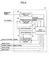
- Fig. 2 is a block diagram showing the construction of a system control device.
- a semiconductor laser (LD) 3 serving as a light source for emitting a laser beam shone on an optical record medium 2 that is a single-side dual-layer DVD+R, for example, which is rotated by a spindle motor (not shown).
- the laser beam emitted from the semiconductor laser 3 is turned into parallel rays by a collimator lens 4, and is then condensed and shone on the record layer of the optical record medium 2 after passing through a polarization beam splitter 5 and an objective lens 6. Reflective light returning from the optical record medium 2 passes through the objective lens 6 to enter the polarization beam splitter 5.
- the reflective light is reflected so as to be separated from the incident light, and passes through a detection lens 7 to enter a partitioned light receiving device (PD) 8, which has the light receiving area thereof partitioned into four areas.
- Received light signals corresponding to the respective partitioned areas of the partitioned light receiving device 8 provide bases for the a RF signal serving as an information signal, a servo signal Fo used for focusing purposes, and a servo signal Tr used for tracking purposes.
- the RF signal is subjected to current-to-voltage conversion and amplified by an IV amplifier 9 for provision to a system control device 10, in which the RF signal is processed for the purpose of outputting reproduced data serving as reproduced signals.
- the servo signal Fo for the focusing purpose and the servo signal Tr for the tracking purpose are supplied to a Fo/Tr servo control device (not shown) for use in servo control, which controls actuators (not shown) for focusing/tracking of the objective lens 6. With this, control is performed such that the laser beam is properly focused and successfully follows a track on the optical record medium 2.
- a monitor device 13 that receives a portion of the light emitted from the semiconductor laser 3 through a mirror 11 and a detection lens 12.
- a monitor electric current that is proportional to the emission power of the semiconductor laser 3 detected by the monitor device 13 is subjected to current-to-voltage conversion and amplification by an IV amplifier 14 to become a power monitor signal.
- the power monitor signal is supplied to the system control device 10 for use in APC control and the like.
- an LD driving device 15 serving as a light-source controlling unit drives and causes the semiconductor laser 3 to glow with reproduction power (read power) Pr at the time of information recording.
- the light having the reproduction power emitted from the semiconductor laser 3 is shone on the record layer of the optical record medium 2 via an optical pickup system.
- the light receiving device 8 receives the reflective light through the optical pickup system, and performs optoelectronic conversion.
- the IV amplifier 9 carries out current-to-voltage conversion and amplification to obtain a reproduced signal (RF signal).
- the monitor device 13 receives a portion of the light emitted from the semiconductor laser 3.
- the monitor power proportional to the emission power is turned into the power monitor signal through current-to-voltage conversion and amplification by the IV amplifier 14. With this provision, APC control is performed.
- a data encoder 22 and an LD-waveform controlling circuit 23 operating under the control of a host controller 21 generate a pulse controlling signal responsive to record data that is comprised of 8-16 modulation codes.
- the LD driving device 15 drives the semiconductor laser 3 with a drive current responsive to the pulse controlling signal, thereby letting the semiconductor laser 3 glow with a predetermined multi-pulse waveform.
- the emitted light is shone on the record layer of the optical record medium 2, thereby forming record marks on the optical record medium 2 for the recording of information.
- the host controller 21 supplies a bias-level-current driving signal and a peak-level-current superimposing signal to the LD driving device 15 in order to control the emission level of space/peak power.
- a sample/hold circuit 24 samples and holds the power monitor signal supplied from the IV amplifier 14 at timing when a power sample timing signal supplied from the host controller 21 changes from H to L at the time of long-space-data output (e.g., space data corresponding to more than 10T). Provision is thus made to control the space level power.
- a power sample timing signal supplied from the host controller 21 changes from H to L at the time of long-space-data output (e.g., space data corresponding to more than 10T). Provision is thus made to control the space level power.
- the peak-level-current superimposing signal is computed based on the differential efficiency ⁇ of the semiconductor laser 3, and is added to the space-level driving signal (bias-level-current driving signal), thereby supplying a drive current to the semiconductor laser 3.
- the RF signal supplied from the IV amplifier 9 is provided to the host controller 21 via a data decoder 25.
- the RF signal is also supplied to a peak/bottom detecting circuit 26, whereby a detection signal indicative of the peak/bottom level can be obtained.
- a write trial area 31 called a PCA (power calibration area) portion is situated on the innermost circumference side of the optical record medium 2.
- 32 designates a data area
- 33 designates a disc center hole.
- the write trial area 31 is comprised of a test area 34 and a count area 35.
- the test area 34 is divided and comprised of 100 partitions (sub-areas) 1 through 100, and each partition is comprised of 15 frames 36.
- a single partition is used for a single OPC operation, during which recording power is changed multiple times in a stepwise manner as a write trial as shown in the figure.
- Test signals written into respective frames 36 as a trial are reproduced, followed by determining optimum recording power based on the reproduced signals (RF signals).
- a portion of the count area 35 indicative of the number of OPC operations is updated each time an OPC operation is performed.
- the partition that needs to be reproduced immediately after a write trial and the partition that is to be used at the time of a next write trial are identified by referring to the number recorded in the count area 35.
- the partitions of the write trial area 31 are used successively from the outer circumference side to the inner circumference side as shown in Fig. 3 if the spiral direction of the track on the record layer extends from the inner circumference side to the outer circumference side, for example. (That is, the partitions are successively used in the order of No. 1, 2, and so on) If the spiral direction of the track on the record layer extends from the outer circumference side to the inner circumference side, however, the partitions of the write trial area 31 are used successively from the inner circumference side to the outer circumference side as shown in Fig. 4. (That is, the partitions are successively used in the order of No.
- Fig. 4 illustrates a case in which the count area is used from the outer circumference to the inner circumference, the count area may alternatively be used from the inner circumference to the outer circumference.
- a write trial is performed in the spiral direction within each partition (which is thus opposite to the direction in which the partitions are successively used).
- Fig. 5 is an illustrative drawing showing the processing method of Fig. 4 in a simplified manner.
- Fig. 5 shows a method wherein, if the spiral direction of the track on the record layer extends from the outer circumference to the inner circumference of the medium, the partitions of the write trial area 31 are used successively in the opposite direction from the inner circumference side to the outer circumference side of the medium. In this case, used areas (areas in which a write trial is finished) successively expand on the inner circumference side, with unused areas successively eroded on the outer circumference side.
- the way the write trial area 31 is used and the way the RF signal appears are as shown in Fig. 5-(b) and (c) after the write trial is performed.
- a seek operation is first carried out to target a seek completion point as shown in Fig. 5-(d), followed by a wait for a target until the write position of the relevant partition (target) is encountered.
- Servo and address read operations can thus be performed in a stable manner. It follows that a stable seek operation is performed, which results in a stable OPC process.
- Fig. 6 is an illustrative drawing showing the processing method of Fig. 3 in a simplified manner.
- Fig. 6 shows a method wherein, if the spiral direction of the track on the record layer extends from the inner circumference to the outer circumference of the medium, the partitions of the write trial area 31 are used successively in the opposite direction from the outer circumference side to the inner circumference side of the medium. In this case, used areas (areas in which a write trial is finished) successively expand on the outer circumference side, with unused areas successively eroded on the inner circumference side.
- the way the write trial area 31 is used and the way the RF signal appears are as shown in Fig. 6-(b) and (c) after the write trial is performed.
- a seek operation is first carried out to target a seek completion point as shown in Fig. 6-(d), followed by a wait for a target until the write position of the relevant partition (target) is encountered.
- Servo and address read operations can thus be performed in a stable manner. It follows that a stable seek operation is performed, which results in a stable OPC process.
- a dye-system medium dual-layer DVD-R
- a phase-transition-type medium dual-layer DVD+RW
- each record layer is provided with a write trial area. If the optical record medium 2 is of the PTP method that complies with the DVD-ROM format as shown in Fig. 10A and Fig. 11A, every record layer (layer 0 and layer 1) has the spiral direction of a track thereof extending from the inner circumference side of the medium to the outer circumference side of the medium.
- the spiral direction of a track differs depending on the record layer (layer 0 or layer 1). Accordingly, when an OPC operation is to be performed in the write trial area of these record layers (layer 0 and layer 1), the order in which the partitions of such an area are successively used is changed depending on the spiral direction of the track on the record layer. Namely, when a write trial is performed on the write trial area of the first record layer (layer 0), the spiral direction of the track on the first layer (layer 0) extends from the inner circumference side of the medium to the outer circumference side of the medium.
- Such operation principle is not limited to application to the dual-layer media, but is equally applicable to optical recording media having a multilayered structure with three or more layers.
- a write trial area is provided in each record layer.
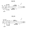
- the write trial area 31 of each record layer is preferably positioned as shown in Fig. 7A. That is, it is preferable that write trial areas 31a and 31b are staggered such that the write trial area 31a on the record layer (layer 0) that is closer to the source of incident light is situated closer to the inner circumference side on the optical record medium 2 than is the write trial area 31b provided on the record layer (layer 1) that is farther away from the source of incident light.
- the hatched areas of these write trial areas indicate used portions, and the blank areas represent unused portions, which is the same as in Fig. 6).
- the optical record medium 2 having such a multilayered structure
- a plurality of record layers are superimposed one over another, so that the second layer (layer 1) is affected more or less by the recorded state of the first record layer (layer 0).
- partitions in the write trial areas 31a and 31b of the respective record layers are used successively from the outer circumference side to the inner circumference side.
- write trial areas 31a and 31b are staggered such that the write trial area 31a of the first layer (layer 0) is situated closer to the inner circumference side of the medium than is the write trial area 31b of the second layer (layer 1), it is possible to reduce an effect of the first record layer (layer 0) on an access to the partitions of the write trial area 31b of the second record layer (layer 1).
- each record layer is provided with a write trial area.
- the write trial area 31 of each record layer is preferably positioned as shown in Fig. 7B. That is, it is preferable that write trial areas 31a and 31b are staggered such that the write trial area 31a on the record layer (layer 0) that is closer to the source of incident light is situated closer to the outer circumference side on the optical record medium 2 than is the write trial area 31b provided on the record layer (layer 1) that is farther away from the source of incident light.
- the hatched areas of these write trial areas indicate used portions, and the blank areas represent unused portions, which is the same as in Fig. 5 and Fig. 6).
- the optical record medium 2 having such a multilayered structure
- a plurality of record layers are superimposed one over another, so that the second layer (layer 1) is affected more or less by the recorded state of the first record layer (layer 0).
- partitions in the write trial areas 31a and 31b of the respective record layers are used in opposite sequences.
- write trial areas 31a and 31b are staggered such that the write trial area 31a of the first layer (layer 0) is situated closer to the outer circumference side of the medium than is the write trial area 31b of the second layer (layer 1), it is possible to reduce an effect of the first record layer (layer 0) on an access to the partitions of the write trial area 31b of the second record layer (layer 1).
- information about the spiral direction is preformatted in the optical record medium 2.
- the preformatted information about the spiral direction is retrieved prior to a recording operation, and is used to identify the spiral direction of a track in the record layer.
- information that is a direct indication of the spiral direction of a track may be preformatted separately for each record layer of the optical record medium 2, thereby allowing reliable identification of the spiral direction.
- physical information about the optical record medium 2 is preformatted by use of ADIP (Address In Pre-groove), which is address information embedded by the wobble modulation of a track (guide groove) in the Lead-in Area.
- ADIP Address In Pre-groove
- the information about the spiral direction of the track may be written as an expansion of such physical information.
- the preformatted information about the spiral direction is not limited to such a direct indication. All that is necessary is to identify the record layer to which an OPC process is applied and to identify the type of media, so that such information can be an indirect indication.
- information about the number of layers and the track-path method is recorded in the Lead-in Area. Such information may be retrieved, and is used to identify the type of a medium.
- the Data Area also contains ID information that includes information about the record layer (indicative of whether the record layer is layer 0 or layer 1).
- the address indications of layer 1 are provided as complements of the address indications of layer 0.
- the spiral direction can be known. Namely, if layer 1 is of interest in the case of an OTP-method medium, it can be known that the spiral direction extends from the outer circumference side to the inner circumference side. In the case of layer 0, it can be known that the spiral direction extends from the inner circumference side to the outer circumference side. In the case of a PTP-method medium, the spiral direction extends from the inner circumference side to the outer circumference side regardless of the layer (layer 0 or 1) of interest. According to the complement representation of addresses in the OTP-method optical record medium, the address information lets you learn whether the record layer of interest is the first record layer (layer 0) or the second record layer (layer 1). Based on the determination of the record layer, the spiral direction can be identified. Namely, the complement representation of ADIP addresses also makes it possible to readily identify the spiral direction.
- the OPC process control as illustrated in Fig. 3 or Fig. 4 may be performed for a recording operation, which is directed to the dual-layer optical record medium 2 (either the PTP method or the OTP method) in which information indicative of the spiral direction of the record layer is preformatted in the Lead-in Area of each record layer.
- the dual-layer optical record medium 2 either the PTP method or the OTP method
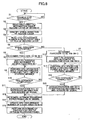
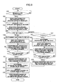
- An example of process control performed by the CPU 13 in such a case will be described with reference to a schematic flowchart shown in Fig. 8.
- This process control is performed as one of the processes that are carried out in response to a request for the recording of user data issued from a user via the host (Y at step S1), for example.
- preformatted information about the spiral direction of a record layer is retrieved from the Lead-in Area of the record layer to be recorded (S2).
- the process of step S2 is carried out as a spiral-information retrieving means or a spiral-information retrieving function.
- the spiral direction of the record layer is identified (S3). Since the information is a direct indication, the spiral direction is identified directly from the information obtained at step S2.
- the process of step S3 is performed as a direction identifying means or a direction identifying function.
- an OPC mode is engaged, and an OPC-occurrence number N is retrieved by accessing the count area 35 of the write trial area 31 provided in the record layer (S4). If the determination made at step S3 indicates that the spiral direction of a track in the record layer is a positive direction (extending from the inner circumference side to the outer circumference side) (Y at S5), the partition (target) to be subjected to a write trial is set to N+1 (S6). Namely, provision is made to use partitions of the write trial area 31 successively in a direction (extending from the outer circumference side to the inner circumference side) opposite the positive direction.
- step S3 determines whether the spiral direction of a track in the record layer is the opposite direction (N at S5).
- the partition (target) to be subjected to a write trial is set to 100-(N+1) (S7). Namely, provision is made to use the partitions of the write trial area 31 successively in the positive direction as opposed to the negative direction.
- steps S6 and S7 are performed as a write-trial-mode determining means or as a write-trial-mode determining function.
- step S6 the optical pickup is shifted through seek movement from the inner circumference side toward a seek-completion point along the track, followed by a wait for a target, and then accessing the partition N+1 (S8). This is done for the purpose of performing a write trial on the selected partition N+1 of the test area 34 provided in the write trial area 31.
- the LD driving device 15 changes the emission power of the semiconductor laser 3 successively in a stepwise manner with respect to 15 frames, thereby performing an OPC operation (write trial operation) on the partition N+1 (S9, S10).
- the processes of steps S9 and S10 are performed as a write-trial means or a write-trial process.
- access is made to the partition N+1 again to reproduce the information written as a trial, thereby producing a RF signal (S11).
- step S7 the optical pickup is shifted through seek movement from the outer circumference side toward a seek-completion point along the track, followed by a wait for a target, and then accessing the partition 100-(N+1) (S12). This is done for the purpose of performing a write trial on the selected partition 100-(N+1) of the test area 34 provided in the write trial area 31.
- the LD driving device 15 changes the emission power of the semiconductor laser 3 successively in a stepwise manner with respect to 15 frames, thereby performing an OPC operation (write trial operation) on the partition 100-(N+1) (S13, S14).
- the processes of steps S13 and S14 are performed as a write-trial means or a write-trial process.
- access is made to the partition 100-(N+1) again to reproduce the information written as a trial, thereby producing a RF signal (S15).
- the optimum recording power of the semiconductor laser 3 is determined through well-known processes (S16).
- the processes of step S11 or S15 and step S16 are performed as an optimum power determining means or a optimum power determining function.
- the OPC-occurrence number is then updated to N+1 in the count area (S17).
- step S18 is performed as a recording-operation performing means or as a recording-operation performing function.
- the OPC process control as illustrated in Fig. 3 or Fig. 4 may be performed for a recording operation, which is directed to the dual-layer optical record medium 2 (either the PTP method or the OTP method) in which information indicative of a media type (either the PTP method or the OTP method) and information indicative of a record layer (either layer 0 or layer 1) are preformatted in the Lead-in Area of each record layer.
- the dual-layer optical record medium 2 either the PTP method or the OTP method
- information indicative of a media type either the PTP method or the OTP method
- information indicative of a record layer either layer 0 or layer 1
- This process control is performed as one of the processes that are carried out in response to a request for the recording of user data issued from a user via the host (Y at step S21), for example.
- preformatted information is retrieved from the Lead-in Area of the record layer to be recorded (S22).
- the process of step S22 is carried out as a spiral-information retrieving means or a spiral-information retrieving function. Based on the information retrieved by step S22, a determination is made as to whether the type of the medium is the PTP method or the OTP method (S23).
- an OPC mode is engaged, and an OPC-occurrence number N is retrieved by accessing the count area 35 of the write trial area 31 provided in the record layer (S24).
- the partition (target) to be subjected to a write trial is set to N+1 (S26) regardless of whether the record layer is layer 0 or layer 1.
- the partition (target) to be subjected to a write trial is also set to N+1 (S26). Namely, provision is made to use the partitions of the write trial area 31 successively in the opposite direction (from the outer circumference side to the inner circumference side).
- step S23 determines whether the medium is that of the OTP method (N at S25), and if the record layer is layer 1, (N at S27), the partition (target) to be subjected to a write trial is set to 100-(N+1) (S28). Namely, provision is made to use the partitions of the write trial area 31 successively in the positive direction (from the inner circumference side to the outer circumference side).
- steps S23 and S25 are performed as a direction identifying means or as a direction identifying function.
- steps S26 and S28 are performed as a write-trial-mode determining means or as a write-trial-mode determining function.
Landscapes
- Physics & Mathematics (AREA)
- Optics & Photonics (AREA)
- Optical Recording Or Reproduction (AREA)
- Optical Head (AREA)
Abstract
Description
Claims (22)
- A method of controlling a write trial process, which is performed, with respect to an optical record medium having a write trial area on a track having a spiral form, by changing emission power in a stepwise manner on a sub-area-by-sub-area basis where the write trial area is divided into sub-areas corresponding to respective changes of the emission power, characterized in
the write trial is performed by using the sub-areas of the write trial area successively from an inner circumference side of the medium to an outer circumference side of the medium if a spiral direction of the track extends from the outer circumference side of the medium to the inner circumference side of the medium. - A method of controlling a write trial process, which is performed, with respect to a record layer of an optical record medium having a plurality of record layers each having a write trial area on a track having a spiral form, by changing emission power in a stepwise manner on a sub-area-by-sub-area basis where the write trial area is divided into sub-areas corresponding to respective changes of the emission power, characterized by comprising:a step of identifying a spiral direction of the track in the record layer to be recorded; anda step of performing the write trial by using the sub-areas of the write trial area successively from an inner circumference side of the medium to an outer circumference side of the medium if the identifying of the spiral direction indicates that the record layer to be recorded has the spiral direction of the track extending from the outer circumference side of the medium to the inner circumference side of the medium, and performing the write trial by using the sub-areas of the write trial area successively from the outer circumference side of the medium to the inner circumference side of the medium if the identifying of the spiral direction indicates that the record layer to be recorded has the spiral direction of the track extending from the inner circumference side of the medium to the outer circumference side of the medium.
- The method of controlling a write trial process as claimed in claim 2, characterized in that, in a case where the optical record medium having the plurality of record layers is an optical record medium on which recording is made by a parallel track path (PTP) method, the write trial is performed by using the sub-areas of the write trial area successively from the outer circumference side of the medium to the inner circumference side of the medium regardless of which one of the record layers is the record layer to be recorded.
- The method of controlling a write trial process as claimed in claim 2, characterized in that, in a case where the optical record medium having the plurality of record layers is an optical record medium on which recording is made by an opposite track path (OTP) method, switching is made between the write trial performed by using the sub-areas of the write trial area successively from the inner circumference side of the medium to the outer circumference side of the medium and the write trial performed by using the sub-areas of the write trial area successively from the outer circumference side of the medium to the inner circumference side of the medium, depending on the record layer to be recorded.
- The method of controlling a write trial process as claimed in claim 2, characterized in that
a step of retrieving information about the spiral direction preformatted on the optical record medium is provided when the optical record medium has the information about the spiral direction preformatted thereon, wherein said step of identifying a spiral direction identifies the spiral direction of the track in the record layer to be recorded in response to the retrieved information about the spiral direction. - The method of controlling a write trial process as claimed in claim 5, wherein the optical record medium is provided with, as the information about the spiral direction, preformatted information descriptive of the spiral direction on a record-layer-by-record-layer basis.
- The method of controlling a write trial process as claimed in claim 5, wherein the optical record medium is provided with, as the information about the spiral direction, preformatted information about a type of the optical record medium and preformatted information indicative of each record layer.
- An optical record medium having a plurality of record layers each having a write trial area on a track having a spiral form, characterized in that
information about the spiral direction is preformatted therein. - The optical record medium as claimed in claim 8, characterized in that information descriptive of the spiral direction on a record-layer-by-record-layer basis is preformatted as the information about the spiral direction.
- The optical record medium as claimed in claim 8, characterized in that information about a type of the optical record medium and information indicative of each record layer is preformatted as the information about the spiral direction.
- The optical record medium as claimed in claim 10, characterized in that the information about the type of the optical record medium is information indicative of either a parallel track path (PTP) method medium or an opposite track path (OTP) method medium.
- The optical record medium as claimed in claim 8, characterized in that the information about the spiral direction is preformatted in a Lead-in Area.
- The optical record medium as claimed in claim 8, characterized in that the optical record medium is an optical record medium on which recording is made by a parallel track path (PTP) method, and write trial areas are staggered such that the write trial area of a record layer closer to an incident light source is situated closer to an inner circumference side of the medium than is the write trial area of a record layer farther away from the incident light source.
- The optical record medium as claimed in claim 8, characterized in that the optical record medium is an optical record medium on which recording is made by an opposite track path (OTP) method, and write trial areas are staggered such that the write trial area of a record layer closer to an incident light source is situated closer to an outer circumference side of the medium than is the write trial area of a record layer farther away from the incident light source.
- An optical information recording apparatus, characterized by comprising:an optical pickup including a light source for emitting laser light to be shone on an optical record medium having a plurality of record layers each having a write trial area on a track having a spiral form;light source controlling means which attends to drive control of the light source inclusive of a power change;write trial means which performs a write trial, with respect to the write trial area of a record layer to be recorded prior to recording of information, by changing emission power in a stepwise manner on a sub-area-by-sub-area basis where the write trial area is divided into sub-areas corresponding to respective changes of the emission power;direction identifying means which identifies a spiral direction of the track in the record layer to be recorded prior to the recording of information;write-trial-mode determining means which determines, according to the identified spiral direction, a sequence in which the sub-areas of the write trial area are used in the write trial performed by the write trial means;optimum power determining means which determines optimum recording power of the light source by using the optical pickup to reproduce the sub-areas having undergone the write trial performed by the write trial means; andrecording operation performing means which performs recording of information with respect to the record layer to be recorded by causing the light source controlling means to control the emission power of the light source by use of the determined optimum recording power.
- The optical information recording apparatus as claimed in claim 15, characterized in that the write-trial-mode determining means determines the sequence in which the sub-areas are used such that the write trial is performed by using the sub-areas of the write trial area successively from an inner circumference side of the medium to an outer circumference side of the medium if the identified spiral direction of the track extends from the outer circumference side of the medium to the inner circumference side of the medium in the record layer to be recorded, and such that the write trial is performed by using the sub-areas of the write trial area successively from the outer circumference side of the medium to the inner circumference side of the medium if the identified spiral direction of the track extends from the inner circumference side of the medium to the outer circumference side of the medium in the record layer to be recorded.
- The optical information recording apparatus as claimed in claim 15, characterized in that
a spiral information retrieving means is provided to retrieve information about the spiral direction preformatted on the optical record medium prior to the recording of information when the optical record medium has the information about the spiral direction preformatted thereon,
wherein the direction identifying means identifies the spiral direction of the track in the record layer to be recorded in response to the information about the spiral direction retrieved by the spiral information retrieving means. - The optical information recording apparatus as claimed in claim 17, wherein the optical record medium is provided with, as the information about the spiral direction, preformatted information descriptive of the spiral direction on a record-layer-by-record-layer basis.
- The optical information recording apparatus as claimed in claim 17, wherein the optical record medium is provided with, as the information about the spiral direction, preformatted information about a type of the optical record medium and preformatted information indicative of each record layer.
- A computer-readable record medium having an optical-information-recording-purpose program recorded therein, the program being installed in a computer provided in an optical information recording apparatus comprising an optical pickup including a light source for emitting laser light to be shone on an optical record medium having a plurality of record layers each having a write trial area on a track having a spiral form, and a light source controlling means which attends to drive control of the light source inclusive of a power change, said program causing a computer to perform:a write trial function which performs a write trial, with respect to the write trial area of a record layer to be recorded prior to recording of information, by changing emission power in a stepwise manner on a sub-area-by-sub-area basis where the write trial area is divided into sub-areas corresponding to respective changes of the emission power,a direction identifying function which identifies a spiral direction of the track in the record layer to be recorded prior to the recording of information;a write-trial-mode determining function which determines, according to the identified spiral direction, a sequence in which the sub-areas of the write trial area are used in the write trial performed by the write trial function;an optimum power determining function which determines optimum recording power of the light source by using the optical pickup to reproduce the sub-areas having undergone the write trial performed by the write trial function; anda recording operation performing function which performs recording of information with respect to the record layer to be recorded by causing the light source controlling means to control the emission power of the light source by use of the determined optimum recording power.
- The computer-readable record medium as claimed in claim 20, characterized in that the write-trial-mode determining function determines the sequence in which the sub-areas are used such that the write trial is performed by using the sub-areas of the write trial area successively from an inner circumference side of the medium to an outer circumference side of the medium if the identified spiral direction of the track extends from the outer circumference side of the medium to the inner circumference side of the medium in the record layer to be recorded, and such that the write trial is performed by using the sub-areas of the write trial area successively from the outer circumference side of the medium to the inner circumference side of the medium if the identified spiral direction of the track extends from the inner circumference side of the medium to the outer circumference side of the medium in the record layer to be recorded.
- The computer-readable record medium as claimed in claim 20, characterized in that
the computer is caused to performed a spiral information retrieving function that retrieves information about the spiral direction preformatted on the optical record medium prior to the recording of information when the optical record medium has the information about the spiral direction preformatted thereon,
wherein the direction identifying function identifies the spiral direction of the track in the record layer to be recorded in response to the information about the spiral direction retrieved by the spiral information retrieving means.
Applications Claiming Priority (3)
| Application Number | Priority Date | Filing Date | Title |
|---|---|---|---|
| JP2003083347 | 2003-03-25 | ||
| JP2003083347A JP2004295940A (en) | 2003-03-25 | 2003-03-25 | Test writing process control method, optical recording medium, optical information recording device, optical information recording program, and storage medium |
| PCT/JP2004/003912 WO2004086377A1 (en) | 2003-03-25 | 2004-03-23 | Method for controlling trial write onto optical recording medium |
Publications (3)
| Publication Number | Publication Date |
|---|---|
| EP1607947A1 true EP1607947A1 (en) | 2005-12-21 |
| EP1607947A4 EP1607947A4 (en) | 2008-12-24 |
| EP1607947B1 EP1607947B1 (en) | 2011-11-09 |
Family
ID=33094952
Family Applications (1)
| Application Number | Title | Priority Date | Filing Date |
|---|---|---|---|
| EP04722675A Expired - Lifetime EP1607947B1 (en) | 2003-03-25 | 2004-03-23 | Method for controlling trial write onto optical recording medium |
Country Status (5)
| Country | Link |
|---|---|
| US (1) | US20050025013A1 (en) |
| EP (1) | EP1607947B1 (en) |
| JP (1) | JP2004295940A (en) |
| CN (1) | CN100428337C (en) |
| WO (1) | WO2004086377A1 (en) |
Families Citing this family (30)
| Publication number | Priority date | Publication date | Assignee | Title |
|---|---|---|---|---|
| JP4101666B2 (en) | 2002-01-22 | 2008-06-18 | 松下電器産業株式会社 | Information recording medium, recording apparatus, reproducing apparatus, recording method, reproducing method |
| JP2004310972A (en) * | 2003-03-25 | 2004-11-04 | Ricoh Co Ltd | Information processing device, information recording device, information processing system, information recording method, information recording program, and storage medium |
| JP3734816B2 (en) * | 2003-03-25 | 2006-01-11 | 株式会社リコー | Optical information recording apparatus, optical information recording medium, optical information recording method, program, and storage medium |
| CN101101761A (en) | 2003-10-03 | 2008-01-09 | 日本先锋公司 | Information recording medium, and information recording apparatus and method |
| JP2005285254A (en) * | 2004-03-30 | 2005-10-13 | Mitsubishi Electric Corp | Optical disc recording method and optical disc |
| CN101188123B (en) * | 2004-04-09 | 2010-12-01 | 日本胜利株式会社 | Information recording medium and recording method of information recording medium |
| JP4424211B2 (en) | 2004-04-09 | 2010-03-03 | 日本ビクター株式会社 | Information recording medium recording method and recording apparatus |
| WO2006003979A1 (en) * | 2004-07-05 | 2006-01-12 | Pioneer Corporation | Information recording medium, information recording device and method, and computer program |
| KR100667766B1 (en) | 2004-10-23 | 2007-01-11 | 삼성전자주식회사 | Information storage media, recording / reproducing apparatus, and recording / reproducing method |
| JP2006127593A (en) * | 2004-10-27 | 2006-05-18 | Ricoh Co Ltd | Information recording method and information recording apparatus |
| KR20060082513A (en) * | 2005-01-12 | 2006-07-19 | 엘지전자 주식회사 | Recording medium and recording method and recording apparatus of recording medium |
| EP1837865A4 (en) * | 2005-01-14 | 2008-12-17 | Pioneer Corp | Information recording device and method, and recording control computer program |
| JP4445507B2 (en) * | 2005-01-14 | 2010-04-07 | パイオニア株式会社 | Recording apparatus, recording method, and computer program |
| TWI358063B (en) * | 2005-01-14 | 2012-02-11 | Pioneer Corp | Recording medium, recording apparatus and recordin |
| TWI345778B (en) * | 2005-01-14 | 2011-07-21 | Pioneer Corp | Recording medium, recording apparatus and recording method |
| JP3812584B1 (en) * | 2005-02-16 | 2006-08-23 | 三菱電機株式会社 | Optical disc and optical disc apparatus |
| US8755258B2 (en) | 2005-02-16 | 2014-06-17 | Mitsubishi Electric Corporation | Optical disc and optical disc device |
| US8248907B2 (en) | 2005-02-16 | 2012-08-21 | Mitsubishi Electric Corporation | Optical disc and optical disc device |
| US8213290B2 (en) * | 2005-02-16 | 2012-07-03 | Mitsubishi Electric Corporation | Optical disc and optical disc device |
| KR20070003511A (en) * | 2005-06-30 | 2007-01-05 | 엘지전자 주식회사 | Recording medium and recording medium recording / reproducing method and apparatus |
| JP2007080367A (en) * | 2005-09-13 | 2007-03-29 | Toshiba Corp | Information storage medium, information recording method, and information reproducing apparatus |
| US20070097808A1 (en) * | 2005-11-02 | 2007-05-03 | Sumitaka Maruyama | Information storage medium, recording method, and recording apparatus |
| JP2007149194A (en) * | 2005-11-25 | 2007-06-14 | Sanyo Electric Co Ltd | Test disk and drive testing method |
| US7875274B2 (en) * | 2005-12-16 | 2011-01-25 | The Board Of Trustees Of The Leland Stanford Junior University | Protein modulators of resistance to alkylating agents |
| JP4810519B2 (en) * | 2007-09-14 | 2011-11-09 | 株式会社リコー | Multilayer write-once optical recording medium, recording method therefor, and recording apparatus |
| TWI415120B (en) | 2008-01-23 | 2013-11-11 | Sunplus Technology Co Ltd | Recording power calibrating method for improving seeking stability on recording power calibration area |
| KR20110059861A (en) * | 2008-09-29 | 2011-06-07 | 파나소닉 주식회사 | Information recording medium, recording method and reproduction method |
| JP5735202B2 (en) | 2009-07-03 | 2015-06-17 | ソニー株式会社 | Recordable optical disc, recording apparatus, and recording method |
| JP2011014203A (en) | 2009-07-03 | 2011-01-20 | Sony Corp | Recordable optical disc, recording device, recording method, and reproducing device |
| EP3306610A4 (en) * | 2015-05-26 | 2019-01-23 | Sony Corporation | RECORDING DEVICE, RECORDING METHOD, OPTICAL RECORDING MEDIUM, REPRODUCING DEVICE, REPRODUCING METHOD |
Family Cites Families (13)
| Publication number | Priority date | Publication date | Assignee | Title |
|---|---|---|---|---|
| JPH113550A (en) * | 1997-06-12 | 1999-01-06 | Nikon Corp | Information recording / reproducing device |
| JP3720624B2 (en) * | 1999-04-26 | 2005-11-30 | 株式会社リコー | Optical disc recording / reproducing apparatus and optimum recording power value determination method for optical disc |
| JP3834165B2 (en) * | 1999-06-30 | 2006-10-18 | 株式会社リコー | Laser diode driver |
| JP3720644B2 (en) * | 1999-08-06 | 2005-11-30 | 株式会社リコー | Optimal recording power value determination method and optimal recording power value determination device |
| JP2001126255A (en) * | 1999-10-22 | 2001-05-11 | Sony Corp | Optical recording method and optical recording device |
| US6914875B2 (en) * | 2000-06-22 | 2005-07-05 | Tdk Corporation | Optical recording medium and optical recording method |
| US20020136122A1 (en) * | 2001-03-21 | 2002-09-26 | Kazuhiko Nakano | Optical information record medium, method of recording information on optical information record medium, and information recording apparatus |
| JP2003022532A (en) * | 2001-07-06 | 2003-01-24 | Columbia Music Entertainment Inc | Optical information recording medium and method and device for optical information recording |
| US6845071B2 (en) * | 2001-03-28 | 2005-01-18 | Matsushita Electric Industrial Co., Ltd. | Optical disc apparatus and recording power determining method thereof |
| JP3869743B2 (en) * | 2001-03-28 | 2007-01-17 | 松下電器産業株式会社 | Recording power determination method and recording power determination device |
| JP3793052B2 (en) * | 2001-07-16 | 2006-07-05 | 株式会社東芝 | Optical disc apparatus and recording condition setting method for a plurality of recording layers |
| JP3964282B2 (en) * | 2002-08-23 | 2007-08-22 | 株式会社リコー | Recording condition setting method, program, recording medium, and information recording apparatus |
| JP3863497B2 (en) * | 2002-12-04 | 2006-12-27 | 株式会社リコー | Optical information recording apparatus and optical information processing apparatus |
-
2003
- 2003-03-25 JP JP2003083347A patent/JP2004295940A/en active Pending
-
2004
- 2004-03-23 CN CNB2004800063912A patent/CN100428337C/en not_active Expired - Fee Related
- 2004-03-23 EP EP04722675A patent/EP1607947B1/en not_active Expired - Lifetime
- 2004-03-23 WO PCT/JP2004/003912 patent/WO2004086377A1/en not_active Ceased
- 2004-09-03 US US10/933,465 patent/US20050025013A1/en not_active Abandoned
Also Published As
| Publication number | Publication date |
|---|---|
| WO2004086377A1 (en) | 2004-10-07 |
| JP2004295940A (en) | 2004-10-21 |
| CN100428337C (en) | 2008-10-22 |
| US20050025013A1 (en) | 2005-02-03 |
| EP1607947B1 (en) | 2011-11-09 |
| EP1607947A4 (en) | 2008-12-24 |
| CN1759441A (en) | 2006-04-12 |
Similar Documents
| Publication | Publication Date | Title |
|---|---|---|
| EP1607947B1 (en) | Method for controlling trial write onto optical recording medium | |
| US7151728B2 (en) | Optical disc apparatus and recording power determining method thereof | |
| EP1498886A2 (en) | Test recording process control method and optical disk apparatus | |
| EP1607946A1 (en) | Optical information recording device, information processing device, optical information recording medium, optical information recording method, program, and recording medium | |
| EP1693836B1 (en) | Recording method, recorder and recording medium | |
| US7209419B2 (en) | Recording condition compensation method, program, recording medium, and information recording apparatus | |
| KR100703148B1 (en) | Information recording apparatus and method, and information recording medium | |
| JP2004327038A (en) | Optical recording medium | |
| US8335140B2 (en) | Optical disc drive for recording or reproducing data on a multilayer optical disc with a layer identification region | |
| KR100675582B1 (en) | Optical disc recording / playback method and recording / playback apparatus, and optical disc | |
| EP1548731B1 (en) | Optical disk apparatus, method for controlling the same, and recording medium | |
| KR20080005266A (en) | Recording system to set recording strategy | |
| CN101477818B (en) | CD device | |
| WO2005001823A1 (en) | Information storage medium and method and apparatus for recording/reproducing data | |
| JP4249663B2 (en) | Information recording medium, and information recording apparatus and method | |
| JP4102743B2 (en) | Information recording / reproducing apparatus, information recording / reproducing method, and program | |
| JP4321469B2 (en) | Disc recording apparatus and method, and recording control program | |
| US7961567B2 (en) | Optical disk apparatus | |
| US20070165492A1 (en) | Recording type optical disc apparatus and optical disc medium | |
| JP2004265475A (en) | Optical disc device and focus control method therefor | |
| JP2006127752A (en) | Optical information recording medium | |
| JP2006172569A (en) | Information recording medium, information recording device and method, and computer program | |
| HK1090740B (en) | Information recording apparatus and method | |
| JP2006323978A (en) | Information recording/reproducing method, and information recording/reproducing device |
Legal Events
| Date | Code | Title | Description |
|---|---|---|---|
| PUAI | Public reference made under article 153(3) epc to a published international application that has entered the european phase |
Free format text: ORIGINAL CODE: 0009012 |
|
| 17P | Request for examination filed |
Effective date: 20050812 |
|
| AK | Designated contracting states |
Kind code of ref document: A1 Designated state(s): AT BE BG CH CY CZ DE DK EE ES FI FR GB GR HU IE IT LI LU MC NL PL PT RO SE SI SK TR |
|
| AX | Request for extension of the european patent |
Extension state: AL LT LV MK |
|
| DAX | Request for extension of the european patent (deleted) | ||
| RBV | Designated contracting states (corrected) |
Designated state(s): DE ES FR GB IT NL |
|
| A4 | Supplementary search report drawn up and despatched |
Effective date: 20081120 |
|
| 17Q | First examination report despatched |
Effective date: 20090914 |
|
| GRAP | Despatch of communication of intention to grant a patent |
Free format text: ORIGINAL CODE: EPIDOSNIGR1 |
|
| GRAS | Grant fee paid |
Free format text: ORIGINAL CODE: EPIDOSNIGR3 |
|
| GRAA | (expected) grant |
Free format text: ORIGINAL CODE: 0009210 |
|
| AK | Designated contracting states |
Kind code of ref document: B1 Designated state(s): DE ES FR GB IT NL |
|
| REG | Reference to a national code |
Ref country code: GB Ref legal event code: FG4D |
|
| REG | Reference to a national code |
Ref country code: DE Ref legal event code: R096 Ref document number: 602004035221 Country of ref document: DE Effective date: 20120209 |
|
| REG | Reference to a national code |
Ref country code: NL Ref legal event code: VDEP Effective date: 20111109 |
|
| PG25 | Lapsed in a contracting state [announced via postgrant information from national office to epo] |
Ref country code: NL Free format text: LAPSE BECAUSE OF FAILURE TO SUBMIT A TRANSLATION OF THE DESCRIPTION OR TO PAY THE FEE WITHIN THE PRESCRIBED TIME-LIMIT Effective date: 20111109 |
|
| PG25 | Lapsed in a contracting state [announced via postgrant information from national office to epo] |
Ref country code: IT Free format text: LAPSE BECAUSE OF FAILURE TO SUBMIT A TRANSLATION OF THE DESCRIPTION OR TO PAY THE FEE WITHIN THE PRESCRIBED TIME-LIMIT Effective date: 20111109 |
|
| PLBE | No opposition filed within time limit |
Free format text: ORIGINAL CODE: 0009261 |
|
| STAA | Information on the status of an ep patent application or granted ep patent |
Free format text: STATUS: NO OPPOSITION FILED WITHIN TIME LIMIT |
|
| 26N | No opposition filed |
Effective date: 20120810 |
|
| REG | Reference to a national code |
Ref country code: DE Ref legal event code: R097 Ref document number: 602004035221 Country of ref document: DE Effective date: 20120810 |
|
| PG25 | Lapsed in a contracting state [announced via postgrant information from national office to epo] |
Ref country code: ES Free format text: LAPSE BECAUSE OF FAILURE TO SUBMIT A TRANSLATION OF THE DESCRIPTION OR TO PAY THE FEE WITHIN THE PRESCRIBED TIME-LIMIT Effective date: 20120220 |
|
| REG | Reference to a national code |
Ref country code: FR Ref legal event code: PLFP Year of fee payment: 13 |
|
| REG | Reference to a national code |
Ref country code: FR Ref legal event code: PLFP Year of fee payment: 14 |
|
| PGFP | Annual fee paid to national office [announced via postgrant information from national office to epo] |
Ref country code: FR Payment date: 20170322 Year of fee payment: 14 Ref country code: DE Payment date: 20170322 Year of fee payment: 14 |
|
| PGFP | Annual fee paid to national office [announced via postgrant information from national office to epo] |
Ref country code: GB Payment date: 20170322 Year of fee payment: 14 |
|
| REG | Reference to a national code |
Ref country code: DE Ref legal event code: R119 Ref document number: 602004035221 Country of ref document: DE |
|
| GBPC | Gb: european patent ceased through non-payment of renewal fee |
Effective date: 20180323 |
|
| PG25 | Lapsed in a contracting state [announced via postgrant information from national office to epo] |
Ref country code: DE Free format text: LAPSE BECAUSE OF NON-PAYMENT OF DUE FEES Effective date: 20181002 |
|
| PG25 | Lapsed in a contracting state [announced via postgrant information from national office to epo] |
Ref country code: GB Free format text: LAPSE BECAUSE OF NON-PAYMENT OF DUE FEES Effective date: 20180323 |
|
| PG25 | Lapsed in a contracting state [announced via postgrant information from national office to epo] |
Ref country code: FR Free format text: LAPSE BECAUSE OF NON-PAYMENT OF DUE FEES Effective date: 20180331 |