EP1607783A1 - Lens changeover device for a camera - Google Patents
Lens changeover device for a camera Download PDFInfo
- Publication number
- EP1607783A1 EP1607783A1 EP05012639A EP05012639A EP1607783A1 EP 1607783 A1 EP1607783 A1 EP 1607783A1 EP 05012639 A EP05012639 A EP 05012639A EP 05012639 A EP05012639 A EP 05012639A EP 1607783 A1 EP1607783 A1 EP 1607783A1
- Authority
- EP
- European Patent Office
- Prior art keywords
- holder frame
- optical element
- rest position
- working position
- switch device
- Prior art date
- Legal status (The legal status is an assumption and is not a legal conclusion. Google has not performed a legal analysis and makes no representation as to the accuracy of the status listed.)
- Granted
Links
Images


Classifications
-
- G—PHYSICS
- G02—OPTICS
- G02B—OPTICAL ELEMENTS, SYSTEMS OR APPARATUS
- G02B7/00—Mountings, adjusting means, or light-tight connections, for optical elements
- G02B7/02—Mountings, adjusting means, or light-tight connections, for optical elements for lenses
- G02B7/14—Mountings, adjusting means, or light-tight connections, for optical elements for lenses adapted to interchange lenses
Definitions
- the present invention relates to a device for mounting and demounting an optical element, and more specifically, for inserting an optical element into an optical lens system, such as an image forming lens system of, in particular, a broadcasting television camera and removing the same from the optical lens system.
- an optical lens system such as an image forming lens system of, in particular, a broadcasting television camera
- An image forming lens system namely a taking lens system, for such an ENG camera is provided with an optical element switch device for inserting an optical element such as a converter or extender lens into an optical path of the taking lens system for altering the focal length of the taking lens system and removing the optical element from the taking lens system.
- One of extender switching devices that is disclosed in, for example, Japanese Unexamined Patent Publication No. 9-171135 includes first and second extenders pivotally mounted on a common pivot shaft so as to be moves between a working position and rest positions independently through operation of a manual operation lever.
- the extender switching device is provided with urging means such as a tension spring for retaining an extender lens in a stationary state in a predetermined position and a damper mechanism for preventing generation of hitting sound and/or vibrations when the extender lens is moved from the rest position to the working position or vice versa.
- urging means such as a tension spring for retaining an extender lens in a stationary state in a predetermined position and a damper mechanism for preventing generation of hitting sound and/or vibrations when the extender lens is moved from the rest position to the working position or vice versa.
- the extender switching device disclosed in the publication needs a number of constituent parts for the retainer spring find the damper mechanism and increases the number of man-hour for fabrication in consequence.
- an optical element switch device for bringing an optical element such as, for example, an extender lens, a ratio converter lens, or an optical filter for transmitting light according to wavelengths, into an optical path of an image forming lens system and removing it from the optical path that comprise a holder frame for fixedly holding the optical element which is movable between a rest position in which the optical element is put out of the optical path of the image forming lens system and a working position in which the optical element is put in the optical path of the image forming lens system, operating means for causing movement of the holder frame between the rest position and the working position, and urging means in the form of a leaf spring fixedly supported on a stationary part such as a housing of the device for applying urging force against the holder frame during movement of the holder frame between the rest position and the working position and inverting the urging force in direction with respect to the holder frame between the rest position and the working position,.
- an optical element such as, for example, an extender lens, a ratio converter lens, or an optical filter for
- the urging means keeps itself applying urging force against the holder frame in a direction of movement and reverses directions of urging force with respect to the holder frame between the rest position and the working position.
- the holder frame, and hence the optical element held by the holder frame is firmly retained in an intended position, either the rest position or the working position, and prevented from generating hitting noises when reaching the rest position or the working position and causing cranky movement between the rest position and the working position.
- the directional inversion of urging force is distinctly recognizable, so that the optical element switch device is improved in operationality.
- the optical element switch device of the present invention eliminates installation of a tension spring and a damper mechanism and, in consequence, is simple in structure.
- the urging means may comprise a leaf spring that is secured at one or both of opposite ends thereof to the stationary part, for example the housing, of the optical element switch device so as to be elastically bendable or deformable during movement of the holder frame between the rest position and the working position.
- the leaf spring secured at one end thereof has a generally V-shaped form so that the leaf spring allows another end section to be bent by a projection or a rim of the holder frame.
- the leaf spring secured at both one ends thereof comprises bent and straight sections so that the leaf spring allows itself to be deformed by a rim of the holder frame.
- the optical element switch device is especially suitably embodied as an extender switch device for inserting an extender lens into an optical lens system of for example, a broadcasting television camera such as an electronic news gathering camera and removing the same from the optical lens system.
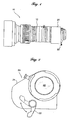
- the zoom lens 10 comprises a zoom lens part 12 and an extender part 20 having a switch lever 2 for manually switching an extender lens between working and rest positions.
- Zoom lenses generally comprise at least a focusing lens system and a zooming lens system arranged in order from the object side to the image side.
- Such a zoom lens is known in various types and takes any type well known in the art. Details of the zoom lens will not be set out in detail since their construction and operation can be easily arrived at by those skilled in the art.
- the extender part 20 includes a housing 24 in which an extender lens 26 and a switch lever 22 are incorporated.
- the switch lever 22 is manually operated to switch the extender lens 26 between a rest position (see Figure 3) in which an extender lens 26 is out of the zoom lens system and a working position (see Figure 4) in which the extender lens 26 is put in the zoom lens system through a switching mechanism which will he described later.
- Figures 3 and 4 show details of the switching mechanism for switching the extender lens 26 between the rest position and the working position, respectively.
- the extender lens 26, which has a magnifying power of, tor example X 2 and may consists of single or a plurality of lenses, is fixedly held in a holder frame 28 having a hub ring 28A through which the holder frame 20 is pivotally mounted on a pivot shaft 30 fixed to the housing 24.
- the holder frame 28 has circumferential locating faces 28B and 28C disposed at substantially diametrically opposite positions thereof.
- the locating face 28B is brought into abutment with a stopper stud 32 fitted in a threaded hole 24A formed in the housing 24 so as to retain the holder frame 28 in the rest position shown in Figure 3 when the extender lens 26 is moved out of the zoom lens system.
- the locating face 28C is brought into abutment with a stopper stud 34 fitted in a threaded hole 24B formed in the housing 24 so as to position the holder frame 28 in the working position shown in Figure 4 when the extender lens 26 is moved into the zoom lens system.
- These stopper studs 28B and 28C can be adjusted in threaded position for fine adjustment of the rest position and the working position, respectively.
- the switch lever 22 has a shaft 31 having an external gear 38 integrally formed therewith and pivotally mounted to the housing 24.
- the hub ring 28A of the holder frame 28 has an external gear 36 and a projection 44 integrally formed therewith.
- the switch lever 22 and the holder frame 28 are operationally coupled to each other through engagement between the external gears 36 and 38.
- the switching mechanism includes urging means comprising, for example in this embodiment, a generally V-shaped leaf spring 40 for preventing the holder frame 28 from generating hitting noises when the holder frame 28 hits the stopper studs 28B and 34 and causing cranky movement between the rest position and the working position.
- the V-shaped leaf spring 40 is made from a steel strip having a predetermined width and comprises a pressure arm section 40A, a base section 40C and a bent section 40B by which the pressure arm section 40A and the base section 40C are connected as an integral piece.
- the leaf spring 40 is fixed to the housing 24 by a fixing stud 42 fitted in a threaded hole 24C formed in the housing 24.
- the pressure arm section 40A cooperates with the projection 44 of the hub ring 28A of the holder frame 28 so as to urges the holder frame 28. More specifically, when operating the switch lever 22, the holder frame 28 is turned through engagement between the external gear 36 of the hub ring 28A and the external gear 38 of the shaft 31 of the switch lever 22.
- the leaf spring 40 is elastically bent downward by the projection 44 as depicted by a broken line so as thereby to keep itself applying urging force against the projection 44 of the holder frame 28,
- the leaf spring 40 urges the projection in a counterclockwise direction so as thereby to retain the holder frame 28 in the rest position.
- the leaf spring 40 urges the projection in a clockwise direction so as thereby to retain the holder frame 28 in the working position. In this manner, urging force against the holder frame 28 is inverted in direction according to the moved positions, namely the rest position and the working position, of the holder frame 28.
- the holder frame 28 In operation of the extender switching device thus structured, while the extender lens 26 is in the rest position as shown in Figure 3, the holder frame 28 is retained with the circumferential locating face 28B abutted against the stopper stud 32 due to urging force applied against the projection 44 of the hub ring 28A of the holder frame 28 in a counterclockwise direction by the leaf spring 40.
- the switch lever 22 When operating the switch lever 22 in a counterclockwise direction, the holder frame 28 is moved in a counterclockwise direction through engagement between the external gear 36 of the hub ring 28A and the external gear 38 of the shaft 31 of the switch lever 22 so as thereby to put the extender lens 26 into an optical path of the zoom lens system as shown in Figure 4.
- the urging force applied against the projection 44 of the hub ring 28A of the holder frame 28 is inverted before and after an intermediate point of the movement of the holder frame 28 from the rest position to the working position and the vice versa. While it is necessary to operate the switch lever 22 with excess force in order to cause the holder frame 28 to pass through the intermediate point of the movement against the leaf spring 40, operation of the switch lever 22 becomes easy after the intermediate point of the movement because the leaf spring 40 applies urging force to the holder frame 28 in the same direction as movement of the holder frame 28. In consequence an inversion point of urging force is distinctly recognizable, and operationality of the switch lever 22 is improved.
- the holder frame 28 is always urged by the leaf spring 40 during movement from the rest position to the working position and the vice versa, the holder frame 28 is prevented from dashing against the stopper stud 32 or 34 with the locating surface 28B or 28C, respectively, and hence, from generating hitting noises when the holder frame 28 reaches the rest position or the working position, besides prevented from causing cranky movement between the rest position and the working position.
- Figures 5 and 6 show an extender switching device 20 according to another embodiment of the present invention in which alternative urging means is employed.
- the urging means for preventing the holder frame 28 mounting an extender lens 26 therein from generating hitting noises and causing cranky movement comprises an integral piece of leaf spring 50.
- the leaf spring 50 is made from a steel strip having a predetermined width and has a generally U-shaped sections 50A between opposite end legs 50B.
- the generally U-shaped section 50A comprises a plurality of straight segments joined together at certain angles as an integral piece.
- the leaf spring 50 at the end legs 50B is fixed to the housing 24 by fixing studs 52 fitted in threaded holes 24D formed in die housing 24 so as to allow the U-shaped sections 50A to be elastically flatly deformable with external force.
- the holder frame 28 has a rim 28D formed on a rear surface thereof against which the leaf spring 50 is forced.
- the leaf spring 50 keeps itself pushing the rim 28D of the holder frame 28 in a circumferential direction with the while the holder frame 28 is moved between a rest position shown in Figure 5 and a working position shown in Figure 6. More specifically, the leaf spring 50 is deformed when the holder frame 28 moves between the rest position and the working position so that the urging force applied against the rim 28D of the holder frame 28 is inverted before and alter an in-between position between the rest position and the working position. As a result, the holder frame 28 is urged in a counterclockwise direction while the holder frame is in the rest position and, on the other hand, in a clockwise direction while the holder frame 28 is in the working position.
- the holder frame 28 While the extender lens 26 is out of the zoom lens system, the holder frame 28 is urged by the U-shaped section 50A of the led spring 50 so as to be retained in the rest position through abutment of the locating face 28B against the stopper stud 32.
- the switch lever 22 When operating the switch lever 22 so as to move the extender lens 26 into the zoom lens, the locating face 28C of the holder frame 28 is brought into abutment against the stopper stud 34, so as to retain the holder frame 28 in the working position.
- the holder frame 28 is always urged by the leaf spring 50 during movement from the rest position to the working position and the vice versa, the holder frame 28 is prevented from dashing against the stopper stud 32 or 34 with the locating surface 28B or 28C, respectively, and hence, from generating hitting noises when the holder frame 28 reaches the rest position or the working position, besides prevented from causing cranky movement between the rest position and the working position.
- Figures 7 and 8 show an extender switching device 20 according to a further embodiment of the present invention in which alternative urging means is employed.
- the urging means for preventing the holder frame 28 mounting an extender lens 26 therein from generating hitting noises and causing cranky movement comprises a cantilever type of leaf spring 60.
- the leaf spring 50 that is made from a steel strip having a predetermined width, has a generally V-shaped distal sections 60A and 60B directed inversely to each other and is fixed at an end leg 60C to the housing 24 by a fixing stud 62 fitted in a threaded hole 24D formed in the housing 24 so as to allow the V-shaped sections 60A and 60B to be elastically bendable with external force.
- the holder frame 28 has a rim 28D formed on a rear surface thereof against which the leaf spring 50 is forced.
- the leaf spring 60 keeps itself pushing the rim 28D of the holder frame 28 in a circumferential direction with the V-shaped sections 60A or 60B while the holder frame 28 is moved between a rest position shown in Figure 5 and a working position shown in Figure 6. More specifically, the leaf spring 50 is deformed when the holder frame 28 moves between the rest position and the working position so that the urging force applied against the rim 28D of the holder frame 28 is inverted before and after an in-between position between the rest position and the working position. As a result, the holder frame 28 is urged in a counterclockwise direction while the holder frame is in the rest position and, on the other hand, in a clockwise direction while the holder frame 28 is in the working position.
- the holder frame 28 While the extender lens 26 is out of the zoom lens system, the holder frame 28 is urged in a counterclockwise direction by the V-shaped section 60A so as to be retained in the rest position through abutment of the locating face 28B against the stopper stud 32.
- the holder frame 28 elastically bends the leaf spring 60 and brings the rim 28D into engagement with the V-shaped section 60B.
- the leaf spring 60 urges the holder frame 28 in a clockwise direction by the V-shaped section 60B so as thereby to retain the holder frame 28 in the working position.
- urging force against the holder frame 28 is inverted in direction at a point of movement of the holder frame 28 where engagement of the leaf spring 60 with holder frame 28 changes from the V-shaped section 60A to the V-shaped section 60B.
- the holder frame 28 is prevented from dashing against the stopper stud 32 or 34 with the locating surface 28B or 28C, respectively, and hence, from generating hitting noises when the holder frame 28 reaches the rest position or the working position, besides prevented from causing cranky movement between the rest position and the working position.
- optical element switch device of the present invention has been described as to the extender switch device embodied in a zoom lens for an ENG camera by way of example, the optical element switch device may be incorporated in various types of image forming optical lens systems.
Landscapes
- Physics & Mathematics (AREA)
- General Physics & Mathematics (AREA)
- Optics & Photonics (AREA)
- Lens Barrels (AREA)
- Structure And Mechanism Of Cameras (AREA)
- Studio Devices (AREA)
Abstract
Description
Claims (5)
- An optical element switch device (20) for bringing an optical element (26) held by a holder frame (28) supported for pivotal movement on a stationary member (24) of the optical clement switch device (20) so as to move said optical element (26) between a rest position in which said optical element (20) is put out of said optical path of said image forming lens system and a working position in which said optical element (26) is put in said optical path of said image forming lens system, into an optical path of an image forming lens system and removing the optical element (26) from the optical path, characterized by:manually operable switch means (22) for causing pivotal movement of said holder frame (28) between said rest position and said working position, and urging means (40; 50; 60) for applying urging force against said holder frame (28) during pivotal movement of said holder frame (28) between said rest position and said working position, wherein said urging means (40; 50; 60) is secured to said stationary member (24) of the optical element switch device (20) so as to invert said urging force in direction with respect to said holder frame (28) between said rest position and said working position.
- The optical element switch device as defined in claim 1, characterized in that said urging means comprises a leaf spring (40; 60) secured at one of opposite ends (40C, 60B) to said stationary support means (24) and elastically bendable during movement of said holder frame (28) between said rest position and said working position.
- The optical element switch device as defined in claim 1, characterized in that said urging means comprises a leaf spring (50) secured at opposite ends (50B) to said stationary support means (24) and having bent and straight sections so as to be elastically deformable in shape during movement of said holder frame (28) between said rest position and said working position.
- The optical element switch device as defined in any one of the preceding claims 1 through 3, characterized in that said holder frame (28) has at least one projection (44; 28D) against which said urging means applies said urging force.
- The optical element switch device as defined in any one of the preceding claims I through 4, characterized in that said optical element (26) comprises an extender lens for altering a focal length of said image forming lens system.
Applications Claiming Priority (2)
| Application Number | Priority Date | Filing Date | Title |
|---|---|---|---|
| JP2004175652A JP2005352395A (en) | 2004-06-14 | 2004-06-14 | Insertion/extraction device of optical element |
| JP2004175652 | 2004-06-14 |
Publications (2)
| Publication Number | Publication Date |
|---|---|
| EP1607783A1 true EP1607783A1 (en) | 2005-12-21 |
| EP1607783B1 EP1607783B1 (en) | 2007-05-02 |
Family
ID=34937399
Family Applications (1)
| Application Number | Title | Priority Date | Filing Date |
|---|---|---|---|
| EP05012639A Expired - Lifetime EP1607783B1 (en) | 2004-06-14 | 2005-06-13 | Lens changeover device for a camera |
Country Status (5)
| Country | Link |
|---|---|
| US (1) | US7347565B2 (en) |
| EP (1) | EP1607783B1 (en) |
| JP (1) | JP2005352395A (en) |
| CN (1) | CN100472265C (en) |
| DE (1) | DE602005001025T2 (en) |
Families Citing this family (5)
| Publication number | Priority date | Publication date | Assignee | Title |
|---|---|---|---|---|
| US20050080934A1 (en) | 2003-09-30 | 2005-04-14 | Cota-Robles Erik C. | Invalidating translation lookaside buffer entries in a virtual machine (VM) system |
| JP5947616B2 (en) * | 2012-05-17 | 2016-07-06 | キヤノン株式会社 | Lens barrel and imaging device |
| JP6053464B2 (en) * | 2012-11-15 | 2016-12-27 | キヤノン株式会社 | Lens barrel and optical equipment |
| JP6305174B2 (en) * | 2014-04-10 | 2018-04-04 | キヤノン株式会社 | Optical equipment |
| JP2024050180A (en) * | 2022-09-29 | 2024-04-10 | 株式会社トプコン | Variable magnification optical system and ophthalmic device |
Citations (3)
| Publication number | Priority date | Publication date | Assignee | Title |
|---|---|---|---|---|
| US4038671A (en) * | 1975-08-29 | 1977-07-26 | Agfa-Gevaert Aktiengesellschaft | Photographic apparatus with two picture taking lenses |
| JPH09133958A (en) * | 1995-11-10 | 1997-05-20 | Fuji Photo Film Co Ltd | Film unit with lens |
| JP2001133870A (en) * | 1999-11-01 | 2001-05-18 | Fuji Photo Film Co Ltd | Film unit with lens |
Family Cites Families (6)
| Publication number | Priority date | Publication date | Assignee | Title |
|---|---|---|---|---|
| US4681418A (en) * | 1984-08-23 | 1987-07-21 | Canon Kabushiki Kaisha | Camera |
| US5751353A (en) * | 1994-12-16 | 1998-05-12 | Fuji Photo Optical Co., Ltd. | Switching apparatus for TV lens unit switching |
| US5765049A (en) * | 1995-06-26 | 1998-06-09 | Canon Kabushiki Kaisha | Optical apparatus having lens system change-over mechanism |
| JP3512544B2 (en) | 1995-12-19 | 2004-03-29 | 富士写真光機株式会社 | Extender switching device |
| JP2000241867A (en) * | 1999-02-19 | 2000-09-08 | Matsushita Electric Ind Co Ltd | Movable filter device |
| US6140872A (en) * | 1999-10-28 | 2000-10-31 | Burr-Brown Corporation | Offset-compensated amplifier input stage and method |
-
2004
- 2004-06-14 JP JP2004175652A patent/JP2005352395A/en active Pending
-
2005
- 2005-06-09 CN CNB2005100765428A patent/CN100472265C/en not_active Expired - Fee Related
- 2005-06-13 EP EP05012639A patent/EP1607783B1/en not_active Expired - Lifetime
- 2005-06-13 DE DE602005001025T patent/DE602005001025T2/en not_active Expired - Lifetime
- 2005-06-14 US US11/151,350 patent/US7347565B2/en not_active Expired - Fee Related
Patent Citations (3)
| Publication number | Priority date | Publication date | Assignee | Title |
|---|---|---|---|---|
| US4038671A (en) * | 1975-08-29 | 1977-07-26 | Agfa-Gevaert Aktiengesellschaft | Photographic apparatus with two picture taking lenses |
| JPH09133958A (en) * | 1995-11-10 | 1997-05-20 | Fuji Photo Film Co Ltd | Film unit with lens |
| JP2001133870A (en) * | 1999-11-01 | 2001-05-18 | Fuji Photo Film Co Ltd | Film unit with lens |
Non-Patent Citations (2)
| Title |
|---|
| PATENT ABSTRACTS OF JAPAN vol. 1997, no. 09 30 September 1997 (1997-09-30) * |
| PATENT ABSTRACTS OF JAPAN vol. 2000, no. 22 9 March 2001 (2001-03-09) * |
Also Published As
| Publication number | Publication date |
|---|---|
| DE602005001025D1 (en) | 2007-06-14 |
| EP1607783B1 (en) | 2007-05-02 |
| CN100472265C (en) | 2009-03-25 |
| JP2005352395A (en) | 2005-12-22 |
| US20050276591A1 (en) | 2005-12-15 |
| US7347565B2 (en) | 2008-03-25 |
| DE602005001025T2 (en) | 2007-12-27 |
| CN1721908A (en) | 2006-01-18 |
Similar Documents
| Publication | Publication Date | Title |
|---|---|---|
| US5943169A (en) | Image blur preventing device | |
| EP1906233B1 (en) | Imaging device | |
| KR20090062574A (en) | Lens shifter | |
| EP1607783B1 (en) | Lens changeover device for a camera | |
| JP2006091153A (en) | Optical element holding mechanism, lens barrel and optical device | |
| JP5093036B2 (en) | Lens barrel and imaging device | |
| JP4906802B2 (en) | Zoom lens barrel | |
| JP2005274837A (en) | Eccentricity adjustment method of zoom lens | |
| JP4652152B2 (en) | Lens drive device | |
| JP5046784B2 (en) | Lens barrel and camera device | |
| JP2017106950A (en) | Lens barrel and optical instrument | |
| JP4908984B2 (en) | Variable magnification finder device | |
| US7674051B2 (en) | Mirror angle adjustment mechanism | |
| JP2000075187A (en) | Lens barrel and optical equipment provided with the same | |
| JPH0596812U (en) | Lens barrel | |
| WO2024135073A1 (en) | Lens device | |
| JP3912862B2 (en) | Viewfinder lens holding device | |
| JPH07199284A (en) | Zoom finder device | |
| JP3974266B2 (en) | Viewfinder optical axis adjustment mechanism | |
| JP2006337884A (en) | Lens driving device | |
| JP2003337273A (en) | Optical apparatus | |
| JP2002350917A (en) | Image stabilizer lens | |
| WO2010021150A1 (en) | Lens barrel and imaging device | |
| JPH06289454A (en) | Shake correction device | |
| JP2005283677A (en) | Lens driving mechanism and its assembling method |
Legal Events
| Date | Code | Title | Description |
|---|---|---|---|
| PUAI | Public reference made under article 153(3) epc to a published international application that has entered the european phase |
Free format text: ORIGINAL CODE: 0009012 |
|
| AK | Designated contracting states |
Kind code of ref document: A1 Designated state(s): AT BE BG CH CY CZ DE DK EE ES FI FR GB GR HU IE IS IT LI LT LU MC NL PL PT RO SE SI SK TR |
|
| AX | Request for extension of the european patent |
Extension state: AL BA HR LV MK YU |
|
| 17P | Request for examination filed |
Effective date: 20060117 |
|
| AKX | Designation fees paid |
Designated state(s): DE FR GB |
|
| GRAP | Despatch of communication of intention to grant a patent |
Free format text: ORIGINAL CODE: EPIDOSNIGR1 |
|
| GRAS | Grant fee paid |
Free format text: ORIGINAL CODE: EPIDOSNIGR3 |
|
| GRAA | (expected) grant |
Free format text: ORIGINAL CODE: 0009210 |
|
| AK | Designated contracting states |
Kind code of ref document: B1 Designated state(s): DE FR GB |
|
| REG | Reference to a national code |
Ref country code: GB Ref legal event code: FG4D |
|
| REF | Corresponds to: |
Ref document number: 602005001025 Country of ref document: DE Date of ref document: 20070614 Kind code of ref document: P |
|
| ET | Fr: translation filed | ||
| PLBE | No opposition filed within time limit |
Free format text: ORIGINAL CODE: 0009261 |
|
| STAA | Information on the status of an ep patent application or granted ep patent |
Free format text: STATUS: NO OPPOSITION FILED WITHIN TIME LIMIT |
|
| 26N | No opposition filed |
Effective date: 20080205 |
|
| PGFP | Annual fee paid to national office [announced via postgrant information from national office to epo] |
Ref country code: FR Payment date: 20120619 Year of fee payment: 8 Ref country code: GB Payment date: 20120613 Year of fee payment: 8 |
|
| PGFP | Annual fee paid to national office [announced via postgrant information from national office to epo] |
Ref country code: DE Payment date: 20130605 Year of fee payment: 9 |
|
| GBPC | Gb: european patent ceased through non-payment of renewal fee |
Effective date: 20130613 |
|
| REG | Reference to a national code |
Ref country code: FR Ref legal event code: ST Effective date: 20140228 |
|
| PG25 | Lapsed in a contracting state [announced via postgrant information from national office to epo] |
Ref country code: GB Free format text: LAPSE BECAUSE OF NON-PAYMENT OF DUE FEES Effective date: 20130613 |
|
| PG25 | Lapsed in a contracting state [announced via postgrant information from national office to epo] |
Ref country code: FR Free format text: LAPSE BECAUSE OF NON-PAYMENT OF DUE FEES Effective date: 20130701 |
|
| REG | Reference to a national code |
Ref country code: DE Ref legal event code: R119 Ref document number: 602005001025 Country of ref document: DE |
|
| REG | Reference to a national code |
Ref country code: DE Ref legal event code: R119 Ref document number: 602005001025 Country of ref document: DE Effective date: 20150101 |
|
| PG25 | Lapsed in a contracting state [announced via postgrant information from national office to epo] |
Ref country code: DE Free format text: LAPSE BECAUSE OF NON-PAYMENT OF DUE FEES Effective date: 20150101 |