EP1607731A2 - An apparatus and method for bulge testing an article - Google Patents
An apparatus and method for bulge testing an article Download PDFInfo
- Publication number
- EP1607731A2 EP1607731A2 EP05253053A EP05253053A EP1607731A2 EP 1607731 A2 EP1607731 A2 EP 1607731A2 EP 05253053 A EP05253053 A EP 05253053A EP 05253053 A EP05253053 A EP 05253053A EP 1607731 A2 EP1607731 A2 EP 1607731A2
- Authority
- EP
- European Patent Office
- Prior art keywords
- article
- pressure vessel
- pressure
- aperture
- deflection
- Prior art date
- Legal status (The legal status is an assumption and is not a legal conclusion. Google has not performed a legal analysis and makes no representation as to the accuracy of the status listed.)
- Granted
Links
Images


Classifications
-
- G—PHYSICS
- G01—MEASURING; TESTING
- G01N—INVESTIGATING OR ANALYSING MATERIALS BY DETERMINING THEIR CHEMICAL OR PHYSICAL PROPERTIES
- G01N3/00—Investigating strength properties of solid materials by application of mechanical stress
- G01N3/30—Investigating strength properties of solid materials by application of mechanical stress by applying a single impulsive force, e.g. by falling weight
- G01N3/317—Investigating strength properties of solid materials by application of mechanical stress by applying a single impulsive force, e.g. by falling weight generated by electromagnetic means
-
- G—PHYSICS
- G01—MEASURING; TESTING
- G01N—INVESTIGATING OR ANALYSING MATERIALS BY DETERMINING THEIR CHEMICAL OR PHYSICAL PROPERTIES
- G01N3/00—Investigating strength properties of solid materials by application of mechanical stress
- G01N3/08—Investigating strength properties of solid materials by application of mechanical stress by applying steady tensile or compressive forces
- G01N3/10—Investigating strength properties of solid materials by application of mechanical stress by applying steady tensile or compressive forces generated by pneumatic or hydraulic pressure
- G01N3/12—Pressure testing
-
- G—PHYSICS
- G01—MEASURING; TESTING
- G01N—INVESTIGATING OR ANALYSING MATERIALS BY DETERMINING THEIR CHEMICAL OR PHYSICAL PROPERTIES
- G01N3/00—Investigating strength properties of solid materials by application of mechanical stress
- G01N3/30—Investigating strength properties of solid materials by application of mechanical stress by applying a single impulsive force, e.g. by falling weight
- G01N3/313—Investigating strength properties of solid materials by application of mechanical stress by applying a single impulsive force, e.g. by falling weight generated by explosives
-
- G—PHYSICS
- G01—MEASURING; TESTING
- G01N—INVESTIGATING OR ANALYSING MATERIALS BY DETERMINING THEIR CHEMICAL OR PHYSICAL PROPERTIES
- G01N2203/00—Investigating strength properties of solid materials by application of mechanical stress
- G01N2203/0001—Type of application of the stress
- G01N2203/001—Impulsive
-
- G—PHYSICS
- G01—MEASURING; TESTING
- G01N—INVESTIGATING OR ANALYSING MATERIALS BY DETERMINING THEIR CHEMICAL OR PHYSICAL PROPERTIES
- G01N2203/00—Investigating strength properties of solid materials by application of mechanical stress
- G01N2203/003—Generation of the force
- G01N2203/0042—Pneumatic or hydraulic means
- G01N2203/0048—Hydraulic means
-
- G—PHYSICS
- G01—MEASURING; TESTING
- G01N—INVESTIGATING OR ANALYSING MATERIALS BY DETERMINING THEIR CHEMICAL OR PHYSICAL PROPERTIES
- G01N2203/00—Investigating strength properties of solid materials by application of mechanical stress
- G01N2203/02—Details not specific for a particular testing method
- G01N2203/022—Environment of the test
- G01N2203/023—Pressure
- G01N2203/0232—High pressure
-
- G—PHYSICS
- G01—MEASURING; TESTING
- G01N—INVESTIGATING OR ANALYSING MATERIALS BY DETERMINING THEIR CHEMICAL OR PHYSICAL PROPERTIES
- G01N2203/00—Investigating strength properties of solid materials by application of mechanical stress
- G01N2203/02—Details not specific for a particular testing method
- G01N2203/026—Specifications of the specimen
- G01N2203/0262—Shape of the specimen
- G01N2203/027—Specimens with holes or notches
-
- G—PHYSICS
- G01—MEASURING; TESTING
- G01N—INVESTIGATING OR ANALYSING MATERIALS BY DETERMINING THEIR CHEMICAL OR PHYSICAL PROPERTIES
- G01N2203/00—Investigating strength properties of solid materials by application of mechanical stress
- G01N2203/02—Details not specific for a particular testing method
- G01N2203/026—Specifications of the specimen
- G01N2203/0262—Shape of the specimen
- G01N2203/0278—Thin specimens
- G01N2203/0282—Two dimensional, e.g. tapes, webs, sheets, strips, disks or membranes
-
- G—PHYSICS
- G01—MEASURING; TESTING
- G01N—INVESTIGATING OR ANALYSING MATERIALS BY DETERMINING THEIR CHEMICAL OR PHYSICAL PROPERTIES
- G01N2203/00—Investigating strength properties of solid materials by application of mechanical stress
- G01N2203/02—Details not specific for a particular testing method
- G01N2203/06—Indicating or recording means; Sensing means
- G01N2203/0641—Indicating or recording means; Sensing means using optical, X-ray, ultraviolet, infrared or similar detectors
-
- G—PHYSICS
- G01—MEASURING; TESTING
- G01N—INVESTIGATING OR ANALYSING MATERIALS BY DETERMINING THEIR CHEMICAL OR PHYSICAL PROPERTIES
- G01N2203/00—Investigating strength properties of solid materials by application of mechanical stress
- G01N2203/02—Details not specific for a particular testing method
- G01N2203/06—Indicating or recording means; Sensing means
- G01N2203/0641—Indicating or recording means; Sensing means using optical, X-ray, ultraviolet, infrared or similar detectors
- G01N2203/0647—Image analysis
-
- G—PHYSICS
- G01—MEASURING; TESTING
- G01N—INVESTIGATING OR ANALYSING MATERIALS BY DETERMINING THEIR CHEMICAL OR PHYSICAL PROPERTIES
- G01N2203/00—Investigating strength properties of solid materials by application of mechanical stress
- G01N2203/02—Details not specific for a particular testing method
- G01N2203/06—Indicating or recording means; Sensing means
- G01N2203/067—Parameter measured for estimating the property
- G01N2203/0682—Spatial dimension, e.g. length, area, angle
-
- G—PHYSICS
- G01—MEASURING; TESTING
- G01N—INVESTIGATING OR ANALYSING MATERIALS BY DETERMINING THEIR CHEMICAL OR PHYSICAL PROPERTIES
- G01N3/00—Investigating strength properties of solid materials by application of mechanical stress
- G01N3/30—Investigating strength properties of solid materials by application of mechanical stress by applying a single impulsive force, e.g. by falling weight
- G01N3/307—Investigating strength properties of solid materials by application of mechanical stress by applying a single impulsive force, e.g. by falling weight generated by a compressed or tensile-stressed spring; generated by pneumatic or hydraulic means
Definitions
- the present invention relates to an apparatus and method for bulge testing an article.
- Conventional apparatus for bulge testing an article comprises a pressure vessel arranged to define a chamber and in use the article being arranged over an aperture in the pressure vessel to seal the pressure vessel.
- a source of pressurised fluid is arranged to supply fluid to the chamber to cause the article to deform or bulge.
- Means to measure the material properties of the article are provided by measuring the pressure of the fluid supplied to the chamber and the deflection of the article.
- US4735092 provides a micrometer to measure the vertical displacement of the article when the article has been deformed and the tensile strength of the article is calculated.
- WO02/47372A provides a Michelson interferometer that generates an interference pattern having fringes and nodes that move when the article has been deformed and the material properties of the article are calculated.
- the present invention seeks to provide a novel apparatus and a novel method for bulge testing an article.
- the present invention provides an apparatus for bulge testing an article comprising a pressure vessel arranged to define a chamber, the pressure vessel having a first aperture and a second aperture, means to pressurise the chamber, means to measure the deflection of the article, means to measure the pressure in the pressure vessel and means to determine material properties of the article using the measurements of pressure in the pressure vessel and the measurements of deflection of the article, a piston being arranged to move within the pressure vessel, the chamber being filled with a fluid, the means to pressurise the pressure vessel comprising a gun arranged to fire a projectile to strike the piston to produce a high pressure in the fluid in the chamber in the pressure vessel to deform the article, whereby in use the article being arranged over the first aperture in the pressure vessel to seal the pressure vessel.
- the apparatus comprises a clamping member having an aperture, the clamping member being arranged in use such that the aperture in the clamping member is aligned with the first aperture in the first end of the pressure vessel to clamp the article between the first end of the pressure vessel and the clamping member such that the article extends across the first aperture in the first end of the pressure vessel to seal the first end of the pressure vessel,
- the piston being arranged to seal the second end of the pressure vessel.
- the gun including a barrel and a projectile arranged to move within the barrel, the end of the barrel being secured to the second end of the pressure vessel and the second aperture in the second end of the pressure vessel being aligned with the barrel such that in use the projectile may strike the piston to produce a high pressure in the fluid in the pressure vessel to deform the article.
- the pressure vessel has a minimum cross-sectional area at a position between the first end and the second end.
- the gun is a gas gun.
- the gun may be an electromagnetic gun or a percussive gun.
- the pressure vessel contains a liquid, more preferably the pressure vessel contains an oil.
- the means to measure the pressure comprises a high-speed high pressure gauge.
- the means to measure the velocity comprises a plurality of light beams spaced apart along the length of the barrel, each light beam extends transversely across the barrel.
- the means to measure the deflection of the article comprises at least one high-speed high-resolution camera.
- the means to measure the deflection of the article may comprise two high-speed high-resolution cameras arranged to produce a stereoscopic view of the article.
- the means to measure the deflection of the article comprises two mirrors arranged at different angles relative to the surface of the article to produce a stereoscopic view of the article, each mirror being arranged to focus on a portion of the image plane of the camera.
- a first mirror is arranged at a predetermined angle and the angle of a second mirror is adjustable.
- the first mirror is arranged at an angle of 45°.
- the means to measure the material properties of the article comprises a processor to analyse the stereoscopic view of the article.
- the processor has means to determine the angle of the second mirror relative to the undeformed article.
- the processor has means to determine the altitude of a polar point on the deformed article relative to the undeformed article from the determined angle of the second mirror.
- the processor has means to determine the altitude of other points on the deformed article relative to the undeformed article from the determined angle for the second mirror.
- the processor determines the chord length, the dome segment height and the radius of the deformed article between a pair of dots arranged symmetrically about the pole point of the deformed article.
- the processor determined the chord length, the dome segment height and the radius of the deformed article between a plurality of pairs of dots, each pair of dots is arranged symmetrically about the pole point of the deformed article.
- the processor determines the chord length, the dome segment height and the radius of the deformed article at a plurality of times during the deformation of the article.
- the means to determine material properties of the article determines the thickness of the deformed article from the chord length and dome height of the deformed article.
- the means to determine material properties of the article determines the stress in the deformed article from the pressure applied and the original thickness of the article and the radius of the deformed article.
- the present invention also provides a method of bulge testing an article comprising providing a pressure vessel arranged to define a chamber, the pressure vessel having a first aperture and a second aperture, a piston being arranged to move within the pressure vessel, the chamber being filled with a fluid, arranging the article over the first aperture in the pressure vessel to seal the pressure vessel, firing a projectile to strike the piston to produce a high pressure in the fluid in the chamber in the pressure vessel to deform the article, measuring the deflection of the article, measuring the pressure in the pressure vessel and determining material properties of the article using the measurements of pressure in the pressure vessel and the measurements of deflection of the article.
- the present invention also provides an apparatus for bulge testing an article comprising a pressure vessel arranged to define a chamber, the pressure vessel having a first aperture, means to pressurise the chamber, means to measure the deflection of the article, means to measure the pressure in the pressure vessel and means to determine material properties of the article using the measurements of pressure in the pressure vessel and the measurements of deflection of the article, wherein the means to measure the deflection of the article comprising two mirrors arranged at different angles relative to the surface of the article to produce a stereoscopic view of the article, each mirror being arranged to focus on a portion of the image plane of a camera.
- the present invention also provides a method of bulge testing an article comprising providing a pressure vessel arranged to define a chamber, the pressure vessel having a first aperture, arranging the article over the first aperture in the pressure vessel to seal the pressure vessel, pressurising the chamber in the pressure vessel to deform the article, measuring the deflection of the article, measuring the pressure in the pressure vessel and determining material properties of the article using the measurements of pressure in the pressure vessel and the measurements of deflection of the article, wherein the measuring of the deflection of the article comprising providing two mirrors arranged at different angles relative to the surface of the article to produce a stereoscopic view of the article and arranging each mirror to focus on a portion of the image plane of a camera.
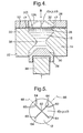
- An apparatus 10 for bulge testing an article 12 is shown in figures 1 to 5 and comprises a fluid filled pressure vessel 14, a gun 16, means 19 to measure deflection of the article 12, means 39 to measure pressure in the pressure vessel 14 and means 18 to determine the material properties of the article 12.
- the pressure vessel 14 has a first end 20, a second end 22, a piston 24 arranged to move within the pressure vessel 14 and a clamping member 26.
- the first end 20 of the pressure vessel 14 has a first aperture 28 and the second end 22 of the pressure vessel 14 has a second aperture 30.
- the clamping member 26 has an aperture 32 and the clamping member 26 is arranged in use such that the aperture 32 in the clamping member 26 is aligned with the first aperture 28 in the first end 20 of the pressure vessel 14 to clamp the article 12 between the first end 20 of the pressure vessel 14 and the clamping member 26 such that the article 12 extends across the first aperture 28 in the first end 20 of the pressure vessel 14 to seal the first end 20 of the pressure vessel 14.
- the piston 24 is arranged to seal the second end 22 of the pressure vessel 14.
- the pressure vessel 14 has a minimum cross-sectional area 38 at a position between the first end 20 and the second end 22.
- the pressure vessel 14 preferably defines a chamber 15, which is circular in cross-section, but the chamber 15 may be triangular, rectangular, square, elliptical or other suitable shapes may be used.
- the first aperture 28 and second aperture 30 in the pressure vessel 14 have the same cross-sectional shape as the chamber 15 in the pressure vessel 14.
- the gun 16 includes a barrel 34 and a projectile 36 is arranged to move within the barrel 34.
- the end of the barrel 34 is secured to the second end 22 of the pressure vessel 14 and the second aperture 30 in the second end 22 of the pressure vessel 14 is aligned with the barrel 34.
- the gun 16 is preferably a gas gun, but the gun 16 may be an electromagnetic gun or a percussive gun or other suitable gun capable of firing the projectile 36 at velocities of up to 40ms -1 .
- the chamber 15 of the pressure vessel 14 contains a liquid, for example the pressure vessel 14 contains an oil.
- the pressure vessel 14 is provided with means 39 to measure the pressure in the pressure vessel 14.
- the means 39 to measure the pressure comprises a high-speed high pressure gauge.
- the means 39 to measure the pressure is arranged to supply signals to a processor 54.
- the gun 16 is provided with means 40 to measure the velocity of the projectile 36 before the projectile 36 impacts with the piston 24.
- the means 40 to measure the velocity of the projectile 36 comprises a plurality of light beams 42 spaced apart along the length of the barrel 34, each light beam 42 extends transversely across the barrel 34.
- the light beams 42 are produced by light sources 44 and the light beams 42 are detected by light detectors 46.
- the light detectors 46 supply signals to the processor 54.
- the breaking of a first light beam 42 starts a clock and the breaking of the second light beam 42 stops the clock and the velocity of the projectile 36 is determined from the time taken to travel between the two light beams 42 and the known distance between the light beams 42, which is calculated in the processor 54.
- the means 19 to measure the deflection of the article 12 comprises at least one high-speed high-resolution camera 48, two mirrors 50 and 52 and the processor 54.
- the high-speed high-resolution camera 48 may be used at rates at or between 11000 and 22000 frames per second.
- the high-speed high-resolution camera 48 uses high-resolution photographic films, which are digitised before image analysis is performed. Each recorded image contains information about the deformation, displacement, of points, dots, on the article 12 as a function of time.
- the two mirrors 50 and 52 are arranged at different angles to produce a stereoscopic view of the article 12, each mirror 50 and 52 respectively is arranged to focus on a portion, half, of the image plane of the camera 48.
- a first mirror 50 is arranged at a predetermined angle and the angle of a second mirror 52 is adjustable.
- the first mirror 50 is arranged at an angle of 45° to the surface of the undeformed article 12.
- the processor 54 is arranged to analyse the stereoscopic view of the article 12 produced by the camera 48 to determine the deflection of the article 12.
- the article 12 for dynamic bulge testing is initially marked with a regular grid, for example a rectangular grid, of dots 60 in order to enable the calculation of surface displacement of the article 12 during the deformation process from the photographic images produced by the high speed high resolution camera 48, see figure 5.
- a regular grid for example a rectangular grid
- the article 12 is placed between the first end 20 of the pressure vessel 14 and the clamping member 26 and the clamping of the article 12 deforms the article 12 near draw beads 17 but leaves the article 12 unaffected within the aperture 28.
- the draw beads 17 are positioned as close as possible to the inner diameter of the pressure vessel 14 to prevent material being drawn into the pressure vessel 14 during loading. Excess oil is forced out of the pressure vessel 14 during deformation of the article 12 along the draw bead 17 allowing the article 12 to seal the pressure vessel 14 without trapping any gas, air.
- the gun 16 In use the gun 16 is fired and the projectile 36 travels along the barrel 34 and strikes the piston 24.
- the piston 24 moves within the pressure vessel 14 and compresses the fluid, oil, in the chamber 15 to produce a high pressure in the fluid in the pressure vessel 14 to rapidly deform the article 12 to the position 12A, as shown in figure 4.
- any data measured during the dynamic bulge testing is recorded in the processor 54 using a computer controlled multi-channel data acquisition system capable of recording data rates of up to 20MSs -1 (Mega-Samples per second). The data acquisition is performed at 500kSs -1 (kilo-Samples per second).
- the total pressure applied in the pressure vessel 14 as a function of time was measured by the means 39 to measure the pressure in the pressure vessel 14 and the surface displacements of the article 12 as a function of time are measured by the high speed high resolution camera 48 using the grid of dots 60 on the article 12.
- the data obtained is in the form of analogue electric signals from the means 39 to measure pressure and analogue images from the camera 48. These signals may be digitised before going to the processor 54 or by the processor 54.
- the pressure signals recorded during the dynamic bulge testing are often masked by high frequency noise, due to electronic noise and pressure waves in the complex geometry of the pressure vessel 14 which interfere.
- the pressure signal is filtered using a FFT (Fast Fourier Transform) in which the pressure signals are converted to their frequency spectrum using FFT after which the high frequencies are subtracted and the pressure signals are converted back using Inverse FFT.
- FFT Fast Fourier Transform
- the images of the article 12 captured by the camera 48 during deformation of the article 12 are analysed as follows.
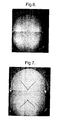
- the analysis starts by considering an "original image” of the undeformed article 12, see figure 6.
- the "local background” is subtracted from the "original image” to leave the desired features, the dots 60.
- the image is also inverted and the range is adjusted to make it suitable for further analysis.
- the image is converted to black and white using a simple threshold procedure, the threshold value is optimally adjusted to give the best results. Then "speckle noise" is removed with a 2 x 2 median filter.
- each feature, dot, 60 is labelled.
- the dots 60 are coloured in different shades for clarity.
- the location, the coordinates, of the polar point 62 in the two images of the article 12 is determined, it is assumed that the polar point 62 is represented by the largest coloured area in each of the two images.
- the location of the polar point 62 in the two images is used to locate the coordinates of the dots 60 in the grid. Some error checking may be used that each dot 60 is not too far from its expected location and that there are no repeated dots 60.
- the dots 60 detected from the first mirror 50 arranged at 45° are centre point superimposed on the original image and the dots 60 detected from the second mirror 52 are superimposed on the original image.
- the obtained results are superimposed over the original images during image analysis to enable simple visual control.
- the image analysis procedure completes with an output of the dot 60 coordinates into suitable files, one file for the entire dot field and one for the principal meridians only.
- the change in coordinates of the marked dots 60 on the surface of the article 12 during dynamic bulge testing provides the necessary information about the deformation of the article 12. This holds the key to determining the strains and combined with the pressure signals provided by the means 18 to measure pressure the key to determining the stress at the polar point 62 of the article 12.
- the polar point 62 is the centre point of the article 12, e.g. is in the centre of the first aperture 28.
- dots 64 marked along primary perpendicular meridians 66 and 68 intersecting the polar point 62 are used, and only 10 dots in each primary meridian 66 and 68 excluding the polar point 62, see figures 5 and 7. It may be possible to use other selections of dots 60.
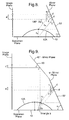
- the angle ⁇ of the second mirror 52 relative to the original surface of the article 12 is determined.
- the angle of the second mirror 52 is obtained by examining the distance "a" between two points on the surface, plane, of the article 12 and the distance "a'" between the corresponding two points on the image plane.
- the altitude, or height, or z coordinate of the polar point 62 is determined.
- the height of the polar point 62 is determined using the second mirror 52.
- the height of the bulge z p is calculated from trigonometric descriptions of triangles 1 and 2 in figure 8.
- the altitude, or height, or z coordinate of the dots 64 along the primary meridians 66 and 68 are determined. This uses combining information from mirrors 50 and 52. At each stage during bulging the position of the dot 64 under consideration is divided into two segments. The first segment Z 1 is calculated using the distance between the corresponding points recorded by the second mirror 52 (a'). The second segment Z 2 is obtained using the distance between the corresponding points recorded using the first mirror 50 (c').
- the processor 54 determines the chord length D, dome segment height h and radius R of the deformed article 12A between two points 64 arranged symmetrically about the pole point 62 of the deformed article.
- the processor 54 determines the thickness t of the deformed article 12A from the chord length D and dome height h of the deformed article 12A.
- the processor 54 determines the stress in the deformed article 12A from the pressure p applied and the original thickness of the article 12 and the radius R of the deformed article 12A.
- the means to measure the material properties of the article comprises two high-speed high resolution cameras arranged to produce a stereoscopic view of the article.
- the camera has been described as a photographic camera it may be possible to use a digital camera in which case the signals supplied by the camera to the processor are digital and not analogue.
- the present invention is able to provide multiracial tensile bulge testing of articles dynamically and enables better material characterisation during development and reduce number of large-scale tests.
- the present invention is applicable to the testing of materials for use in blade containment casings/systems of gas turbine engines and in particular for fan containment casings of turbofan gas turbine engines.
- the article may be an actual article or a specimen.
Landscapes
- Physics & Mathematics (AREA)
- Health & Medical Sciences (AREA)
- Life Sciences & Earth Sciences (AREA)
- Chemical & Material Sciences (AREA)
- Analytical Chemistry (AREA)
- Biochemistry (AREA)
- General Health & Medical Sciences (AREA)
- General Physics & Mathematics (AREA)
- Immunology (AREA)
- Pathology (AREA)
- Electromagnetism (AREA)
- Investigating Strength Of Materials By Application Of Mechanical Stress (AREA)
- Length Measuring Devices By Optical Means (AREA)
- Shaping Metal By Deep-Drawing, Or The Like (AREA)
Abstract
Description
z = z1+z2 = - a'/cos(2ϕ) - c' tan(2ϕ)
Claims (23)
- An apparatus (10) for bulge testing an article (12) comprising a pressure vessel (14) arranged to define a chamber (15), the pressure vessel (14) having a first aperture (28) and a second aperture (30), in use the article (12) being arranged over the first aperture (28) in the pressure vessel (14) to seal the pressure vessel (14), means to pressurise the chamber (15), means (19) to measure the deflection of the article (12), means (39) to measure the pressure in the pressure vessel (14) and means (18) to determine material properties of the article (12) using the measurements of pressure in the pressure vessel (14) and the measurements of deflection of the article (12), characterised in that a piston (24) being arranged to move within the pressure vessel (14), the chamber (15) being filled with a fluid, the means to pressurise the pressure vessel (14) comprising a gun (16) arranged to fire a projectile (36) to strike the piston (24) to produce a high pressure in the fluid in the chamber (15) in the pressure vessel (14) to deform the article (12).
- An apparatus as claimed in claim 1 comprising a clamping member (26) having an aperture (32), the clamping member (26) being arranged in use such that the aperture (32) in the clamping member (26) is aligned with the first aperture (28) in the first end (20) of the pressure vessel (14) to clamp the article (12) between the first end (20) of the pressure vessel (14) and the clamping member (26) such that the article (12) extends across the first aperture (28) in the first end (20) of the pressure vessel (14) to seal the first end (20) of the pressure vessel (14).
- An apparatus as claimed in claim 1 or claim 2 wherein the piston (24) being arranged to seal the second end (30) of the pressure vessel (14).
- An apparatus as claimed in claim 1, claim 2 or claim 3 wherein the gun (16) including a barrel (34) and the projectile (36) being arranged to move within the barrel (34), the end of the barrel (34) being secured to the second end (22) of the pressure vessel (14) and the second aperture (30) in the second end (22) of the pressure vessel (14) being aligned with the barrel (34) such that in use the projectile (36) may strike the piston (24) to produce a high pressure in the fluid in the pressure vessel (14) to deform the article (12).
- An apparatus as claimed in any of claims 1 to 4 wherein the pressure vessel (14) has a minimum cross-sectional area (38) at a position between the first end (20) and the second end (22).
- An apparatus as claimed in any of claims 1 to 5 wherein the gun (16) is a gas gun.
- An apparatus as claimed in any of claims 1 to 6 wherein the pressure vessel (14) contains a liquid.
- An apparatus as claimed in claim 7 wherein the pressure vessel (14) contains an oil.
- An apparatus as claimed in any of claims 1 to 8 wherein the means (39) to measure the pressure comprises a high-speed high pressure gauge.
- An apparatus as claimed in any of claims 1 to 9 wherein there are means (40) to measure the velocity of the projectile (36) before impact with the piston (24).
- An apparatus as claimed in claim 10 wherein the means (40) to measure the velocity comprises a plurality of light beams (42) spaced apart along the length of the barrel (34), each light beam (42) extends transversely across the barrel (34).
- An apparatus as claimed in any of claims 1 to 11 wherein the means (19) to measure the deflection of the article (12) comprises at least one high-speed high-resolution camera (48).
- An apparatus as claimed in claim 12 wherein the means (19) to measure the deflection of the article comprises two high-speed high-resolution cameras (48) arranged to produce a stereoscopic view of the article (12).
- An apparatus as claimed in claim 12 wherein the means (19) to measure the deflection of the article (12) comprises two mirrors (50,52) arranged at different angles relative to the surface of the article (12) to produce a stereoscopic view of the article (12), each mirror (50,52) being arranged to focus on a portion of the image plane of the camera (48).
- An apparatus as claimed in claim 14 wherein a first mirror (50) is arranged at a predetermined angle and the angle of a second mirror (52) is adjustable.
- An apparatus as claimed in claim 15 wherein the first mirror (50) is arranged at an angle of 45°.
- An apparatus as claimed in any of claims 13 to 16 wherein the means (18) to measure the material properties of the article (12) comprises a processor (54) to analyse the stereoscopic view of the article (12).
- An apparatus as claimed in claim 17 wherein the processor (54) has means to determine the angle of the second mirror (52) relative to the undeformed article (12).
- An apparatus as claimed in claim 18 wherein the processor (54) has means to determine the altitude of a polar point (62) on the deformed article (12) relative to the undeformed article (12) from the determined angle of the second mirror (52).
- An apparatus as claimed in claim 19 wherein the processor (54) has means to determine the altitude of other points (64) on the deformed article (12) relative to the undeformed article (12) from the determined angle for the second mirror (52).
- A method of bulge testing an article (12) comprising providing a pressure vessel (14) arranged to define a chamber (15), the pressure vessel (14) having a first aperture (28) and a second aperture (30), the chamber (15) being filled with a fluid, arranging the article (12) over the first aperture (28) in the pressure vessel (14) to seal the pressure vessel (14), a piston (24) being arranged to move within the pressure vessel (14), firing a projectile (36) to strike the piston (24) to produce a high pressure in the fluid in the chamber (15) in the pressure vessel (14) to deform the article (12), measuring the deflection of the article (12), measuring the pressure in the pressure vessel (14) and determining material properties of the article (12) using the measurements of pressure in the pressure vessel (14) and the measurements of deflection of the article (12).
- An apparatus (10) for bulge testing an article (12) comprising a pressure vessel (14) arranged to define a chamber (15), the pressure vessel (14) having a first aperture (28), means to pressurise the chamber (39), means (19) to measure the deflection of the article (12), means (39) to measure the pressure in the pressure vessel (14) and means (18) to determine material properties of the article (12) using the measurements of pressure in the pressure vessel (14) and the measurements of deflection of the article (12), characterised in that the means (19) to measure the deflection of the article (12) comprising two mirrors (50,52) arranged at different angles relative to the surface of the article (12) to produce a stereoscopic view of the article (12), each mirror (50,52) being arranged to focus on a portion of the image plane of a camera (48).
- A method of bulge testing an article (12) comprising providing a pressure vessel (14) arranged to define a chamber (15), the pressure vessel (14) having a first aperture (28), arranging the article (12) over the first aperture (28) in the pressure vessel (14) to seal the pressure vessel (14), pressurising the chamber (15) in the pressure vessel (14) to deform the article (12), measuring the deflection of the article (12), measuring the pressure in the pressure vessel (14) and determining material properties of the article (12) using the measurements of pressure in the pressure vessel (14) and the measurements of deflection of the article (12), wherein the measuring of the deflection of the article (12) comprising providing two mirrors (50,52) arranged at different angles relative to the surface of the article (12) to produce a stereoscopic view of the article (12) and arranging each mirror (50,52) to focus on a portion of the image plane of a camera (48).
Applications Claiming Priority (2)
| Application Number | Priority Date | Filing Date | Title |
|---|---|---|---|
| GB0413650 | 2004-06-18 | ||
| GBGB0413650.3A GB0413650D0 (en) | 2004-06-18 | 2004-06-18 | An apparatus and method for bulge testing an article |
Publications (3)
| Publication Number | Publication Date |
|---|---|
| EP1607731A2 true EP1607731A2 (en) | 2005-12-21 |
| EP1607731A3 EP1607731A3 (en) | 2013-05-15 |
| EP1607731B1 EP1607731B1 (en) | 2015-07-22 |
Family
ID=32750149
Family Applications (1)
| Application Number | Title | Priority Date | Filing Date |
|---|---|---|---|
| EP05253053.2A Ceased EP1607731B1 (en) | 2004-06-18 | 2005-05-18 | Apparatus and method for bulge testing an article |
Country Status (3)
| Country | Link |
|---|---|
| US (2) | US20050279162A1 (en) |
| EP (1) | EP1607731B1 (en) |
| GB (1) | GB0413650D0 (en) |
Cited By (6)
| Publication number | Priority date | Publication date | Assignee | Title |
|---|---|---|---|---|
| CN102175537A (en) * | 2011-01-13 | 2011-09-07 | 北京航空航天大学 | Thermal medium bulging test machine |
| CZ302741B6 (en) * | 2009-09-24 | 2011-10-12 | Vysoká škola bánská-Technická univerzita Ostrava | Device for multiaxial combined loading of test specimens |
| WO2016196397A1 (en) * | 2015-06-04 | 2016-12-08 | Raytheon Company | Hyper-velocity impact sensor |
| CN106290016A (en) * | 2016-10-25 | 2017-01-04 | 安徽理工大学 | A kind of underground air impact disaster assay device |
| CN110104229A (en) * | 2019-05-21 | 2019-08-09 | 哈尔滨工业大学 | For high speed or the pressure-bearing device of hypervelocity impact X-ray shooting panus |
| CN113405756A (en) * | 2021-06-15 | 2021-09-17 | 安徽朗迪叶轮机械有限公司 | Height-adjustable cross-flow fan blade drop test tool |
Families Citing this family (15)
| Publication number | Priority date | Publication date | Assignee | Title |
|---|---|---|---|---|
| US8453515B2 (en) * | 2010-09-03 | 2013-06-04 | UT-BaHelle, LLC | Apparatus and method for fatigue testing of a material specimen in a high-pressure fluid environment |
| DE102011051934A1 (en) * | 2011-07-19 | 2013-01-24 | Wincor Nixdorf International Gmbh | Method and device for OCR acquisition of value documents by means of a matrix camera |
| US8746085B2 (en) * | 2011-09-07 | 2014-06-10 | Cal Poly Corporation | Method and apparatus for measuring container bulge |
| US8770037B2 (en) * | 2011-10-14 | 2014-07-08 | Chrysler Group Llc | System and method for structure stiffness determination |
| US8935963B2 (en) * | 2012-07-30 | 2015-01-20 | The United States Of America As Represented By The Secretary Of The Navy | Gas gun fixture to evaluate blast wave on target sample |
| GB2557065B (en) * | 2015-08-27 | 2021-12-01 | Illinois Tool Works | Field splitter for three-dimensional strain measurement |
| WO2017070054A1 (en) * | 2015-10-19 | 2017-04-27 | DimensionalMechanics, Inc. | System and methods for characterizing a fabric or material |
| FR3048501B1 (en) * | 2016-03-02 | 2020-08-28 | Univ Bretagne Sud | DEVICE FOR IMPLEMENTING A BIAXIAL TENSILE TEST OF A MATERIAL |
| US10634594B2 (en) * | 2016-03-18 | 2020-04-28 | Intel Corporation | Membrane test for mechanical testing of stretchable electronics |
| US10670501B2 (en) | 2016-08-26 | 2020-06-02 | Rasoul Jelokhani Niaraki | Apparatus for universal testing of metal sheet formability |
| CN106404287A (en) * | 2016-09-09 | 2017-02-15 | 青岛海斯兰德新材料有限公司 | Integrated air bag leak detection apparatus |
| US11118705B2 (en) | 2018-08-07 | 2021-09-14 | General Electric Company | Quick connect firewall seal for firewall |
| CN111175141B (en) * | 2020-02-07 | 2021-02-09 | 河海大学 | Method for selecting and matching particle cushion layer with reasonable particle size and free of damage to geomembrane |
| KR102825695B1 (en) * | 2020-06-23 | 2025-06-27 | 주식회사 엘지에너지솔루션 | System and method for testing fatigue of metal foil |
| CN118961378B (en) * | 2024-10-16 | 2024-12-27 | 南通信达通检测有限公司 | A kind of testing equipment and method for building material production |
Family Cites Families (20)
| Publication number | Priority date | Publication date | Assignee | Title |
|---|---|---|---|---|
| US2696105A (en) * | 1952-05-27 | 1954-12-07 | Mackas George | Simulated depth charge shock machine |
| US3074170A (en) * | 1959-10-23 | 1963-01-22 | Jet Res Ct Inc | Method for studying explosions stereoscopically |
| US3109057A (en) * | 1960-12-08 | 1963-10-29 | Singer Inc H R B | Stereo scanning unit and system |
| US3277693A (en) * | 1964-05-14 | 1966-10-11 | Olin Mathieson | Dynamic tester |
| US3729980A (en) * | 1972-03-02 | 1973-05-01 | Us Navy | Hydrodynamic shock simulator |
| DE2833808C3 (en) * | 1978-08-02 | 1982-04-01 | Deutsche Forschungs- und Versuchsanstalt für Luft- und Raumfahrt e.V., 5000 Köln | Stereo line scanner |
| US4483190A (en) * | 1982-09-24 | 1984-11-20 | Fmc Corporation | Muzzle velocimeter |
| US4735092A (en) * | 1986-12-05 | 1988-04-05 | Emk Testing Company, Inc. | Apparatus for rupture testing metal films |
| SU1453231A1 (en) * | 1987-03-24 | 1989-01-23 | Предприятие П/Я М-5671 | Method of testing materials for tqo-axis tension |
| US4905502A (en) * | 1988-02-09 | 1990-03-06 | Mts Systems Corporation | Pressure vessel fatigue test system |
| US5311856A (en) * | 1992-10-20 | 1994-05-17 | The United States Of America As Represented By The Secretary Of The Army | Gas gun and quick release mechanism for large loads |
| EP0849583A1 (en) * | 1996-12-12 | 1998-06-24 | European Community | Split Hopkinson bar testing apparatus |
| US6050138A (en) * | 1997-10-22 | 2000-04-18 | Exponent, Inc. | System and method for performing bulge testing of films, coatings and/or layers |
| EP0971261B1 (en) * | 1998-07-09 | 2004-10-20 | Matsushita Electric Industrial Co., Ltd. | Stereoscopic picture obtaining device |
| US6539790B2 (en) * | 2000-12-04 | 2003-04-01 | University Of Vermont And State Agricultural College | Stiction-based chuck for bulge tester and method of bulge testing |
| JP3857197B2 (en) * | 2002-07-12 | 2006-12-13 | 日本碍子株式会社 | Crack detection method and crack detection apparatus for honeycomb structure |
| FR2845771A1 (en) * | 2002-10-09 | 2004-04-16 | Ncv Ind | Apparatus characterizing vehicle airbag textiles, comprises piston-cylinder arrangement with instrumentation measuring porosity and rupture strength under applied pressures |
| US6769287B2 (en) * | 2002-12-17 | 2004-08-03 | Haag Engineering Co. | Apparatus for testing structural component samples by impacting with ice balls |
| US20040261494A1 (en) * | 2003-06-24 | 2004-12-30 | Lee Kun Ta | Impact generating device for impact tester |
| KR100590450B1 (en) * | 2003-10-29 | 2006-06-19 | 재단법인서울대학교산학협력재단 | Fluff measuring method using three dimensional image and fluff measuring device using same |
-
2004
- 2004-06-18 GB GBGB0413650.3A patent/GB0413650D0/en not_active Ceased
-
2005
- 2005-05-18 EP EP05253053.2A patent/EP1607731B1/en not_active Ceased
- 2005-05-19 US US11/132,245 patent/US20050279162A1/en not_active Abandoned
-
2007
- 2007-03-19 US US11/723,293 patent/US7409848B2/en not_active Expired - Fee Related
Cited By (7)
| Publication number | Priority date | Publication date | Assignee | Title |
|---|---|---|---|---|
| CZ302741B6 (en) * | 2009-09-24 | 2011-10-12 | Vysoká škola bánská-Technická univerzita Ostrava | Device for multiaxial combined loading of test specimens |
| CN102175537A (en) * | 2011-01-13 | 2011-09-07 | 北京航空航天大学 | Thermal medium bulging test machine |
| WO2016196397A1 (en) * | 2015-06-04 | 2016-12-08 | Raytheon Company | Hyper-velocity impact sensor |
| CN106290016A (en) * | 2016-10-25 | 2017-01-04 | 安徽理工大学 | A kind of underground air impact disaster assay device |
| CN106290016B (en) * | 2016-10-25 | 2018-11-20 | 安徽理工大学 | A kind of underground air impact disaster experimental rig |
| CN110104229A (en) * | 2019-05-21 | 2019-08-09 | 哈尔滨工业大学 | For high speed or the pressure-bearing device of hypervelocity impact X-ray shooting panus |
| CN113405756A (en) * | 2021-06-15 | 2021-09-17 | 安徽朗迪叶轮机械有限公司 | Height-adjustable cross-flow fan blade drop test tool |
Also Published As
| Publication number | Publication date |
|---|---|
| US7409848B2 (en) | 2008-08-12 |
| US20070220966A1 (en) | 2007-09-27 |
| EP1607731A3 (en) | 2013-05-15 |
| GB0413650D0 (en) | 2004-07-21 |
| US20050279162A1 (en) | 2005-12-22 |
| EP1607731B1 (en) | 2015-07-22 |
Similar Documents
| Publication | Publication Date | Title |
|---|---|---|
| US7409848B2 (en) | Apparatus and method for bulge testing an article | |
| Calder et al. | Plastic deformation and perforation of thin plates resulting from projectile impact | |
| CN104864819B (en) | A kind of high speed three-dimensional strain measurement method based on digital speckle | |
| Sourgen et al. | Reconstruction of the density field using the colored background oriented schlieren technique (CBOS) | |
| CA2473564A1 (en) | Identification and location of an object via passive acoustic detection | |
| CN204988587U (en) | Pneumatic frictional resistance measuring device of high accuracy non -contact | |
| Schairer et al. | Measurements of unsteady aeroelastic model deformation by stereo photogrammetry | |
| CN109406105B (en) | Virtual image detection method and detection system | |
| Clem et al. | Background oriented schlieren implementation in a jet-surface interaction test | |
| Di Lorenzo et al. | Full-field modal analysis using high-speed 3D digital image correlation | |
| Fisher et al. | An experimental sensitivity comparison of the schlieren and background-oriented schlieren techniques applied to hypersonic flow | |
| Leopold | The application of the colored background oriented schlieren technique (CBOS) to free-flight and in-flight measurements | |
| Neri | Frequency-band down-sampled stereo-DIC: Beyond the limitation of single frequency excitation | |
| Kikkawa et al. | Three-dimensional measurement of local strain using digital stereo photogrammetry in the triaxial test | |
| Ma et al. | NIST bullet signature measurement system for RM (Reference Material) 8240 standard bullets | |
| Wu et al. | Optical sensor developments for measuring the surface strains in prestressed concrete members | |
| Mizukaki | Visualization of compressible vortex rings using the background-oriented schlieren method | |
| CN112326470B (en) | Method for measuring dynamic deformation of cylindrical composite material under explosion impact effect | |
| Helfrick | An investigation of 3D digital image correlation for structural health monitoring and vibration measurement | |
| Ukai et al. | Validation of measurement accuracy for near-field pressure around supersonic projectiles in a ballistic range | |
| Raghunath et al. | Visualization of supersonic flows in shock tunnels, using the background oriented schlieren technique | |
| Hird et al. | Study of unsteady surface pressure on a turret via pressure-sensitive paint | |
| Mizukaki et al. | Four-dimensional visualization of blast loading inside a detonation-driven shock tube using improved pressure-sensitive paint and digital image correlation | |
| Ota et al. | Improvements of spatial resolution of colored-grid background oriented schlieren (CGBOS) technique by introducing tele centric optical system and reconstruction of density field | |
| Breen | Source Location of Subsonic and Supersonic Jets of Various Geometeries Via Acoustic Beamforming |
Legal Events
| Date | Code | Title | Description |
|---|---|---|---|
| PUAI | Public reference made under article 153(3) epc to a published international application that has entered the european phase |
Free format text: ORIGINAL CODE: 0009012 |
|
| AK | Designated contracting states |
Kind code of ref document: A2 Designated state(s): AT BE BG CH CY CZ DE DK EE ES FI FR GB GR HU IE IS IT LI LT LU MC NL PL PT RO SE SI SK TR |
|
| AX | Request for extension of the european patent |
Extension state: AL BA HR LV MK YU |
|
| PUAL | Search report despatched |
Free format text: ORIGINAL CODE: 0009013 |
|
| AK | Designated contracting states |
Kind code of ref document: A3 Designated state(s): AT BE BG CH CY CZ DE DK EE ES FI FR GB GR HU IE IS IT LI LT LU MC NL PL PT RO SE SI SK TR |
|
| AX | Request for extension of the european patent |
Extension state: AL BA HR LV MK YU |
|
| RIC1 | Information provided on ipc code assigned before grant |
Ipc: G01N 3/317 20060101ALI20130408BHEP Ipc: G01N 3/313 20060101ALI20130408BHEP Ipc: G01N 3/00 20060101AFI20130408BHEP Ipc: G01N 3/12 20060101ALI20130408BHEP Ipc: G01N 3/307 20060101ALI20130408BHEP |
|
| 17P | Request for examination filed |
Effective date: 20131115 |
|
| RBV | Designated contracting states (corrected) |
Designated state(s): AT BE BG CH CY CZ DE DK EE ES FI FR GB GR HU IE IS IT LI LT LU MC NL PL PT RO SE SI SK TR |
|
| AKX | Designation fees paid |
Designated state(s): DE FR GB |
|
| 17Q | First examination report despatched |
Effective date: 20140424 |
|
| GRAP | Despatch of communication of intention to grant a patent |
Free format text: ORIGINAL CODE: EPIDOSNIGR1 |
|
| INTG | Intention to grant announced |
Effective date: 20150504 |
|
| GRAS | Grant fee paid |
Free format text: ORIGINAL CODE: EPIDOSNIGR3 |
|
| GRAA | (expected) grant |
Free format text: ORIGINAL CODE: 0009210 |
|
| AK | Designated contracting states |
Kind code of ref document: B1 Designated state(s): DE FR GB |
|
| REG | Reference to a national code |
Ref country code: GB Ref legal event code: FG4D |
|
| RAP2 | Party data changed (patent owner data changed or rights of a patent transferred) |
Owner name: ROLLS-ROYCE PLC |
|
| REG | Reference to a national code |
Ref country code: DE Ref legal event code: R096 Ref document number: 602005047017 Country of ref document: DE |
|
| REG | Reference to a national code |
Ref country code: DE Ref legal event code: R097 Ref document number: 602005047017 Country of ref document: DE |
|
| PLBE | No opposition filed within time limit |
Free format text: ORIGINAL CODE: 0009261 |
|
| STAA | Information on the status of an ep patent application or granted ep patent |
Free format text: STATUS: NO OPPOSITION FILED WITHIN TIME LIMIT |
|
| REG | Reference to a national code |
Ref country code: DE Ref legal event code: R082 Ref document number: 602005047017 Country of ref document: DE Representative=s name: HERNANDEZ, YORCK, DIPL.-ING., DE |
|
| REG | Reference to a national code |
Ref country code: FR Ref legal event code: PLFP Year of fee payment: 12 |
|
| 26N | No opposition filed |
Effective date: 20160425 |
|
| REG | Reference to a national code |
Ref country code: FR Ref legal event code: PLFP Year of fee payment: 13 |
|
| REG | Reference to a national code |
Ref country code: FR Ref legal event code: PLFP Year of fee payment: 14 |
|
| PGFP | Annual fee paid to national office [announced via postgrant information from national office to epo] |
Ref country code: FR Payment date: 20200527 Year of fee payment: 16 |
|
| PGFP | Annual fee paid to national office [announced via postgrant information from national office to epo] |
Ref country code: GB Payment date: 20200528 Year of fee payment: 16 |
|
| PGFP | Annual fee paid to national office [announced via postgrant information from national office to epo] |
Ref country code: DE Payment date: 20200728 Year of fee payment: 16 |
|
| REG | Reference to a national code |
Ref country code: DE Ref legal event code: R119 Ref document number: 602005047017 Country of ref document: DE |
|
| GBPC | Gb: european patent ceased through non-payment of renewal fee |
Effective date: 20210518 |
|
| PG25 | Lapsed in a contracting state [announced via postgrant information from national office to epo] |
Ref country code: GB Free format text: LAPSE BECAUSE OF NON-PAYMENT OF DUE FEES Effective date: 20210518 Ref country code: DE Free format text: LAPSE BECAUSE OF NON-PAYMENT OF DUE FEES Effective date: 20211201 |
|
| PG25 | Lapsed in a contracting state [announced via postgrant information from national office to epo] |
Ref country code: FR Free format text: LAPSE BECAUSE OF NON-PAYMENT OF DUE FEES Effective date: 20210531 |