EP1607679A2 - LED lamp and lamp reflector assembly - Google Patents
LED lamp and lamp reflector assembly Download PDFInfo
- Publication number
- EP1607679A2 EP1607679A2 EP05012719A EP05012719A EP1607679A2 EP 1607679 A2 EP1607679 A2 EP 1607679A2 EP 05012719 A EP05012719 A EP 05012719A EP 05012719 A EP05012719 A EP 05012719A EP 1607679 A2 EP1607679 A2 EP 1607679A2
- Authority
- EP
- European Patent Office
- Prior art keywords
- frusto
- cover
- led
- conical center
- reflector
- Prior art date
- Legal status (The legal status is an assumption and is not a legal conclusion. Google has not performed a legal analysis and makes no representation as to the accuracy of the status listed.)
- Granted
Links
Images


Classifications
-
- F—MECHANICAL ENGINEERING; LIGHTING; HEATING; WEAPONS; BLASTING
- F21—LIGHTING
- F21S—NON-PORTABLE LIGHTING DEVICES; SYSTEMS THEREOF; VEHICLE LIGHTING DEVICES SPECIALLY ADAPTED FOR VEHICLE EXTERIORS
- F21S41/00—Illuminating devices specially adapted for vehicle exteriors, e.g. headlamps
- F21S41/10—Illuminating devices specially adapted for vehicle exteriors, e.g. headlamps characterised by the light source
- F21S41/14—Illuminating devices specially adapted for vehicle exteriors, e.g. headlamps characterised by the light source characterised by the type of light source
- F21S41/141—Light emitting diodes [LED]
- F21S41/147—Light emitting diodes [LED] the main emission direction of the LED being angled to the optical axis of the illuminating device
-
- F—MECHANICAL ENGINEERING; LIGHTING; HEATING; WEAPONS; BLASTING
- F21—LIGHTING
- F21K—NON-ELECTRIC LIGHT SOURCES USING LUMINESCENCE; LIGHT SOURCES USING ELECTROCHEMILUMINESCENCE; LIGHT SOURCES USING CHARGES OF COMBUSTIBLE MATERIAL; LIGHT SOURCES USING SEMICONDUCTOR DEVICES AS LIGHT-GENERATING ELEMENTS; LIGHT SOURCES NOT OTHERWISE PROVIDED FOR
- F21K9/00—Light sources using semiconductor devices as light-generating elements, e.g. using light-emitting diodes [LED] or lasers
-
- F—MECHANICAL ENGINEERING; LIGHTING; HEATING; WEAPONS; BLASTING
- F21—LIGHTING
- F21S—NON-PORTABLE LIGHTING DEVICES; SYSTEMS THEREOF; VEHICLE LIGHTING DEVICES SPECIALLY ADAPTED FOR VEHICLE EXTERIORS
- F21S41/00—Illuminating devices specially adapted for vehicle exteriors, e.g. headlamps
- F21S41/10—Illuminating devices specially adapted for vehicle exteriors, e.g. headlamps characterised by the light source
- F21S41/14—Illuminating devices specially adapted for vehicle exteriors, e.g. headlamps characterised by the light source characterised by the type of light source
- F21S41/141—Light emitting diodes [LED]
- F21S41/147—Light emitting diodes [LED] the main emission direction of the LED being angled to the optical axis of the illuminating device
- F21S41/148—Light emitting diodes [LED] the main emission direction of the LED being angled to the optical axis of the illuminating device the main emission direction of the LED being perpendicular to the optical axis
-
- F—MECHANICAL ENGINEERING; LIGHTING; HEATING; WEAPONS; BLASTING
- F21—LIGHTING
- F21S—NON-PORTABLE LIGHTING DEVICES; SYSTEMS THEREOF; VEHICLE LIGHTING DEVICES SPECIALLY ADAPTED FOR VEHICLE EXTERIORS
- F21S41/00—Illuminating devices specially adapted for vehicle exteriors, e.g. headlamps
- F21S41/30—Illuminating devices specially adapted for vehicle exteriors, e.g. headlamps characterised by reflectors
- F21S41/32—Optical layout thereof
-
- F—MECHANICAL ENGINEERING; LIGHTING; HEATING; WEAPONS; BLASTING
- F21—LIGHTING
- F21S—NON-PORTABLE LIGHTING DEVICES; SYSTEMS THEREOF; VEHICLE LIGHTING DEVICES SPECIALLY ADAPTED FOR VEHICLE EXTERIORS
- F21S43/00—Signalling devices specially adapted for vehicle exteriors, e.g. brake lamps, direction indicator lights or reversing lights
- F21S43/10—Signalling devices specially adapted for vehicle exteriors, e.g. brake lamps, direction indicator lights or reversing lights characterised by the light source
- F21S43/13—Signalling devices specially adapted for vehicle exteriors, e.g. brake lamps, direction indicator lights or reversing lights characterised by the light source characterised by the type of light source
- F21S43/14—Light emitting diodes [LED]
-
- F—MECHANICAL ENGINEERING; LIGHTING; HEATING; WEAPONS; BLASTING
- F21—LIGHTING
- F21S—NON-PORTABLE LIGHTING DEVICES; SYSTEMS THEREOF; VEHICLE LIGHTING DEVICES SPECIALLY ADAPTED FOR VEHICLE EXTERIORS
- F21S43/00—Signalling devices specially adapted for vehicle exteriors, e.g. brake lamps, direction indicator lights or reversing lights
- F21S43/30—Signalling devices specially adapted for vehicle exteriors, e.g. brake lamps, direction indicator lights or reversing lights characterised by reflectors
- F21S43/31—Optical layout thereof
-
- F—MECHANICAL ENGINEERING; LIGHTING; HEATING; WEAPONS; BLASTING
- F21—LIGHTING
- F21S—NON-PORTABLE LIGHTING DEVICES; SYSTEMS THEREOF; VEHICLE LIGHTING DEVICES SPECIALLY ADAPTED FOR VEHICLE EXTERIORS
- F21S45/00—Arrangements within vehicle lighting devices specially adapted for vehicle exteriors, for purposes other than emission or distribution of light
- F21S45/40—Cooling of lighting devices
- F21S45/47—Passive cooling, e.g. using fins, thermal conductive elements or openings
-
- F—MECHANICAL ENGINEERING; LIGHTING; HEATING; WEAPONS; BLASTING
- F21—LIGHTING
- F21V—FUNCTIONAL FEATURES OR DETAILS OF LIGHTING DEVICES OR SYSTEMS THEREOF; STRUCTURAL COMBINATIONS OF LIGHTING DEVICES WITH OTHER ARTICLES, NOT OTHERWISE PROVIDED FOR
- F21V17/00—Fastening of component parts of lighting devices, e.g. shades, globes, refractors, reflectors, filters, screens, grids or protective cages
- F21V17/10—Fastening of component parts of lighting devices, e.g. shades, globes, refractors, reflectors, filters, screens, grids or protective cages characterised by specific fastening means or way of fastening
- F21V17/101—Fastening of component parts of lighting devices, e.g. shades, globes, refractors, reflectors, filters, screens, grids or protective cages characterised by specific fastening means or way of fastening permanently, e.g. welding, gluing or riveting
-
- F—MECHANICAL ENGINEERING; LIGHTING; HEATING; WEAPONS; BLASTING
- F21—LIGHTING
- F21V—FUNCTIONAL FEATURES OR DETAILS OF LIGHTING DEVICES OR SYSTEMS THEREOF; STRUCTURAL COMBINATIONS OF LIGHTING DEVICES WITH OTHER ARTICLES, NOT OTHERWISE PROVIDED FOR
- F21V29/00—Protecting lighting devices from thermal damage; Cooling or heating arrangements specially adapted for lighting devices or systems
- F21V29/50—Cooling arrangements
- F21V29/70—Cooling arrangements characterised by passive heat-dissipating elements, e.g. heat-sinks
- F21V29/74—Cooling arrangements characterised by passive heat-dissipating elements, e.g. heat-sinks with fins or blades
-
- F—MECHANICAL ENGINEERING; LIGHTING; HEATING; WEAPONS; BLASTING
- F21—LIGHTING
- F21V—FUNCTIONAL FEATURES OR DETAILS OF LIGHTING DEVICES OR SYSTEMS THEREOF; STRUCTURAL COMBINATIONS OF LIGHTING DEVICES WITH OTHER ARTICLES, NOT OTHERWISE PROVIDED FOR
- F21V29/00—Protecting lighting devices from thermal damage; Cooling or heating arrangements specially adapted for lighting devices or systems
- F21V29/50—Cooling arrangements
- F21V29/70—Cooling arrangements characterised by passive heat-dissipating elements, e.g. heat-sinks
- F21V29/74—Cooling arrangements characterised by passive heat-dissipating elements, e.g. heat-sinks with fins or blades
- F21V29/76—Cooling arrangements characterised by passive heat-dissipating elements, e.g. heat-sinks with fins or blades with essentially identical parallel planar fins or blades, e.g. with comb-like cross-section
- F21V29/767—Cooling arrangements characterised by passive heat-dissipating elements, e.g. heat-sinks with fins or blades with essentially identical parallel planar fins or blades, e.g. with comb-like cross-section the planes containing the fins or blades having directions perpendicular to the light emitting axis
-
- F—MECHANICAL ENGINEERING; LIGHTING; HEATING; WEAPONS; BLASTING
- F21—LIGHTING
- F21V—FUNCTIONAL FEATURES OR DETAILS OF LIGHTING DEVICES OR SYSTEMS THEREOF; STRUCTURAL COMBINATIONS OF LIGHTING DEVICES WITH OTHER ARTICLES, NOT OTHERWISE PROVIDED FOR
- F21V29/00—Protecting lighting devices from thermal damage; Cooling or heating arrangements specially adapted for lighting devices or systems
- F21V29/50—Cooling arrangements
- F21V29/70—Cooling arrangements characterised by passive heat-dissipating elements, e.g. heat-sinks
- F21V29/83—Cooling arrangements characterised by passive heat-dissipating elements, e.g. heat-sinks the elements having apertures, ducts or channels, e.g. heat radiation holes
-
- F—MECHANICAL ENGINEERING; LIGHTING; HEATING; WEAPONS; BLASTING
- F21—LIGHTING
- F21V—FUNCTIONAL FEATURES OR DETAILS OF LIGHTING DEVICES OR SYSTEMS THEREOF; STRUCTURAL COMBINATIONS OF LIGHTING DEVICES WITH OTHER ARTICLES, NOT OTHERWISE PROVIDED FOR
- F21V29/00—Protecting lighting devices from thermal damage; Cooling or heating arrangements specially adapted for lighting devices or systems
- F21V29/85—Protecting lighting devices from thermal damage; Cooling or heating arrangements specially adapted for lighting devices or systems characterised by the material
- F21V29/89—Metals
-
- F—MECHANICAL ENGINEERING; LIGHTING; HEATING; WEAPONS; BLASTING
- F21—LIGHTING
- F21S—NON-PORTABLE LIGHTING DEVICES; SYSTEMS THEREOF; VEHICLE LIGHTING DEVICES SPECIALLY ADAPTED FOR VEHICLE EXTERIORS
- F21S45/00—Arrangements within vehicle lighting devices specially adapted for vehicle exteriors, for purposes other than emission or distribution of light
- F21S45/50—Waterproofing
-
- F—MECHANICAL ENGINEERING; LIGHTING; HEATING; WEAPONS; BLASTING
- F21—LIGHTING
- F21W—INDEXING SCHEME ASSOCIATED WITH SUBCLASSES F21K, F21L, F21S and F21V, RELATING TO USES OR APPLICATIONS OF LIGHTING DEVICES OR SYSTEMS
- F21W2107/00—Use or application of lighting devices on or in particular types of vehicles
- F21W2107/10—Use or application of lighting devices on or in particular types of vehicles for land vehicles
-
- F—MECHANICAL ENGINEERING; LIGHTING; HEATING; WEAPONS; BLASTING
- F21—LIGHTING
- F21Y—INDEXING SCHEME ASSOCIATED WITH SUBCLASSES F21K, F21L, F21S and F21V, RELATING TO THE FORM OR THE KIND OF THE LIGHT SOURCES OR OF THE COLOUR OF THE LIGHT EMITTED
- F21Y2115/00—Light-generating elements of semiconductor light sources
- F21Y2115/10—Light-emitting diodes [LED]
Definitions
- This invention relates to electric lamps and particularly to electric lamps with light emitting diode (hereafter LED or LEDs) light sources. More particularly the invention is concerned with an electric lamp with an LED light source coupled to a heat sink with rapid mounting features
- LEDs have been replaced by LEDs.
- These solid-state light sources have enormous life times, in the area of 100,000 hours, and are not as subject to vibration failures.
- these LED sources have been hard-wired into their appropriate location, which increases the cost of installation.
- the light sources have employed multiple LEDs, which increased the cost. It would therefore be an advance in the art if an LED light source could be provided that had the ease of installation of the incandescent light sources. It would be a still further advance in the art if an LED light source could be provided that achieved an industry accepted interchangeable standard to replace the aforementioned incandescent bulb and that used only a single LED. Alternatively, it would be advantageous to have a light source that could be permanently mounted without the need for any specific orientation.
- an LED lamp comprising a substantially concave heat sink having a raised, frusto-conical center surrounded by an outer rim.
- a side-emitting LED is mounted on the frusto-conical center.
- a circumferential planar area is provided between the frusto-conical center and the outer rim and has an outer surface and an inner surface.
- a cover is fixed to the outer surface in a manner to define a volume between the frusto-conical center and the cover.
- a printed circuit board is located in the volume and it has an electrical connection to the LED. At least one electrical contact is positioned in the cover for carrying electrical charges to the printed circuit board.
- An alternate embodiment utilizes studs and barbs for a permanent mounting.
- This LED lamp forms a complete package that is easily installed in a suitable reflector already existing in an automobile and can be compatible with the previously used incandescent sources.
- FIG. 1 there is shown an LED lamp 10 having a substantially concave heat sink 12 having a raised, frusto-conical center 14 surrounded by an outer rim 16.
- the heat sink 12 is preferably formed of aluminum or other metal and at least the frusto-conical center preferably has a reflective coating thereon for reasons that will become apparent hereafter.
- the outer rim 16 can be provided with a plurality of apertures 16a.
- a side-emitting LED 18 is mounted on the frusto-conical center 14.
- the side-emitting LED will have a 60-degree spread +/- 30 degrees from the perpendicular to an axis 19 (see Fig. 2).
- a circumferential planar area 20 is formed between the frusto-conical center 14 and the outer rim 16 and has an outer surface 22 and an inner surface 24.
- a cover 26 is fixed to the outer surface 22 in a manner to define a volume 28 between the frusto-conical center 14 and the cover 26, as shown most clearly n Fig. 2.
- the cover 26 has a circumferential flange 36 and the flange 36 is fixed to the outer surface 22 by a double-sided tape 38.
- This manner of mounting has several advantages in that it is easy and convenient and also helps to form an environmental seal to keep out dirt and moisture; however, other mounting means such as threads, bayonet arms, screws, rivets or other latching means can also be employed, one of which will be described hereinafter.
- a printed circuit board 30 is located within the volume 28 and has the usual electrical traces thereon (not shown) and an electrical connection 32 provides electrical connection to the LED 18.
- cover 26 is provided with an upstanding annular wall 26a and the printed circuit board 30 fits within this wall, making for a secure mounting. At least one electrical contact 34 in cover 26 provides for carrying electrical charges to the printed circuit board 30. In Fig. 2 three such electrical contacts are shown.
- an LED light source 40 for a vehicle that comprises a substantially concave reflector 42 having an aperture 44 in its bottom.
- the LED lamp 10 described above is fitted to the reflector 42 by positioning a second doubled-sided tape 46 between the inner surface 24 of the circumferential planar area 20 and the reflector 42.
- a second doubled-sided tape 46 is provided between the inner surface 24 of the circumferential planar area 20 and the reflector 42.
- an annular flat surface 48 is provided on the reflector 42 to accommodate the tape 46.
- other mounting systems can be employed such as the cammed ears used on many automobiles today, or other threaded structures, or screws, rivets or bayonet arms or other mounts that will be apparent to those skilled in the art.
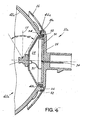
- an LED lamp 10a and an LED light source 40a are shown in Figs. 3 and 4, respectively.
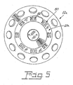
- the light source 40a includes an LED lamp 10a that has a heat sink 12a (shown in Fig. 5), with a circumferential planar area 20a provided with a plurality of stud-receiving barbs 50.
- the barbs 50 have prongs 52 that engage studs 54 formed on flange 36a of a cover 26b and studs 56 formed on an annular flat surface 48a of a reflector 42a.
- Double-sided tapes 38a and 46a are used as previously described; however, the tapes 38a and 46a are provided with stud-receiving apertures 39 and 47, respectively.
- stud-receiving barbs 50 can vary, in a preferred embodiment there are eight such barbs positioned about the circumferential planar area 20a, and the flange 36a and the annular flat surface 48a are provided with four studs each. When assembled, the studs 54 alternate with the studs 56 around the periphery.
- This arrangement insures a very secure, permanent mounting and the double-sided tapes continue to provide a good environmental seal to keep out dirt and moisture. Alignment problems are substantially reduced since the LED light source 40a is symmetrical about the X axis, the Y axis and the Z axis.
- the heat sinks 12 and 12a are spaced away from reflectors 42 and 42a so that air may circulate freely and aid in the necessary cooling.
- the heat sinks 12 and 12a were made from a deep drawn aluminum sheet, the front side of which was aluminized.
- the heat sinks 12 and 12a had an outside diameter of 65 millimeters, while the inner platform section had a diameter of 33 millimeters.
- the axial extension from the middle of the LED 18 to the forward mount of the first seal was 12.2 millimeters, and the axial extension from the same front side of the first seal to the rearmost part of the socket was 19.8 millimeters.
- the side emitting LED 18 had a 60-degree spread +/- 30 degrees from the perpendicular to an axis 19.
- the heat sinks 12 and 12a had a thickness of 0.75 millimeters and had twelve holes 16a evenly spread around the exterior radial extension or rim 16.
Landscapes
- Engineering & Computer Science (AREA)
- General Engineering & Computer Science (AREA)
- Physics & Mathematics (AREA)
- Microelectronics & Electronic Packaging (AREA)
- Optics & Photonics (AREA)
- Arrangement Of Elements, Cooling, Sealing, Or The Like Of Lighting Devices (AREA)
- Non-Portable Lighting Devices Or Systems Thereof (AREA)
- Fastening Of Light Sources Or Lamp Holders (AREA)
- Push-Button Switches (AREA)
- Planar Illumination Modules (AREA)
Abstract
Description
Claims (12)
- An LED lamp comprising:a substantially concave heat sink having a raised, frusto-conical center surrounded by an outer rim;a side-emitting LED mounted on said frusto-conical center;a circumferential planar area between said frusto-conical center and said outer rim, said circumferential planar area having an outer surface and an inner surface;a cover fixed to said outer surface in a manner to define a volume between said frusto-conical center and said cover;a printed circuit board located in said volume having electrical connection to said LED; andat least one electrical contact in said cover for carrying electrical charges to said printed circuit board.
- The LED lamp of Claim 1 wherein said concave heat sink is metal.
- The LED lamp of Claim 2 wherein said metal is aluminum.
- The LED lamp of Claim 1 wherein said cover includes a circumferential flange and said flange is fixed to said outer surface.
- The LED lamp of Claim 4 wherein said flange is fixed to said outer surface by a double-sided tape.
- An LED light source for a vehicle comprising:a substantially concave reflector having an aperture in its bottom;an LED lamp having a substantially concave heat sink having a raised, frusto-conical center surrounded by an outer rim, said frusto-conical center being positioned within said aperture and being fixed to said reflector;a side-emitting LED mounted on said frusto-conical center;a circumferential planar area between said frusto-conical center and said outer rim having an outer surface and an inner surface;a cover fixed to said outer surface in a manner to defme a volume between said frusto-conical center and said cover;a printed circuit board located in said volume having electrical connection to said LED; andat least one electrical contact in said cover for carrying electrical charges to said printed circuit board.
- The LED light source of Claim 6 wherein said LED lamp is fixed to said reflector by a double-sided tape positioned between said inner surface of said circumferential planar area and said reflector.
- The LED light source of Claim 7 wherein said cover includes a flange and said flange is fixed to said outer surface.
- The LED light source of Claim 8 wherein said flange is fixed to said outer surface by a double-sided tape.
- An LED light source for a vehicle comprising:a substantially concave reflector having an aperture in its bottom with an annular flat surface surrounding said aperture;a plurality of reflector studs on said annular flat surface projecting rearward away from said reflector;an LED lamp having a substantially concave heat sink with a raised, frusto-conical center surrounded by an outer rim, said frusto-conical center being positioned within said aperture;a side-emitting LED mounted on said frusto-conical center;a circumferential planar area between said frusto-conical center and said outer rim, said circumferential planar area having an outer surface and an inner surface;a plurality of barbs formed in said circumferential planar area;a cover fixed to said outer surface in a manner to define a volume between said frusto-conical center and said cover, said cover having a circumferential flange having a plurality of cover studs projecting forwardly toward said reflector;a printed circuit board located in said volume having electrical connection to said LED; andat least one electrical contact in said cover for carrying electrical charges to said printed circuit board;said reflector studs and said cover studs being engaged in said plurality of barbs formed in said circumferential planar area.
- The LED light source of Claim 10 wherein said LED lamp has a double-sided tape positioned between said inner surface of said circumferential planar area and said reflector.
- The LED light source of Claim 11 wherein said LED lamp has a double-sided tape between said cover flange and said outer surface.
Applications Claiming Priority (4)
| Application Number | Priority Date | Filing Date | Title |
|---|---|---|---|
| US58006304P | 2004-06-16 | 2004-06-16 | |
| US580063P | 2004-06-16 | ||
| US939582 | 2004-09-13 | ||
| US10/939,582 US7186010B2 (en) | 2004-06-16 | 2004-09-13 | LED lamp and lamp/reflector assembly |
Publications (3)
| Publication Number | Publication Date |
|---|---|
| EP1607679A2 true EP1607679A2 (en) | 2005-12-21 |
| EP1607679A3 EP1607679A3 (en) | 2006-08-02 |
| EP1607679B1 EP1607679B1 (en) | 2009-04-01 |
Family
ID=34937421
Family Applications (1)
| Application Number | Title | Priority Date | Filing Date |
|---|---|---|---|
| EP05012719A Expired - Lifetime EP1607679B1 (en) | 2004-06-16 | 2005-06-14 | LED lamp and lamp reflector assembly |
Country Status (7)
| Country | Link |
|---|---|
| US (1) | US7186010B2 (en) |
| EP (1) | EP1607679B1 (en) |
| JP (1) | JP4856901B2 (en) |
| KR (1) | KR20060047188A (en) |
| AT (1) | ATE427455T1 (en) |
| CA (1) | CA2490590C (en) |
| DE (1) | DE602005013605D1 (en) |
Cited By (8)
| Publication number | Priority date | Publication date | Assignee | Title |
|---|---|---|---|---|
| WO2007135579A1 (en) * | 2006-05-23 | 2007-11-29 | Philips Intellectual Property & Standards Gmbh | Automotive lamp module and lighting unit with led lighting element |
| CN102168933A (en) * | 2011-03-25 | 2011-08-31 | 广州光为照明科技有限公司 | Coupled type matching structure of aluminum substrate and heat radiating piece |
| DE102010014128A1 (en) * | 2010-04-07 | 2011-10-13 | Vivid Chi Matter And Light Gmbh | Pendulum light, has carrying bridge adapted to entire or part of surface configuration of local curvature or bevel of lamp screen, so that planar expansion and positive contact are provided between bridge and lamp screen |
| CN102338311A (en) * | 2011-08-06 | 2012-02-01 | 杨进 | LED (light-emitting diode) lamp |
| US20120268953A1 (en) * | 2009-12-04 | 2012-10-25 | Osram Ag | Lighting Device and Method for Assembling a Lighting Device |
| WO2013117546A1 (en) * | 2012-02-09 | 2013-08-15 | Osram Gmbh | Heat dissipating device, and illuminating device |
| CN103591510A (en) * | 2013-11-12 | 2014-02-19 | 宁波贝克照明电器有限公司 | Novel wall lamp with induction function |
| DE102007040861B4 (en) * | 2006-09-08 | 2014-09-18 | Intel Mobile Communications GmbH | Amplifier arrangement and method for amplifying a signal |
Families Citing this family (51)
| Publication number | Priority date | Publication date | Assignee | Title |
|---|---|---|---|---|
| KR101201307B1 (en) * | 2005-06-30 | 2012-11-14 | 엘지디스플레이 주식회사 | Back Light Unit |
| US7597453B2 (en) * | 2004-01-14 | 2009-10-06 | Simon Jerome H | Luminaires using multiple quasi-point sources for unified radially distributed illumination |
| USD586751S1 (en) * | 2004-04-22 | 2009-02-17 | Osram Sylvania, Inc. | Light emitting diode bulb connector |
| USD619964S1 (en) * | 2004-04-22 | 2010-07-20 | Osram Sylvania, Inc. | Light emitting diode bulb connector |
| USD610544S1 (en) * | 2004-04-22 | 2010-02-23 | Osram Sylvania, Inc. | Light emitting diode bulb connector |
| US7414546B2 (en) * | 2004-07-08 | 2008-08-19 | Honeywell International Inc. | White anti-collision light utilizing light-emitting diode (LED) technology |
| WO2008011723A2 (en) * | 2006-07-28 | 2008-01-31 | Tir Technology Lp | Illumination module with similar heat and light propagation directions |
| DE112006004068A5 (en) * | 2006-10-25 | 2009-07-09 | Osram Gesellschaft mit beschränkter Haftung | lighting device |
| US7510400B2 (en) * | 2007-03-14 | 2009-03-31 | Visteon Global Technologies, Inc. | LED interconnect spring clip assembly |
| US7618163B2 (en) | 2007-04-02 | 2009-11-17 | Ruud Lighting, Inc. | Light-directing LED apparatus |
| KR20090001140A (en) * | 2007-06-29 | 2009-01-08 | 화우테크놀러지 주식회사 | Fanless heat dissipation LED lighting fixtures |
| TWI323329B (en) * | 2007-06-13 | 2010-04-11 | Ama Precision Inc | Led lighting system |
| CN201228949Y (en) * | 2007-07-18 | 2009-04-29 | 胡凯 | LED lamp heat radiation body |
| US7621752B2 (en) * | 2007-07-17 | 2009-11-24 | Visteon Global Technologies, Inc. | LED interconnection integrated connector holder package |
| US7967477B2 (en) * | 2007-09-06 | 2011-06-28 | Philips Lumileds Lighting Company Llc | Compact optical system and lenses for producing uniform collimated light |
| US7736035B2 (en) * | 2008-02-13 | 2010-06-15 | Visteon Global Technologies, Inc. | Seven inch round LED headlamp |
| US20090207617A1 (en) * | 2008-02-20 | 2009-08-20 | Merchant Viren B | Light emitting diode (led) connector clip |
| US8348475B2 (en) * | 2008-05-23 | 2013-01-08 | Ruud Lighting, Inc. | Lens with controlled backlight management |
| US8388193B2 (en) | 2008-05-23 | 2013-03-05 | Ruud Lighting, Inc. | Lens with TIR for off-axial light distribution |
| US9423096B2 (en) | 2008-05-23 | 2016-08-23 | Cree, Inc. | LED lighting apparatus |
| CN201270244Y (en) | 2008-06-27 | 2009-07-08 | 深圳市众明半导体照明有限公司 | Lamp holder |
| US7841750B2 (en) | 2008-08-01 | 2010-11-30 | Ruud Lighting, Inc. | Light-directing lensing member with improved angled light distribution |
| TWI397652B (en) * | 2008-09-05 | 2013-06-01 | Foxconn Tech Co Ltd | Led lamp |
| AU2012216275B9 (en) * | 2008-09-23 | 2013-07-25 | Lsi Industries, Inc. | Lighting apparatus with heat dissipation system |
| US8215799B2 (en) * | 2008-09-23 | 2012-07-10 | Lsi Industries, Inc. | Lighting apparatus with heat dissipation system |
| CN102282412B (en) * | 2009-01-20 | 2014-05-14 | 松下电器产业株式会社 | Illuminating apparatus |
| US20100195306A1 (en) * | 2009-02-03 | 2010-08-05 | Rene Helbing | Light emitting diode lamp with phosphor coated reflector |
| US20100277916A1 (en) * | 2009-04-29 | 2010-11-04 | Hiroshi Kira | LED Light Module and Modular Lighting System |
| US9255686B2 (en) | 2009-05-29 | 2016-02-09 | Cree, Inc. | Multi-lens LED-array optic system |
| CA2765816C (en) * | 2009-06-17 | 2018-02-13 | Koninklijke Philips Electronics N.V. | A connector for connecting a component to a heat sink |
| WO2011037655A1 (en) | 2009-09-24 | 2011-03-31 | Molex Incorporated | Light module system |
| CN104075294B (en) | 2009-10-12 | 2017-04-12 | 莫列斯公司 | Light-emitting module system |
| JP2011103283A (en) * | 2009-10-16 | 2011-05-26 | Sumitomo Light Metal Ind Ltd | Heat radiating member for led bulb |
| TWI428535B (en) * | 2009-11-03 | 2014-03-01 | Quarton Inc | Condenser lighting device |
| JP5576209B2 (en) * | 2010-08-16 | 2014-08-20 | 伊吹工業株式会社 | Lighting lamp mounting structure |
| CN103221854B (en) | 2010-09-21 | 2016-05-04 | 费德罗-莫格尔点火公司 | Led lamp module |
| US8845161B2 (en) | 2011-02-09 | 2014-09-30 | Truck-Lite Co., Llc | Headlamp assembly with heat sink structure |
| JP5608152B2 (en) * | 2011-12-07 | 2014-10-15 | 株式会社神戸製鋼所 | Heat sink for in-vehicle LED lighting |
| JP5608154B2 (en) * | 2011-12-27 | 2014-10-15 | 株式会社神戸製鋼所 | Heat sink for LED lamp |
| US10408429B2 (en) | 2012-02-29 | 2019-09-10 | Ideal Industries Lighting Llc | Lens for preferential-side distribution |
| US9541258B2 (en) | 2012-02-29 | 2017-01-10 | Cree, Inc. | Lens for wide lateral-angle distribution |
| US9541257B2 (en) | 2012-02-29 | 2017-01-10 | Cree, Inc. | Lens for primarily-elongate light distribution |
| USD697664S1 (en) | 2012-05-07 | 2014-01-14 | Cree, Inc. | LED lens |
| US8807808B2 (en) | 2012-07-26 | 2014-08-19 | Ronald E. BOYD, JR. | LED retrofit vehicle tail lamp |
| USD718490S1 (en) | 2013-03-15 | 2014-11-25 | Cree, Inc. | LED lens |
| US9400090B2 (en) * | 2013-05-31 | 2016-07-26 | Panasonic Intellectual Property Management Co., Ltd. | Light source unit and vehicle front lamp using the light source unit |
| US9523479B2 (en) | 2014-01-03 | 2016-12-20 | Cree, Inc. | LED lens |
| CN105605506A (en) * | 2014-11-13 | 2016-05-25 | 福特全球技术公司 | Photoluminescent fuel filler door |
| US10468566B2 (en) | 2017-04-10 | 2019-11-05 | Ideal Industries Lighting Llc | Hybrid lens for controlled light distribution |
| US12228278B2 (en) | 2021-11-24 | 2025-02-18 | Parabolix Lighting, Llc | Multi-directional luminaire with opposing mounting plates and structural supports |
| US12526898B2 (en) | 2023-06-01 | 2026-01-13 | Parabolix Lighting, Llc | Luminaire with multi-directional lighting controls |
Family Cites Families (15)
| Publication number | Priority date | Publication date | Assignee | Title |
|---|---|---|---|---|
| US5239226A (en) * | 1990-12-14 | 1993-08-24 | General Electric Company | Replaceable lamp assembly for automotive headlamps |
| US5068771A (en) * | 1991-04-29 | 1991-11-26 | Savage John Jun | Reflector lens cap and/or clip for LED |
| US5660461A (en) * | 1994-12-08 | 1997-08-26 | Quantum Devices, Inc. | Arrays of optoelectronic devices and method of making same |
| US6367949B1 (en) * | 1999-08-04 | 2002-04-09 | 911 Emergency Products, Inc. | Par 36 LED utility lamp |
| US6682211B2 (en) * | 2001-09-28 | 2004-01-27 | Osram Sylvania Inc. | Replaceable LED lamp capsule |
| US6637921B2 (en) * | 2001-09-28 | 2003-10-28 | Osram Sylvania Inc. | Replaceable LED bulb with interchangeable lens optic |
| KR20090115810A (en) * | 2001-12-29 | 2009-11-06 | 항조우 후양 신잉 띠앤즈 리미티드 | LED and LED lamps |
| US6773138B2 (en) * | 2002-04-09 | 2004-08-10 | Osram Sylvania Inc. | Snap together automotive led lamp assembly |
| US6715900B2 (en) * | 2002-05-17 | 2004-04-06 | A L Lightech, Inc. | Light source arrangement |
| US7021801B2 (en) * | 2002-09-19 | 2006-04-04 | Everbrite, Llc | High-intensity directional light |
| US6874914B2 (en) * | 2002-12-04 | 2005-04-05 | Sage Technology, Llc | Adjustable lighting system |
| US7008095B2 (en) * | 2003-04-10 | 2006-03-07 | Osram Sylvania Inc. | LED lamp with insertable axial wireways and method of making the lamp |
| US6964507B2 (en) * | 2003-04-25 | 2005-11-15 | Everbrite, Llc | Sign illumination system |
| US6955451B2 (en) * | 2003-08-25 | 2005-10-18 | Osram Sylvania Inc. | Lamp with LED substrates supported by heat conductive post, and method of making such lamp |
| US20050169006A1 (en) * | 2004-01-30 | 2005-08-04 | Harvatek Corporation | Led chip lamp apparatus |
-
2004
- 2004-09-13 US US10/939,582 patent/US7186010B2/en not_active Expired - Lifetime
- 2004-12-20 CA CA2490590A patent/CA2490590C/en not_active Expired - Lifetime
-
2005
- 2005-04-18 KR KR1020050031972A patent/KR20060047188A/en not_active Withdrawn
- 2005-06-14 JP JP2005173573A patent/JP4856901B2/en not_active Expired - Fee Related
- 2005-06-14 DE DE602005013605T patent/DE602005013605D1/en not_active Expired - Lifetime
- 2005-06-14 EP EP05012719A patent/EP1607679B1/en not_active Expired - Lifetime
- 2005-06-14 AT AT05012719T patent/ATE427455T1/en not_active IP Right Cessation
Cited By (11)
| Publication number | Priority date | Publication date | Assignee | Title |
|---|---|---|---|---|
| WO2007135579A1 (en) * | 2006-05-23 | 2007-11-29 | Philips Intellectual Property & Standards Gmbh | Automotive lamp module and lighting unit with led lighting element |
| CN101454610B (en) * | 2006-05-23 | 2010-09-29 | 皇家飞利浦电子股份有限公司 | Automotive light modules and lighting units with LED lighting elements |
| DE102007040861B4 (en) * | 2006-09-08 | 2014-09-18 | Intel Mobile Communications GmbH | Amplifier arrangement and method for amplifying a signal |
| US20120268953A1 (en) * | 2009-12-04 | 2012-10-25 | Osram Ag | Lighting Device and Method for Assembling a Lighting Device |
| DE102010014128A1 (en) * | 2010-04-07 | 2011-10-13 | Vivid Chi Matter And Light Gmbh | Pendulum light, has carrying bridge adapted to entire or part of surface configuration of local curvature or bevel of lamp screen, so that planar expansion and positive contact are provided between bridge and lamp screen |
| CN102168933A (en) * | 2011-03-25 | 2011-08-31 | 广州光为照明科技有限公司 | Coupled type matching structure of aluminum substrate and heat radiating piece |
| CN102168933B (en) * | 2011-03-25 | 2012-11-14 | 广州光为照明科技有限公司 | Coupled type matching structure of aluminum substrate and heat radiating piece |
| CN102338311A (en) * | 2011-08-06 | 2012-02-01 | 杨进 | LED (light-emitting diode) lamp |
| WO2013117546A1 (en) * | 2012-02-09 | 2013-08-15 | Osram Gmbh | Heat dissipating device, and illuminating device |
| CN103591510A (en) * | 2013-11-12 | 2014-02-19 | 宁波贝克照明电器有限公司 | Novel wall lamp with induction function |
| CN103591510B (en) * | 2013-11-12 | 2015-09-23 | 宁波贝克照明电器有限公司 | A kind of insertion pinup with inducing function |
Also Published As
| Publication number | Publication date |
|---|---|
| ATE427455T1 (en) | 2009-04-15 |
| DE602005013605D1 (en) | 2009-05-14 |
| CA2490590C (en) | 2011-10-04 |
| CA2490590A1 (en) | 2005-12-16 |
| EP1607679B1 (en) | 2009-04-01 |
| US20050281047A1 (en) | 2005-12-22 |
| JP4856901B2 (en) | 2012-01-18 |
| KR20060047188A (en) | 2006-05-18 |
| EP1607679A3 (en) | 2006-08-02 |
| US7186010B2 (en) | 2007-03-06 |
| JP2006004929A (en) | 2006-01-05 |
Similar Documents
| Publication | Publication Date | Title |
|---|---|---|
| CA2490590C (en) | Led lamp and lamp reflector assembly | |
| JP5073999B2 (en) | LED lamps using direct optical coupling in an axial arrangement | |
| CA2490599C (en) | Light emitting diode lamp with light pipes | |
| EP1617133B1 (en) | Light emitting diode disc optic with heat sink housing | |
| KR101805896B1 (en) | Led light module | |
| CA2491772C (en) | Led bulb | |
| EP1617134B1 (en) | Flat mount for light emitting diode source | |
| US20060215416A1 (en) | Apparatus and method for mounting and adjusting led headlamps | |
| CN103180174A (en) | Led lighting fixture | |
| JP2012204162A (en) | Lighting device and lighting fixture | |
| CN107208862B (en) | Vehicle lamp and vehicle lamp assembly including the same | |
| US20060012999A1 (en) | Molded-in light emitting diode light source | |
| JP5649462B2 (en) | Lighting device | |
| CN100520159C (en) | LED lamp and lamp reflector assembly | |
| US10767832B2 (en) | Light source module for vehicle | |
| US20140104860A1 (en) | Lighting device for a car lamp | |
| CN213146163U (en) | A 360-degree lighting camping lamp | |
| CN212510737U (en) | Track spotlight | |
| CN115585408A (en) | High-power LED bulb with uniform light distribution | |
| CN110966568A (en) | LED lamp and car light subassembly for vehicle lighting |
Legal Events
| Date | Code | Title | Description |
|---|---|---|---|
| PUAI | Public reference made under article 153(3) epc to a published international application that has entered the european phase |
Free format text: ORIGINAL CODE: 0009012 |
|
| AK | Designated contracting states |
Kind code of ref document: A2 Designated state(s): AT BE BG CH CY CZ DE DK EE ES FI FR GB GR HU IE IS IT LI LT LU MC NL PL PT RO SE SI SK TR |
|
| AX | Request for extension of the european patent |
Extension state: AL BA HR LV MK YU |
|
| PUAL | Search report despatched |
Free format text: ORIGINAL CODE: 0009013 |
|
| AK | Designated contracting states |
Kind code of ref document: A3 Designated state(s): AT BE BG CH CY CZ DE DK EE ES FI FR GB GR HU IE IS IT LI LT LU MC NL PL PT RO SE SI SK TR |
|
| AX | Request for extension of the european patent |
Extension state: AL BA HR LV MK YU |
|
| 17P | Request for examination filed |
Effective date: 20070125 |
|
| 17Q | First examination report despatched |
Effective date: 20070219 |
|
| AKX | Designation fees paid |
Designated state(s): AT BE BG CH CY CZ DE DK EE ES FI FR GB GR HU IE IS IT LI LT LU MC NL PL PT RO SE SI SK TR |
|
| GRAP | Despatch of communication of intention to grant a patent |
Free format text: ORIGINAL CODE: EPIDOSNIGR1 |
|
| RIN1 | Information on inventor provided before grant (corrected) |
Inventor name: COUSHAINE, CHARLES M. Inventor name: TUCKER, MICHAEL Inventor name: TESSNOW, THOMAS |
|
| GRAS | Grant fee paid |
Free format text: ORIGINAL CODE: EPIDOSNIGR3 |
|
| GRAA | (expected) grant |
Free format text: ORIGINAL CODE: 0009210 |
|
| AK | Designated contracting states |
Kind code of ref document: B1 Designated state(s): AT BE BG CH CY CZ DE DK EE ES FI FR GB GR HU IE IS IT LI LT LU MC NL PL PT RO SE SI SK TR |
|
| REG | Reference to a national code |
Ref country code: GB Ref legal event code: FG4D |
|
| REG | Reference to a national code |
Ref country code: CH Ref legal event code: EP |
|
| REG | Reference to a national code |
Ref country code: IE Ref legal event code: FG4D |
|
| REF | Corresponds to: |
Ref document number: 602005013605 Country of ref document: DE Date of ref document: 20090514 Kind code of ref document: P |
|
| PG25 | Lapsed in a contracting state [announced via postgrant information from national office to epo] |
Ref country code: SI Free format text: LAPSE BECAUSE OF FAILURE TO SUBMIT A TRANSLATION OF THE DESCRIPTION OR TO PAY THE FEE WITHIN THE PRESCRIBED TIME-LIMIT Effective date: 20090401 |
|
| PG25 | Lapsed in a contracting state [announced via postgrant information from national office to epo] |
Ref country code: ES Free format text: LAPSE BECAUSE OF FAILURE TO SUBMIT A TRANSLATION OF THE DESCRIPTION OR TO PAY THE FEE WITHIN THE PRESCRIBED TIME-LIMIT Effective date: 20090712 Ref country code: PT Free format text: LAPSE BECAUSE OF FAILURE TO SUBMIT A TRANSLATION OF THE DESCRIPTION OR TO PAY THE FEE WITHIN THE PRESCRIBED TIME-LIMIT Effective date: 20090902 Ref country code: FI Free format text: LAPSE BECAUSE OF FAILURE TO SUBMIT A TRANSLATION OF THE DESCRIPTION OR TO PAY THE FEE WITHIN THE PRESCRIBED TIME-LIMIT Effective date: 20090401 Ref country code: LT Free format text: LAPSE BECAUSE OF FAILURE TO SUBMIT A TRANSLATION OF THE DESCRIPTION OR TO PAY THE FEE WITHIN THE PRESCRIBED TIME-LIMIT Effective date: 20090401 Ref country code: AT Free format text: LAPSE BECAUSE OF FAILURE TO SUBMIT A TRANSLATION OF THE DESCRIPTION OR TO PAY THE FEE WITHIN THE PRESCRIBED TIME-LIMIT Effective date: 20090401 Ref country code: EE Free format text: LAPSE BECAUSE OF FAILURE TO SUBMIT A TRANSLATION OF THE DESCRIPTION OR TO PAY THE FEE WITHIN THE PRESCRIBED TIME-LIMIT Effective date: 20090401 |
|
| PG25 | Lapsed in a contracting state [announced via postgrant information from national office to epo] |
Ref country code: SE Free format text: LAPSE BECAUSE OF FAILURE TO SUBMIT A TRANSLATION OF THE DESCRIPTION OR TO PAY THE FEE WITHIN THE PRESCRIBED TIME-LIMIT Effective date: 20090701 Ref country code: IS Free format text: LAPSE BECAUSE OF FAILURE TO SUBMIT A TRANSLATION OF THE DESCRIPTION OR TO PAY THE FEE WITHIN THE PRESCRIBED TIME-LIMIT Effective date: 20090801 Ref country code: PL Free format text: LAPSE BECAUSE OF FAILURE TO SUBMIT A TRANSLATION OF THE DESCRIPTION OR TO PAY THE FEE WITHIN THE PRESCRIBED TIME-LIMIT Effective date: 20090401 |
|
| PG25 | Lapsed in a contracting state [announced via postgrant information from national office to epo] |
Ref country code: CZ Free format text: LAPSE BECAUSE OF FAILURE TO SUBMIT A TRANSLATION OF THE DESCRIPTION OR TO PAY THE FEE WITHIN THE PRESCRIBED TIME-LIMIT Effective date: 20090401 Ref country code: MC Free format text: LAPSE BECAUSE OF NON-PAYMENT OF DUE FEES Effective date: 20090630 Ref country code: RO Free format text: LAPSE BECAUSE OF FAILURE TO SUBMIT A TRANSLATION OF THE DESCRIPTION OR TO PAY THE FEE WITHIN THE PRESCRIBED TIME-LIMIT Effective date: 20090401 Ref country code: DK Free format text: LAPSE BECAUSE OF FAILURE TO SUBMIT A TRANSLATION OF THE DESCRIPTION OR TO PAY THE FEE WITHIN THE PRESCRIBED TIME-LIMIT Effective date: 20090401 |
|
| REG | Reference to a national code |
Ref country code: CH Ref legal event code: PL |
|
| PLBE | No opposition filed within time limit |
Free format text: ORIGINAL CODE: 0009261 |
|
| STAA | Information on the status of an ep patent application or granted ep patent |
Free format text: STATUS: NO OPPOSITION FILED WITHIN TIME LIMIT |
|
| PG25 | Lapsed in a contracting state [announced via postgrant information from national office to epo] |
Ref country code: SK Free format text: LAPSE BECAUSE OF FAILURE TO SUBMIT A TRANSLATION OF THE DESCRIPTION OR TO PAY THE FEE WITHIN THE PRESCRIBED TIME-LIMIT Effective date: 20090401 Ref country code: BE Free format text: LAPSE BECAUSE OF FAILURE TO SUBMIT A TRANSLATION OF THE DESCRIPTION OR TO PAY THE FEE WITHIN THE PRESCRIBED TIME-LIMIT Effective date: 20090401 |
|
| 26N | No opposition filed |
Effective date: 20100105 |
|
| PG25 | Lapsed in a contracting state [announced via postgrant information from national office to epo] |
Ref country code: BG Free format text: LAPSE BECAUSE OF FAILURE TO SUBMIT A TRANSLATION OF THE DESCRIPTION OR TO PAY THE FEE WITHIN THE PRESCRIBED TIME-LIMIT Effective date: 20090701 |
|
| REG | Reference to a national code |
Ref country code: IE Ref legal event code: MM4A |
|
| PG25 | Lapsed in a contracting state [announced via postgrant information from national office to epo] |
Ref country code: CH Free format text: LAPSE BECAUSE OF NON-PAYMENT OF DUE FEES Effective date: 20090630 Ref country code: LI Free format text: LAPSE BECAUSE OF NON-PAYMENT OF DUE FEES Effective date: 20090630 Ref country code: IE Free format text: LAPSE BECAUSE OF NON-PAYMENT OF DUE FEES Effective date: 20090614 |
|
| PG25 | Lapsed in a contracting state [announced via postgrant information from national office to epo] |
Ref country code: GR Free format text: LAPSE BECAUSE OF FAILURE TO SUBMIT A TRANSLATION OF THE DESCRIPTION OR TO PAY THE FEE WITHIN THE PRESCRIBED TIME-LIMIT Effective date: 20090702 |
|
| PG25 | Lapsed in a contracting state [announced via postgrant information from national office to epo] |
Ref country code: IT Free format text: LAPSE BECAUSE OF FAILURE TO SUBMIT A TRANSLATION OF THE DESCRIPTION OR TO PAY THE FEE WITHIN THE PRESCRIBED TIME-LIMIT Effective date: 20090401 |
|
| PG25 | Lapsed in a contracting state [announced via postgrant information from national office to epo] |
Ref country code: LU Free format text: LAPSE BECAUSE OF NON-PAYMENT OF DUE FEES Effective date: 20090614 |
|
| PG25 | Lapsed in a contracting state [announced via postgrant information from national office to epo] |
Ref country code: HU Free format text: LAPSE BECAUSE OF FAILURE TO SUBMIT A TRANSLATION OF THE DESCRIPTION OR TO PAY THE FEE WITHIN THE PRESCRIBED TIME-LIMIT Effective date: 20091002 |
|
| PG25 | Lapsed in a contracting state [announced via postgrant information from national office to epo] |
Ref country code: TR Free format text: LAPSE BECAUSE OF FAILURE TO SUBMIT A TRANSLATION OF THE DESCRIPTION OR TO PAY THE FEE WITHIN THE PRESCRIBED TIME-LIMIT Effective date: 20090401 |
|
| PG25 | Lapsed in a contracting state [announced via postgrant information from national office to epo] |
Ref country code: CY Free format text: LAPSE BECAUSE OF FAILURE TO SUBMIT A TRANSLATION OF THE DESCRIPTION OR TO PAY THE FEE WITHIN THE PRESCRIBED TIME-LIMIT Effective date: 20090401 |
|
| REG | Reference to a national code |
Ref country code: FR Ref legal event code: PLFP Year of fee payment: 12 |
|
| REG | Reference to a national code |
Ref country code: FR Ref legal event code: PLFP Year of fee payment: 13 |
|
| REG | Reference to a national code |
Ref country code: FR Ref legal event code: PLFP Year of fee payment: 14 |
|
| PGFP | Annual fee paid to national office [announced via postgrant information from national office to epo] |
Ref country code: NL Payment date: 20220620 Year of fee payment: 18 Ref country code: GB Payment date: 20220622 Year of fee payment: 18 |
|
| PGFP | Annual fee paid to national office [announced via postgrant information from national office to epo] |
Ref country code: FR Payment date: 20220628 Year of fee payment: 18 |
|
| PGFP | Annual fee paid to national office [announced via postgrant information from national office to epo] |
Ref country code: DE Payment date: 20220620 Year of fee payment: 18 |
|
| REG | Reference to a national code |
Ref country code: DE Ref legal event code: R119 Ref document number: 602005013605 Country of ref document: DE |
|
| REG | Reference to a national code |
Ref country code: NL Ref legal event code: MM Effective date: 20230701 |
|
| GBPC | Gb: european patent ceased through non-payment of renewal fee |
Effective date: 20230614 |
|
| PG25 | Lapsed in a contracting state [announced via postgrant information from national office to epo] |
Ref country code: NL Free format text: LAPSE BECAUSE OF NON-PAYMENT OF DUE FEES Effective date: 20230701 |
|
| PG25 | Lapsed in a contracting state [announced via postgrant information from national office to epo] |
Ref country code: DE Free format text: LAPSE BECAUSE OF NON-PAYMENT OF DUE FEES Effective date: 20240103 Ref country code: GB Free format text: LAPSE BECAUSE OF NON-PAYMENT OF DUE FEES Effective date: 20230614 |
|
| PG25 | Lapsed in a contracting state [announced via postgrant information from national office to epo] |
Ref country code: FR Free format text: LAPSE BECAUSE OF NON-PAYMENT OF DUE FEES Effective date: 20230630 |