EP1607659A2 - Control lever with partially enclosed rotary wheel - Google Patents
Control lever with partially enclosed rotary wheel Download PDFInfo
- Publication number
- EP1607659A2 EP1607659A2 EP05105318A EP05105318A EP1607659A2 EP 1607659 A2 EP1607659 A2 EP 1607659A2 EP 05105318 A EP05105318 A EP 05105318A EP 05105318 A EP05105318 A EP 05105318A EP 1607659 A2 EP1607659 A2 EP 1607659A2
- Authority
- EP
- European Patent Office
- Prior art keywords
- housing
- wheel
- control lever
- knob
- lever assembly
- Prior art date
- Legal status (The legal status is an assumption and is not a legal conclusion. Google has not performed a legal analysis and makes no representation as to the accuracy of the status listed.)
- Granted
Links
- 230000008878 coupling Effects 0.000 claims description 6
- 238000010168 coupling process Methods 0.000 claims description 6
- 238000005859 coupling reaction Methods 0.000 claims description 6
- 230000005540 biological transmission Effects 0.000 description 5
- 210000003811 finger Anatomy 0.000 description 3
- 210000003813 thumb Anatomy 0.000 description 3
- 238000012986 modification Methods 0.000 description 2
- 230000004048 modification Effects 0.000 description 2
- 230000003287 optical effect Effects 0.000 description 2
- 238000000034 method Methods 0.000 description 1
- 230000000717 retained effect Effects 0.000 description 1
Images



Classifications
-
- F—MECHANICAL ENGINEERING; LIGHTING; HEATING; WEAPONS; BLASTING
- F16—ENGINEERING ELEMENTS AND UNITS; GENERAL MEASURES FOR PRODUCING AND MAINTAINING EFFECTIVE FUNCTIONING OF MACHINES OR INSTALLATIONS; THERMAL INSULATION IN GENERAL
- F16H—GEARING
- F16H59/00—Control inputs to control units of change-speed- or reversing-gearings for conveying rotary motion
- F16H59/02—Selector apparatus
- F16H59/04—Ratio selector apparatus
- F16H59/06—Ratio selector apparatus the ratio being infinitely variable
-
- F—MECHANICAL ENGINEERING; LIGHTING; HEATING; WEAPONS; BLASTING
- F16—ENGINEERING ELEMENTS AND UNITS; GENERAL MEASURES FOR PRODUCING AND MAINTAINING EFFECTIVE FUNCTIONING OF MACHINES OR INSTALLATIONS; THERMAL INSULATION IN GENERAL
- F16H—GEARING
- F16H59/00—Control inputs to control units of change-speed- or reversing-gearings for conveying rotary motion
- F16H59/02—Selector apparatus
- F16H59/0278—Constructional features of the selector lever, e.g. grip parts, mounting or manufacturing
-
- G—PHYSICS
- G05—CONTROLLING; REGULATING
- G05G—CONTROL DEVICES OR SYSTEMS INSOFAR AS CHARACTERISED BY MECHANICAL FEATURES ONLY
- G05G1/00—Controlling members, e.g. knobs or handles; Assemblies or arrangements thereof; Indicating position of controlling members
- G05G1/04—Controlling members for hand actuation by pivoting movement, e.g. levers
- G05G1/06—Details of their grip parts
-
- G—PHYSICS
- G05—CONTROLLING; REGULATING
- G05G—CONTROL DEVICES OR SYSTEMS INSOFAR AS CHARACTERISED BY MECHANICAL FEATURES ONLY
- G05G1/00—Controlling members, e.g. knobs or handles; Assemblies or arrangements thereof; Indicating position of controlling members
- G05G1/08—Controlling members for hand actuation by rotary movement, e.g. hand wheels
- G05G1/10—Details, e.g. of discs, knobs, wheels or handles
-
- F—MECHANICAL ENGINEERING; LIGHTING; HEATING; WEAPONS; BLASTING
- F16—ENGINEERING ELEMENTS AND UNITS; GENERAL MEASURES FOR PRODUCING AND MAINTAINING EFFECTIVE FUNCTIONING OF MACHINES OR INSTALLATIONS; THERMAL INSULATION IN GENERAL
- F16H—GEARING
- F16H59/00—Control inputs to control units of change-speed- or reversing-gearings for conveying rotary motion
- F16H59/02—Selector apparatus
- F16H59/04—Ratio selector apparatus
- F16H59/044—Ratio selector apparatus consisting of electrical switches or sensors
-
- Y—GENERAL TAGGING OF NEW TECHNOLOGICAL DEVELOPMENTS; GENERAL TAGGING OF CROSS-SECTIONAL TECHNOLOGIES SPANNING OVER SEVERAL SECTIONS OF THE IPC; TECHNICAL SUBJECTS COVERED BY FORMER USPC CROSS-REFERENCE ART COLLECTIONS [XRACs] AND DIGESTS
- Y10—TECHNICAL SUBJECTS COVERED BY FORMER USPC
- Y10T—TECHNICAL SUBJECTS COVERED BY FORMER US CLASSIFICATION
- Y10T74/00—Machine element or mechanism
- Y10T74/20—Control lever and linkage systems
- Y10T74/20576—Elements
- Y10T74/20582—Levers
- Y10T74/20612—Hand
Definitions
- the present invention relates to a control lever mechanism, such as a speed control lever for an infinitely variable transmission (IVT).
- IVT infinitely variable transmission
- Production John Deere 20 Series tractors with an IVT include a speed control lever with a rotary wheel, and such a control lever assembly for an IVT is described in US 6,404,187.
- the rotary wheel is mounted near the upper end of a lever housing.
- the wheel projects laterally from a side of the housing and is rotatable about a substantially horizontal axis which is transverse with respect to an axis of the lever.
- Most of the wheel is exposed and outside of the housing on which it is mounted.
- the housing must be large enough to allow an operator's hand to grip the housing in the area below the wheel and so that the operator's thumb can manipulate the wheel. But, such a large control lever assembly will be too large for use in more compact control modules, such as an armrest control console.
- knob/wheel design wherein only a portion of the wheel is exposed, thus, reducing the likelihood of an accidental manipulation of the wheel. It would also be desirable to use some existing production parts or components in the design, thus limiting the number of redesigned parts. It would also be desirable to have the wheel position sensor enclosed within a knob housing so as to avoid modifying other parts in order to locate the sensor elsewhere.
- an object of this invention is to provide a compact control lever assembly, which especially can be used in an armrest control console and/or which especially reduces the likelihood of an accidental manipulation of the wheel.
- a control lever assembly has a moveable lever and a knob mounted on an end of the lever.
- the knob has a hollow housing which is removably attached to a cylindrical base.
- the housing has a cylindrical side wall which forms an opening.
- a wheel is received in the housing for rotation therein about an axis which is parallel to an axis of the lever.
- a rotary encoder generates a rotary position signal and is coupled to the wheel by a stiff wire or shaft.
- the shaft extends through the wheel to a first end which is received by an alignment recess formed on an inner surface of the housing and to a second end which is coupled to the encoder.
- the shaft extends through a bore in the base and through a bore in the lever.
- a control lever assembly has a moveable lever and a knob mounted on an end of the lever.
- the knob has a hollow housing which is removably attached to a cylindrical base.
- the housing has a cylindrical side wall which forms an opening which extends into a top portion of the housing.
- a wheel is coupled to rotary encoder and both are enclosed in the housing. The wheel rotates about an axis which is essentially parallel to an axis of the lever. A portion of the side and the top of the wheel are exposed through the opening.
- FIG. 1 is a top view of a first embodiment of a lever assembly according to the present invention
- FIG. 2 is a partially sectional view taken along lines 2-2 of Fig. 1;
- FIG. 3 is a partially sectional view taken along lines 3-3 of Fig. 1;
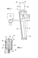
- Fig. 4 is an enlarged side view of a knob portion of the lever assembly of Fig. 1;
- FIG. 5 is a perspective view of a portion of a vehicle armrest control panel with a second embodiment of a lever knob assembly according to the present invention
- FIG. 6 is a perspective exploded view of the knob assembly of Fig. 5;
- Fig. 7 is a perspective exploded view of the outer housing of Figs. 5 and 6;
- Fig. 8 is another perspective view of the lever knob assembly of Fig. 5.
- a speed lever assembly 10 includes a housing 12, such as forms part of an armrest (not shown) in a vehicle.
- the housing 12 includes a guide plate 13 with an upper surface 14 and in which is formed a conventional shift lever gate or slot 16.
- the housing includes front wall 18, side wall 20, rear wall 22 and base 24.
- a lever 30 has an inner end 27 pivotally coupled to the base 24 at pivot 25, and an outer end 29 which projects substantially radially away from pivot 25 and is slidably received in the slot 16.
- the ends 27 and 29 define a main axis of the lever 30 which extends radially away from pivot 25.
- a knob assembly 32 is mounted on the outer end of lever 30.
- the assembly 10 may be used as a control input for a transmission, such as an infinitely variable transmission.
- a support arm 44 projects from lever 30 substantially perpendicular to an axis of end 29.
- Arm 44 includes a bore 46 which receives a conventional rotary encoder 48, such as an optical encoder.
- knob assembly 32 includes a cylindrical base plate 50 which is fixed to an end of the lever 30.
- Assembly 32 also includes a generally cylindrical hollow outer housing 52 with a smoothly curved top surface 54 and cylindrical side wall 55.
- Housing 52 has an open end 56 which is removably attached to base 50, preferably in a snap fit manner.
- An opening 58 is formed in the housing 52 and extends less than 180 degrees in angular extent. As a result, more than half of the wheel 60 is enclosed by the housing 52.
- a cylindrical rotary wheel 60 is received in and partially enclosed within the housing 52.
- Wheel 60 preferably has a knurled outer surface, is mounted for rotation in the housing 52 and is retained therein by the base 50 and the side wall 55.
- the inside diameter of the side wall 55 is slightly larger than the outer diameter of the wheel 60.
- Housing 52 forms a lip 57 which defines an end of the opening 58 and which covers an end of the wheel 60, so that the housing or side wall completely surrounds an outer surface of one end of the wheel 60.
- Wheel 60 rotates about an axis which is substantially parallel to an axis of the upper end of the lever 30.
- the wheel 60 is preferably plastic and is molded onto a thin rigid wire or shaft or coupling member 62.
- the wire 62 extends though wheel 60 to a first end which is received by an alignment recess 64 formed in the center of an inner surface of the housing top 54.
- the wire 62 also extends through a central bore 66 in base 50 and through central bore 68 in lever 30 to a second end which is coupled to the rotary encoder 48.
- rotation of wheel 60 causes rotation of the sensing element (not shown) of encoder 48 so that encoder 48 will generate signals representing the position and rotation of wheel 60. These signals can be used as set speed signals in a transmission control system (not shown) in a known manner.
- an operator can rest his or her hand on the top of the knob 32 or can grasp knob 32 with the fingers and move lever 30 within the slot 16 without actuation of wheel 60. Or, while the hand is on the top of knob 32, the operator can also manipulate and rotate wheel 60 with the thumb or one or more fingers through the opening 58. The operator need not place his hand on or below the housing side wall 52, and, as a result, the knob 32 can be positioned close to the upper surface 14 of the guide plate 13.
- an armrest control panel housing 110 includes a conventional guide slot 112 which receives a control lever unit 114, such as a control lever for an infinitely variable transmission (IVT) (not shown).
- Lever unit 114 has a shaft 116 which has a lower end (not shown) which is pivotally supported in a known manner with respect to the housing 110.
- knob assembly 120 is mounted to the upper end of the shaft 116.
- knob assembly 120 includes an alignment member 122 which is received in a slot 124 which extends across the shaft 116 near the upper end thereof.
- Assembly 120 also includes inner housing pieces 126 and 128 which are attached to each other, to member 122 and thus to shaft 116 by a pair of screws 130.
- Inner housing pieces 126, 128 enclose a conventional commercially available optical rotary position encoder 132.
- Pieces 126, 128 form an annular projection or rib 123 and a shoulder 125.
- Encoder 132 has box-shaped case 134 and a cylindrical sleeve 136 from which extends a rotatable sensing shaft 138 with a flat surface 140.
- a key slot 142 is formed on one side of sleeve 136.
- the upper ends 144, 146 of the inner housing pieces 126, 128 form an opening 148 through which extends the shaft 138.
- a tab 150 projects from end 144 and is received by slot 142 to prevent the case 134 from rotating with respect to the housing pieces 126, 128.
- a wheel assembly 152 is coupled to shaft 138 of encoder 132.
- the wheel assembly 152 and the encoder 132 are the same as the wheel assembly and sensor/encoder of US 6,404,187, except that in the present invention the wheel 152 and encoder have their axes oriented parallel to a longitudinal axis of lever shaft 116.
- Wheel assembly 152 includes a generally cylindrical hollow wheel 170 with a knurled outer surface 172 and a slightly tapered outer profile.
- An end cap 180 is received in the upper end of wheel 170.
- the wheel 170 and end cap 180 form a top surface which faces away from the lever shaft 116.
- An outer housing 154 is mounted over the wheel assembly 152 and the inner housing pieces 126, 128.
- Housing 154 is hollow and is fully open at its lower end 155.
- An opening 156 is formed in the upper portion of housing 154, and extends into a sidewall 158 and a top wall of the outer housing 154.
- a slot 162 in the lower end 155 receives a tab 164 which projects from an outer portion of inner housing piece 128 to prevent relative rotation between outer housing 154 and inner housing pieces 126, 128.
- the housing 154 includes an upper portion 159 which contains the opening 156 and a lower portion 161 which extends from upper portion 159 to the lower end 155 of housing 154.
- the length of lower portion 161 is as least as long as or longer than upper portion 159. This provides ample space for an operator to grasp the lower portion 161 without inadvertently contacting the wheel 170. Yet, an operator can easily move a thumb or finger upwardly to manipulate wheel 170.
- a portion of the wheel assembly 152 when assembled in the housing 154, a portion of the wheel assembly 152 is exposed and accessible through the opening 156.
- a portion of the top edge of wheel 170 and a portion of end cap 180 is exposed, and slightly less than half (in angular extent) of the outer side surface of wheel 170 is exposed.
Landscapes
- Engineering & Computer Science (AREA)
- General Engineering & Computer Science (AREA)
- Physics & Mathematics (AREA)
- General Physics & Mathematics (AREA)
- Automation & Control Theory (AREA)
- Mechanical Engineering (AREA)
- Mechanical Control Devices (AREA)
Abstract
Description
Claims (17)
- Control lever assembly having a lever (30) with a first end (27) - preferably pivotally - mounted in a housing and a second end (29) projecting away from the first end (27), a knob (32) mounted on the second end (29) of the lever (30), a wheel (60) rotatably mounted on the knob (32), and a rotary encoder (48) coupled to the wheel (60), characterized in, that:the knob (32) includes a hollow knob housing (52) having a side wall (55), the knob housing (52) - especially the side wall (55) - forming an opening (58) therein; andthe wheel (60) is received in the knob housing (52) for rotation therein about a rotation axis which is preferably substantially parallel to an axis which extends between the ends (27, 29) of the lever (30), the wheel (60) being accessible to an operator through said opening (58).
- The control lever assembly of claim 1, wherein:the knob housing (52) comprises a cylindrical base (50) attached to an end (29) of the lever (30) and the knob housing (52) or the side wall (55) is removably attached to the base (50).
- The control lever assembly of claim 1 or 2, wherein:a coupling member (62) couples the wheel (60) with the encoder (48), the coupling member (62) preferably extending through a bore (66) in the base (50).
- The control lever assembly of claim 3, wherein:the coupling member (62) having an end which is received by an alignment recess (64) formed on an inner surface of the knob housing (52).
- The control lever assembly of claim 3, wherein:the coupling member (62) extending through the wheel (60) to a first end which is received by an alignment recess (64) formed on an inner surface of the knob housing (52) and to a second end which is coupled to the encoder (48).
- The control lever assembly of claim 3, wherein:the coupling member (62) extending through the wheel (60), through a bore (66) in the base (50) and through a bore (68) in a portion of the lever (30).
- The control lever assembly according to one of the claims1 to 6, wherein:a portion of the knob housing (52) completely surrounds an end of the wheel (60), preferably an outer surface of one end of the wheel (60).
- The control lever assembly according to one of the claims1 to 7, wherein:the knob housing (52) includes a lip portion (57) which defines one end of the opening (58) and which partially covers an end of the wheel (60).
- The control lever assembly according to one of the claims1 to 8, wherein:the rotary encoder (48) is mounted on the lever (30, 44) and spaced apart from the knob (32).
- The control lever assembly according to one of the claims1 to 9, wherein:a bracket (44) projects from the lever (30) and the rotary encoder (48) is mounted in a bore (46) in the bracket (44).
- The control lever assembly according to one of the claims1 to 10, wherein:the side wall (55) of the knob housing (52) is generally cylindrical.
- The control lever assembly according to one of the claims1 to 11, wherein:the knob housing (52, 154) comprises a top wall (159) joined to and enclosing one end of the side wall (55, 161), the opening (58, 156) extends part way into the side wall (55, 161) and the top wall (159); and
- The control lever assembly according to one of the claims1 to 12, wherein:the wheel (170) comprises a top surface (180) facing away from the end of the lever (114) and a generally cylindrical side surface (172), a portion of the wheel topsurface (180) and side surface (172) being exposed through the opening (156).
- The control lever assembly of claim 13, wherein:the knob housing (154) includes an upper portion (159) which contains the opening (156) and a lower portion (161) which extends from the upper portion (159) to a lower end (155) of the knob housing (154), and in an axial direction, the lower portion (161) is longer than the upper portion (159).
- The control lever assembly of claim 13 or 14, further comprising:an inner housing (126, 128) attached to an end of the lever (114) and enclosing a portion of the encoder (132), the inner housing (126, 128) being enclosed by the knob housing (154).
- The control lever assembly according to one of the claims13 to 15, wherein:the knob housing (154) is releasably attached to the inner housing (126, 128), preferably in a snap-fit manner.
- The control lever assembly according to one of the claims13 to 16, wherein:the inner housing (126, 128) comprises a first housing part (126) and a second housing part (128) clamped together and to the end of the lever (114).
Applications Claiming Priority (4)
| Application Number | Priority Date | Filing Date | Title |
|---|---|---|---|
| US10/870,246 US20060000304A1 (en) | 2004-06-17 | 2004-06-17 | Control lever with partially enclosed rotary wheel |
| US870246 | 2004-06-17 | ||
| US951159 | 2004-09-27 | ||
| US10/951,159 US20060070482A1 (en) | 2004-06-17 | 2004-09-27 | Control lever with rotary wheel |
Publications (3)
| Publication Number | Publication Date |
|---|---|
| EP1607659A2 true EP1607659A2 (en) | 2005-12-21 |
| EP1607659A3 EP1607659A3 (en) | 2009-09-16 |
| EP1607659B1 EP1607659B1 (en) | 2014-06-18 |
Family
ID=34940189
Family Applications (1)
| Application Number | Title | Priority Date | Filing Date |
|---|---|---|---|
| EP05105318.9A Expired - Lifetime EP1607659B1 (en) | 2004-06-17 | 2005-06-16 | Control lever with partially enclosed rotary wheel |
Country Status (4)
| Country | Link |
|---|---|
| US (1) | US20060070482A1 (en) |
| EP (1) | EP1607659B1 (en) |
| BR (1) | BRPI0503879A (en) |
| ES (1) | ES2502792T3 (en) |
Cited By (1)
| Publication number | Priority date | Publication date | Assignee | Title |
|---|---|---|---|---|
| DE102007005253A1 (en) * | 2007-02-02 | 2008-08-07 | Deere & Company, Moline | Operating device for a vehicle |
Families Citing this family (12)
| Publication number | Priority date | Publication date | Assignee | Title |
|---|---|---|---|---|
| US20090139360A1 (en) * | 2007-11-30 | 2009-06-04 | Caterpillar Inc | Joystick attachment |
| US7913798B2 (en) * | 2008-03-07 | 2011-03-29 | Deere & Company | Armrest mounted grader control |
| JP6096480B2 (en) * | 2012-11-16 | 2017-03-15 | デルタ工業株式会社 | Shift lever knob assembly structure |
| JP5973887B2 (en) * | 2012-11-16 | 2016-08-23 | デルタ工業株式会社 | Button structure of knob for shift lever |
| US20140191558A1 (en) * | 2013-01-08 | 2014-07-10 | Caterpillar Inc. | Operator panel for a machine |
| US9817430B2 (en) * | 2013-02-22 | 2017-11-14 | Karim Messadek | Protective apparatuses for rotary control knobs |
| US20140237790A1 (en) * | 2013-02-22 | 2014-08-28 | Karim Messadek | Protective apparatuses for rotary control knobs |
| JP5861669B2 (en) * | 2013-06-03 | 2016-02-16 | コベルコ建機株式会社 | Construction machinery |
| US9541943B2 (en) * | 2013-07-22 | 2017-01-10 | Kubota Corporation | Operation lever and grip |
| USD779400S1 (en) * | 2016-01-21 | 2017-02-21 | Pilot, Inc. | Shift knob cover |
| USD816622S1 (en) * | 2016-10-28 | 2018-05-01 | Hon Hai Precision Industry Co., Ltd. | Knob |
| USD848239S1 (en) * | 2017-10-06 | 2019-05-14 | Harman International Industries, Incorporated | Control knob |
Citations (1)
| Publication number | Priority date | Publication date | Assignee | Title |
|---|---|---|---|---|
| US6404187B1 (en) | 1999-07-31 | 2002-06-11 | Deere & Company | Actuator/sensor assembly |
Family Cites Families (22)
| Publication number | Priority date | Publication date | Assignee | Title |
|---|---|---|---|---|
| US2543450A (en) * | 1947-05-13 | 1951-02-27 | Luther W Feagin | Control stick |
| US2611042A (en) * | 1949-04-28 | 1952-09-16 | Soundscriber Corp | Combined hand microphone and control means |
| US2787746A (en) * | 1954-07-23 | 1957-04-02 | Chance Vought Aircraft Inc | Auxiliary servo control hand grip for a manually operable control lever |
| US3814871A (en) * | 1973-03-21 | 1974-06-04 | Mc Gill Mfg Co | Joystick controller for multiple switch assembly |
| US3867600A (en) * | 1973-05-17 | 1975-02-18 | Us Navy | Hand-held control means |
| US4105882A (en) * | 1977-03-03 | 1978-08-08 | Columbus Mckinnon Corporation | Control station switch |
| US4131771A (en) * | 1977-04-06 | 1978-12-26 | Becton, Dickinson Electronics Company | Rotary switch with spaced circuit boards and discrete contacts on rotor opposite faces electrically insulated from furthermost board |
| US4406931A (en) * | 1982-06-23 | 1983-09-27 | Amp Incorporated | Joystick switch |
| US4590339A (en) * | 1985-02-19 | 1986-05-20 | Gravis Computer Peripherals Inc. | Joystick |
| JPS61249881A (en) * | 1985-04-30 | 1986-11-07 | 本田技研工業株式会社 | Mounting structure of switches for vehicles such as motorcycles |
| US4896558A (en) * | 1988-06-01 | 1990-01-30 | Deere & Company | Control handle for a work vehicle |
| US4857881A (en) * | 1988-07-08 | 1989-08-15 | Hayes Technology | Joystick with spring disconnect |
| US5614701A (en) * | 1995-06-27 | 1997-03-25 | Hung; Michael | Control switch for electric winch |
| DE29607920U1 (en) * | 1996-05-02 | 1996-06-20 | Zabel GmbH, 47800 Krefeld | Control device, in particular for the control of machines |
| US6145401A (en) * | 1997-11-21 | 2000-11-14 | Caterpillar Inc. | Modular control handle |
| DE19837163C1 (en) * | 1998-08-17 | 2000-03-16 | Deere & Co | Hand control lever |
| DE19924791C1 (en) * | 1999-05-29 | 2001-02-08 | Deere & Co | Switching device for motor vehicle transmissions |
| JP2002108472A (en) * | 2000-09-29 | 2002-04-10 | Japan Aviation Electronics Industry Ltd | Joystick device |
| JP2003099139A (en) * | 2001-07-03 | 2003-04-04 | Matsushita Electric Ind Co Ltd | Operation lever device |
| US6892597B2 (en) * | 2001-07-27 | 2005-05-17 | Pelco | Joystick |
| US7293625B2 (en) * | 2001-11-05 | 2007-11-13 | Hitachi Construction Machinery Co., Ltd. | Operating lever device for construction machine and construction machine |
| US20060000304A1 (en) * | 2004-06-17 | 2006-01-05 | Deere & Company, A Delaware Corporation | Control lever with partially enclosed rotary wheel |
-
2004
- 2004-09-27 US US10/951,159 patent/US20060070482A1/en not_active Abandoned
-
2005
- 2005-06-16 ES ES05105318.9T patent/ES2502792T3/en not_active Expired - Lifetime
- 2005-06-16 EP EP05105318.9A patent/EP1607659B1/en not_active Expired - Lifetime
- 2005-09-26 BR BRPI0503879-0A patent/BRPI0503879A/en not_active IP Right Cessation
Patent Citations (1)
| Publication number | Priority date | Publication date | Assignee | Title |
|---|---|---|---|---|
| US6404187B1 (en) | 1999-07-31 | 2002-06-11 | Deere & Company | Actuator/sensor assembly |
Cited By (2)
| Publication number | Priority date | Publication date | Assignee | Title |
|---|---|---|---|---|
| DE102007005253A1 (en) * | 2007-02-02 | 2008-08-07 | Deere & Company, Moline | Operating device for a vehicle |
| US7823685B2 (en) | 2007-02-02 | 2010-11-02 | Deere & Company | Operating device for a vehicle |
Also Published As
| Publication number | Publication date |
|---|---|
| BRPI0503879A (en) | 2006-05-09 |
| ES2502792T3 (en) | 2014-10-06 |
| EP1607659A3 (en) | 2009-09-16 |
| US20060070482A1 (en) | 2006-04-06 |
| EP1607659B1 (en) | 2014-06-18 |
Similar Documents
| Publication | Publication Date | Title |
|---|---|---|
| EP1607659B1 (en) | Control lever with partially enclosed rotary wheel | |
| EP1585015B1 (en) | User interface device | |
| US5912661A (en) | Z-encoder mechanism | |
| JP5037480B2 (en) | Operating wheel and handle system with tactile feedback | |
| US9517408B2 (en) | Multimode controller for video games | |
| US4721274A (en) | Gimbal assembly | |
| US20050044718A1 (en) | Hair trimmer with trim length adjustment mechanism | |
| US6091035A (en) | Lockout mechanism for power tool | |
| JP4046052B2 (en) | Comb vibration prevention structure of hair cutter | |
| CN112335408B (en) | Adjustable electrical control handle for a lawn mower | |
| WO2011033193A1 (en) | Rotary control device with haptic feedback | |
| US10299973B2 (en) | Motorized wheelchair for disabled or elderly users | |
| JP3335146B2 (en) | Steering wheel | |
| US20230097043A1 (en) | Computer input device | |
| JPH0839990A (en) | Device for drawing circular arc | |
| EP2067659B1 (en) | Lever switch device | |
| US7275457B2 (en) | Control lever with partially enclosed rotary wheel | |
| US8610010B2 (en) | Control element for a motor vehicle | |
| FR2879018A1 (en) | MULTIDIRECTIONAL ACTUATOR WITH VARIABLE RECALL EFFORT | |
| KR102557502B1 (en) | Knob device | |
| US6119352A (en) | Manual left or right hand can opener | |
| KR20160111651A (en) | Control apparatus using dial and vehicle comprising the same | |
| JP3665531B2 (en) | Endoscope operation device | |
| US20070057974A1 (en) | Scroll button assembly for video game controller | |
| JP3504760B2 (en) | Speed change device for bicycle |
Legal Events
| Date | Code | Title | Description |
|---|---|---|---|
| PUAI | Public reference made under article 153(3) epc to a published international application that has entered the european phase |
Free format text: ORIGINAL CODE: 0009012 |
|
| AK | Designated contracting states |
Kind code of ref document: A2 Designated state(s): AT BE BG CH CY CZ DE DK EE ES FI FR GB GR HU IE IS IT LI LT LU MC NL PL PT RO SE SI SK TR |
|
| AX | Request for extension of the european patent |
Extension state: AL BA HR LV MK YU |
|
| PUAL | Search report despatched |
Free format text: ORIGINAL CODE: 0009013 |
|
| AK | Designated contracting states |
Kind code of ref document: A3 Designated state(s): AT BE BG CH CY CZ DE DK EE ES FI FR GB GR HU IE IS IT LI LT LU MC NL PL PT RO SE SI SK TR |
|
| AX | Request for extension of the european patent |
Extension state: AL BA HR LV MK YU |
|
| 17P | Request for examination filed |
Effective date: 20100316 |
|
| AKX | Designation fees paid |
Designated state(s): AT BE BG CH CY CZ DE DK EE ES FI FR GB GR HU IE IS IT LI LT LU MC NL PL PT RO SE SI SK TR |
|
| 17Q | First examination report despatched |
Effective date: 20100531 |
|
| 17Q | First examination report despatched |
Effective date: 20110412 |
|
| GRAP | Despatch of communication of intention to grant a patent |
Free format text: ORIGINAL CODE: EPIDOSNIGR1 |
|
| INTG | Intention to grant announced |
Effective date: 20140108 |
|
| GRAS | Grant fee paid |
Free format text: ORIGINAL CODE: EPIDOSNIGR3 |
|
| GRAA | (expected) grant |
Free format text: ORIGINAL CODE: 0009210 |
|
| AK | Designated contracting states |
Kind code of ref document: B1 Designated state(s): AT BE BG CH CY CZ DE DK EE ES FI FR GB GR HU IE IS IT LI LT LU MC NL PL PT RO SE SI SK TR |
|
| REG | Reference to a national code |
Ref country code: GB Ref legal event code: FG4D |
|
| REG | Reference to a national code |
Ref country code: CH Ref legal event code: EP |
|
| REG | Reference to a national code |
Ref country code: AT Ref legal event code: REF Ref document number: 673540 Country of ref document: AT Kind code of ref document: T Effective date: 20140715 |
|
| REG | Reference to a national code |
Ref country code: IE Ref legal event code: FG4D |
|
| REG | Reference to a national code |
Ref country code: DE Ref legal event code: R096 Ref document number: 602005043924 Country of ref document: DE Effective date: 20140731 |
|
| REG | Reference to a national code |
Ref country code: ES Ref legal event code: FG2A Ref document number: 2502792 Country of ref document: ES Kind code of ref document: T3 Effective date: 20141006 |
|
| PG25 | Lapsed in a contracting state [announced via postgrant information from national office to epo] |
Ref country code: GR Free format text: LAPSE BECAUSE OF FAILURE TO SUBMIT A TRANSLATION OF THE DESCRIPTION OR TO PAY THE FEE WITHIN THE PRESCRIBED TIME-LIMIT Effective date: 20140919 Ref country code: FI Free format text: LAPSE BECAUSE OF FAILURE TO SUBMIT A TRANSLATION OF THE DESCRIPTION OR TO PAY THE FEE WITHIN THE PRESCRIBED TIME-LIMIT Effective date: 20140618 Ref country code: CY Free format text: LAPSE BECAUSE OF FAILURE TO SUBMIT A TRANSLATION OF THE DESCRIPTION OR TO PAY THE FEE WITHIN THE PRESCRIBED TIME-LIMIT Effective date: 20140618 Ref country code: LT Free format text: LAPSE BECAUSE OF FAILURE TO SUBMIT A TRANSLATION OF THE DESCRIPTION OR TO PAY THE FEE WITHIN THE PRESCRIBED TIME-LIMIT Effective date: 20140618 |
|
| REG | Reference to a national code |
Ref country code: NL Ref legal event code: VDEP Effective date: 20140618 |
|
| REG | Reference to a national code |
Ref country code: AT Ref legal event code: MK05 Ref document number: 673540 Country of ref document: AT Kind code of ref document: T Effective date: 20140618 |
|
| REG | Reference to a national code |
Ref country code: LT Ref legal event code: MG4D |
|
| PG25 | Lapsed in a contracting state [announced via postgrant information from national office to epo] |
Ref country code: SE Free format text: LAPSE BECAUSE OF FAILURE TO SUBMIT A TRANSLATION OF THE DESCRIPTION OR TO PAY THE FEE WITHIN THE PRESCRIBED TIME-LIMIT Effective date: 20140618 |
|
| PG25 | Lapsed in a contracting state [announced via postgrant information from national office to epo] |
Ref country code: RO Free format text: LAPSE BECAUSE OF FAILURE TO SUBMIT A TRANSLATION OF THE DESCRIPTION OR TO PAY THE FEE WITHIN THE PRESCRIBED TIME-LIMIT Effective date: 20140618 Ref country code: PT Free format text: LAPSE BECAUSE OF FAILURE TO SUBMIT A TRANSLATION OF THE DESCRIPTION OR TO PAY THE FEE WITHIN THE PRESCRIBED TIME-LIMIT Effective date: 20141020 Ref country code: SK Free format text: LAPSE BECAUSE OF FAILURE TO SUBMIT A TRANSLATION OF THE DESCRIPTION OR TO PAY THE FEE WITHIN THE PRESCRIBED TIME-LIMIT Effective date: 20140618 Ref country code: EE Free format text: LAPSE BECAUSE OF FAILURE TO SUBMIT A TRANSLATION OF THE DESCRIPTION OR TO PAY THE FEE WITHIN THE PRESCRIBED TIME-LIMIT Effective date: 20140618 Ref country code: CZ Free format text: LAPSE BECAUSE OF FAILURE TO SUBMIT A TRANSLATION OF THE DESCRIPTION OR TO PAY THE FEE WITHIN THE PRESCRIBED TIME-LIMIT Effective date: 20140618 |
|
| PG25 | Lapsed in a contracting state [announced via postgrant information from national office to epo] |
Ref country code: PL Free format text: LAPSE BECAUSE OF FAILURE TO SUBMIT A TRANSLATION OF THE DESCRIPTION OR TO PAY THE FEE WITHIN THE PRESCRIBED TIME-LIMIT Effective date: 20140618 Ref country code: IS Free format text: LAPSE BECAUSE OF FAILURE TO SUBMIT A TRANSLATION OF THE DESCRIPTION OR TO PAY THE FEE WITHIN THE PRESCRIBED TIME-LIMIT Effective date: 20141018 Ref country code: AT Free format text: LAPSE BECAUSE OF FAILURE TO SUBMIT A TRANSLATION OF THE DESCRIPTION OR TO PAY THE FEE WITHIN THE PRESCRIBED TIME-LIMIT Effective date: 20140618 Ref country code: NL Free format text: LAPSE BECAUSE OF FAILURE TO SUBMIT A TRANSLATION OF THE DESCRIPTION OR TO PAY THE FEE WITHIN THE PRESCRIBED TIME-LIMIT Effective date: 20140618 |
|
| REG | Reference to a national code |
Ref country code: DE Ref legal event code: R097 Ref document number: 602005043924 Country of ref document: DE |
|
| PLBE | No opposition filed within time limit |
Free format text: ORIGINAL CODE: 0009261 |
|
| STAA | Information on the status of an ep patent application or granted ep patent |
Free format text: STATUS: NO OPPOSITION FILED WITHIN TIME LIMIT |
|
| PG25 | Lapsed in a contracting state [announced via postgrant information from national office to epo] |
Ref country code: DK Free format text: LAPSE BECAUSE OF FAILURE TO SUBMIT A TRANSLATION OF THE DESCRIPTION OR TO PAY THE FEE WITHIN THE PRESCRIBED TIME-LIMIT Effective date: 20140618 |
|
| 26N | No opposition filed |
Effective date: 20150319 |
|
| PG25 | Lapsed in a contracting state [announced via postgrant information from national office to epo] |
Ref country code: BE Free format text: LAPSE BECAUSE OF FAILURE TO SUBMIT A TRANSLATION OF THE DESCRIPTION OR TO PAY THE FEE WITHIN THE PRESCRIBED TIME-LIMIT Effective date: 20140618 |
|
| PG25 | Lapsed in a contracting state [announced via postgrant information from national office to epo] |
Ref country code: SI Free format text: LAPSE BECAUSE OF FAILURE TO SUBMIT A TRANSLATION OF THE DESCRIPTION OR TO PAY THE FEE WITHIN THE PRESCRIBED TIME-LIMIT Effective date: 20140618 |
|
| PG25 | Lapsed in a contracting state [announced via postgrant information from national office to epo] |
Ref country code: MC Free format text: LAPSE BECAUSE OF FAILURE TO SUBMIT A TRANSLATION OF THE DESCRIPTION OR TO PAY THE FEE WITHIN THE PRESCRIBED TIME-LIMIT Effective date: 20140618 Ref country code: IT Free format text: LAPSE BECAUSE OF NON-PAYMENT OF DUE FEES Effective date: 20150616 |
|
| REG | Reference to a national code |
Ref country code: CH Ref legal event code: PL |
|
| GBPC | Gb: european patent ceased through non-payment of renewal fee |
Effective date: 20150616 |
|
| PG25 | Lapsed in a contracting state [announced via postgrant information from national office to epo] |
Ref country code: LU Free format text: LAPSE BECAUSE OF FAILURE TO SUBMIT A TRANSLATION OF THE DESCRIPTION OR TO PAY THE FEE WITHIN THE PRESCRIBED TIME-LIMIT Effective date: 20150616 |
|
| REG | Reference to a national code |
Ref country code: IE Ref legal event code: MM4A |
|
| PG25 | Lapsed in a contracting state [announced via postgrant information from national office to epo] |
Ref country code: CH Free format text: LAPSE BECAUSE OF NON-PAYMENT OF DUE FEES Effective date: 20150630 Ref country code: LI Free format text: LAPSE BECAUSE OF NON-PAYMENT OF DUE FEES Effective date: 20150630 Ref country code: GB Free format text: LAPSE BECAUSE OF NON-PAYMENT OF DUE FEES Effective date: 20150616 Ref country code: IE Free format text: LAPSE BECAUSE OF NON-PAYMENT OF DUE FEES Effective date: 20150616 |
|
| REG | Reference to a national code |
Ref country code: FR Ref legal event code: PLFP Year of fee payment: 12 |
|
| PGFP | Annual fee paid to national office [announced via postgrant information from national office to epo] |
Ref country code: FR Payment date: 20160628 Year of fee payment: 12 |
|
| REG | Reference to a national code |
Ref country code: ES Ref legal event code: FD2A Effective date: 20161129 |
|
| PG25 | Lapsed in a contracting state [announced via postgrant information from national office to epo] |
Ref country code: ES Free format text: LAPSE BECAUSE OF NON-PAYMENT OF DUE FEES Effective date: 20150617 |
|
| PG25 | Lapsed in a contracting state [announced via postgrant information from national office to epo] |
Ref country code: HU Free format text: LAPSE BECAUSE OF FAILURE TO SUBMIT A TRANSLATION OF THE DESCRIPTION OR TO PAY THE FEE WITHIN THE PRESCRIBED TIME-LIMIT; INVALID AB INITIO Effective date: 20050616 |
|
| PG25 | Lapsed in a contracting state [announced via postgrant information from national office to epo] |
Ref country code: BG Free format text: LAPSE BECAUSE OF FAILURE TO SUBMIT A TRANSLATION OF THE DESCRIPTION OR TO PAY THE FEE WITHIN THE PRESCRIBED TIME-LIMIT Effective date: 20150630 |
|
| PG25 | Lapsed in a contracting state [announced via postgrant information from national office to epo] |
Ref country code: TR Free format text: LAPSE BECAUSE OF FAILURE TO SUBMIT A TRANSLATION OF THE DESCRIPTION OR TO PAY THE FEE WITHIN THE PRESCRIBED TIME-LIMIT Effective date: 20140618 |
|
| REG | Reference to a national code |
Ref country code: FR Ref legal event code: ST Effective date: 20180228 |
|
| PG25 | Lapsed in a contracting state [announced via postgrant information from national office to epo] |
Ref country code: FR Free format text: LAPSE BECAUSE OF NON-PAYMENT OF DUE FEES Effective date: 20170630 |
|
| PGFP | Annual fee paid to national office [announced via postgrant information from national office to epo] |
Ref country code: DE Payment date: 20190521 Year of fee payment: 15 |
|
| REG | Reference to a national code |
Ref country code: DE Ref legal event code: R119 Ref document number: 602005043924 Country of ref document: DE |
|
| PG25 | Lapsed in a contracting state [announced via postgrant information from national office to epo] |
Ref country code: DE Free format text: LAPSE BECAUSE OF NON-PAYMENT OF DUE FEES Effective date: 20210101 |