EP1607352A2 - A system for conveying ceramic shaped bodies - Google Patents
A system for conveying ceramic shaped bodies Download PDFInfo
- Publication number
- EP1607352A2 EP1607352A2 EP05017758A EP05017758A EP1607352A2 EP 1607352 A2 EP1607352 A2 EP 1607352A2 EP 05017758 A EP05017758 A EP 05017758A EP 05017758 A EP05017758 A EP 05017758A EP 1607352 A2 EP1607352 A2 EP 1607352A2
- Authority
- EP
- European Patent Office
- Prior art keywords
- ceramic shaped
- conveying
- shaped bodies
- cradle
- conveyor
- Prior art date
- Legal status (The legal status is an assumption and is not a legal conclusion. Google has not performed a legal analysis and makes no representation as to the accuracy of the status listed.)
- Withdrawn
Links
Images



Classifications
-
- B—PERFORMING OPERATIONS; TRANSPORTING
- B65—CONVEYING; PACKING; STORING; HANDLING THIN OR FILAMENTARY MATERIAL
- B65G—TRANSPORT OR STORAGE DEVICES, e.g. CONVEYORS FOR LOADING OR TIPPING, SHOP CONVEYOR SYSTEMS OR PNEUMATIC TUBE CONVEYORS
- B65G49/00—Conveying systems characterised by their application for specified purposes not otherwise provided for
- B65G49/05—Conveying systems characterised by their application for specified purposes not otherwise provided for for fragile or damageable materials or articles
- B65G49/08—Conveying systems characterised by their application for specified purposes not otherwise provided for for fragile or damageable materials or articles for ceramic mouldings
-
- B—PERFORMING OPERATIONS; TRANSPORTING
- B28—WORKING CEMENT, CLAY, OR STONE
- B28B—SHAPING CLAY OR OTHER CERAMIC COMPOSITIONS; SHAPING SLAG; SHAPING MIXTURES CONTAINING CEMENTITIOUS MATERIAL, e.g. PLASTER
- B28B13/00—Feeding the unshaped material to moulds or apparatus for producing shaped articles; Discharging shaped articles from such moulds or apparatus
- B28B13/04—Discharging the shaped articles
-
- B—PERFORMING OPERATIONS; TRANSPORTING
- B65—CONVEYING; PACKING; STORING; HANDLING THIN OR FILAMENTARY MATERIAL
- B65G—TRANSPORT OR STORAGE DEVICES, e.g. CONVEYORS FOR LOADING OR TIPPING, SHOP CONVEYOR SYSTEMS OR PNEUMATIC TUBE CONVEYORS
- B65G47/00—Article or material-handling devices associated with conveyors; Methods employing such devices
- B65G47/52—Devices for transferring articles or materials between conveyors i.e. discharging or feeding devices
- B65G47/53—Devices for transferring articles or materials between conveyors i.e. discharging or feeding devices between conveyors which cross one another
-
- B—PERFORMING OPERATIONS; TRANSPORTING
- B65—CONVEYING; PACKING; STORING; HANDLING THIN OR FILAMENTARY MATERIAL
- B65G—TRANSPORT OR STORAGE DEVICES, e.g. CONVEYORS FOR LOADING OR TIPPING, SHOP CONVEYOR SYSTEMS OR PNEUMATIC TUBE CONVEYORS
- B65G47/00—Article or material-handling devices associated with conveyors; Methods employing such devices
- B65G47/74—Feeding, transfer, or discharging devices of particular kinds or types
- B65G47/90—Devices for picking-up and depositing articles or materials
-
- B—PERFORMING OPERATIONS; TRANSPORTING
- B65—CONVEYING; PACKING; STORING; HANDLING THIN OR FILAMENTARY MATERIAL
- B65G—TRANSPORT OR STORAGE DEVICES, e.g. CONVEYORS FOR LOADING OR TIPPING, SHOP CONVEYOR SYSTEMS OR PNEUMATIC TUBE CONVEYORS
- B65G2201/00—Indexing codes relating to handling devices, e.g. conveyors, characterised by the type of product or load being conveyed or handled
- B65G2201/02—Articles
- B65G2201/0235—Containers
- B65G2201/0261—Puck as article support
-
- B—PERFORMING OPERATIONS; TRANSPORTING
- B65—CONVEYING; PACKING; STORING; HANDLING THIN OR FILAMENTARY MATERIAL
- B65G—TRANSPORT OR STORAGE DEVICES, e.g. CONVEYORS FOR LOADING OR TIPPING, SHOP CONVEYOR SYSTEMS OR PNEUMATIC TUBE CONVEYORS
- B65G2207/00—Indexing codes relating to constructional details, configuration and additional features of a handling device, e.g. Conveyors
- B65G2207/28—Impact protection
Definitions
- the present invention relates to a system for conveying ceramic shaped bodies on and along a conveying path in the state that the ceramic shaped bodies are placed on cradles.
- the present invention also relates to such cradles used for the conveying system.
- ceramic shaped bodies are obtained by molding a ceramic material and cut in a given length. Then, the cut ceramic shaped bodies are individually placed on cradles, and the cradles on which the ceramic shaped bodies are placed are moved along a conveyor path. After that, a given number (for example, five) of the ceramic shaped bodies are aligned and dried, and both end faces of the dried ceramic shaped bodies are cut and finish worked. Finally, the thus finish worked ceramic shaped bodies are fired to obtain ceramic products.
- a given number for example, five
- the conveyor path needs, in some cases, to change its conveying direction on the way due to a downstream process layout such as a factory layout or a dryer layout.
- a downstream process layout such as a factory layout or a dryer layout.
- the cradles are stopped at a terminal end of a first conveyor path by bumping them against a stopper, and the cradles are pushed to another conveying direction by a plunger or the like to transfer to the next conveyor path.
- the cradle is conventionally stopped at the terminal end of the conveyor path by bumping it against a stopper, then the next cradle bumps against the stopped cradle, and this operation continues until the cradles at least required for aligning are acquired.
- thin-walled ceramic honeycomb shaped bodies having a cell-wall thickness of 120 ⁇ m or less and a cell density of about 400- 1600 cell/sq. in. which have been highly demanded these days, are much weaker than the conventional shaped bodies especially in the green state.
- the ceramic shaped body are deformed, cracked or, in an extreme case, even broken with a shock of bumping upon stopping or changing the conveying direction of the ceramic shaped bodies, or a shock caused by the plunger upon pushing.
- the strengths of the thin-walled ceramic honeycomb shaped bodies have directionality. It is strong against an impact in the axis direction, relatively strong against an impact in the vertical direction to the cradle as it is supported by the cradle, and extremely weak against an impact in the horizontal direction.
- a first aspect of the system for conveying ceramic shaped bodies according to the present invention is the system for conveying ceramic shaped bodies on and along a conveyor, said system comprising cradles, a conveyor comprising first and second conveyor paths and a conveying direction-changing station, the ceramic shaped bodies being placed on the cradles and the cradles being conveyed on and along the conveyor, wherein a conveying direction of the ceramic shaped body is changed at the conveying direction-changing station while an impact on the ceramic shaped body is absorbed by lifting up the cradle from the first conveyor path, transferring the cradle to the second conveyor path having a different conveying direction from that of the first one while keeping the cradle lifted, and then putting down the cradle on the second conveyor path.
- a second aspect of the system for conveying ceramic shaped bodies according to the present invention is the system for conveying ceramic shaped bodies on and along a conveyor, said system comprising cradles and a conveyor, said ceramic shaped bodies being placed on said cradles and said cradles being conveyed on and along said conveyor, wherein the ceramic shaped bodies are stopped while impacts on the ceramic shaped bodies are absorbed by gradually reducing the conveying speed of the cradles on the conveyor to stop the cradle, when the cradles on which the ceramic shaped bodies are to be placed are stopped on the way of the conveyor.
- the impact on the ceramic shaped bodies can be absorbed by, according to the first aspect, lifting up the cradle from the first conveyor path, transferring the cradle to the second conveyor path having a different conveying direction from that of the first one while keeping the cradle lifted, and then putting down the cradle on the second conveyor when the conveying directions of the cradles on which the ceramic shaped bodies are placed are changed on the way of the conveyor, or by, according to the second aspect, gradually reducing the conveying speed of the cradles on the conveyor to stop the cradle on the way of the conveyor when the cradles on which the ceramic shaped body placed is stopped on the way of the conveyor. Accordingly, deformations, cracks and breakages of the ceramic shaped bodies during conveying can be prevented.
- the cradle used for the system for conveying the ceramic shaped bodies comprises a base preferably made of aluminum, a supporting member provided on the base, preferably made of foamed polystyrene, and having a receiving portion that is formed on a side opposed to the side contacting the base and is shaped corresponding to a shape of the ceramic shaped body, and a cushioning material provided to cover the receiving portion of the supporting member, whereby the cradle is to convey the ceramic shaped body while absorbing an impact on the ceramic shaped body.
- the ceramic shaped body can be received by the receiving portion of the foamed polystyrene supporting member of the cradle and the cushioning material covering the receiving portion. Therefore, even when a shock is applied on the ceramic shaped body, an impact can be effectively absorbed.
- the ceramic shaped body since the ceramic shaped body is held in a state that the cushioning material contacts the ceramic shaped body, the ceramic shaped body can be easily released from the cradle, the supporting member made of the easy-to-break, foamed polystyrene can be prevented from breaking, and thus the cradle can be reused.
- the entire cradle can be made light and less costly.
- the supporting member from foamed polystyrene, the entire cradle can be made light and less costly to make handling and attaching/detaching easy.
- the cradle can be easily worked, even if a diameter of the ceramic shaped body to be held is not the same as being expected due to a difference in shrinking factor, the supporting member can be worked afterward to hold such a ceramic shaped body if the diameter is larger than the expected one.
- the cushioning material is used for preventing the ceramic shaped body to be held from sliding too much and disturbing a slipping movement due to a large frictional resistance.
- the supporting member made of easy-to-break foamed polystyrene may be used in the cradle with the aforementioned configuration, since the cradle contacts the conveyor path via the aluminum base.
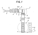
- FIG. 1 an apparatus including a system for conveying ceramic shaped bodies in accordance with one preferred embodiment of the present invention.
- a ceramic shaped body 2 formed into, for example, a cylindrical honeycomb shape by an extruder 1 is cut in a given length by a cutter 3.
- the ceramic shaped bodies 2 thus cut are individually placed on cradles 4.
- the cradles on which the ceramic shaped body 2 is places are conveyed over on and along conveyor 5.
- the conveyor 5 comprises a first conveyor path 5-1 having a given conveying direction and a second conveyor path 5-2 having a different conveying direction from that of the first one (in this figure, the direction is turned 90 degrees from the first conveying direction).
- Each of the first conveyor path 5-1 and the second conveyor path 5-2 comprises a plurality of self-running conveying rollers 6 of which rotational speed can be regulated by controlling a not-shown speed-control motor and a not-shown geared motor.
- a conveying direction-changing station 7 is provided between the first conveyor path 5-1 and the second conveyor path 5-2.
- a cradle-aligning station 8 is provided, which aligns and stops a given number (in this figure, five) of the cradles on which the ceramic shaped body 2 is placed at its terminal end.
- FIGS. 2(a), 2(b) and 2(c) are a top view, a front view and a side view, respectively, of a configuration of the conveying direction-changing station 7 in accordance with one embodiment of the first aspect of the present invention.
- FIGS. 2(a), 2(b) and 2(c) are a top view, a front view and a side view, respectively, of a configuration of the conveying direction-changing station 7 in accordance with one embodiment of the first aspect of the present invention.
- like elements as shown in FIG. 1 are given like reference numerals, and their description will be omitted.
- 2(a) - 2(c) is characterized in by being adapted to lift up the cradle 4 from the first conveyor path 5-1, transport it to the second conveyor path 5-2 while keeping the cradle lifted, and put it on the second conveyor path 5-2, when the conveying direction of the cradles on which the ceramic shaped body 2 is placed are changed on the way of the conveyor 5, thereby changing the conveying direction of the ceramic shaped body 2 with absorbing an impact on the ceramic shaped body 2.
- a plurality (in this figure, three) of claw members 11 which are movable in the vertical direction between the conveying rollers 6 as well as in the horizontal direction to the conveying rollers 6 are provided between the conveying rollers 6 of the first conveyor 5-1.
- the horizontal movement of the claw members 11 to the conveying rollers 6 is achieved by a servo motor 12, and vertical movement between the conveying rollers 6 by an air cylinder 13.
- FIGS. 2(a) - 2(c) steps of changing the conveying direction by the claw member 11 as shown in FIGS. 3(a) - 3(e) will be described now.
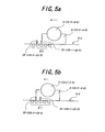
- the cradle 4 on which the ceramic shaped body 2 is placed is stopped upon contacting a stopper 14 at the conveying direction-changing station 7 (FIG. 3(a)). Then, the cradle is lifted up from the first conveyor path 5-1 by moving a plurality of the claw members 11 upwardly (FIG. 3(b)). After that, the cradle 4 on which the ceramic shaped body 2 is placed is transported onto the second conveyor 5-2 by moving the plurality of the claw members 11 in parallel to the conveying rollers 6 (FIG. 3(c)).
- the conveying rollers 15 are a part of the conveying rollers 6 constituting the second conveyor path 5-2 existing in the conveying direction-changing station 7. Rollers having evacuation areas 16 in positions corresponding to the positions of the claw members 11 so that the claw members 11 can be evacuated from a conveying plane of the second conveyor path 5-2 are use as the conveying rollers 15.
- FIG. 4 illustrates a configuration of the cradle-aligning station 8 in accordance with one embodiment of the second aspect of the present invention.
- like elements as shown in FIG. 1 are given like reference numerals, and their description will be omitted.
- the cradle-aligning station 8 is configured so that the conveying speed of the cradles 4 on the second conveyor 5-2 is gradually reduced to stop, thereby stopping the ceramic shaped body 2 with absorbing an impact on the ceramic shaped body 2.
- the rotational speed of groups of conveying rollers 6-1 to 6-5 each consisting of seven rollers and existing at the places where the cradles 4-1 to 4-5 should be stopped can be regulated by servomotors 21-1 to 21-5 respectively provided therefor, thereby gradually reducing each conveying speed of the cradles 4-1 to 4-5 on which the ceramic shaped bodies 2-1 to 2-5 are respectively placed on the cradle-aligning station 8 to stop.
- Each of the aforementioned speed-reducing sensors 22-1 to 22-5 and the stopping sensors 23-1 to 23-5 may be configured in any form as far as the light-emitter and the light-collector are so provided on both sides of the second conveyor path 5-2 that the light-collector may always accept light emitted from the light-emitter when the cradle does not pass over the sensor, and the light-collector does not accept light emitted form the light-emitter when the cradle passes over the sensor, thereby detecting the cradle passing over the sensor.
- the light-emitter 22-1a (22-2a to 22-5a) constituting the speed-reducing sensor 22-1 (22-2 to 22-5) and the light-emitter 23-1a (23-2a to 23-5a) constituting the stopping sensor 23-1 (23-2 to 23-5), or light-collectors 22-1b (22-2b to 22-5b) and 23-1b (23-2b to 23-5b) thereof are not placed on the same side of the conveyor path, as the speed-reducing sensor 22-1 (22-2 to 22-5) and the adjacent stopping sensor 23-1 (23-2 to 23-5) may be prevented from malfunctions caused by incoming light from the adjacent light-emitters.
- the pairs of the speed-reducing sensors 22-1 to 22-5 and the stopping sensors 23-1 to 23-5 are provided to be adjacent to a tip of each of the conveying rollers 6-1 to 6-5 as viewed in the conveying direction. The reason of this is to prevent the conveying time from being long since it would take a longer time before the cradles 4 come to a stop at a given point if the cradles start reducing their speeds too early by signals from the speed-reducing sensors 22-1 to 22-5.
- the configuration is not limited to the above example as far as the pairs of the speed-reducing sensors 22-1 to 22-5 and the stopping sensors 23-1 to 23-5 are provided along the conveying direction in the order of the speed-reducing sensors 22-1 to 22-5 and the stopping sensors 23-1 to 23-5 in each of the conveying rollers 6-1 to 6-5.
- the aforementioned controlling method of the conveying speed of the cradles 4 at the cradle-aligning station 8 is also applied to the conveying direction-changing station 7 where the cradles 4 are stopped at its terminal end.
- the aforementioned controlling method of the conveying rollers 6-1 with the speed-reducing sensor 22-1 and the stopping sensor 23-1 may be used as well.
- each set of the speed-reducing sensors 22-1 to 22-5, the stopping sensors 23-1 to 23-5, the conveying rollers 6-1 to 6-5 and the servomotors 21-1 to 21-5 is provided for each of the cradles to constitute a speed reduction conveying device of the cradle.
- an impact resistance of the thin-walled ceramic shaped body is taken into consideration, an action for loading it to a subsequent drying step should not be too quick to prevent excess acceleration from applying to the ceramic shaped body. Therefore, when productivity is also taken into consideration, it is preferable to load some ceramic shaped bodies in one action. To this end, it is necessary to provide waiting cradles and to apply the speed reduction conveying devices to a waiting station as well. For this reason, though the number of the devices may be changed as needed, it is preferable to adopt the minimum number of the devices for ensuring productivity and the waiting station.
- FIG. 7 is a sectional view of the cradle in accordance with one preferred embodiment of the present invention, which is used for the system for conveying ceramic shaped bodies, and on which the ceramic shaped body is placed.
- the cradle 4 comprises an aluminum base 31, a foamed polystyrene supporting member 33 provided on the base 31 and a non-woven fabric 34 as a cushioning material.
- the supporting member 33 has a receiving portion 32 formed on a side opposed to the side contacting the base 31 in a shape corresponding to a shape of the ceramic shaped body 2, for example, in this embodiment, in cylindrical shape.
- the non-woven fabric 34 is provided to cover the receiving portion 32 of the supporting member 33.
- the ceramic shaped body 2 can be received by the receiving portion 32 of the foamed polystyrene supporting member 33 and the non-woven fabric 34 covering the receiving portion 32, and an impact can be effectively absorbed by them even if a shock is applied on the cradle 4. Further, since the ceramic shaped body 2 is held in such a state that the non-woven fabric 34 and the ceramic shaped body 2 contact each other, the ceramic shaped body 2 can be easily removed from the cradle 4, and the foamed polystyrene supporting member 33, which is readily damaged, can be prevented from breaking. Therefore, the cradle can be reused.
- the cradle is lifted up from the first conveyor path, transferred to the second conveyor path having a different direction while keeping the ceramic shaped bodies lifted, and then put down on the second conveyor path when the conveying directions of the cradles on which the ceramic shaped bodies are placed are changed on the way of the conveyor, and since, in the second aspect of the present invention, the conveying speed of the cradles over the conveyor is gradually reducing to stop the cradle on the way of the conveyor, when the cradles on which the ceramic shaped bodies are placed are stopped on the way of the conveyor, the impact on the ceramic shaped bodies can be absorbed to prevent deformations, cracks and breakages of the ceramic shaped bodies upon conveying in each cases.
- the ceramic shaped body can be held by the receiving portion of the foamed polystyrene supporting member and the non-woven fabric covering the receiving portion of the cradle, and the impact on the shaped body is effectively absorbed by them even when the shock is applied to the cradle. Furthermore, since the ceramic shaped body is held in such a state that the non-woven fabric and the ceramic shaped body contact each other, the ceramic shaped body can be easily removed from the cradle, and the foamed polystyrene receiving portion, which is readily damaged, can be prevented from breaking, and thus the cradle can be reused.
- the following numbered paragraphs (paras.) contain statements of broad combinations of the inventive technical features herein disclosed:-
Landscapes
- Engineering & Computer Science (AREA)
- Mechanical Engineering (AREA)
- Ceramic Engineering (AREA)
- Manufacturing & Machinery (AREA)
- Chemical & Material Sciences (AREA)
- Devices For Post-Treatments, Processing, Supply, Discharge, And Other Processes (AREA)
- Attitude Control For Articles On Conveyors (AREA)
- Specific Conveyance Elements (AREA)
- Relays Between Conveyors (AREA)
Abstract
Description
Claims (3)
- A system for conveying ceramic shaped bodies on and along a conveyor, said system comprising cradles and a conveyor, said ceramic shaped bodies being placed on said cradles and said cradles being conveyed on and along said conveyor, wherein the ceramic shaped bodies are stopped while impacts on the ceramic shaped bodies are absorbed by gradually reducing the conveying speed of the cradles on the conveyor to stop the cradle, when the cradles on which the ceramic shaped bodies are to be placed are stopped on the way of the conveyor.
- A system for conveying ceramic shaped bodies as claimed in claim 1, wherein the conveyor comprises self-running conveying rollers, and the rotational speed of the cradles on which the ceramic shaped bodies are placed over the conveyor are gradually slowed down to stop by controlling the rotational speed of the conveying rollers.
- A system for conveying ceramic shaped bodies as claimed in claim 2, which further comprises a speed-reducing sensor and a stopping sensor each of which consists of a pair of an light-emitter and a light-collector are provided on each side of the conveyor, and the rotational speed of the conveying rollers begin to slow down at a point of time the cradle passes over the speed-reducing sensor, and the rotation is stopped at a point of time the cradle passes over the stopping sensor.
Applications Claiming Priority (3)
| Application Number | Priority Date | Filing Date | Title |
|---|---|---|---|
| JP2000232777 | 2000-08-01 | ||
| JP2000232777A JP4017324B2 (en) | 2000-08-01 | 2000-08-01 | Ceramic compact transport system |
| EP01306502A EP1177994B1 (en) | 2000-08-01 | 2001-07-30 | A system for conveying ceramic shaped bodies |
Related Parent Applications (1)
| Application Number | Title | Priority Date | Filing Date |
|---|---|---|---|
| EP01306502A Division EP1177994B1 (en) | 2000-08-01 | 2001-07-30 | A system for conveying ceramic shaped bodies |
Publications (2)
| Publication Number | Publication Date |
|---|---|
| EP1607352A2 true EP1607352A2 (en) | 2005-12-21 |
| EP1607352A3 EP1607352A3 (en) | 2006-01-11 |
Family
ID=18725400
Family Applications (3)
| Application Number | Title | Priority Date | Filing Date |
|---|---|---|---|
| EP01306502A Expired - Lifetime EP1177994B1 (en) | 2000-08-01 | 2001-07-30 | A system for conveying ceramic shaped bodies |
| EP05017758A Withdrawn EP1607352A3 (en) | 2000-08-01 | 2001-07-30 | A system for conveying ceramic shaped bodies |
| EP05017757A Withdrawn EP1604922A3 (en) | 2000-08-01 | 2001-07-30 | Cradle for a system for conveying ceramic shaped bodies |
Family Applications Before (1)
| Application Number | Title | Priority Date | Filing Date |
|---|---|---|---|
| EP01306502A Expired - Lifetime EP1177994B1 (en) | 2000-08-01 | 2001-07-30 | A system for conveying ceramic shaped bodies |
Family Applications After (1)
| Application Number | Title | Priority Date | Filing Date |
|---|---|---|---|
| EP05017757A Withdrawn EP1604922A3 (en) | 2000-08-01 | 2001-07-30 | Cradle for a system for conveying ceramic shaped bodies |
Country Status (6)
| Country | Link |
|---|---|
| US (1) | US6588577B2 (en) |
| EP (3) | EP1177994B1 (en) |
| JP (1) | JP4017324B2 (en) |
| CN (1) | CN1211267C (en) |
| DE (1) | DE60119843T2 (en) |
| ZA (1) | ZA200106309B (en) |
Families Citing this family (23)
| Publication number | Priority date | Publication date | Assignee | Title |
|---|---|---|---|---|
| CN100554197C (en) * | 2005-07-20 | 2009-10-28 | 亚洲光学股份有限公司 | Carrying mechanism for glass molding group |
| DE102006010393B4 (en) * | 2006-03-03 | 2010-06-24 | Maschinen- Und Stahlbau Julius Lippert Gmbh & Co. Kg | Device for handling deformation-prone, freshly extruded drawing body |
| WO2007129399A1 (en) * | 2006-05-08 | 2007-11-15 | Ibiden Co., Ltd. | Process for producing honeycomb structure, honeycomb molding receiving machine and honeycomb molding demounting machine |
| WO2007138701A1 (en) * | 2006-05-31 | 2007-12-06 | Ibiden Co., Ltd. | Holding device and method of producing honeycomb structure |
| US8292063B2 (en) | 2007-02-25 | 2012-10-23 | Fori Automation, Inc. | Pallet conveyor with corner assembly |
| US7708134B2 (en) | 2007-02-25 | 2010-05-04 | Fori Automation, Inc. | Power conveyor with corner assembly and pallet therefor |
| US9085089B2 (en) * | 2009-02-27 | 2015-07-21 | Corning Incorporated | Support tray for extruded ceramic ware and method |
| JP5449969B2 (en) | 2009-10-08 | 2014-03-19 | 日本碍子株式会社 | Carrier for conveying honeycomb molded body, conveying apparatus and conveying method using the same |
| CN101798226B (en) * | 2010-03-19 | 2012-05-23 | 中国电子科技集团公司第二研究所 | High-precision transporting device for processing multi-layer green ceramic chip |
| CN102139809A (en) * | 2011-04-21 | 2011-08-03 | 苏州工业园区高登威科技有限公司 | Steering roll shaft transmission device |
| JP5629729B2 (en) | 2012-06-27 | 2014-11-26 | 日本碍子株式会社 | Method for manufacturing ceramic honeycomb structure |
| JP5964205B2 (en) * | 2012-07-27 | 2016-08-03 | 住友化学株式会社 | Green honeycomb molded body pedestal and diesel particulate filter manufacturing method |
| CN102837957B (en) * | 2012-09-14 | 2014-11-05 | 广东摩德娜科技股份有限公司 | Large ceramic plate arranger |
| JP6027435B2 (en) * | 2012-12-27 | 2016-11-16 | 住友化学株式会社 | Manufacturing method of diesel particulate filter and cradle for green honeycomb molded body |
| CN103496581A (en) * | 2013-10-18 | 2014-01-08 | 连云港千樱医疗设备有限公司 | Toppling prevention type plastic soft bottle reversing and pushing conveying device |
| JP6155212B2 (en) | 2014-03-11 | 2017-06-28 | 日本碍子株式会社 | Carrier for conveying honeycomb molded body |
| CN104261112B (en) * | 2014-09-18 | 2016-08-17 | 湖北长方缘涂装设备有限公司 | A kind of right angle commutation transport production line |
| US9796505B1 (en) * | 2016-04-01 | 2017-10-24 | United Technologies Corporation | Billet support fingers for palletization |
| CN107718897A (en) * | 2017-06-20 | 2018-02-23 | 东莞市创明电池技术有限公司 | Cylindrical battery spray code spraying apparatus |
| JP2019136939A (en) * | 2018-02-09 | 2019-08-22 | 日本碍子株式会社 | Method for producing honeycomb molded body or fired article, pedestal, and method for producing this pedestal |
| JP6970133B2 (en) * | 2019-03-11 | 2021-11-24 | 日本碍子株式会社 | Honeycomb molded body pedestal, honeycomb molded body manufacturing method and honeycomb fired body manufacturing method |
| CN111802331B (en) * | 2020-08-13 | 2024-09-17 | 湖南大湘农环境科技股份有限公司 | Hermetia illucens circulation breeding production line |
| EP4205837A1 (en) * | 2021-12-28 | 2023-07-05 | Gambro Lundia AB | Device and process for the automated transfer of housings |
Family Cites Families (13)
| Publication number | Priority date | Publication date | Assignee | Title |
|---|---|---|---|---|
| US2847132A (en) * | 1955-08-22 | 1958-08-12 | Petersen Oven Co | Positive push-off oven unloader |
| US2896946A (en) * | 1956-01-11 | 1959-07-28 | Courtaulds Ltd | Sheet feeding apparatus |
| US3037608A (en) * | 1960-05-31 | 1962-06-05 | Rothschild Edgar | Article transporting means |
| US3456774A (en) * | 1967-05-02 | 1969-07-22 | Weyerhaeuser Co | Method and apparatus for aligning and transferring logs |
| US3823812A (en) * | 1972-10-18 | 1974-07-16 | Morgan Construction Co | Material handling apparatus |
| FR2275389A1 (en) * | 1974-06-20 | 1976-01-16 | Lucas Raymond | DEVICE FOR TRANSFERING A LOAD FROM ONE CONVEYOR TO ANOTHER INTENDED TO VEHICLE PALLETS AND OTHER LOADS |
| US4505373A (en) * | 1982-07-01 | 1985-03-19 | Diamond Automations, Inc. | Egg transfer system |
| JPS61241094A (en) * | 1985-04-16 | 1986-10-27 | 日本碍子株式会社 | Automatic cutter for extrusion molded shape |
| US4865180A (en) * | 1985-08-07 | 1989-09-12 | Lamb Technicon Corp. | Workpiece transfer system |
| US5238100A (en) * | 1991-06-13 | 1993-08-24 | Ford Motor Company | Method and apparatus for handling glass sheets |
| US5291986A (en) * | 1992-11-16 | 1994-03-08 | Aetna Life Insurance Company | Printer exit retriever and conveyor |
| US5406058A (en) * | 1993-11-30 | 1995-04-11 | Corning Incorporated | Apparatus for drying ceramic structures using dielectric energy |
| JP4175491B2 (en) * | 1999-05-07 | 2008-11-05 | オークラ輸送機株式会社 | Transport device |
-
2000
- 2000-08-01 JP JP2000232777A patent/JP4017324B2/en not_active Expired - Lifetime
-
2001
- 2001-07-30 EP EP01306502A patent/EP1177994B1/en not_active Expired - Lifetime
- 2001-07-30 EP EP05017758A patent/EP1607352A3/en not_active Withdrawn
- 2001-07-30 US US09/917,219 patent/US6588577B2/en not_active Expired - Lifetime
- 2001-07-30 DE DE60119843T patent/DE60119843T2/en not_active Expired - Lifetime
- 2001-07-30 EP EP05017757A patent/EP1604922A3/en not_active Withdrawn
- 2001-07-31 ZA ZA200106309A patent/ZA200106309B/en unknown
- 2001-08-01 CN CNB011247436A patent/CN1211267C/en not_active Expired - Lifetime
Also Published As
| Publication number | Publication date |
|---|---|
| US20020046925A1 (en) | 2002-04-25 |
| JP2002046856A (en) | 2002-02-12 |
| EP1604922A3 (en) | 2006-02-01 |
| EP1177994A3 (en) | 2004-06-30 |
| CN1211267C (en) | 2005-07-20 |
| US6588577B2 (en) | 2003-07-08 |
| EP1604922A2 (en) | 2005-12-14 |
| EP1607352A3 (en) | 2006-01-11 |
| EP1177994B1 (en) | 2006-05-24 |
| DE60119843T2 (en) | 2006-12-28 |
| DE60119843D1 (en) | 2006-06-29 |
| ZA200106309B (en) | 2002-01-31 |
| CN1336316A (en) | 2002-02-20 |
| JP4017324B2 (en) | 2007-12-05 |
| EP1177994A2 (en) | 2002-02-06 |
Similar Documents
| Publication | Publication Date | Title |
|---|---|---|
| EP1177994B1 (en) | A system for conveying ceramic shaped bodies | |
| US5417562A (en) | Method and apparatus for handling extruded green bricks | |
| US4846625A (en) | Device for transferring objects, particularly glass panes | |
| CN112193781B (en) | Silicon wafer flipping and conveying system and conveying method | |
| JPH05330641A (en) | Load transportation device | |
| EP3313760A1 (en) | Storage device for ceramic products and the like | |
| EP3941860B1 (en) | A transfer system of slab-shaped articles in outlet from a firing kiln | |
| US4342531A (en) | Method and apparatus for handling bricks | |
| JP2009039743A (en) | Panel ejector | |
| US11447346B2 (en) | Grouping station for grouping pallets | |
| JPS62222902A (en) | Tire taking in and out and loading device | |
| JPH10167473A (en) | Article loading device and method | |
| JP3612806B2 (en) | Winding roll vertical stacking palletizer and winding roll vertical stacking method on pallet | |
| EP2537604B1 (en) | Structure for accumulating metal bars and method for feeding bars | |
| JP4322036B2 (en) | Tire inspection method and apparatus | |
| EP3609690B1 (en) | Transfer device and method for transferring tire components from a container to a servicer | |
| JP2954776B2 (en) | Rear sheet transfer equipment for automobiles | |
| JPH0228401A (en) | Article transport arrangement | |
| JPH058258Y2 (en) | ||
| JPS6056724A (en) | Device for inserting transfer pallette | |
| JP6163372B2 (en) | Profile loading device | |
| JP3321846B2 (en) | Glass tube quantitative transfer device | |
| JP2004106977A (en) | Palletizer | |
| JPH09206701A (en) | Long material sorting and collecting device | |
| JPH0724330Y2 (en) | Plate-shaped transfer device |
Legal Events
| Date | Code | Title | Description |
|---|---|---|---|
| PUAI | Public reference made under article 153(3) epc to a published international application that has entered the european phase |
Free format text: ORIGINAL CODE: 0009012 |
|
| PUAL | Search report despatched |
Free format text: ORIGINAL CODE: 0009013 |
|
| AC | Divisional application: reference to earlier application |
Ref document number: 1177994 Country of ref document: EP Kind code of ref document: P |
|
| AK | Designated contracting states |
Kind code of ref document: A2 Designated state(s): BE DE |
|
| AK | Designated contracting states |
Kind code of ref document: A3 Designated state(s): BE DE |
|
| AKX | Designation fees paid |
Designated state(s): BE DE |
|
| STAA | Information on the status of an ep patent application or granted ep patent |
Free format text: STATUS: THE APPLICATION IS DEEMED TO BE WITHDRAWN |
|
| 18D | Application deemed to be withdrawn |
Effective date: 20060712 |