EP1607337A2 - Carton box, blank, method for manufacturing said box - Google Patents
Carton box, blank, method for manufacturing said box Download PDFInfo
- Publication number
- EP1607337A2 EP1607337A2 EP05076367A EP05076367A EP1607337A2 EP 1607337 A2 EP1607337 A2 EP 1607337A2 EP 05076367 A EP05076367 A EP 05076367A EP 05076367 A EP05076367 A EP 05076367A EP 1607337 A2 EP1607337 A2 EP 1607337A2
- Authority
- EP
- European Patent Office
- Prior art keywords
- box
- film
- blank
- sealing
- coating
- Prior art date
- Legal status (The legal status is an assumption and is not a legal conclusion. Google has not performed a legal analysis and makes no representation as to the accuracy of the status listed.)
- Withdrawn
Links
Images
Classifications
-
- B—PERFORMING OPERATIONS; TRANSPORTING
- B65—CONVEYING; PACKING; STORING; HANDLING THIN OR FILAMENTARY MATERIAL
- B65D—CONTAINERS FOR STORAGE OR TRANSPORT OF ARTICLES OR MATERIALS, e.g. BAGS, BARRELS, BOTTLES, BOXES, CANS, CARTONS, CRATES, DRUMS, JARS, TANKS, HOPPERS, FORWARDING CONTAINERS; ACCESSORIES, CLOSURES, OR FITTINGS THEREFOR; PACKAGING ELEMENTS; PACKAGES
- B65D5/00—Rigid or semi-rigid containers of polygonal cross-section, e.g. boxes, cartons or trays, formed by folding or erecting one or more blanks made of paper
- B65D5/42—Details of containers or of foldable or erectable container blanks
- B65D5/64—Lids
-
- B—PERFORMING OPERATIONS; TRANSPORTING
- B65—CONVEYING; PACKING; STORING; HANDLING THIN OR FILAMENTARY MATERIAL
- B65D—CONTAINERS FOR STORAGE OR TRANSPORT OF ARTICLES OR MATERIALS, e.g. BAGS, BARRELS, BOTTLES, BOXES, CANS, CARTONS, CRATES, DRUMS, JARS, TANKS, HOPPERS, FORWARDING CONTAINERS; ACCESSORIES, CLOSURES, OR FITTINGS THEREFOR; PACKAGING ELEMENTS; PACKAGES
- B65D5/00—Rigid or semi-rigid containers of polygonal cross-section, e.g. boxes, cartons or trays, formed by folding or erecting one or more blanks made of paper
- B65D5/20—Rigid or semi-rigid containers of polygonal cross-section, e.g. boxes, cartons or trays, formed by folding or erecting one or more blanks made of paper by folding-up portions connected to a central panel from all sides to form a container body, e.g. of tray-like form
- B65D5/28—Rigid or semi-rigid containers of polygonal cross-section, e.g. boxes, cartons or trays, formed by folding or erecting one or more blanks made of paper by folding-up portions connected to a central panel from all sides to form a container body, e.g. of tray-like form with extensions of sides permanently secured to adjacent sides, with sides permanently secured together by adhesive strips, or with sides held in place solely by rigidity of material
-
- B—PERFORMING OPERATIONS; TRANSPORTING
- B65—CONVEYING; PACKING; STORING; HANDLING THIN OR FILAMENTARY MATERIAL
- B65D—CONTAINERS FOR STORAGE OR TRANSPORT OF ARTICLES OR MATERIALS, e.g. BAGS, BARRELS, BOTTLES, BOXES, CANS, CARTONS, CRATES, DRUMS, JARS, TANKS, HOPPERS, FORWARDING CONTAINERS; ACCESSORIES, CLOSURES, OR FITTINGS THEREFOR; PACKAGING ELEMENTS; PACKAGES
- B65D77/00—Packages formed by enclosing articles or materials in preformed containers, e.g. boxes, cartons, sacks or bags
- B65D77/10—Container closures formed after filling
- B65D77/20—Container closures formed after filling by applying separate lids or covers, i.e. flexible membrane or foil-like covers
- B65D77/2024—Container closures formed after filling by applying separate lids or covers, i.e. flexible membrane or foil-like covers the cover being welded or adhered to the container
Definitions
- the invention relates to a method for realizing a package, more in particular a package for deep-frozen or moist products such as meats, fish vegetables or the like.
- Such products are packaged in a cardboard box which, prior to filling, is lined with a moisture-proof film, which can then be wrapped around the products.
- the box is closed off by a cardboard lid.
- This manner of packaging offers the advantage that the cardboard boxes can be printed, and contribute to a high-quality effect of the product packaged therein.
- a drawback is that the manner of packaging uses up relatively much material and is labour intensive and difficult to automate, in particular the application of the film.
- a manner of packaging is known, used in particular for packaging fish, with which bags are formed from film webs which, after filling, are sealed tight and are placed into a plastic crate whereupon, optionally, the content can frozen.
- An advantage of this manner of packaging is that the process can be automated well and that relatively little packaging material is used up, since the crates are re-usable.
- a drawback is that as a rule, bags give a somewhat cheap impression, which may have an effect on the products packaged in these bags.
- the bags are difficult to open and can easily become damaged during transport, so that products become lost and the surroundings may become dirty. Further, the crates are to be cleaned before they are reused, which is labour intensive and a burden to the environment.
- the invention contemplates providing a method of the type described hereinabove, wherein the drawbacks of the known manners of packaging are at least partly avoided while the advantages thereof are maintained.
- the invention contemplates providing a less labour intensive manner of packaging, which can easily be automated and with which relatively little packaging material is used up.
- a method according to the invention is characterized by the features of claim 1.
- a moisture-proof box can be obtained without the time-consuming and hard-to-automate operations of lining, tightening and pressing-on a film in the set-up box.
- a coating can be applied to the blank before or after is has been punched out, in a simple manner with relatively uncomplicated machines.
- the coating layer can, furthermore, be applied such that, after use, it can be separated from the blank in a simple manner, for separate waste disposal.
- packaging material can be economized on. This is favorable for the environment (less waste material) and, furthermore, is advantageous as to packaging weight, volume and associated costs.
- the closing film can moreover be designed to be transparent, so that the content remains visible to inspection, without, to that end, the package having to be opened.
- the film can be printed on, at least partly. With the film, furthermore, a good closure can be effected. To that end, the film can be attached to a coated part of the box by heat welding or ultrasonic welding, with the film locally fusing with the coating.
- the film can be prevented from coming loose inadvertently or be opened without anyone noticing.
- the film can simply be torn loose, for instance by a tear lip provided to that end.
- the film can, for instance, be cut open or torn open along weakening lines provided thereto.
- a method according to the invention is characterized by the features of claim 2.
- a tray-shaped box By setting up the box from a continuous blank, i.e. without incisions or notches between adjacent bottom and/or wall forming parts, a tray-shaped box can be obtained without splits or cracks.
- a leak-proof box By, furthermore, providing this continuous blank with a moisture repelling coating, at least on a side turned inwards in set-up condition, a leak-proof box can be obtained, suitable to receive "moist" products such as deep-frozen goods or goods still to be frozen, in particular meat, fish or vegetables.
- this leak-proof box can be closed off by sealing the closing film to the box, with a continuous, substantially moisture-tight sealing seam closed in itself, according to the features of claim 3.
- a substantially moisture-tight package can be obtained which is suitable for transport and storage of the above-mentioned goods, and can easily be opened after use.
- a method according to the invention is characterized by the features of claim 4.
- this sealing method is not limited to use on flat, very solid sealing bases, such as an anvil which is usually deployed to that end, but the sealing method can be advantageously used on a much less solid and less flat base, such as a wall of the box itself, without this wall requiring special reinforcements or external support. Consequently, a very great freedom as to the placement of the sealing seams is obtained.
- the film is sealed such that its edges to not project relative to the contour of the box, as defined by its ribs.
- Such projecting film edges are inevitably formed with known sealing methods as the sealing seams are effected outside the contour of the box, on an anvil, and can cause a lot of nuisance because during transport and storage, these edges can become trapped between stacked boxes.
- these problems can be effectively avoided by sealing the film against the box walls, for instance against the outside of the upstanding walls or on upper edges folded inwards.
- blank parts corresponding to these sealing locations can, prior to setting up, be provided with a suitable thermoplastic coating.
- the box is free of sharp edges or sudden transitions, at least at the location where the film is sealed, according to the features of claim 8.
- the quality of the sealing seams provided thereon can be even better, in terms of sealing capacity and moisture tightness.
- the invention further relates to a box according to the features of claim 10 and a blank according to claim 17, for use in a method according to the invention.
- a leak proof box By setting up the box from a continuous cardboard blank, which is free of incisions and is provided on desired locations with a plastic, at least water repelling coating, in a very simple manner, a leak proof box can be obtained, suitable for packaging moist products, such as deep-frozen goods, which can, furthermore, be closed off well with a length of plastic film that can be sealed to the box.
- the plastic coating on the inside of the box can for instance be formed by a layer of non-corona treated polyethylene. As a rule, such coating material is supplied with a Corona treatment, in order to render the coating printable.
- a non-Corona design according to the invention in an advantageous manner, products that are frozen in the boxes, are prevented from freezing to the coating material.
- the invention further relates to a device according to the features of claim 18, for sealing the film onto a relatively weak, not entirely flat sealing base, such as the cardboard wall of a box.
- a relatively weak, not entirely flat sealing base such as the cardboard wall of a box.
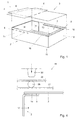
- Fig. 1 shows, in perspective view, a package 1 according to the invention, comprising a tray-shaped box 2 and a film 3 which, by way of closure, can be attached against the box 2.
- the tray-shaped box 2 comprises a substantially rectangular bottom 10, bound by four upstanding walls 11- 14, which are mutually connected by glue flaps 15, 115 and jointly bound an open filling side 7.
- the edges 16 of the upstanding walls 11- 14 remote from the bottom 10 can be folded inwards over approximately 90°, so that they extend approximately parallel to the bottom 10, as shown on the right hand side in Fig. 1.
- the edges 16 can partly overlap, be shortened or mitred so that they abut against each other in a virtually flat manner.
- These edges can be glued, with glue flaps provided on both sides, against an inside or outside of the adjacent, "edgeless" sidewalls.
- the film 3 can substantially correspond to that of the bottom 10, as shown on the right hand side in Fig. 1.
- the film 3 can be sealed onto the folded-in upper edges 16 of the box 2, which edges 16 can be provided to that end with a thermoplastic coating 8, indicated in hatching in Fig. 1.
- the film 3 can be provided with edges 6 as shown on the left hand side in Fig. 1. With this, the film 3 can be sealed against the upstanding sidewalls 11- 14, on a coating layer 8 especially provided thereto, as indicated in hatching.
- the film 3 can have other forms and dimensions.
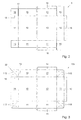
- Figs. 2 and 3 show two blanks 5, 105, respectively, from which a box 2 according to Fig. 1 can be set up, while on the left hand side, each time, a blank half is shown for a box 2 without upper edges 16 (corresponding to the left hand box half of Fig. 1) and, on the right hand side, a blank half for a box 2 with upper edges 16.
- Both blanks 5, 105 are manufactured from cardboard, for instance solid cardboard or corrugated cardboard, while, on a side turned inwards in set-up condition, at least the bottom 10, the side walls 11- 14 and the glue flaps 15, 115 are provided with a moisture-proof plastic coating 8.
- a plastic which is highly suitable to that end from a price-performance point of view is, for instance, Polyethylene (PE).
- Other suitable coating materials are for instance Polypropylene (PP), aluminum (which can be glued as a film on the cardboard blank), wax or two-component coatings.
- thermoplastic plastic for the purpose of sealing the film 3 thereon.
- Suitable thermoplastic plastics are, for instance, Polyethylene (PE), once more due to the favorable price-performance ratio, Polypropylene (PP) or SIRLIN coatings.
- the blanks 5, 105 can also be coated completely two-sidedly.
- the coating 8 can be applied to the cardboard as, for instance, pre-formed film, or be sprayed on in melted form or powder form, or be applied to the cardboard with a doctor blade. This can moreover be done before of after the blank 5, 105 is punched out.
- the thickness of the coating 8 is as thin as possible. This is favorable to the cost price and for recycling, at least with two-sidedly coated blanks. These are ground in a pulverizer. A thin coating layer will then break up more rapidly so that released paper fibers can dissolve in water. One-sidedly coated blanks are re-processed differently. In that case, a slightly thicker coating layer can be advantageous because this can be separated in a simpler manner.
- the minimal possible coating thickness depends, inter alia, on the coating material used, the manner of application used and the surface roughness of the base (the cardboard or, optionally, a paper intermediate layer). When this roughness is great, and consequently, the cardboard or paper fibers project far, no sufficiently continuous layer can be obtained. When using a reasonable paper quality, the thickness of the Polyethylene coating can be around, for instance, 15 ⁇ m.
- the two blanks 5, 105 differ mainly as to glue flaps 15, 115 with which the box walls 11- 14 are mutually connected in set-up condition.
- blank 5 (Fig. 2) via a first folding line 18, these glue flaps 15 are pivotally connected to one adjacent sidewall 12, 14, and via an incision 17, separated from the other adjacent sidewall 11, 13.
- blank 105 (Fig. 3) the glue flaps 115 are connected to both adjacent sidewalls, via respective first and second folding lines 18, 19.
- the glue flaps 115 further comprise a third folding line 20, which extends from a corner point adjacent the bottom 10 to a corner point of the glue flap 115 located diagonally opposite thereto.
- the film 3 can be sealed to the inside of the box walls 11, 14 with the aid of known sealing devices, while the outsides of these walls are to be supported temporarily to absorb the great forces that are applied when sealing.
- the film 3 can also be sealed against an outside of the box 2 without additional support means, for instance to the edges 16 as shown in Fig. 4, with the aid of a special sealing device 25 according to the invention.
- FIG. 4 schematically shows a possible embodiment of such a sealing device 25, comprising an elongated, flexible heating element 26, for instance an electric wire or heat conductive strip, flexibly suspended so that bending or deformation of the element 26 in the direction of the sealing base (box edge 16) is possible but lateral displacement (substantially parallel to the box edge 16) is not possible.
- this is realized by suspending the heating element 26 between two layers of film 27, 28.
- other embodiments are possible too.
- the device 25 further comprises press-on means 30, for pressing the heating element 26 against the sealing base.
- press-on means 30 too are of flexible design, such that they can follow possible irregularities in the sealing base and deformations of the heating element 26 as a result thereof.
- the press-on means can for instance be manufactured from rubber, with a relatively low Shore hardness, or be formed from a flexible tube filled with a pressure medium, for instance air or liquid.
- the film layers 27, 28 are provided, at their sides remote from the heating element 26, with a non-stick layer, for instance of Teflon, so that, in use, they do not stick to the film 3 to be sealed, or the press-on means 30, respectively.
- a non-stick layer for instance of Teflon
- the heating element 26 itself can be covered in such a non-stick layer.
- the material and the thickness of the film layer 27 proximal to the sealing base is preferably selected such that it disturbs the heat transfer of the heating element 26 as little as possible while, conversely, the material and the thickness of the other film layer 28 is selected such that heat transfer to the press-on means 30 is limited to a minimum.
- sealing device 25 With the above-described sealing device 25, relatively good sealing seams can be effected, i.e. with a high sealing capacity on a relatively unstable, irregular sealing bases such as a box wall.
- This can be understood as follows. Due to the flexibility of the heating element 26, this element can abut well against the sealing base and any irregularities therein without great forces being required thereto. Due to the flexible press-on means 30, furthermore, a uniformly distributed press-on force can be applied to this heating element 26, which press-on force needs not be high and is free of pressure peaks that occur in customary sealing devices at the location of irregularities in the sealing base.
- sealing seams can be realized on a box wall as shown, with press-on forces between approximately 0.02 and 0.5 N/mm 2 , with the press-on force used depending on, inter alia, the thickness and type of material of the film layers to be sealed together.
- the thus realized sealing seams are of good quality, with a high degree of moisture-tightness, at least a high moisture barrier. Overall, it holds here that the quality, in particular the sealing action of the sealing seam will be better as the sealing base on which the sealing seams have been realized has fewer irregularities.
- the tray-shaped box may have a triangular, square or multi-angular bottom surface, surrounded by a corresponding number of upstanding walls.
- the box may further be divided into several compartments by means of horizontal or vertical partitions.
- parts of the box can be designed to be transparent, so that the content is visible.
- the blank can for instance be provided with openings covered with transparent film.
- the boxes can be designed as ready-for-use carton, which are glued together in a factory and are then, in flat condition, taken to a location of use where they can be set up without further gluing operations.
- the blank can be coated with two different types of plastic, while the one coating can have good moisture-proof properties and the other coating can have good sealing properties.
Abstract
- manufacturing a cardboard blank which is provided, at least partly, with a plastic coating;
- setting up the blank into a substantially tray-shaped box (2);
- filling the box with products to be packaged;
Description
- The invention relates to a method for realizing a package, more in particular a package for deep-frozen or moist products such as meats, fish vegetables or the like.
- As a rule, such products are packaged in a cardboard box which, prior to filling, is lined with a moisture-proof film, which can then be wrapped around the products. The box is closed off by a cardboard lid. This manner of packaging offers the advantage that the cardboard boxes can be printed, and contribute to a high-quality effect of the product packaged therein. However, a drawback is that the manner of packaging uses up relatively much material and is labour intensive and difficult to automate, in particular the application of the film.
- Further, a manner of packaging is known, used in particular for packaging fish, with which bags are formed from film webs which, after filling, are sealed tight and are placed into a plastic crate whereupon, optionally, the content can frozen. An advantage of this manner of packaging is that the process can be automated well and that relatively little packaging material is used up, since the crates are re-usable. However, a drawback is that as a rule, bags give a somewhat cheap impression, which may have an effect on the products packaged in these bags. Furthermore, the bags are difficult to open and can easily become damaged during transport, so that products become lost and the surroundings may become dirty. Further, the crates are to be cleaned before they are reused, which is labour intensive and a burden to the environment.
- The invention contemplates providing a method of the type described hereinabove, wherein the drawbacks of the known manners of packaging are at least partly avoided while the advantages thereof are maintained. In particular, the invention contemplates providing a less labour intensive manner of packaging, which can easily be automated and with which relatively little packaging material is used up. To that end, a method according to the invention is characterized by the features of
claim 1. - By providing a cardboard blank with a suitable coating, a moisture-proof box can be obtained without the time-consuming and hard-to-automate operations of lining, tightening and pressing-on a film in the set-up box. Such a coating can be applied to the blank before or after is has been punched out, in a simple manner with relatively uncomplicated machines. The coating layer can, furthermore, be applied such that, after use, it can be separated from the blank in a simple manner, for separate waste disposal.
- By closing off the box with a layer of film instead of with a lid, packaging material can be economized on. This is favorable for the environment (less waste material) and, furthermore, is advantageous as to packaging weight, volume and associated costs. The closing film can moreover be designed to be transparent, so that the content remains visible to inspection, without, to that end, the package having to be opened. As an alternative, like the cardboard, the film can be printed on, at least partly. With the film, furthermore, a good closure can be effected. To that end, the film can be attached to a coated part of the box by heat welding or ultrasonic welding, with the film locally fusing with the coating. Thus, with a few welded spots, which can be easily automated, the film can be prevented from coming loose inadvertently or be opened without anyone noticing. In order to open the package at the destination, the film can simply be torn loose, for instance by a tear lip provided to that end. Alternatively, the film can, for instance, be cut open or torn open along weakening lines provided thereto.
- In an advantageous embodiment, a method according to the invention is characterized by the features of
claim 2. - By setting up the box from a continuous blank, i.e. without incisions or notches between adjacent bottom and/or wall forming parts, a tray-shaped box can be obtained without splits or cracks. By, furthermore, providing this continuous blank with a moisture repelling coating, at least on a side turned inwards in set-up condition, a leak-proof box can be obtained, suitable to receive "moist" products such as deep-frozen goods or goods still to be frozen, in particular meat, fish or vegetables.
- Thereupon, this leak-proof box can be closed off by sealing the closing film to the box, with a continuous, substantially moisture-tight sealing seam closed in itself, according to the features of
claim 3. Thus, with minimal and, what is more, easy-to-automate packaging operations, and a minimum of packaging material, a substantially moisture-tight package can be obtained which is suitable for transport and storage of the above-mentioned goods, and can easily be opened after use. - In a particularly advantageous embodiment, a method according to the invention is characterized by the features of claim 4.
- Through the use of a flexible heating element, which can follow irregularities in the base and/or film to be sealed and hence can close-fittingly abut against said film material, a good, that is to say substantially moisture-tight sealing seam of good quality can be realized without, to that end, high press-on forces being required. As a result thereof, this sealing method is not limited to use on flat, very solid sealing bases, such as an anvil which is usually deployed to that end, but the sealing method can be advantageously used on a much less solid and less flat base, such as a wall of the box itself, without this wall requiring special reinforcements or external support. Consequently, a very great freedom as to the placement of the sealing seams is obtained.
- In a particularly advantageous embodiment, the film is sealed such that its edges to not project relative to the contour of the box, as defined by its ribs. Such projecting film edges are inevitably formed with known sealing methods as the sealing seams are effected outside the contour of the box, on an anvil, and can cause a lot of nuisance because during transport and storage, these edges can become trapped between stacked boxes. With a method according to the invention, these problems can be effectively avoided by sealing the film against the box walls, for instance against the outside of the upstanding walls or on upper edges folded inwards. Naturally, blank parts corresponding to these sealing locations can, prior to setting up, be provided with a suitable thermoplastic coating.
- It is preferred that the box is free of sharp edges or sudden transitions, at least at the location where the film is sealed, according to the features of
claim 8. As a result, the quality of the sealing seams provided thereon can be even better, in terms of sealing capacity and moisture tightness. - The invention further relates to a box according to the features of
claim 10 and a blank according toclaim 17, for use in a method according to the invention. By setting up the box from a continuous cardboard blank, which is free of incisions and is provided on desired locations with a plastic, at least water repelling coating, in a very simple manner, a leak proof box can be obtained, suitable for packaging moist products, such as deep-frozen goods, which can, furthermore, be closed off well with a length of plastic film that can be sealed to the box. The plastic coating on the inside of the box can for instance be formed by a layer of non-corona treated polyethylene. As a rule, such coating material is supplied with a Corona treatment, in order to render the coating printable. However, due to a non-Corona design according to the invention, in an advantageous manner, products that are frozen in the boxes, are prevented from freezing to the coating material. - The invention further relates to a device according to the features of
claim 18, for sealing the film onto a relatively weak, not entirely flat sealing base, such as the cardboard wall of a box. As the heating element is flexible, this can close-fittingly follow differences in height in the sealing base and/or film and, as a result, each time abut well against the film to be sealed, without, thereto, great press-on forces being required, so that a good sealing sealing seam can be effected. - In the further subclaims, further advantageous embodiments of a method, box, blank and device according to the invention are described.
- In clarification of the invention, exemplary embodiments of a blank, box and method of packaging will be further elucidated with reference to the drawing. In the drawing:
- Fig. 1 shows a package according to the invention, composed of a tray-shaped box and a sheet of film material which, by way of closure, can be attached over the open side of the box;
- Fig. 2 shows a first embodiment of a possible blank on which the box of Fig. 1 is based;
- Fig. 3 shows an alternative embodiment of blank on which the box of Fig. 1 is based; and
- Fig. 4 schematically shows a sealing device according to the invention, for sealing the film material to the box.
-
- Fig. 1 shows, in perspective view, a
package 1 according to the invention, comprising a tray-shaped box 2 and afilm 3 which, by way of closure, can be attached against thebox 2. - The tray-
shaped box 2 comprises a substantiallyrectangular bottom 10, bound by four upstanding walls 11- 14, which are mutually connected byglue flaps edges 16 of the upstanding walls 11- 14 remote from thebottom 10 can be folded inwards over approximately 90°, so that they extend approximately parallel to thebottom 10, as shown on the right hand side in Fig. 1. Here, at the location of the corner points, theedges 16 can partly overlap, be shortened or mitred so that they abut against each other in a virtually flat manner. Further, it is possible to provide only two opposite walls with such anedge 16. These edges can be glued, with glue flaps provided on both sides, against an inside or outside of the adjacent, "edgeless" sidewalls. - As to shape and dimensions, the
film 3 can substantially correspond to that of thebottom 10, as shown on the right hand side in Fig. 1. In that case, in a manner to be described further, thefilm 3 can be sealed onto the folded-inupper edges 16 of thebox 2, whichedges 16 can be provided to that end with athermoplastic coating 8, indicated in hatching in Fig. 1. Alternatively, thefilm 3 can be provided withedges 6 as shown on the left hand side in Fig. 1. With this, thefilm 3 can be sealed against the upstanding sidewalls 11- 14, on acoating layer 8 especially provided thereto, as indicated in hatching. Naturally, thefilm 3 can have other forms and dimensions. - Figs. 2 and 3 show two
blanks box 2 according to Fig. 1 can be set up, while on the left hand side, each time, a blank half is shown for abox 2 without upper edges 16 (corresponding to the left hand box half of Fig. 1) and, on the right hand side, a blank half for abox 2 withupper edges 16. Bothblanks plastic coating 8. A plastic which is highly suitable to that end from a price-performance point of view is, for instance, Polyethylene (PE). Other suitable coating materials are for instance Polypropylene (PP), aluminum (which can be glued as a film on the cardboard blank), wax or two-component coatings. - Further, at least a part of the side of the blank 5, 105 facing outward in set-up condition is coated with a thermoplastic plastic for the purpose of sealing the
film 3 thereon. Suitable thermoplastic plastics are, for instance, Polyethylene (PE), once more due to the favorable price-performance ratio, Polypropylene (PP) or SIRLIN coatings. Naturally, theblanks coating 8 can be applied to the cardboard as, for instance, pre-formed film, or be sprayed on in melted form or powder form, or be applied to the cardboard with a doctor blade. This can moreover be done before of after the blank 5, 105 is punched out. - It is preferred that the thickness of the
coating 8 is as thin as possible. This is favorable to the cost price and for recycling, at least with two-sidedly coated blanks. These are ground in a pulverizer. A thin coating layer will then break up more rapidly so that released paper fibers can dissolve in water. One-sidedly coated blanks are re-processed differently. In that case, a slightly thicker coating layer can be advantageous because this can be separated in a simpler manner. The minimal possible coating thickness depends, inter alia, on the coating material used, the manner of application used and the surface roughness of the base (the cardboard or, optionally, a paper intermediate layer). When this roughness is great, and consequently, the cardboard or paper fibers project far, no sufficiently continuous layer can be obtained. When using a reasonable paper quality, the thickness of the Polyethylene coating can be around, for instance, 15 µm. - The two
blanks first folding line 18, these glue flaps 15 are pivotally connected to oneadjacent sidewall incision 17, separated from the otheradjacent sidewall second folding lines third folding line 20, which extends from a corner point adjacent the bottom 10 to a corner point of theglue flap 115 located diagonally opposite thereto. In the set-up condition, theglue flap 115 is folded around this diagonal folding line, with the outer sides against each other so that atriangular glue flap 115 is obtained which is glued against an inside of one of the adjacent box walls 11-14. An advantage of this second embodiment is that thebox 2 set-up therefrom is free of splits, cracks or similar openings and hence, in combination with thecoating 8, yields a leak-proof box 2, suitable for transport of moist or deep-frozen products such as meat, fish, vegetables. - After the products have been provided in the
box 2, it can be closed off with the earlier-mentionedfilm 3. Thefilm 3 can be sealed to the inside of thebox walls film 3 can also be sealed against an outside of thebox 2 without additional support means, for instance to theedges 16 as shown in Fig. 4, with the aid of aspecial sealing device 25 according to the invention. - Fig. 4 schematically shows a possible embodiment of such a
sealing device 25, comprising an elongated,flexible heating element 26, for instance an electric wire or heat conductive strip, flexibly suspended so that bending or deformation of theelement 26 in the direction of the sealing base (box edge 16) is possible but lateral displacement (substantially parallel to the box edge 16) is not possible. In the example shown, this is realized by suspending theheating element 26 between two layers offilm - The
device 25 further comprises press-onmeans 30, for pressing theheating element 26 against the sealing base. These press-onmeans 30 too are of flexible design, such that they can follow possible irregularities in the sealing base and deformations of theheating element 26 as a result thereof. To that end, the press-on means can for instance be manufactured from rubber, with a relatively low Shore hardness, or be formed from a flexible tube filled with a pressure medium, for instance air or liquid. - Preferably, the film layers 27, 28 are provided, at their sides remote from the
heating element 26, with a non-stick layer, for instance of Teflon, so that, in use, they do not stick to thefilm 3 to be sealed, or the press-onmeans 30, respectively. Naturally, in the absence of the film layers 27, 28, also theheating element 26 itself can be covered in such a non-stick layer. The material and the thickness of thefilm layer 27 proximal to the sealing base is preferably selected such that it disturbs the heat transfer of theheating element 26 as little as possible while, conversely, the material and the thickness of theother film layer 28 is selected such that heat transfer to the press-onmeans 30 is limited to a minimum. - With the above-described
sealing device 25, relatively good sealing seams can be effected, i.e. with a high sealing capacity on a relatively unstable, irregular sealing bases such as a box wall. This can be understood as follows. Due to the flexibility of theheating element 26, this element can abut well against the sealing base and any irregularities therein without great forces being required thereto. Due to the flexible press-onmeans 30, furthermore, a uniformly distributed press-on force can be applied to thisheating element 26, which press-on force needs not be high and is free of pressure peaks that occur in customary sealing devices at the location of irregularities in the sealing base. - Owing to the proper abutment of the
heating element 26, heat, given off by theelement 26 will be uniformly spread over theunderlying film 3 andcoating 8 so that, also under the influence of the press-on force, these layers fuse into a regular sealing seam. - From tests carried out by applicant it appears that in the above-mentioned manner, sealing seams can be realized on a box wall as shown, with press-on forces between approximately 0.02 and 0.5 N/mm2, with the press-on force used depending on, inter alia, the thickness and type of material of the film layers to be sealed together. The thus realized sealing seams are of good quality, with a high degree of moisture-tightness, at least a high moisture barrier. Overall, it holds here that the quality, in particular the sealing action of the sealing seam will be better as the sealing base on which the sealing seams have been realized has fewer irregularities.
- The invention is not limited in any manner to the exemplary embodiments represented in the description and the drawing. Also combinations of (parts of) exemplary embodiments shown are understood to fall within the inventive concept. Moreover, many variants are possible within the framework of the invention as outlined by the claims.
- For instance, the tray-shaped box may have a triangular, square or multi-angular bottom surface, surrounded by a corresponding number of upstanding walls. The box may further be divided into several compartments by means of horizontal or vertical partitions. If desired, parts of the box can be designed to be transparent, so that the content is visible. To that end, the blank can for instance be provided with openings covered with transparent film. Further, the boxes can be designed as ready-for-use carton, which are glued together in a factory and are then, in flat condition, taken to a location of use where they can be set up without further gluing operations. To that end, with the box shown, only the two opposite sidewalls against which the glue flaps 15,115 have been glued need each to be provided with two additional folding lines, which extend from the bottom corner points diagonally upwards to the upper edge, at an angle of approximately 45 degrees. In that case, the glue flaps 15, 115 need only be glued against the triangular corner parts of the sidewall on both sides of the additional folding lines.
- The blank can be coated with two different types of plastic, while the one coating can have good moisture-proof properties and the other coating can have good sealing properties.
- These and many variations are understood to fall within the framework of the invention as set forth in the following claims.
Claims (18)
- A method for realizing a package (1), comprising the steps of:manufacturing a cardboard blank (5, 105) which is provided, at least partly, with a plastic coating (8);setting up the blank (5, 105) into a substantially tray-shaped box (2);filling the box (2) with products to be packaged;closing off the box with a plastic film (3) and sealing this film (3) against a coated part of the box (2).
- A method according to claim 1 for packaging moist or deep-frozen products such as meats, fish, vegetables or the like, wherein the tray-shaped box (2), at least a bottom (10) and upstanding sidewalls (11 - 14) thereof, is set-up from a continuous blank part, free of incisions or notches, and the coating (8) is applied such that, in set-up condition, it covers at least the inside of the tray-shaped box (2), the arrangement being such that a substantially leak-proof box (2) is obtained.
- A method according to claim 1 or 2, wherein the film (3) is attached to the box (2) with a continuous, substantially moisture-tight sealing seam closed in itself.
- A method according to any one of the preceding claims, wherein the film (3) is attached through heat sealing, while a flexible heating element (26) is pressed against the film (3) with flexible press-on means (30) such that the heating element (26) close-fittingly abuts over approximately its entire length against the film (3) and, under the influence of heat and the applied press-on force, the film fuses with the underlying coating (8).
- A method according to claim 4, wherein the press-on forces applied during sealing are lower than 0.5 N/mm2, in particular lower than 0.1 N/mm2, and preferably around approximately 0.02 to 0.05 N/mm2.
- A method according to any one of the preceding claims, wherein the film (3) in sealed condition is located within, or substantially corresponds to an outer contour defined by the ribs of the tray-shaped box (2).
- A method according to any one of the preceding claims, wherein the film (3) is sealed against the outside of the box (2).
- A method according to any one of the preceding claims, wherein the blank (5, 105) and the box (2) set-up therefrom are designed such that adjacent walls (11 - 14) or wall parts seamlessly link up with each other, at least at the location where the film (3) is sealed.
- A method according to any one of the preceding claims, wherein the edges (16) of the box walls (11 - 14) extending around an open filling side (7) of the box (2) are folded inwards, and the film (3) is sealed onto these edges (16).
- A box (2) for use in a method according to any one of the preceding claims, comprising a bottom (10) and upstanding walls (11 - 14) surrounding this bottom (10) with edges (16) remote from the bottom (10) and folded inwards, which surround an open filling side (7) and extend substantially parallel to the bottom (10), wherein the box (2) is set-up from a cardboard blank (5, 105) provided with a plastic coating (8) which covers at least the bottom (1) and the upstanding walls (11 - 14) on a side turned inward in set-up condition.
- A box (2) according to claim 10, wherein the bottom (10) and the upstanding walls (11 - 14) are set up from one continuous blank part, free of incisions or other types of openings, while forming a crack-free, substantially leak-proof tray.
- A box (2) according to claims 10 or 11, wherein, on a side turned inwards in set-up condition, the blank is provided with a Polyethylene non-Corona coating.
- A box (2) according to any one of claims 10 - 12, wherein the blank is manufactured from a cardboard thickness of approximately 750 and 1000 gr/m2.
- A box (2) according to any one of claims 10 - 13, wherein the folded-in edges (16) have a width of approximately 40 mm.
- A box (2) according to any one of claims 10 - 14, wherein the box has a length of 590 mm, a width of 390 mm and a height of 115 mm.
- A box (2) according to any one of claims 10 - 15, wherein the box (2) is closed off by a thermoplastic film (3) which is sealed on a coated part of the box (2), preferably on the edges (16) surrounding the filling side (7).
- A blank (5, 105) comprising the features of a blank for use in a method according to any one of claims 1 - 9, for setting up a box (2) therefrom according to any one of claims 10 - 16.
- A device (25) for sealing film (3) on a relatively weak base such as a cardboard box wall, comprising a flexible heating element (26) and flexible press-on means (30) designed to close-fittingly follow differences in height in a sealing base.
Applications Claiming Priority (2)
| Application Number | Priority Date | Filing Date | Title |
|---|---|---|---|
| NL1026382 | 2004-06-10 | ||
| NL1026382A NL1026382C2 (en) | 2004-06-10 | 2004-06-10 | Method, box, blank and sealing device for the realization of a package. |
Publications (2)
| Publication Number | Publication Date |
|---|---|
| EP1607337A2 true EP1607337A2 (en) | 2005-12-21 |
| EP1607337A3 EP1607337A3 (en) | 2006-01-04 |
Family
ID=34974086
Family Applications (1)
| Application Number | Title | Priority Date | Filing Date |
|---|---|---|---|
| EP05076367A Withdrawn EP1607337A3 (en) | 2004-06-10 | 2005-06-10 | Carton box, blank, method for manufacturing said box |
Country Status (3)
| Country | Link |
|---|---|
| EP (1) | EP1607337A3 (en) |
| NL (1) | NL1026382C2 (en) |
| NO (1) | NO20052819L (en) |
Cited By (1)
| Publication number | Priority date | Publication date | Assignee | Title |
|---|---|---|---|---|
| WO2011083342A3 (en) * | 2010-01-08 | 2011-11-17 | Linpac Packaging Limited | Sealable container, sealed container and processes for making a sealable container and a sealed container |
Citations (6)
| Publication number | Priority date | Publication date | Assignee | Title |
|---|---|---|---|---|
| US2940654A (en) * | 1958-09-18 | 1960-06-14 | Pillsbury Co | Container |
| US3387427A (en) * | 1963-05-10 | 1968-06-11 | Grace W R & Co | Method of forming a carton enclosed package from a preformed foldable blank |
| FR2481677A1 (en) * | 1980-05-01 | 1981-11-06 | Metal Box Co Ltd | CONTAINERS AND METHOD FOR PACKAGING FOOD |
| EP0373907A1 (en) * | 1988-12-14 | 1990-06-20 | Du Pont Canada Inc. | Heat-sealing device for thermoplastic films |
| EP0899379A2 (en) * | 1997-08-25 | 1999-03-03 | Westvaco Corporation | Heat sealed, ovenable food cartons and lids |
| EP1170220A1 (en) * | 2000-07-06 | 2002-01-09 | Suzuki Manufacturing, Ltd. | Foldable carton tray |
-
2004
- 2004-06-10 NL NL1026382A patent/NL1026382C2/en not_active IP Right Cessation
-
2005
- 2005-06-10 NO NO20052819A patent/NO20052819L/en not_active Application Discontinuation
- 2005-06-10 EP EP05076367A patent/EP1607337A3/en not_active Withdrawn
Patent Citations (6)
| Publication number | Priority date | Publication date | Assignee | Title |
|---|---|---|---|---|
| US2940654A (en) * | 1958-09-18 | 1960-06-14 | Pillsbury Co | Container |
| US3387427A (en) * | 1963-05-10 | 1968-06-11 | Grace W R & Co | Method of forming a carton enclosed package from a preformed foldable blank |
| FR2481677A1 (en) * | 1980-05-01 | 1981-11-06 | Metal Box Co Ltd | CONTAINERS AND METHOD FOR PACKAGING FOOD |
| EP0373907A1 (en) * | 1988-12-14 | 1990-06-20 | Du Pont Canada Inc. | Heat-sealing device for thermoplastic films |
| EP0899379A2 (en) * | 1997-08-25 | 1999-03-03 | Westvaco Corporation | Heat sealed, ovenable food cartons and lids |
| EP1170220A1 (en) * | 2000-07-06 | 2002-01-09 | Suzuki Manufacturing, Ltd. | Foldable carton tray |
Cited By (4)
| Publication number | Priority date | Publication date | Assignee | Title |
|---|---|---|---|---|
| WO2011083342A3 (en) * | 2010-01-08 | 2011-11-17 | Linpac Packaging Limited | Sealable container, sealed container and processes for making a sealable container and a sealed container |
| EP2845819A1 (en) * | 2010-01-08 | 2015-03-11 | Linpac Packaging Limited | Sealable container and processes for making a sealable container and a sealed container |
| EP3184453A1 (en) * | 2010-01-08 | 2017-06-28 | LINPAC Packaging Limited | Sealable container, sealed container and processes for making thereof |
| EP3184453B1 (en) | 2010-01-08 | 2022-03-09 | LINPAC Packaging Limited | Sealable container, sealed container and processes for making thereof |
Also Published As
| Publication number | Publication date |
|---|---|
| NO20052819D0 (en) | 2005-06-10 |
| NO20052819L (en) | 2005-12-12 |
| EP1607337A3 (en) | 2006-01-04 |
| NL1026382C2 (en) | 2005-12-14 |
Similar Documents
| Publication | Publication Date | Title |
|---|---|---|
| EP2361847B1 (en) | Container being provided with an inner bag | |
| US7938312B2 (en) | Carton with bag closures | |
| US11072444B2 (en) | Method of producing and filling a packaging container | |
| WO2009153558A1 (en) | Container | |
| US7097092B1 (en) | Package for food products | |
| US6082614A (en) | Package for pourable goods | |
| US20220055789A1 (en) | Product package and method of manufacturing the same as well as package blank | |
| US20110065557A1 (en) | Carton assembly having a waterproof lining | |
| CA3099463A1 (en) | Flexible membrane with valve | |
| US20220363427A1 (en) | Method of Producing a Packaging Container and a Packaging Container | |
| EP1607337A2 (en) | Carton box, blank, method for manufacturing said box | |
| AU2012211504A1 (en) | Container being provided with an inner bag | |
| US20220267061A1 (en) | Sealing Disc For Paperboard Container And A Packaging Container Comprising The Sealing Disc | |
| RU2781085C2 (en) | Bag-type flexible packaging with reclosing device | |
| RU2622781C2 (en) | Closure on a rectangular container | |
| EP0628485A1 (en) | Liquid tight package having upper and lower lid parts | |
| DK2599724T3 (en) | Folding Carton for rod-shaped frozen-food and other frozen foods | |
| GB2314553A (en) | Display sack with removable panel | |
| JP2023501427A (en) | Packing container including container body and internal sealing member |
Legal Events
| Date | Code | Title | Description |
|---|---|---|---|
| PUAI | Public reference made under article 153(3) epc to a published international application that has entered the european phase |
Free format text: ORIGINAL CODE: 0009012 |
|
| PUAL | Search report despatched |
Free format text: ORIGINAL CODE: 0009013 |
|
| AK | Designated contracting states |
Kind code of ref document: A2 Designated state(s): AT BE BG CH CY CZ DE DK EE ES FI FR GB GR HU IE IS IT LI LT LU MC NL PL PT RO SE SI SK TR |
|
| AX | Request for extension of the european patent |
Extension state: AL BA HR LV MK YU |
|
| AK | Designated contracting states |
Kind code of ref document: A3 Designated state(s): AT BE BG CH CY CZ DE DK EE ES FI FR GB GR HU IE IS IT LI LT LU MC NL PL PT RO SE SI SK TR |
|
| AX | Request for extension of the european patent |
Extension state: AL BA HR LV MK YU |
|
| RAP1 | Party data changed (applicant data changed or rights of an application transferred) |
Owner name: KAPPA "GSF" B.V. |
|
| 17P | Request for examination filed |
Effective date: 20060630 |
|
| AKX | Designation fees paid |
Designated state(s): AT BE BG CH CY CZ DE DK EE ES FI FR GB GR HU IE IS IT LI LT LU MC NL PL PT RO SE SI SK TR |
|
| RAP1 | Party data changed (applicant data changed or rights of an application transferred) |
Owner name: SMURFIT KAPPA GSF B.V. |
|
| STAA | Information on the status of an ep patent application or granted ep patent |
Free format text: STATUS: THE APPLICATION IS DEEMED TO BE WITHDRAWN |
|
| 18D | Application deemed to be withdrawn |
Effective date: 20080103 |