EP1607321A2 - Bicycle control apparatus - Google Patents
Bicycle control apparatus Download PDFInfo
- Publication number
- EP1607321A2 EP1607321A2 EP05012545A EP05012545A EP1607321A2 EP 1607321 A2 EP1607321 A2 EP 1607321A2 EP 05012545 A EP05012545 A EP 05012545A EP 05012545 A EP05012545 A EP 05012545A EP 1607321 A2 EP1607321 A2 EP 1607321A2
- Authority
- EP
- European Patent Office
- Prior art keywords
- bicycle
- seat
- post
- mounting
- control unit
- Prior art date
- Legal status (The legal status is an assumption and is not a legal conclusion. Google has not performed a legal analysis and makes no representation as to the accuracy of the status listed.)
- Granted
Links
Images





Classifications
-
- B—PERFORMING OPERATIONS; TRANSPORTING
- B62—LAND VEHICLES FOR TRAVELLING OTHERWISE THAN ON RAILS
- B62M—RIDER PROPULSION OF WHEELED VEHICLES OR SLEDGES; POWERED PROPULSION OF SLEDGES OR SINGLE-TRACK CYCLES; TRANSMISSIONS SPECIALLY ADAPTED FOR SUCH VEHICLES
- B62M25/00—Actuators for gearing speed-change mechanisms specially adapted for cycles
- B62M25/08—Actuators for gearing speed-change mechanisms specially adapted for cycles with electrical or fluid transmitting systems
-
- B—PERFORMING OPERATIONS; TRANSPORTING
- B62—LAND VEHICLES FOR TRAVELLING OTHERWISE THAN ON RAILS
- B62J—CYCLE SADDLES OR SEATS; AUXILIARY DEVICES OR ACCESSORIES SPECIALLY ADAPTED TO CYCLES AND NOT OTHERWISE PROVIDED FOR, e.g. ARTICLE CARRIERS OR CYCLE PROTECTORS
- B62J11/00—Supporting arrangements specially adapted for fastening specific devices to cycles, e.g. supports for attaching maps
-
- B—PERFORMING OPERATIONS; TRANSPORTING
- B62—LAND VEHICLES FOR TRAVELLING OTHERWISE THAN ON RAILS
- B62J—CYCLE SADDLES OR SEATS; AUXILIARY DEVICES OR ACCESSORIES SPECIALLY ADAPTED TO CYCLES AND NOT OTHERWISE PROVIDED FOR, e.g. ARTICLE CARRIERS OR CYCLE PROTECTORS
- B62J45/00—Electrical equipment arrangements specially adapted for use as accessories on cycles, not otherwise provided for
- B62J45/20—Cycle computers as cycle accessories
-
- B—PERFORMING OPERATIONS; TRANSPORTING
- B62—LAND VEHICLES FOR TRAVELLING OTHERWISE THAN ON RAILS
- B62K—CYCLES; CYCLE FRAMES; CYCLE STEERING DEVICES; RIDER-OPERATED TERMINAL CONTROLS SPECIALLY ADAPTED FOR CYCLES; CYCLE AXLE SUSPENSIONS; CYCLE SIDECARS, FORECARS, OR THE LIKE
- B62K19/00—Cycle frames
- B62K19/30—Frame parts shaped to receive other cycle parts or accessories
Definitions
- the present invention is directed to bicycles and, more particularly, to a bicycle control apparatus that may be mounted in the bicycle seat tube.
- Japanese Unexamined Patent Application No. 2004-247074 discloses a bicycle with an electronically controlled bicycle transmission.
- Conventional electronically controlled bicycle transmissions include an electronic drive mechanism such as a motor and deceleration mechanism that moves one or more of the transmission components.
- the transmission may be a derailleur or a hub transmission that includes an internal planetary gear mechanism.
- the electronic drive mechanism may be formed integrally with the electronically operated component, or it may be mounted to the bicycle frame separately from the electronically operated component.
- the control device used to control the operation of the electronically operated component also is mounted to the bicycle, typically on the handlebar together with a cycle computer.
- the mounting of the various electronic components on the bicycle tends to make the bicycle appear cluttered and visually unattractive. Furthermore, depending on where the electronic components are mounted, there is a risk that the components may obstruct steering. Sometimes the control device is integrated with a detachable cycle computer in an attempt to reduce the number of components mounted to the bicycle. However, then the electrically operated component cannot be operated when the cycle computer is detached or lost.
- a bicycle control apparatus comprises a mounting member and a control unit having a control signal output terminal that outputs an output control signal to operate a moving bicycle component.
- the control unit is disposed on the mounting member, and the mounting member and the control unit are dimensioned to fit within a seat tube of a bicycle. Additional inventive features will become apparent from the description below, and such features alone or in combination with the above features may form the basis of further inventions as recited in the claims and their equivalents.
- Fig. 1 is a side view of a particular embodiment of a bicycle
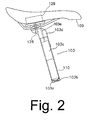
- Fig. 2 is a more detailed view of the seat assembly
- Fig. 3 is a front view of particular embodiments of brake lever assemblies mounted to the bicycle handlebar;
- Fig. 4 is an exploded cross sectional view of a particular embodiment of a seat post and an electronic component adapted to be mounted therein;
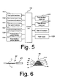
- Fig. 5 is a schematic block diagram of a particular embodiment of a derailleur control apparatus
- Fig. 6 is a schematic diagram of the front and rear sprocket assemblies
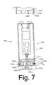
- Fig. 7 is an exploded cross sectional view of an alternative embodiment of a seat post and an electronic component adapted to be mounted therein;
- Fig. 8 shows an embodiment of wiring for electrical components mounted to the bicycle
- Fig. 9 is a schematic block diagram of another embodiment of a derailleur control apparatus that may be used with the hub dynamo shown in Fig. 8;
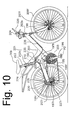
- Fig. 10 is a side view of another embodiment of a bicycle.
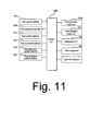
- Fig. 11 is a schematic block diagram of a particular embodiment of a suspension control apparatus used with the bicycle shown in Fig. 10.
- Fig. 1 is a side view of a bicycle 101 that includes particular embodiments of electrically operated components.
- Bicycle 101 is road bicycle comprising a diamond-shaped frame 102, a front fork 98 rotatably mounted to frame 102, a handlebar assembly 104 mounted to the upper part of fork 98, a front wheel 106f rotatably attached to the lower part of fork 98, a rear wheel 106r rotatably attached to the rear of frame 102, and a drive unit 105.
- a front wheel brake 107f is provided for braking front wheel 106f
- a rear wheel brake 107r is provided for braking rear wheel 106r.
- Drive unit 105 comprises a chain 95, a front sprocket assembly 99f coaxially mounted with a crank 96 having pedals PD, an electrically controlled front derailleur 97f attached to a seat tube 102a of frame 102, a rear sprocket assembly 99r coaxially mounted with rear wheel 106r, and an electrically controlled rear derailleur 97r.
- front sprocket assembly 99f comprises two coaxially mounted sprockets F1-F2
- rear sprocket assembly 99r comprises ten coaxially mounted sprockets R1-R10.
- the number of teeth on front sprocket F1 is less than the number of teeth on rear sprocket F2.
- Front derailleur 97f switches chain 95 between selected ones of the front sprockets F1-F2, and rear derailleur 97r switches chain 95 among selected ones of the rear sprockets R1-R10.
- Front derailleur 97f is driven by a front derailleur motor unit 127f (Fig. 5), and rear derailleur 97r is driven by a rear derailleur motor unit 127r.
- a front derailleur position sensor 133f senses the operating position of front derailleur 97f
- a rear derailleur position sensor 133r senses the operating position of rear derailleur 97r.
- a power supply 129 powers front and rear derailleur motor units 127f and 127r as well as other electrical components described herein.
- Power supply 129 may comprise a battery, a secondary power supply such as a large capacity capacitor, or some other power source.
- Handlebar assembly 104 comprises a handlebar stem 111 and a drop-style handlebar 112, wherein handlebar stem 111 is mounted to the upper part of fork 98, and handlebar 112 is mounted to the forward end portion of handlebar stem 111.
- brake lever assemblies 113f and 113r are mounted at opposite sides of handlebar 112.
- Brake lever assembly 113f controls the operation of front wheel brake 107f
- brake lever assembly 113r controls the operation of rear wheel brake 107r.
- a cycle computer 109 is mounted to a central portion of handlebar 112.
- Brake lever assemblies 113f and 113r comprise respective brake brackets 115f and 115r mounted to the forward curved portions of handlebar 112, and brake levers 116f and 116r pivotably mounted to brake brackets 115f and 115r.
- Front shift control devices 120f and 121f with switch levers 125 are mounted to the inner side of brake bracket 115f and to the rear side of brake lever 116f, respectively, to control the operation of front derailleur 97f.
- front shift control devices 120f and 121f independently control the operation of front derailleur 97f so that the rider may control the operation of front derailleur 97f with the hand grasping brake bracket 115f or with the hand grasping brake lever 116f.
- the switch lever 125 mounted to brake lever bracket 115f rotates downward from a home position P0 to a first position P1 and rotates upward from the home position P0 to a second position P2 to control the operation of front derailleur 97f.
- the switch lever 125 mounted to the rear of brake lever 116f rotates laterally inward from a home position P0 to a first position P1 and rotates laterally outward from the home position P0 to a second position P2 to control the operation of front derailleur 97f.
- independent rear shift control devices 120r and 121r with switch levers 125 are mounted to the inner side of brake bracket 115r and to the rear side of brake lever 116r, respectively, to control the operation of rear derailleur 97r.
- the switch levers 125 mounted to brake lever bracket 115r and brake lever 116r operate in the same manner as switch levers 125 mounted to brake lever bracket 115f and brake lever 116f. All of the switch levers 125 are biased toward the home position P0.
- a front upshift switch 131f (Fig. 5) and a front downshift switch 132f are mounted in each front shift control device 120f and 121f.
- the front upshift switches 131f operate when switch levers 125 in front shift control devices 120f and 121f rotate from position P0 to position P1
- the front downshift switches 132f operate when switch levers 125 in front shift control devices 120f and 121f rotate from position P0 to position P2.
- a rear upshift switch 131r and a rear downshift switch 132r are mounted in each rear shift control device 120r and 121r.
- the rear upshift switches 131r operate when switch levers 125 in rear shift control devices 120r and 121r rotate from position P0 to position P1
- the rear downshift switches 132r operate when switch levers 125 in rear shift control devices 120r and 121r rotate from position P0 to position P2.
- a seat post 103 is detachably mounted within seat tube 102a of frame 102.
- a saddle 109 is mounted to the top of seat post 103, and a derailleur control apparatus 110 is mounted within seat post 103 at a bottom portion thereof.
- Seat post 103 comprises a pipe member 103a dimensioned to fit within seat tube 102a, a circuit mounting structure 103b disposed at the bottom of pipe member 103a for mounting derailleur control apparatus 110, and a saddle mounting structure 103d disposed at the top of pipe member 103a for mounting saddle 109.
- circuit mounting structure 103b comprises a female threaded portion 103c formed on an inner peripheral surface of pipe member 103a
- saddle mounting structure 103d comprises a generally solid member that may be secured to pipe member 103a by welding or press fitting, for example.
- Saddle 109 may be fixed to saddle mounting member 103d by a bolt 128 or through some other means.
- an opening 103f is formed in a side wall of pipe member 103a for passing a signal input line 136b therethrough.
- Signal input line 136b communicates signals from front and rear upshift and downshift switches 131f, 132f, 131r and 132r to derailleur control apparatus 110, and it includes a detachable connector 136d.
- power supply 129 is mounted within saddle 109 to hide it from view and to locate it close to derailleur control apparatus 110.
- An opening 103e is formed in saddle mounting structure 103d for passing a power supply input line 136a therethrough.
- Power supply input line 136a supplies operating power to derailleur control apparatus, and it includes a detachable connector 136c.
- derailleur control apparatus 110 comprises a mounting member in the form of a housing 126 and a derailleur control unit 130 disposed within housing 126.
- Housing 126 comprises a tubular member 140 and a cover member 141, wherein housing 126 houses control unit 130, and cover member 141 is mounted to the lower end of tubular member 140.
- Tubular member 140 has an outer diameter slightly smaller than an inner diameter seat post 103 so that tubular member 140 fits within seat post 103.
- Tubular member 140 has an upper wall 140a on which is mounted an exposed power supply input terminal 134a and an exposed signal input terminal 134b for detachably connecting to connectors 136c and 136d of power supply input line 136a and signal input line 136b, respectively.
- a female threaded portion 140b is formed on the inner peripheral surface of a lower end of tubular member 140.
- Cover member 141 generally has the shape of a stepped bolt, and it comprises a head 141a, a post mounting structure in the form of a first male threaded portion 141b, and a second male threaded portion 141c.
- Head 141a has an outer diameter slightly smaller than an inner diameter of seat tube 102a
- first male threaded portion 141b has a diameter slightly smaller than the diameter of head 141a
- second male threaded portion 141c has a diameter slightly smaller than the diameter of first male threaded portion 141b.
- Second male threaded portion 141c is dimensioned to screw into female threaded portion 140b in tubular member 140 so that the abutment formed by the change in diameter between first male threaded portion 141b and second male threaded portion 141c abuts against the end face of tubular member 140.
- First male threaded portion 141b may be screwed into female threaded portion 103c in pipe member 103a of seat post 103 after cover member 141 is screwed into tubular member 140.
- the abutment formed by the change in diameter between head 141a and first male threaded portion 141b abuts against the end face of pipe member 103a, thereby mounting derailleur control apparatus 110 into seat post 103.
- a tool engaging structure 141d in the form of a pair of flats (only one flat is shown in Fig. 4) is formed on head 141a so that cover member 141 may be screwed into tubular member 140 and seat post 103 using an appropriate tool.
- An opening 141e is formed through head 141a for receiving front and rear signal wires 135f and 135r therethrough, wherein front and rear signal wires 135f and 135r have detachable connectors 135fc and 135rc at their corresponding ends.
- Front and rear signal wires 135f and 135r communicate signals from control unit 130 to front derailleur motor drive unit 127f and to rear derailleur motor unit 127r, respectively.
- Front and rear signal wires 135f and 135r also communicate signals from front and rear derailleur position sensors 133f and 133r to control unit 130.
- control unit 130 is a programmed microprocessor. As shown in Fig. 5, front derailleur motor unit 127f, rear derailleur motor unit 127r, power supply 129, front upshift switches 131f, front downshift switches 132f, rear upshift switches 131r, rear downshift switches 132r, front derailleur position sensor 133f, rear derailleur position sensor 133r and other I/O components are connected to control unit 130.
- Control unit 130 controls the operation of front derailleur 97f and rear derailleur 97r to shift chain 95 the distance from an origin sprocket to a destination sprocket in accordance with signals received from front and rear upshift switches 131f and 131r, front and rear downshift switches 132f and 132r, and front and rear derailleur position sensors 133f and 133r.
- cover member 141 is tightly screwed into tubular member 140 using second male threaded portion 141c in cover member 141 and female threaded portion 140b in tubular member 140.
- connector 136c of power supply input line 136a and connector 136d of signal input line 136b are connected to power supply input terminal 134a and signal input terminal 134b, respectively, on upper wall 140a of tubular member 140.
- housing 126 is tightly screwed into pipe member 103a of seat pillar 103 using first male threaded portion 141b in cover member 141 and female threaded portion 103c in seat post 103.
- Seat post 103 then is mounted into seat tube 102a of frame body 102.
- the front and rear signal lines 135f and 135r are routed out from seat tube 102a and connected to front and rear derailleur motor units 127f and 127r, respectively.
- front downshift switches 132f when one of the front downshift switches 132f is turned on by operating one of the front shift control devices 120f and 121f and front derailleur 97f currently is positioned for engaging chain 95 with front sprocket F2, then a downshift command signal is input to control unit 130 through signal input line 136b, and a command to downshift front derailleur 97f to front sprocket F1 is output to front derailleur motor unit 127f through front signal wire 135f. Front derailleur motor unit 127f then moves front derailleur 97f from front sprocket F2 to sprocket F1.
- the operation of rear derailleur 97r is similar.
- the derailleur control apparatus 110 Since the derailleur control apparatus 110 is stored in seat post 103, it is hidden from view and does not detract from the appearance of the bicycle or interfere with the operation of the bicycle. Since seat post 103 usually is not detached from the bicycle, derailleur control apparatus 110 always is available fir use, even when cycle computer 109 is detached. On the other hand, since seat post 103 is easily removed from seat tube 102a, derailleur control apparatus 110 may be easily removed for maintenance, replacement or repair.
- Fig. 7 is an exploded cross sectional view of an alternative embodiment of a seat post 103 and a derailleur control apparatus 110 adapted to be mounted therein.
- cover member 141 is screwed into tubular member 140 as in the above embodiment, but housing 126 is mounted to seat post 103 in a different manner.
- first male threaded portion 141b of cover member 141 in the first embodiment is replaced by a post mounting structure 145 which also has an outer diameter less than the diameter of the inner peripheral surface of pipe member 103a.
- Post mounting structure 145 comprises a plurality of movable projections in the form of retaining balls 145a slidingly retained in a corresponding plurality of retaining holes 145d and biased radially outwardly by a corresponding plurality of springs 145b.
- Post mounting structure 145 also includes a plurality of stationary projections in the form of rectangular male splines 145c.
- Seat post 103 is modified by replacing female threaded portion 103c with a plurality of recesses in the form of hemispherical grooves 103e and another plurality of recesses in the form of rectangular female splines 103f.
- Fig. 8 shows an embodiment of wiring for electrical components mounted to frame 102.
- all power and signal lines are communicated through the bottom 126a of housing 126.
- a wiring groove (not shown) is formed on the inner peripheral surface of seat tube 102a or the outer peripheral surface of housing 126 so that wiring can pass between seat tube 102a and housing 126.
- a power supply input line 151a from a hub dynamo 150 mounted to front wheel 106f may pass through front fork 98 and then through a head tube 102c and a top tube 102b of frame 102.
- a signal input line 151b from front and rear upshift and downshift switches 131f, 132f, 131r and 132r may pass through handlebar stem 111 and then through head tube 102c and top tube 102b.
- Power and signal input lines 151a and 151b then may pass into seat tube 102a, through the groove between seat tube 102a and housing 126, and then through the bottom 126a of housing 126.
- Fig. 9 is a schematic block diagram of another embodiment of control unit 130 and related components that may be used with hub dynamo 150 shown in Fig. 8.
- a charge circuit 152 rectifies alternating current output from hub dynamo 150 into direct current, and this direct current is used to charge a power supply in the form of a charge storage element 153, which may be a rechargeable battery, a relatively large capacitor, or some other charge storage element.
- Charge storage element 153 may be used as the power supply for front derailleur motor unit 127f, rear derailleur motor unit 127r, control unit 130, and any other desired components.
- a waveform shaping circuit 154 converts the alternating current signals output from hub dynamo 150 into pulses that may be used by control unit 130 to calculate the speed of the bicycle. Such pulses also may be used in systems that automatically operate front and rear derailleur motor units 127f and 127r based on bicycle speed. Since power is supplied by hub dynamo 150 instead of an external battery, and there is less chance that the power signals can be affected by water.
- Fig. 10 is a side view of another embodiment of a bicycle 201
- Fig. 11 is a schematic block diagram of a particular embodiment of a suspension control apparatus used with the bicycle shown in Fig. 10.
- bicycle 201 is a mountain bicycle comprising a frame 202, a rear swing arm 200 pivotably coupled to the lower middle portion of frame 202, a rear suspension 190 connected between swing arm 200 and frame 202, a front suspension fork 198 rotatably mounted to a head tube 202b of frame 202, a handlebar assembly 204 mounted to the upper part of fork 198, a front wheel 206f rotatably attached to the lower part of fork 198, a rear wheel 206r rotatably attached to the rear of swing arm 200, and a drive unit 205.
- a cycle computer 220 is mounted to handlebar assembly 204.
- a front disk brake 207f is provided for braking front wheel 206f, and a rear wheel brake 207r is provided for braking rear wheel 206r.
- a seat post 203 is detachably mounted within a seat tube 202a of frame 202.
- a saddle 209 is mounted to the top of seat post 203, and a control apparatus 210 including a housing 226 and a control unit 230 (Fig. 11) is mounted within seat post 203 at a bottom portion thereof.
- control unit 230 controls the operation of front and rear deraille 197f and 197r as well as front suspension fork 198 and rear suspension 190.
- Control unit 230 may be connected to front suspension fork 198 and rear suspension 190 through appropriate wiring 235.
- Drive unit 205 comprises a chain 195, a front sprocket assembly 199f coaxially mounted with a crank 196 having pedals PD, an electrically controlled front derailleur 197f attached to a seat tube 202a of frame 202, a rear sprocket assembly 199r coaxially mounted with rear wheel 206r, and an electrically controlled rear derailleur 197r.
- Front derailleur 197f is driven by a front derailleur motor unit 227f (Fig. 11), and rear derailleur 197r is driven by a rear derailleur motor unit 227r.
- front and rear derailleur position sensors 133f and 133r sense the operating positions of front and rear deraille 197f and 197r, respectively.
- Front and rear upshift and downshift switches 131f, 132f, 131r and 132r may be provided in a manner similar to the first embodiment.
- control apparatus 210 since control apparatus 210 is stored in seat post 203, it is hidden from view and does not detract from the appearance of the bicycle or interfere with the operation of the bicycle, despite controlling front and rear deraille 197f and 197r, front suspension fork 198 and rear suspension 190. Since seat post 203 usually is not detached from the bicycle, control apparatus 210 always is available fir use, even when cycle computer 220 is detached. On the other hand, since seat post 203 is easily removed from seat tube 202a, control apparatus 210 may be easily removed for maintenance, replacement or repair.
- front and rear derailleur motor units 127f and 127r were constructed integrally with front and rear derailleur 97f and 97r, respectively, the teachings herein could be applied to motor units that are separately mounted and connected to their corresponding derailleurs by a cable. While derailleurs were used as bicycle transmissions, the teachings herein could be applied to internal hub transmissions or any other type of transmission. While control unit 130 was mounted in housing 126, control unit 130 may be directly mounted to seat post 103 or to cover member 140, or mounted using a resilient member.
Landscapes
- Engineering & Computer Science (AREA)
- Mechanical Engineering (AREA)
- Chemical & Material Sciences (AREA)
- Combustion & Propulsion (AREA)
- Transportation (AREA)
- Motorcycle And Bicycle Frame (AREA)
- Traffic Control Systems (AREA)
Abstract
Description
- The present invention is directed to bicycles and, more particularly, to a bicycle control apparatus that may be mounted in the bicycle seat tube.
- Many bicycles have electronically operated components as well as control devices used to control the operation of such components. For example, Japanese Unexamined Patent Application No. 2004-247074 discloses a bicycle with an electronically controlled bicycle transmission. Conventional electronically controlled bicycle transmissions include an electronic drive mechanism such as a motor and deceleration mechanism that moves one or more of the transmission components. The transmission may be a derailleur or a hub transmission that includes an internal planetary gear mechanism. The electronic drive mechanism may be formed integrally with the electronically operated component, or it may be mounted to the bicycle frame separately from the electronically operated component. The control device used to control the operation of the electronically operated component also is mounted to the bicycle, typically on the handlebar together with a cycle computer.
- The mounting of the various electronic components on the bicycle tends to make the bicycle appear cluttered and visually unattractive. Furthermore, depending on where the electronic components are mounted, there is a risk that the components may obstruct steering. Sometimes the control device is integrated with a detachable cycle computer in an attempt to reduce the number of components mounted to the bicycle. However, then the electrically operated component cannot be operated when the cycle computer is detached or lost.
- The present invention is directed to various features of a bicycle control apparatus that may be mounted in a seat tube. In one embodiment, a bicycle control apparatus comprises a mounting member and a control unit having a control signal output terminal that outputs an output control signal to operate a moving bicycle component. The control unit is disposed on the mounting member, and the mounting member and the control unit are dimensioned to fit within a seat tube of a bicycle. Additional inventive features will become apparent from the description below, and such features alone or in combination with the above features may form the basis of further inventions as recited in the claims and their equivalents.
- Fig. 1 is a side view of a particular embodiment of a bicycle;
- Fig. 2 is a more detailed view of the seat assembly;
- Fig. 3 is a front view of particular embodiments of brake lever assemblies mounted to the bicycle handlebar;
- Fig. 4 is an exploded cross sectional view of a particular embodiment of a seat post and an electronic component adapted to be mounted therein;
- Fig. 5 is a schematic block diagram of a particular embodiment of a derailleur control apparatus;
- Fig. 6 is a schematic diagram of the front and rear sprocket assemblies;
- Fig. 7 is an exploded cross sectional view of an alternative embodiment of a seat post and an electronic component adapted to be mounted therein;
- Fig. 8 shows an embodiment of wiring for electrical components mounted to the bicycle;
- Fig. 9 is a schematic block diagram of another embodiment of a derailleur control apparatus that may be used with the hub dynamo shown in Fig. 8;
- Fig. 10 is a side view of another embodiment of a bicycle; and
- Fig. 11 is a schematic block diagram of a particular embodiment of a suspension control apparatus used with the bicycle shown in Fig. 10.
- Fig. 1 is a side view of a
bicycle 101 that includes particular embodiments of electrically operated components.Bicycle 101 is road bicycle comprising a diamond-shaped frame 102, afront fork 98 rotatably mounted toframe 102, ahandlebar assembly 104 mounted to the upper part offork 98, afront wheel 106f rotatably attached to the lower part offork 98, arear wheel 106r rotatably attached to the rear offrame 102, and adrive unit 105. Afront wheel brake 107f is provided for brakingfront wheel 106f, and arear wheel brake 107r is provided for brakingrear wheel 106r. -
Drive unit 105 comprises achain 95, afront sprocket assembly 99f coaxially mounted with acrank 96 having pedals PD, an electrically controlledfront derailleur 97f attached to aseat tube 102a offrame 102, arear sprocket assembly 99r coaxially mounted withrear wheel 106r, and an electrically controlledrear derailleur 97r. As shown in Fig. 6,front sprocket assembly 99f comprises two coaxially mounted sprockets F1-F2, andrear sprocket assembly 99r comprises ten coaxially mounted sprockets R1-R10. The number of teeth on front sprocket F1 is less than the number of teeth on rear sprocket F2. The numbers of teeth on rear sprockets R1-R10 gradually decrease from rear sprocket R1 to rear sprocket R10. As a result, rear sprocket R1 has the greatest number of teeth, and rear sprocket R10 has the least number of teeth.Front derailleur 97f switches chain 95 between selected ones of the front sprockets F1-F2, andrear derailleur 97r switches chain 95 among selected ones of the rear sprockets R1-R10.Front derailleur 97f is driven by a frontderailleur motor unit 127f (Fig. 5), andrear derailleur 97r is driven by a rearderailleur motor unit 127r. A frontderailleur position sensor 133f senses the operating position offront derailleur 97f, and a rearderailleur position sensor 133r senses the operating position ofrear derailleur 97r. Apower supply 129 powers front and rearderailleur motor units Power supply 129 may comprise a battery, a secondary power supply such as a large capacity capacitor, or some other power source. -
Handlebar assembly 104 comprises ahandlebar stem 111 and a drop-style handlebar 112, whereinhandlebar stem 111 is mounted to the upper part offork 98, andhandlebar 112 is mounted to the forward end portion ofhandlebar stem 111. As shown in Fig. 3,brake lever assemblies handlebar 112.Brake lever assembly 113f controls the operation offront wheel brake 107f, andbrake lever assembly 113r controls the operation ofrear wheel brake 107r. Acycle computer 109 is mounted to a central portion ofhandlebar 112. -
Brake lever assemblies respective brake brackets handlebar 112, and brake levers 116f and 116r pivotably mounted tobrake brackets shift control devices switch levers 125 are mounted to the inner side ofbrake bracket 115f and to the rear side ofbrake lever 116f, respectively, to control the operation offront derailleur 97f. In this embodiment, frontshift control devices front derailleur 97f so that the rider may control the operation offront derailleur 97f with the handgrasping brake bracket 115f or with the handgrasping brake lever 116f. Theswitch lever 125 mounted tobrake lever bracket 115f rotates downward from a home position P0 to a first position P1 and rotates upward from the home position P0 to a second position P2 to control the operation offront derailleur 97f. Theswitch lever 125 mounted to the rear ofbrake lever 116f rotates laterally inward from a home position P0 to a first position P1 and rotates laterally outward from the home position P0 to a second position P2 to control the operation offront derailleur 97f. Similarly, independent rearshift control devices switch levers 125 are mounted to the inner side ofbrake bracket 115r and to the rear side ofbrake lever 116r, respectively, to control the operation ofrear derailleur 97r. The switch levers 125 mounted tobrake lever bracket 115r andbrake lever 116r operate in the same manner as switch levers 125 mounted tobrake lever bracket 115f andbrake lever 116f. All of theswitch levers 125 are biased toward the home position P0. - A
front upshift switch 131f (Fig. 5) and afront downshift switch 132f are mounted in each frontshift control device front upshift switches 131f operate when switch levers 125 in frontshift control devices front downshift switches 132f operate when switch levers 125 in frontshift control devices rear upshift switch 131r and arear downshift switch 132r are mounted in each rearshift control device rear upshift switches 131r operate when switch levers 125 in rearshift control devices rear downshift switches 132r operate when switch levers 125 in rearshift control devices - As shown in Figs. 1 and 2, a
seat post 103 is detachably mounted withinseat tube 102a offrame 102. Asaddle 109 is mounted to the top ofseat post 103, and aderailleur control apparatus 110 is mounted withinseat post 103 at a bottom portion thereof. Seatpost 103 comprises apipe member 103a dimensioned to fit withinseat tube 102a, acircuit mounting structure 103b disposed at the bottom ofpipe member 103a for mountingderailleur control apparatus 110, and asaddle mounting structure 103d disposed at the top ofpipe member 103a formounting saddle 109. In this embodiment,circuit mounting structure 103b comprises a female threadedportion 103c formed on an inner peripheral surface ofpipe member 103a, andsaddle mounting structure 103d comprises a generally solid member that may be secured topipe member 103a by welding or press fitting, for example. Saddle 109 may be fixed tosaddle mounting member 103d by abolt 128 or through some other means. As shown in Fig. 4, an opening 103f is formed in a side wall ofpipe member 103a for passing asignal input line 136b therethrough.Signal input line 136b communicates signals from front and rear upshift anddownshift switches derailleur control apparatus 110, and it includes adetachable connector 136d. - In this embodiment,
power supply 129 is mounted withinsaddle 109 to hide it from view and to locate it close toderailleur control apparatus 110. Anopening 103e is formed insaddle mounting structure 103d for passing a powersupply input line 136a therethrough. Powersupply input line 136a supplies operating power to derailleur control apparatus, and it includes adetachable connector 136c. - As shown in Figs. 4 and 5,
derailleur control apparatus 110 comprises a mounting member in the form of ahousing 126 and aderailleur control unit 130 disposed withinhousing 126.Housing 126 comprises atubular member 140 and acover member 141, whereinhousing 126 houses controlunit 130, and covermember 141 is mounted to the lower end oftubular member 140.Tubular member 140 has an outer diameter slightly smaller than an innerdiameter seat post 103 so thattubular member 140 fits withinseat post 103.Tubular member 140 has anupper wall 140a on which is mounted an exposed powersupply input terminal 134a and an exposedsignal input terminal 134b for detachably connecting toconnectors supply input line 136a and signalinput line 136b, respectively. A female threadedportion 140b is formed on the inner peripheral surface of a lower end oftubular member 140. -
Cover member 141 generally has the shape of a stepped bolt, and it comprises ahead 141a, a post mounting structure in the form of a first male threadedportion 141b, and a second male threadedportion 141c.Head 141a has an outer diameter slightly smaller than an inner diameter ofseat tube 102a, first male threadedportion 141b has a diameter slightly smaller than the diameter ofhead 141a, and second male threadedportion 141c has a diameter slightly smaller than the diameter of first male threadedportion 141b. Second male threadedportion 141c is dimensioned to screw into female threadedportion 140b intubular member 140 so that the abutment formed by the change in diameter between first male threadedportion 141b and second male threadedportion 141c abuts against the end face oftubular member 140. First male threadedportion 141b may be screwed into female threadedportion 103c inpipe member 103a ofseat post 103 aftercover member 141 is screwed intotubular member 140. The abutment formed by the change in diameter betweenhead 141a and first male threadedportion 141b abuts against the end face ofpipe member 103a, thereby mountingderailleur control apparatus 110 intoseat post 103. Atool engaging structure 141d in the form of a pair of flats (only one flat is shown in Fig. 4) is formed onhead 141a so thatcover member 141 may be screwed intotubular member 140 andseat post 103 using an appropriate tool. - An
opening 141e is formed throughhead 141a for receiving front andrear signal wires rear signal wires rear signal wires control unit 130 to front derailleurmotor drive unit 127f and to rearderailleur motor unit 127r, respectively. Front andrear signal wires derailleur position sensors unit 130. - In this embodiment,
control unit 130 is a programmed microprocessor. As shown in Fig. 5, frontderailleur motor unit 127f, rearderailleur motor unit 127r,power supply 129, front upshift switches 131f, front downshift switches 132f, rear upshift switches 131r, rear downshift switches 132r, frontderailleur position sensor 133f, rearderailleur position sensor 133r and other I/O components are connected to controlunit 130.Control unit 130 controls the operation offront derailleur 97f andrear derailleur 97r to shiftchain 95 the distance from an origin sprocket to a destination sprocket in accordance with signals received from front and rear upshift switches 131f and 131r, front and rear downshift switches 132f and 132r, and front and rearderailleur position sensors - During assembly, initially cover
member 141 is tightly screwed intotubular member 140 using second male threadedportion 141c incover member 141 and female threadedportion 140b intubular member 140. Then,connector 136c of powersupply input line 136a andconnector 136d ofsignal input line 136b are connected to powersupply input terminal 134a and signalinput terminal 134b, respectively, onupper wall 140a oftubular member 140. After that,housing 126 is tightly screwed intopipe member 103a ofseat pillar 103 using first male threadedportion 141b incover member 141 and female threadedportion 103c inseat post 103.Seat post 103 then is mounted intoseat tube 102a offrame body 102. Finally, the front andrear signal lines seat tube 102a and connected to front and rearderailleur motor units - When one of the
front upshift switches 131f is turned on by operating one of the frontshift control devices front derailleur 97f currently is positioned for engagingchain 95 with front sprocket F1, then an upshift command signal is input to controlunit 130 throughsignal input line 136b, and a command to upshiftfront derailleur 97f to front sprocket F2 is output to frontderailleur motor unit 127f throughfront signal wire 135f. Frontderailleur motor unit 127f then movesfront derailleur 97f from front sprocket F1 to front sprocket F2. Similarly, when one of thefront downshift switches 132f is turned on by operating one of the frontshift control devices front derailleur 97f currently is positioned for engagingchain 95 with front sprocket F2, then a downshift command signal is input to controlunit 130 throughsignal input line 136b, and a command to downshiftfront derailleur 97f to front sprocket F1 is output to frontderailleur motor unit 127f throughfront signal wire 135f. Frontderailleur motor unit 127f then movesfront derailleur 97f from front sprocket F2 to sprocket F1. The operation ofrear derailleur 97r is similar. - Since the
derailleur control apparatus 110 is stored inseat post 103, it is hidden from view and does not detract from the appearance of the bicycle or interfere with the operation of the bicycle. Sinceseat post 103 usually is not detached from the bicycle,derailleur control apparatus 110 always is available fir use, even whencycle computer 109 is detached. On the other hand, sinceseat post 103 is easily removed fromseat tube 102a,derailleur control apparatus 110 may be easily removed for maintenance, replacement or repair. - Fig. 7 is an exploded cross sectional view of an alternative embodiment of a
seat post 103 and aderailleur control apparatus 110 adapted to be mounted therein. In this embodiment,cover member 141 is screwed intotubular member 140 as in the above embodiment, buthousing 126 is mounted toseat post 103 in a different manner. More specifically, first male threadedportion 141b ofcover member 141 in the first embodiment is replaced by apost mounting structure 145 which also has an outer diameter less than the diameter of the inner peripheral surface ofpipe member 103a.Post mounting structure 145 comprises a plurality of movable projections in the form of retainingballs 145a slidingly retained in a corresponding plurality of retainingholes 145d and biased radially outwardly by a corresponding plurality ofsprings 145b.Post mounting structure 145 also includes a plurality of stationary projections in the form of rectangularmale splines 145c.Seat post 103 is modified by replacing female threadedportion 103c with a plurality of recesses in the form ofhemispherical grooves 103e and another plurality of recesses in the form of rectangularfemale splines 103f. - The foregoing structures are dimensioned such that, when
housing 126 is inserted intopipe member 103a ofseat tube 103,male splines 145c oncover member 141 engagefemale splines 103f inpipe member 103a. Retainingballs 145a initially are pushed radially inwardly whencover member 141 enters the end tip ofpipe member 103a, but they subsequently expand to engagehemispherical grooves 103e whenhousing 126 is fully installed and the abutment betweenhead 141 andpost mounting structure 145 contacts the end face ofpipe member 103a. This detachably lockshousing 126 toseat tube 103 in a manner that does not twist powersupply input line 136a and signalinput line 136b during assembly. - Fig. 8 shows an embodiment of wiring for electrical components mounted to frame 102. In this embodiment, all power and signal lines are communicated through the bottom 126a of
housing 126. More specifically, a wiring groove (not shown) is formed on the inner peripheral surface ofseat tube 102a or the outer peripheral surface ofhousing 126 so that wiring can pass betweenseat tube 102a andhousing 126. A power supply input line 151a from ahub dynamo 150 mounted tofront wheel 106f may pass throughfront fork 98 and then through ahead tube 102c and atop tube 102b offrame 102. Similarly, asignal input line 151b from front and rear upshift and downshiftswitches handlebar stem 111 and then throughhead tube 102c and top tube 102b. Power and signalinput lines 151a and 151b then may pass intoseat tube 102a, through the groove betweenseat tube 102a andhousing 126, and then through the bottom 126a ofhousing 126. - Fig. 9 is a schematic block diagram of another embodiment of
control unit 130 and related components that may be used withhub dynamo 150 shown in Fig. 8. In this embodiment, acharge circuit 152 rectifies alternating current output fromhub dynamo 150 into direct current, and this direct current is used to charge a power supply in the form of acharge storage element 153, which may be a rechargeable battery, a relatively large capacitor, or some other charge storage element.Charge storage element 153 may be used as the power supply for frontderailleur motor unit 127f, rearderailleur motor unit 127r,control unit 130, and any other desired components. Additionally, awaveform shaping circuit 154 converts the alternating current signals output fromhub dynamo 150 into pulses that may be used bycontrol unit 130 to calculate the speed of the bicycle. Such pulses also may be used in systems that automatically operate front and rearderailleur motor units hub dynamo 150 instead of an external battery, and there is less chance that the power signals can be affected by water. - Fig. 10 is a side view of another embodiment of a
bicycle 201, and Fig. 11 is a schematic block diagram of a particular embodiment of a suspension control apparatus used with the bicycle shown in Fig. 10. In this embodiment,bicycle 201 is a mountain bicycle comprising a frame 202, arear swing arm 200 pivotably coupled to the lower middle portion of frame 202, arear suspension 190 connected betweenswing arm 200 and frame 202, afront suspension fork 198 rotatably mounted to ahead tube 202b of frame 202, ahandlebar assembly 204 mounted to the upper part offork 198, afront wheel 206f rotatably attached to the lower part offork 198, arear wheel 206r rotatably attached to the rear ofswing arm 200, and adrive unit 205. Acycle computer 220 is mounted tohandlebar assembly 204. Afront disk brake 207f is provided for brakingfront wheel 206f, and arear wheel brake 207r is provided for brakingrear wheel 206r. Aseat post 203 is detachably mounted within aseat tube 202a of frame 202. Asaddle 209 is mounted to the top ofseat post 203, and acontrol apparatus 210 including ahousing 226 and a control unit 230 (Fig. 11) is mounted withinseat post 203 at a bottom portion thereof. In this embodiment,control unit 230 controls the operation of front andrear derailleurs front suspension fork 198 andrear suspension 190.Control unit 230 may be connected tofront suspension fork 198 andrear suspension 190 throughappropriate wiring 235. -
Drive unit 205 comprises achain 195, afront sprocket assembly 199f coaxially mounted with acrank 196 having pedals PD, an electrically controlledfront derailleur 197f attached to aseat tube 202a of frame 202, arear sprocket assembly 199r coaxially mounted withrear wheel 206r, and an electrically controlledrear derailleur 197r.Front derailleur 197f is driven by a frontderailleur motor unit 227f (Fig. 11), andrear derailleur 197r is driven by a rearderailleur motor unit 227r. As in the first embodiment, front and rearderailleur position sensors rear derailleurs switches - As in the first embodiment, since
control apparatus 210 is stored inseat post 203, it is hidden from view and does not detract from the appearance of the bicycle or interfere with the operation of the bicycle, despite controlling front andrear derailleurs front suspension fork 198 andrear suspension 190. Sinceseat post 203 usually is not detached from the bicycle,control apparatus 210 always is available fir use, even whencycle computer 220 is detached. On the other hand, sinceseat post 203 is easily removed fromseat tube 202a,control apparatus 210 may be easily removed for maintenance, replacement or repair. - While the above is a description of various embodiments of inventive features, further modifications may be employed without departing from the spirit and scope of the present invention. For example, while the front and rear
derailleur motor units rear derailleurs control unit 130 was mounted inhousing 126,control unit 130 may be directly mounted toseat post 103 or to covermember 140, or mounted using a resilient member. - The size, shape, location or orientation of the various components may be changed as desired. Components that are shown directly connected or contacting each other may have intermediate structures disposed between them. The functions of one element may be performed by two, and vice versa. The structures and functions of one embodiment may be adopted in another embodiment. It is not necessary for all advantages to be present in a particular embodiment at the same time. Every feature which is unique from the prior art, alone or in combination with other features, also should be considered a separate description of further inventions by the applicant, including the structural and/or functional concepts embodied by such feature(s). Thus, the scope of the invention should not be limited by the specific structures disclosed or the apparent initial focus or emphasis on a particular structure or feature.
Claims (18)
- A bicycle control apparatus comprising:wherein the mounting member and the control unit are dimensioned to fit within a seat tube of a bicycle.a mounting member;a control unit having a control signal output terminal that outputs an output control signal to operate a moving bicycle component, wherein the control unit is disposed on the mounting member; and
- The apparatus according to claim 1 wherein the mounting member and the control unit are dimensioned to fit within a seat post that mounts within the seat tube of the bicycle.
- The apparatus according to claim 1 or 2 wherein the control unit has a control signal input that receives an input control signal to operate the moving bicycle component.
- The apparatus according to any one of claims 1 to 3 wherein the control unit controls the operation of a bicycle transmission the operation of a derailleur and/or the operation of a bicycle suspension.
- The apparatus according to claim 1 wherein the mounting member comprises a housing dimensioned to fit within the seat tube of the bicycle, in particular to fit within a seat post that mounts within the seat tube of the bicycle, and wherein the control unit is disposed within the housing.
- The apparatus according to claim 5 wherein the mounting member includes a post mounting structure, in particular including a threaded member, structured to mount the mounting member to the seat post.
- The apparatus according to claim 6 wherein the threaded member is structured to screw coaxially with the seat post.
- The apparatus according to any one of claims 5 to 7 wherein the housing comprises:a tubular member that houses the control unit; anda cover member that mounts to an end of the tubular member.
- The apparatus according to claim 8 wherein the cover member includes an opening dimensioned to receive electrical wiring therethrough.
- The apparatus according to claim 9 wherein the cover member screws to the end of the tubular member, in particular to a threaded inner peripheral surface of the tubular member.
- The apparatus according to any one of claims 8 to 10 wherein the post mounting structure, in particular the cover member, comprises a threaded outer peripheral surface disposed on the housing and dimensioned to screw to the seat post.
- The apparatus according to any one of claims 8 to 11 wherein the post mounting structure comprises one of a projection and a recess dimensioned to engage the other one of the projection and the recess in the seat post.
- The apparatus according to claim 12 wherein the post mounting structure, in particular the cover member, includes the projection, wherein the projection is movably biased radially outwardly from the housing.
- A bicycle seat mounting post comprising:a pipe member dimensioned to fit within a bicycle seat tube;a seat mounting structure disposed at a first end of the pipe member to mount a seat to the pipe member; anda circuit mounting structure structured to mount a control circuit within the pipe member.
- The bicycle seat mounting post according to claim 14 further comprising:wherein the seat mounting post includes an opening in close proximity to the power supply mounting structure for communicating wiring from the power supply to a location within the tubular member.a power supply mounting structure structured to mount a power supply between the seat and the tubular member; and
- The bicycle seat mounting post according to claim 14 or 15 wherein the circuit mounting structure is disposed at a second end of the pipe member.
- The bicycle seat mounting post according to any one of claims 14 to 16 wherein the circuit mounting structure comprises a threaded surface, in particular a threaded inner peripheral surface of the pipe member
- The bicycle seat mounting post according to any one of claims 15 to 18 wherein the circuit mounting structure comprises one of a projection and a recess disposed on an inner peripheral surface of the pipe member.
Applications Claiming Priority (2)
| Application Number | Priority Date | Filing Date | Title |
|---|---|---|---|
| JP2004180734A JP2006001438A (en) | 2004-06-18 | 2004-06-18 | Control device for bicycle, and seat pillar for bicycle |
| JP2004180734 | 2004-06-18 |
Publications (3)
| Publication Number | Publication Date |
|---|---|
| EP1607321A2 true EP1607321A2 (en) | 2005-12-21 |
| EP1607321A3 EP1607321A3 (en) | 2006-02-08 |
| EP1607321B1 EP1607321B1 (en) | 2009-05-27 |
Family
ID=34937372
Family Applications (1)
| Application Number | Title | Priority Date | Filing Date |
|---|---|---|---|
| EP05012545A Expired - Lifetime EP1607321B1 (en) | 2004-06-18 | 2005-06-10 | Bicycle control apparatus |
Country Status (7)
| Country | Link |
|---|---|
| US (1) | US20050280244A1 (en) |
| EP (1) | EP1607321B1 (en) |
| JP (1) | JP2006001438A (en) |
| CN (1) | CN1709765A (en) |
| BR (1) | BRPI0502342A (en) |
| DE (1) | DE602005014583D1 (en) |
| TW (1) | TWI259881B (en) |
Cited By (3)
| Publication number | Priority date | Publication date | Assignee | Title |
|---|---|---|---|---|
| WO2014198266A1 (en) * | 2013-06-12 | 2014-12-18 | Schaeffler Technologies Gmbh & Co. Kg | Bicycle drive and bicycle comprising a bicycle drive |
| EP2886432A1 (en) | 2013-12-23 | 2015-06-24 | Campagnolo S.R.L. | Support structure for a bicycle on-board device |
| EP2886430A1 (en) | 2013-12-23 | 2015-06-24 | Campagnolo S.R.L. | Support structure for a bicycle on-board device |
Families Citing this family (24)
| Publication number | Priority date | Publication date | Assignee | Title |
|---|---|---|---|---|
| JP2008001229A (en) * | 2006-06-22 | 2008-01-10 | Shimano Inc | Gear shift control device for bicycle and gear shift control method for bicycle |
| EP2074012B1 (en) * | 2006-10-03 | 2012-07-25 | Protanium B.V. | Battery seat |
| ITMI20070669A1 (en) * | 2007-04-02 | 2008-10-03 | Campagnolo Srl | INSTRUMENTED BICYCLE COMPONENT AND DETECTION UNIT TO INSTRUMENT THIS COMPONENT |
| ITMI20071352A1 (en) * | 2007-07-06 | 2009-01-07 | Campagnolo Srl | INSTRUMENTATION KIT OF A BICYCLE AND BICYCLE INCLUDING SUCH A KIT |
| WO2009146552A1 (en) * | 2008-06-06 | 2009-12-10 | Société De Velo En Libre-Service | Fork assembly for a bicycle |
| US8091910B2 (en) * | 2009-06-29 | 2012-01-10 | Shimano, Inc. | Apparatus for controlling a bicycle suspension element |
| US8489277B2 (en) | 2010-04-14 | 2013-07-16 | Shimano Inc. | Electronic suspension control apparatus |
| US8469381B2 (en) * | 2010-08-26 | 2013-06-25 | Cycling Sports Group, Inc. | Bicycle |
| US10086708B2 (en) * | 2011-03-31 | 2018-10-02 | Shimano Inc. | Bicycle component control apparatus |
| US9284016B2 (en) * | 2011-03-31 | 2016-03-15 | Shimano Inc. | Bicycle component control apparatus |
| EP2532571B1 (en) | 2011-06-10 | 2014-03-26 | Campagnolo S.r.l. | Bicycle on-board device and related mounting method |
| US8979110B2 (en) * | 2012-03-16 | 2015-03-17 | Specialized Bicycle Components, Inc. | Bicycle with battery mount |
| US9302739B2 (en) * | 2012-06-18 | 2016-04-05 | Shimano, Inc. | Bicycle power control apparatus |
| DE102013200419A1 (en) * | 2013-01-14 | 2014-07-31 | Robert Bosch Gmbh | Hydraulic module for an anti-lock system for a two-wheeler |
| GB201311001D0 (en) * | 2013-06-20 | 2013-08-07 | Lucabella Holdings Llc | Lucabella |
| JP6797188B2 (en) * | 2015-08-25 | 2020-12-09 | バイクテック アーゲーBiketec Ag | Electric bicycle |
| TWI568622B (en) * | 2015-11-13 | 2017-02-01 | 溫芫鋐 | Cable arranging system for bicycle |
| CN105857451A (en) * | 2016-06-13 | 2016-08-17 | 京东方科技集团股份有限公司 | Intelligent bicycle |
| US10843757B2 (en) | 2017-03-08 | 2020-11-24 | Shimano Inc. | Bicycle electric telescopic apparatus, bicycle power supply system, and bicycle electric component system |
| CA3068466A1 (en) * | 2017-06-23 | 2018-12-27 | Uber Technologies, Inc. | Electric assist bicycle |
| TWI676570B (en) | 2018-01-26 | 2019-11-11 | 巨大機械工業股份有限公司 | Bicycle head structure and bicycle |
| JP7606828B2 (en) * | 2020-07-17 | 2024-12-26 | 株式会社シマノ | Adapter for human-powered vehicle, brake control unit for human-powered vehicle, and brake system for human-powered vehicle |
| USD1069698S1 (en) | 2023-03-16 | 2025-04-08 | Annex Products Pty. Ltd. | Wireless charging mount |
| JP2025150584A (en) * | 2024-03-27 | 2025-10-09 | ミネベアミツミ株式会社 | Power generator |
Citations (2)
| Publication number | Priority date | Publication date | Assignee | Title |
|---|---|---|---|---|
| WO1995017329A1 (en) | 1993-12-21 | 1995-06-29 | Degl Innocenti Paolo | Vehicle electronic antitheft device |
| JP2004247074A (en) | 2003-02-10 | 2004-09-02 | Nec Lighting Ltd | Fluorescent lamp and its using method |
Family Cites Families (27)
| Publication number | Priority date | Publication date | Assignee | Title |
|---|---|---|---|---|
| US4435983A (en) * | 1980-11-22 | 1984-03-13 | Shimano Industrial Company Limited | Handle stem for a bicycle |
| DE3234151A1 (en) * | 1982-09-15 | 1984-03-15 | Friedrich Dipl.-Ing. 5253 Lindlar Brück | Two-wheeled vehicle with an anti-theft device |
| DK160359C (en) * | 1986-11-14 | 1991-08-12 | Herluf Jakob Larsen | LIGHTING FOR A BIKE |
| US4833777A (en) * | 1988-02-08 | 1989-05-30 | Clark John J | Method of mounting batteries on a bicycle |
| US4901209A (en) * | 1988-08-05 | 1990-02-13 | Nitz James C | Illuminated bicycle frame |
| DE3921782A1 (en) * | 1989-07-01 | 1991-01-10 | Helga Dose | Anti-theft device for bicycle - has alarm bell which is activated if bicycle is wheeled in either direction |
| GB2260009A (en) * | 1991-09-07 | 1993-03-31 | Keith Martin Clarke | Electronic bicycle alarm |
| CA2099395C (en) * | 1993-06-30 | 2000-03-21 | Robert Siino | Bicycle seat post alarm |
| IT1261090B (en) * | 1993-07-08 | 1996-05-08 | Antonio Romano | MOTORIZED SPEED CHANGE UNIT FOR BICYCLES. |
| JP3470820B2 (en) * | 1993-10-06 | 2003-11-25 | 株式会社シマノ | Bicycle transmission |
| IT1266817B1 (en) * | 1994-02-24 | 1997-01-21 | Campagnolo Srl | SPEED CHANGE DEVICE FOR BICYCLES. |
| US5561414A (en) * | 1995-02-22 | 1996-10-01 | Yu Hsiang Chiu Enterprise Co., Ltd. | Bicycle warning signal control device |
| US5618052A (en) * | 1995-06-15 | 1997-04-08 | Rendall; Barry A. | Bicycle attachment |
| DE19608717A1 (en) * | 1996-03-06 | 1997-09-11 | Magenwirth Gmbh Co Gustav | Gear shift system |
| US5815069A (en) * | 1997-09-19 | 1998-09-29 | P B Deals, Inc. | Bicycle theft prevention system |
| US6162140A (en) * | 1998-12-18 | 2000-12-19 | Shimano, Inc. | Motor driven derailleur |
| GB9827935D0 (en) * | 1998-12-19 | 1999-02-10 | Carne Steven A | Seat post |
| US6050585A (en) * | 1998-12-23 | 2000-04-18 | Rai; Kuljeet Singh | Bicycle seat power adjustable mechanism |
| US20030107479A1 (en) * | 2000-02-05 | 2003-06-12 | Tom Evans | Vehicle security |
| US7264256B2 (en) * | 2000-02-09 | 2007-09-04 | Shimano, Inc. | Bracket assembly for a motor controlled bicycle transmission |
| US6648686B2 (en) * | 2000-11-30 | 2003-11-18 | Shimano Inc. | Electrical connector |
| US6428192B1 (en) * | 2001-03-26 | 2002-08-06 | Pao-Liang Chen | Adjustable front lamp for a bicycle |
| US6558180B2 (en) * | 2001-05-18 | 2003-05-06 | Shimano Inc. | Waterproof electrical connector |
| CN2605187Y (en) * | 2003-02-13 | 2004-03-03 | 苏州工业园区诺亚科技有限公司 | Portable electric cycle |
| JP3703809B2 (en) * | 2003-02-25 | 2005-10-05 | 株式会社シマノ | Bicycle automatic transmission control device |
| US7080848B2 (en) * | 2003-09-17 | 2006-07-25 | Shimano Inc. | Bicycle head cap unit |
| US7243937B2 (en) * | 2005-02-18 | 2007-07-17 | Shimano, Inc. | Bicycle control apparatus |
-
2004
- 2004-06-18 JP JP2004180734A patent/JP2006001438A/en not_active Withdrawn
-
2005
- 2005-03-23 TW TW094108979A patent/TWI259881B/en not_active IP Right Cessation
- 2005-04-14 CN CNA2005100643473A patent/CN1709765A/en active Pending
- 2005-05-25 US US10/908,759 patent/US20050280244A1/en not_active Abandoned
- 2005-06-10 DE DE602005014583T patent/DE602005014583D1/en not_active Expired - Lifetime
- 2005-06-10 EP EP05012545A patent/EP1607321B1/en not_active Expired - Lifetime
- 2005-06-16 BR BR0502342-4A patent/BRPI0502342A/en not_active IP Right Cessation
Patent Citations (2)
| Publication number | Priority date | Publication date | Assignee | Title |
|---|---|---|---|---|
| WO1995017329A1 (en) | 1993-12-21 | 1995-06-29 | Degl Innocenti Paolo | Vehicle electronic antitheft device |
| JP2004247074A (en) | 2003-02-10 | 2004-09-02 | Nec Lighting Ltd | Fluorescent lamp and its using method |
Cited By (3)
| Publication number | Priority date | Publication date | Assignee | Title |
|---|---|---|---|---|
| WO2014198266A1 (en) * | 2013-06-12 | 2014-12-18 | Schaeffler Technologies Gmbh & Co. Kg | Bicycle drive and bicycle comprising a bicycle drive |
| EP2886432A1 (en) | 2013-12-23 | 2015-06-24 | Campagnolo S.R.L. | Support structure for a bicycle on-board device |
| EP2886430A1 (en) | 2013-12-23 | 2015-06-24 | Campagnolo S.R.L. | Support structure for a bicycle on-board device |
Also Published As
| Publication number | Publication date |
|---|---|
| BRPI0502342A (en) | 2006-02-07 |
| CN1709765A (en) | 2005-12-21 |
| US20050280244A1 (en) | 2005-12-22 |
| TW200600704A (en) | 2006-01-01 |
| EP1607321B1 (en) | 2009-05-27 |
| EP1607321A3 (en) | 2006-02-08 |
| DE602005014583D1 (en) | 2009-07-09 |
| JP2006001438A (en) | 2006-01-05 |
| TWI259881B (en) | 2006-08-11 |
Similar Documents
| Publication | Publication Date | Title |
|---|---|---|
| EP1607321B1 (en) | Bicycle control apparatus | |
| EP1752373B1 (en) | Bicycle electric derailleur | |
| US7147238B2 (en) | Bicycle part with a partitioned chamber | |
| CN100400367C (en) | Bicycle head cap unit | |
| EP1955942B1 (en) | Bicycle brake and shift operating device | |
| EP1591355B1 (en) | Apparatus for controlling a bicycle gear shift device based on movement of the device | |
| CN101537870B (en) | Bicycle handlebar assembly and bicycle brake operating device | |
| US6835069B2 (en) | Apparatus for wiring bicycle electrical components | |
| US6983949B2 (en) | Bicycle headset structure | |
| US7980974B2 (en) | Apparatus for mounting a bicycle electrical component | |
| US11077917B2 (en) | Brake and shift control assembly | |
| US20040220712A1 (en) | Bicycle information processing apparatus with memory protection | |
| US20040114407A1 (en) | Bicycle power supply with multiple power storage elements | |
| EP1630087A1 (en) | Bicycle power supply mounting apparatus | |
| US20040108683A1 (en) | Power stabilizing apparatus for a bicycle electrical component | |
| EP1780106A2 (en) | Bicycle wiring connector apparatus | |
| EP1630084A2 (en) | Bicycle electrical wire cover apparatus | |
| US20230373585A1 (en) | Bicycle component, bicycle component assembly and cable connector |
Legal Events
| Date | Code | Title | Description |
|---|---|---|---|
| PUAI | Public reference made under article 153(3) epc to a published international application that has entered the european phase |
Free format text: ORIGINAL CODE: 0009012 |
|
| AK | Designated contracting states |
Kind code of ref document: A2 Designated state(s): AT BE BG CH CY CZ DE DK EE ES FI FR GB GR HU IE IS IT LI LT LU MC NL PL PT RO SE SI SK TR |
|
| AX | Request for extension of the european patent |
Extension state: AL BA HR LV MK YU |
|
| PUAL | Search report despatched |
Free format text: ORIGINAL CODE: 0009013 |
|
| AK | Designated contracting states |
Kind code of ref document: A3 Designated state(s): AT BE BG CH CY CZ DE DK EE ES FI FR GB GR HU IE IS IT LI LT LU MC NL PL PT RO SE SI SK TR |
|
| AX | Request for extension of the european patent |
Extension state: AL BA HR LV MK YU |
|
| 17P | Request for examination filed |
Effective date: 20060310 |
|
| RAP1 | Party data changed (applicant data changed or rights of an application transferred) |
Owner name: SHIMANO INC. |
|
| AKX | Designation fees paid |
Designated state(s): DE FR IT NL |
|
| 17Q | First examination report despatched |
Effective date: 20060426 |
|
| 17Q | First examination report despatched |
Effective date: 20060426 |
|
| GRAP | Despatch of communication of intention to grant a patent |
Free format text: ORIGINAL CODE: EPIDOSNIGR1 |
|
| GRAS | Grant fee paid |
Free format text: ORIGINAL CODE: EPIDOSNIGR3 |
|
| GRAA | (expected) grant |
Free format text: ORIGINAL CODE: 0009210 |
|
| AK | Designated contracting states |
Kind code of ref document: B1 Designated state(s): DE FR IT NL |
|
| REF | Corresponds to: |
Ref document number: 602005014583 Country of ref document: DE Date of ref document: 20090709 Kind code of ref document: P |
|
| NLV1 | Nl: lapsed or annulled due to failure to fulfill the requirements of art. 29p and 29m of the patents act | ||
| PG25 | Lapsed in a contracting state [announced via postgrant information from national office to epo] |
Ref country code: NL Free format text: LAPSE BECAUSE OF FAILURE TO SUBMIT A TRANSLATION OF THE DESCRIPTION OR TO PAY THE FEE WITHIN THE PRESCRIBED TIME-LIMIT Effective date: 20090527 |
|
| PLBE | No opposition filed within time limit |
Free format text: ORIGINAL CODE: 0009261 |
|
| STAA | Information on the status of an ep patent application or granted ep patent |
Free format text: STATUS: NO OPPOSITION FILED WITHIN TIME LIMIT |
|
| 26N | No opposition filed |
Effective date: 20100302 |
|
| PG25 | Lapsed in a contracting state [announced via postgrant information from national office to epo] |
Ref country code: FR Free format text: LAPSE BECAUSE OF NON-PAYMENT OF DUE FEES Effective date: 20090727 |
|
| REG | Reference to a national code |
Ref country code: FR Ref legal event code: ST Effective date: 20100930 |
|
| PGFP | Annual fee paid to national office [announced via postgrant information from national office to epo] |
Ref country code: IT Payment date: 20160621 Year of fee payment: 12 |
|
| PGFP | Annual fee paid to national office [announced via postgrant information from national office to epo] |
Ref country code: DE Payment date: 20170606 Year of fee payment: 13 |
|
| PG25 | Lapsed in a contracting state [announced via postgrant information from national office to epo] |
Ref country code: IT Free format text: LAPSE BECAUSE OF NON-PAYMENT OF DUE FEES Effective date: 20170610 |
|
| REG | Reference to a national code |
Ref country code: DE Ref legal event code: R119 Ref document number: 602005014583 Country of ref document: DE |
|
| PG25 | Lapsed in a contracting state [announced via postgrant information from national office to epo] |
Ref country code: DE Free format text: LAPSE BECAUSE OF NON-PAYMENT OF DUE FEES Effective date: 20190101 |