EP1607317A2 - Occupant restraining device for two-wheel vehicle - Google Patents
Occupant restraining device for two-wheel vehicle Download PDFInfo
- Publication number
- EP1607317A2 EP1607317A2 EP05105066A EP05105066A EP1607317A2 EP 1607317 A2 EP1607317 A2 EP 1607317A2 EP 05105066 A EP05105066 A EP 05105066A EP 05105066 A EP05105066 A EP 05105066A EP 1607317 A2 EP1607317 A2 EP 1607317A2
- Authority
- EP
- European Patent Office
- Prior art keywords
- handle
- occupant
- pipe
- wheel vehicle
- handle connecting
- Prior art date
- Legal status (The legal status is an assumption and is not a legal conclusion. Google has not performed a legal analysis and makes no representation as to the accuracy of the status listed.)
- Granted
Links
Images



Classifications
-
- B—PERFORMING OPERATIONS; TRANSPORTING
- B62—LAND VEHICLES FOR TRAVELLING OTHERWISE THAN ON RAILS
- B62J—CYCLE SADDLES OR SEATS; AUXILIARY DEVICES OR ACCESSORIES SPECIALLY ADAPTED TO CYCLES AND NOT OTHERWISE PROVIDED FOR, e.g. ARTICLE CARRIERS OR CYCLE PROTECTORS
- B62J27/00—Safety equipment
-
- B—PERFORMING OPERATIONS; TRANSPORTING
- B62—LAND VEHICLES FOR TRAVELLING OTHERWISE THAN ON RAILS
- B62K—CYCLES; CYCLE FRAMES; CYCLE STEERING DEVICES; RIDER-OPERATED TERMINAL CONTROLS SPECIALLY ADAPTED FOR CYCLES; CYCLE AXLE SUSPENSIONS; CYCLE SIDECARS, FORECARS, OR THE LIKE
- B62K11/00—Motorcycles, engine-assisted cycles or motor scooters with one or two wheels
- B62K11/14—Handlebar constructions, or arrangements of controls thereon, specially adapted thereto
-
- B—PERFORMING OPERATIONS; TRANSPORTING
- B62—LAND VEHICLES FOR TRAVELLING OTHERWISE THAN ON RAILS
- B62K—CYCLES; CYCLE FRAMES; CYCLE STEERING DEVICES; RIDER-OPERATED TERMINAL CONTROLS SPECIALLY ADAPTED FOR CYCLES; CYCLE AXLE SUSPENSIONS; CYCLE SIDECARS, FORECARS, OR THE LIKE
- B62K21/00—Steering devices
- B62K21/12—Handlebars; Handlebar stems
-
- B—PERFORMING OPERATIONS; TRANSPORTING
- B62—LAND VEHICLES FOR TRAVELLING OTHERWISE THAN ON RAILS
- B62K—CYCLES; CYCLE FRAMES; CYCLE STEERING DEVICES; RIDER-OPERATED TERMINAL CONTROLS SPECIALLY ADAPTED FOR CYCLES; CYCLE AXLE SUSPENSIONS; CYCLE SIDECARS, FORECARS, OR THE LIKE
- B62K2202/00—Motorised scooters
Definitions
- the present invention relates to an occupant restraining device for a two-wheel vehicle and, more specifically, to an occupant restraining device for a two-wheel vehicle for restraining the movement of an occupant forwardly of a vehicle body.
- Patent Document JP-A-11-278342 discloses a technique in which an airbag is disposed near a meter panel of a two-wheel vehicle, and the airbag is activated upon detection of an impact.
- Patent Document JP-A-11-278342 since a space for mounting an airbag unit or a control unit thereof must be secured in the vicinity of the meter panel, and an acceleration sensor must be mounted, it is difficult to apply it to a two-wheel vehicle of a small size.
- An object of the present invention is to solve the aforementioned problem in the related art, and to provide an occupant restraining device for a two-wheel vehicle which can be applied to a small vehicle easily and can reduce a load applied to the occupant without upsizing a pad.
- the present invention is an occupant movement restraining device for restraining the movement of an occupant of a two-wheel vehicle forwardly of a vehicle body comprising a restraining pad mounted to a handle so as to oppose to the occupant, a pipe-shaped steering member steerably supported by a head pipe, a pipe-shaped handle connecting member for connecting the handle with the steering member, and a load absorbing member for absorbing a forward load applied to the restraining pad and allowing the handle connecting member to be deformed so as to incline toward the front at a predetermined position are provided.
- the load absorbing member can cause the handle connecting member in the plastic range exceeding a yield point to maintain a predetermined resiliency.
- the handle connecting member in the plastic range exceeding the yield point can maintain resiliency, the load applied to the restraining pad can be absorbed also after having exceeded the yield point.
- the load absorbing member is inserted at one end into the steering member and at the other end into the handle connecting member, and an end of the steering member and an end of the handle connecting member are fitted to each other.
- the load absorbing member can be inserted into the handle connecting member inside the predetermined position thereof and the end of the steering member and the end of the handle connecting member are fitted to each other.
- the load absorbing member can comprise a resilient member that can be, for example, an coil spring.
- the resiliency of the handle connecting member at the plastic range exceeding the yield point can be, advantageously, maintained simply by adding the resilient member or the coil spring.
- the occupant restraining device can further comprise a reinforcing member for limiting the amount of forward inclination of the handle connecting member.
- the position of the restraining pad can be maintained at least at a predetermined height.
- Fig. 1 is a side view of a scooter type motorcycle to which an occupant restraining device of the present invention is applied, in which a vehicle body frame 10 mainly includes a main frame pipe 12 provided with a head pipe 11 secured at the front end thereof, a cross pipe 13 secured to the rear end of the main frame pipe 12 at a right angle and horizontally, and a pair of left and right rear frame pipes 14 (14L, 14R) connected at the front ends thereof to the both ends of the cross pipe 13.
- a vehicle body frame 10 mainly includes a main frame pipe 12 provided with a head pipe 11 secured at the front end thereof, a cross pipe 13 secured to the rear end of the main frame pipe 12 at a right angle and horizontally, and a pair of left and right rear frame pipes 14 (14L, 14R) connected at the front ends thereof to the both ends of the cross pipe 13.
- the main frame pipe 12 includes a down frame section 12a inclining downward toward the rear from the head pipe 11 and a lower frame section 12b extending rearward from the rear end of the down frame section 12a substantially horizontally integrally connected with each other.
- the cross pipe 13 extends laterally of the vehicle body frame 10, and the rear end of the main frame pipe 12 is secured to the center of the cross pipe 13 at a right angle.
- the pair of the left and right rear frame pipes 14 include rise frame sections 14a extending upward from both ends of the cross pipe 13 toward the rear, and upper frame portions 14b extending substantially horizontally from the rear ends of the rise frame sections 14a toward the rear and curved in a horizontal plane so that the rear end openings face each other integrally connected to each other.
- a front fork 15 as a steering member for supporting a front wheel Wf is steerably supported by the head pipe 11, and a steering handle 16 is connected to the upper end of the front fork 15 via a handle pipe 20 as the handle connecting member.
- a power unit P including an engine E disposed in front of a rear wheel Wr and a stepless transmission M disposed on the left side of the rear wheel Wr are supported at the front portion of the rear frame pipe 14 so as to be capable of pivoting in the vertical direction, and the rear wheel Wr is journaled at the rear portion of the power unit P.
- An air cleaner 29 is disposed on the upper left side of the rear wheel Wr.
- a rear cushion unit 17 Provided between the rear portion of the power unit P and the left side of the rear frame pipe 14L is a rear cushion unit 17.
- An exhaust pipe 18 for introducing exhaust gas from the engine E extends from the engine E to the right side of the rear wheel Wr, and the exhaust pipe 18 is connected to an exhaust muffler 19 disposed on the right side of the rear wheel Wr.
- a storage box 25 is supported between the front portions of the left and right rear frame pipes 14 so as to be disposed above the engine E.
- the vehicle body frame 10 is covered by a vehicle body cover 21 formed of synthetic resin, and the vehicle body cover 21 includes a leg shield 22 for covering the front side of the feet of the occupant, a step floor 23 continuing to the lower portion of the leg shield 22 for placing the feet of the occupant, and side covers 24 continuing from the step floor 23 for covering the rear portion of the vehicle body from both sides.
- the storage box 25 and the fuel tank (not shown) are covered by the side cover 24, and a seat 26 for covering the storage box 25 from above is mounted to the upper portion of the side cover 24 so as to be capable of opening and closing.
- the step floor 23 is formed on the vehicle body cover 21 so as to be disposed between the steering handle 16 and the seat 26, and a frame-side bracket 27 is disposed downwardly of the rear end of the step floor 23 for pivotably supporting the power unit P to the vehicle body frame 10.
- a pair of left and right plate members 31L, 31R are secured to the steering handle 16, and a restraining pad 30 is mounted to the plate members 31L, 31R so as to oppose to the occupant seated on the seat 26.
- a restraining pad 30 is mounted to the plate members 31L, 31R so as to oppose to the occupant seated on the seat 26.
- the forward movement of the occupant is limited within a predetermined range.
- a load absorbing member for absorbing a forward load when the forward load exceeding a predetermined reference value is applied to the restraining pad 30 and alleviating a load applied to the occupant is added to the handle pipe 20.
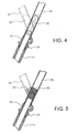
- Fig. 4 is a cross-sectional view of the load absorbing member according to a first embodiment, in which the same reference numerals represent the same or equivalent parts.
- a thick front fork 15 is inserted through the inside of the head pipe 11 and is steerably supported by a bearing member 34.
- the lower end of the handle pipe 20 having flexibility is inserted and fixed to the outside of the upper end of the front fork 15, and one end of an elongated resilient member 32 is inserted and fixed to the inside of the upper end of the front fork 15.
- the other end of the resilient member 32 is inserted into the inside of the handle pipe 20 simultaneously when the handle pipe 20 is inserted on the outer periphery of the upper end of the front fork 15.
- a forward load exceeding the predetermined reference value is applied to the restraining pad 30, the handle pipe 20 which is thinner than the front fork 15 starts to bend.
- a stress exceeds a yield point (stress limit) of the handle pipe 20 the handle pipe starts plastic deformation, and as shown in the same drawing by a broken line, the handle pipe 20 starts to bend forward at a portion near the upper end of the front fork 15.
- Fig. 8 shows a drawing showing a relation between the amount of forward movement of the restraining pad 30 and a load applied to the breast of the occupant. If the resilient member 32 is not inserted on the handle pipe 20, the handle pipe 20 is broken at a moment when the stress exceeds a yield point and hence it cannot maintain its resiliency as shown in the same drawing by a broken line, whereby the load exerted to the restraining pad 30 is released.
- the handle pipe 20 can maintain its resiliency in the plastic range exceeding the yield point. Therefore, the relation between the amount of forward movement of the restraining pad 30 and the load applied to the breast of the occupant can be maintained substantially constantly as shown in Fig. 8 by a solid line, even after the handle pipe 20 exceeds the yield point. Consequently, even when a load exceeding the stress limit of the handle pipe 20 is applied to the restraining pad 30, part of the load can be absorbed, and hence the load applied to the occupant can be reduced.
- Fig. 5 is a cross-sectional view of the load absorbing member according to a second embodiment, and the same reference numerals represent the same or equivalent parts.
- the upper portion of the thick front fork 15 is inserted into the inside of the head pipe 11, and is steerably supported by a bearing member 34.
- the lower end of the handle pipe 20 having flexibility is inserted and fixed to the outside of the upper end of the front fork 15, and a coil spring 33 is inserted into the inside thereof.
- the handle pipe 20 when a forward load exceeding a predetermined reference value is applied to the restraining pad 30, the handle pipe 20, which is thinner than the front fork 15 starts to bend.
- the handle pipe 20 starts plastic deformation, and as shown in the same drawing by a broken line, the handle pipe 20 starts to bend forward at a portion near the upper end of the front fork 15.
- the coil spring 33 since the coil spring 33 is inserted into the bending portion of the handle pipe 20, the handle pipe 20 is not broken even when the stress exceeds its own yield points, and can maintain its resiliency.
- the load absorbing member is provided on the handle pipe 20 for connecting the steering handle 16 and the front fork 15 .
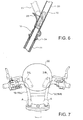
- the present invention is not limited thereto, and as shown in Fig. 7 as an example, the load absorbing members may be provided at root portions A of left and right handle members 16L, 16R surrounded by broken circles respectively as long as it is a two-wheel vehicle having a structure in which the handle 16 includes the pair of the left and right handles 16L, 16R and serves also as the handle pipe 20.
Landscapes
- Engineering & Computer Science (AREA)
- Mechanical Engineering (AREA)
- Steering Devices For Bicycles And Motorcycles (AREA)
- Handcart (AREA)
- Steering Controls (AREA)
Abstract
Description
- The present invention relates to an occupant restraining device for a two-wheel vehicle and, more specifically, to an occupant restraining device for a two-wheel vehicle for restraining the movement of an occupant forwardly of a vehicle body.
- In a motorcycle, as a technique to restrain the movement of an occupant forwardly of a vehicle body, Patent Document JP-A-11-278342 discloses a technique in which an airbag is disposed near a meter panel of a two-wheel vehicle, and the airbag is activated upon detection of an impact.
- In the technique in Patent Document JP-A-11-278342, since a space for mounting an airbag unit or a control unit thereof must be secured in the vicinity of the meter panel, and an acceleration sensor must be mounted, it is difficult to apply it to a two-wheel vehicle of a small size.
- An object of the present invention is to solve the aforementioned problem in the related art, and to provide an occupant restraining device for a two-wheel vehicle which can be applied to a small vehicle easily and can reduce a load applied to the occupant without upsizing a pad.
- In order to achieve the object described above, the present invention is an occupant movement restraining device for restraining the movement of an occupant of a two-wheel vehicle forwardly of a vehicle body comprising a restraining pad mounted to a handle so as to oppose to the occupant, a pipe-shaped steering member steerably supported by a head pipe, a pipe-shaped handle connecting member for connecting the handle with the steering member, and a load absorbing member for absorbing a forward load applied to the restraining pad and allowing the handle connecting member to be deformed so as to incline toward the front at a predetermined position are provided.
- Part of the load applied to the restraining pad is consumed and absorbed as energy for causing the handle connecting member to incline toward the front in the load absorbing member, so that a load applied to the occupant can be reduced.
- The load absorbing member can cause the handle connecting member in the plastic range exceeding a yield point to maintain a predetermined resiliency.
- According to this feature, since the handle connecting member in the plastic range exceeding the yield point can maintain resiliency, the load applied to the restraining pad can be absorbed also after having exceeded the yield point.
- For example, the load absorbing member is inserted at one end into the steering member and at the other end into the handle connecting member, and an end of the steering member and an end of the handle connecting member are fitted to each other.
- Or the load absorbing member can be inserted into the handle connecting member inside the predetermined position thereof and the end of the steering member and the end of the handle connecting member are fitted to each other.
- The load absorbing member can comprise a resilient member that can be, for example, an coil spring.
- According to these features, the resiliency of the handle connecting member at the plastic range exceeding the yield point can be, advantageously, maintained simply by adding the resilient member or the coil spring.
- The occupant restraining device can further comprise a reinforcing member for limiting the amount of forward inclination of the handle connecting member.
- According to this feature, since the amount of forward inclination of the handle connecting member is limited, the position of the restraining pad can be maintained at least at a predetermined height.
-
- Fig. 1 is a side view of a scooter type motorcycle to which an occupant restraining device according to the present invention.
- Fig. 2 is a front view showing an example of a handle to which a restraining pad is mounted.
- Fig. 3 is a drawing showing a state in which the movement of an occupant is prevented by the restraining pad.
- Fig. 4 is a cross-sectional view of a load absorbing member according to a first embodiment.
- Fig. 5 is a cross-sectional view of the load absorbing member according to a second embodiment.
- Fig. 6 is a cross-sectional view showing an example of a reinforcing member for limiting the angle of inclination of a handle pipe.
- Fig. 7 is a front view showing another example of the handle to which the restraining pad is mounted.
- Fig. 8 is a drawing showing a relation between the amount of movement of the restraining pad and a load applied to the occupant.
-
- Referring now to the drawings, a preferred embodiment of the present invention will be described in detail. Fig. 1 is a side view of a scooter type motorcycle to which an occupant restraining device of the present invention is applied, in which a
vehicle body frame 10 mainly includes amain frame pipe 12 provided with ahead pipe 11 secured at the front end thereof, across pipe 13 secured to the rear end of themain frame pipe 12 at a right angle and horizontally, and a pair of left and right rear frame pipes 14 (14L, 14R) connected at the front ends thereof to the both ends of thecross pipe 13. - The
main frame pipe 12 includes adown frame section 12a inclining downward toward the rear from thehead pipe 11 and a lower frame section 12b extending rearward from the rear end of thedown frame section 12a substantially horizontally integrally connected with each other. Thecross pipe 13 extends laterally of thevehicle body frame 10, and the rear end of themain frame pipe 12 is secured to the center of thecross pipe 13 at a right angle. The pair of the left and rightrear frame pipes 14 includerise frame sections 14a extending upward from both ends of thecross pipe 13 toward the rear, and upper frame portions 14b extending substantially horizontally from the rear ends of therise frame sections 14a toward the rear and curved in a horizontal plane so that the rear end openings face each other integrally connected to each other. - A
front fork 15 as a steering member for supporting a front wheel Wf is steerably supported by thehead pipe 11, and asteering handle 16 is connected to the upper end of thefront fork 15 via ahandle pipe 20 as the handle connecting member. A power unit P including an engine E disposed in front of a rear wheel Wr and a stepless transmission M disposed on the left side of the rear wheel Wr are supported at the front portion of therear frame pipe 14 so as to be capable of pivoting in the vertical direction, and the rear wheel Wr is journaled at the rear portion of the power unit P. Anair cleaner 29 is disposed on the upper left side of the rear wheel Wr. - Provided between the rear portion of the power unit P and the left side of the rear frame pipe 14L is a
rear cushion unit 17. Anexhaust pipe 18 for introducing exhaust gas from the engine E extends from the engine E to the right side of the rear wheel Wr, and theexhaust pipe 18 is connected to anexhaust muffler 19 disposed on the right side of the rear wheel Wr. Astorage box 25 is supported between the front portions of the left and rightrear frame pipes 14 so as to be disposed above the engine E. - The
vehicle body frame 10 is covered by avehicle body cover 21 formed of synthetic resin, and thevehicle body cover 21 includes aleg shield 22 for covering the front side of the feet of the occupant, astep floor 23 continuing to the lower portion of theleg shield 22 for placing the feet of the occupant, and side covers 24 continuing from thestep floor 23 for covering the rear portion of the vehicle body from both sides. - The
storage box 25 and the fuel tank (not shown) are covered by theside cover 24, and aseat 26 for covering thestorage box 25 from above is mounted to the upper portion of theside cover 24 so as to be capable of opening and closing. In other words, thestep floor 23 is formed on thevehicle body cover 21 so as to be disposed between thesteering handle 16 and theseat 26, and a frame-side bracket 27 is disposed downwardly of the rear end of thestep floor 23 for pivotably supporting the power unit P to thevehicle body frame 10. - Referring also to Fig. 2, a pair of left and
right plate members steering handle 16, and arestraining pad 30 is mounted to theplate members seat 26. With thisrestraining pad 30, as shown in Fig. 3, since the portion of the occupant near the breast is held by therestraining pad 30 even though the occupant moves forward due to the inertia when the brake is applied and hence further movement is prevented, the forward movement of the occupant is limited within a predetermined range. In this embodiment, a load absorbing member for absorbing a forward load when the forward load exceeding a predetermined reference value is applied to therestraining pad 30 and alleviating a load applied to the occupant is added to thehandle pipe 20. - Fig. 4 is a cross-sectional view of the load absorbing member according to a first embodiment, in which the same reference numerals represent the same or equivalent parts.
- A
thick front fork 15 is inserted through the inside of thehead pipe 11 and is steerably supported by abearing member 34. The lower end of thehandle pipe 20 having flexibility is inserted and fixed to the outside of the upper end of thefront fork 15, and one end of an elongatedresilient member 32 is inserted and fixed to the inside of the upper end of thefront fork 15. The other end of theresilient member 32 is inserted into the inside of thehandle pipe 20 simultaneously when thehandle pipe 20 is inserted on the outer periphery of the upper end of thefront fork 15. - In this structure, a forward load exceeding the predetermined reference value is applied to the
restraining pad 30, thehandle pipe 20 which is thinner than thefront fork 15 starts to bend. When a stress exceeds a yield point (stress limit) of thehandle pipe 20, the handle pipe starts plastic deformation, and as shown in the same drawing by a broken line, thehandle pipe 20 starts to bend forward at a portion near the upper end of thefront fork 15. - Fig. 8 shows a drawing showing a relation between the amount of forward movement of the
restraining pad 30 and a load applied to the breast of the occupant. If theresilient member 32 is not inserted on thehandle pipe 20, thehandle pipe 20 is broken at a moment when the stress exceeds a yield point and hence it cannot maintain its resiliency as shown in the same drawing by a broken line, whereby the load exerted to therestraining pad 30 is released. - In contrast, in this embodiment, since the
front fork 15 and thehandle pipe 20 are connected firmly, and the both of them are connected also resiliently by theresilient member 32, thehandle pipe 20 can maintain its resiliency in the plastic range exceeding the yield point. Therefore, the relation between the amount of forward movement of therestraining pad 30 and the load applied to the breast of the occupant can be maintained substantially constantly as shown in Fig. 8 by a solid line, even after thehandle pipe 20 exceeds the yield point. Consequently, even when a load exceeding the stress limit of thehandle pipe 20 is applied to therestraining pad 30, part of the load can be absorbed, and hence the load applied to the occupant can be reduced. - Fig. 5 is a cross-sectional view of the load absorbing member according to a second embodiment, and the same reference numerals represent the same or equivalent parts.
- The upper portion of the
thick front fork 15 is inserted into the inside of thehead pipe 11, and is steerably supported by abearing member 34. The lower end of thehandle pipe 20 having flexibility is inserted and fixed to the outside of the upper end of thefront fork 15, and acoil spring 33 is inserted into the inside thereof. - In this structure, when a forward load exceeding a predetermined reference value is applied to the
restraining pad 30, thehandle pipe 20, which is thinner than thefront fork 15 starts to bend. When the stress exceeds a yield point (stress limit) of thehandle pipe 20, thehandle pipe 20 starts plastic deformation, and as shown in the same drawing by a broken line, thehandle pipe 20 starts to bend forward at a portion near the upper end of thefront fork 15. However, according to this embodiment, since thecoil spring 33 is inserted into the bending portion of thehandle pipe 20, thehandle pipe 20 is not broken even when the stress exceeds its own yield points, and can maintain its resiliency. - In the aforementioned respective embodiments, since the
handle pipe 20 is bent about the portion near the upper portion of thefront fork 15, the position thereof is lowered as the amount of the movement of therestraining pad 30 increases. Therefore, as shown in Fig. 6, in this embodiment, a reinforcingmember 28 for limiting the angle of inclination of thehandle pipe 20, or the amount of movement of therestraining pad 30 for the lower portion of thehandle pipe 20 below the bent portion or for thehead pipe 11. Accordingly, even when a significant forward load is applied to therestraining pad 30, the position of therestraining pad 30 can be maintained at least at the predetermined height. - In the aforementioned embodiment, a case in which the load absorbing member is provided on the
handle pipe 20 for connecting thesteering handle 16 and thefront fork 15 has been described. However, the present invention is not limited thereto, and as shown in Fig. 7 as an example, the load absorbing members may be provided at root portions A of left andright handle members handle 16 includes the pair of the left andright handles handle pipe 20.
Claims (7)
- Occupant restraining device for a two-wheel vehicle comprising:a restraining pad (30) mounted to a handle (16) so as to oppose to the occupant;a pipe-shaped steering member(20) steerably supported by a head pipe (11);a pipe-shaped handle connecting member (20) for connecting the handle (16) with the steering member (15); anda load absorbing member for absorbing a forward load applied to the restraining pad (30) and allowing the handle connecting member (20) to be deformed so as to incline toward the front at a predetermined position.
- Occupant restraining device for a two-wheel vehicle according to Claim 1, characterized in that the load absorbing member causes the handle connecting member (20) in the plastic range exceeding a yield point to maintain a predetermined resiliency.
- Occupant restraining device for a two-wheel vehicle according to Claim 1 or 2, characterized in that the load absorbing member is inserted at one end into the steering member (15) and at the other end into the handle connecting member (20), and an end of the steering member (15) and an end of the handle connecting member (20) are fitted to each other.
- Occupant restraining device for a two-wheel vehicle according to Claim 1 or 2, characterized in that the load absorbing member is inserted into the handle connecting member (20) inside the predetermined position thereof and the end of the steering member (15) and the end of the handle connecting member (20) are fitted to each other.
- Occupant restraining member according to any one of Claims 1 to 4, in which the load absorbing member comprises a resilient member (32).
- Occupant restraining member according to Claim 4, in which the absorbing member is a coil spring (33).
- Occupant restraining device for a two-wheel vehicle according to any one of Claims 1 to 6, further comprising a reinforcing member (28) for limiting the amount of forward inclination of the handle connecting member (20).
Applications Claiming Priority (2)
| Application Number | Priority Date | Filing Date | Title |
|---|---|---|---|
| JP2004179849A JP4225496B2 (en) | 2004-06-17 | 2004-06-17 | Crew restraint device for motorcycles |
| JP2004179849 | 2004-06-17 |
Publications (3)
| Publication Number | Publication Date |
|---|---|
| EP1607317A2 true EP1607317A2 (en) | 2005-12-21 |
| EP1607317A3 EP1607317A3 (en) | 2008-12-17 |
| EP1607317B1 EP1607317B1 (en) | 2010-05-26 |
Family
ID=34940135
Family Applications (1)
| Application Number | Title | Priority Date | Filing Date |
|---|---|---|---|
| EP05105066A Expired - Lifetime EP1607317B1 (en) | 2004-06-17 | 2005-06-09 | Occupant restraining device for two-wheel vehicle |
Country Status (5)
| Country | Link |
|---|---|
| EP (1) | EP1607317B1 (en) |
| JP (1) | JP4225496B2 (en) |
| CN (1) | CN100439193C (en) |
| ES (1) | ES2346544T3 (en) |
| TW (1) | TWI285166B (en) |
Cited By (1)
| Publication number | Priority date | Publication date | Assignee | Title |
|---|---|---|---|---|
| WO2021156216A1 (en) * | 2020-02-07 | 2021-08-12 | Autoliv Development Ab | Vehicle having at least one handlebar, especially motorcycle, with a safety device |
Families Citing this family (3)
| Publication number | Priority date | Publication date | Assignee | Title |
|---|---|---|---|---|
| JP4787051B2 (en) * | 2006-03-31 | 2011-10-05 | 本田技研工業株式会社 | Shock absorption structure for motorcycles |
| JP4766556B2 (en) * | 2006-03-31 | 2011-09-07 | 本田技研工業株式会社 | Crew restraint device for motorcycles |
| WO2025074479A1 (en) * | 2023-10-02 | 2025-04-10 | 本田技研工業株式会社 | Saddled vehicle |
Citations (1)
| Publication number | Priority date | Publication date | Assignee | Title |
|---|---|---|---|---|
| JPH11278342A (en) | 1998-03-30 | 1999-10-12 | Honda Motor Co Ltd | Airbag device for motorcycles |
Family Cites Families (8)
| Publication number | Priority date | Publication date | Assignee | Title |
|---|---|---|---|---|
| GB2003096A (en) * | 1977-08-24 | 1979-03-07 | Transport Sec Of State For | Motor cycle safety devices |
| DE3308772A1 (en) * | 1983-03-11 | 1984-09-20 | Hans-Günther 8000 München Stadelmayr | Safety vehicle, in particular safety bicycle, motorcycle, safety scooter, including tilting scooter |
| DE4026172A1 (en) * | 1990-08-16 | 1992-07-09 | Taeubert Annette | Child's head protective cushion of bicycle handlebars - is fitted to handlebar centre by steel sheet brackets, steel wire, etc. |
| US5219104A (en) * | 1991-12-13 | 1993-06-15 | Huffy Corporation | Sports article handlebar pad |
| SK349492A3 (en) * | 1992-11-26 | 1995-01-12 | Rudolf Novotny | Device for fastening of elastic adapter of handle-bars into the fork of bicycle |
| DE19737599A1 (en) * | 1997-08-28 | 1999-03-04 | Bayerische Motoren Werke Ag | Resilient, steerable axle suspension for a two-wheeler |
| DE29806407U1 (en) * | 1998-04-08 | 1998-08-06 | Hermann, Stefan, 89614 Öpfingen | Seat belt device for two-wheelers |
| AU6393099A (en) * | 1998-10-13 | 2000-05-01 | Demarini Sports, Inc. | Handlebar system |
-
2004
- 2004-06-17 JP JP2004179849A patent/JP4225496B2/en not_active Expired - Fee Related
-
2005
- 2005-04-08 TW TW094111248A patent/TWI285166B/en not_active IP Right Cessation
- 2005-06-09 EP EP05105066A patent/EP1607317B1/en not_active Expired - Lifetime
- 2005-06-09 ES ES05105066T patent/ES2346544T3/en not_active Expired - Lifetime
- 2005-06-10 CN CNB2005100763742A patent/CN100439193C/en not_active Expired - Fee Related
Patent Citations (1)
| Publication number | Priority date | Publication date | Assignee | Title |
|---|---|---|---|---|
| JPH11278342A (en) | 1998-03-30 | 1999-10-12 | Honda Motor Co Ltd | Airbag device for motorcycles |
Cited By (2)
| Publication number | Priority date | Publication date | Assignee | Title |
|---|---|---|---|---|
| WO2021156216A1 (en) * | 2020-02-07 | 2021-08-12 | Autoliv Development Ab | Vehicle having at least one handlebar, especially motorcycle, with a safety device |
| US11679835B2 (en) | 2020-02-07 | 2023-06-20 | Autoliv Development Ab | Vehicle having at least one handlebar, especially motorcycle, with a safety device |
Also Published As
| Publication number | Publication date |
|---|---|
| CN1709762A (en) | 2005-12-21 |
| TWI285166B (en) | 2007-08-11 |
| ES2346544T3 (en) | 2010-10-18 |
| EP1607317B1 (en) | 2010-05-26 |
| CN100439193C (en) | 2008-12-03 |
| JP4225496B2 (en) | 2009-02-18 |
| EP1607317A3 (en) | 2008-12-17 |
| TW200600394A (en) | 2006-01-01 |
| JP2006001411A (en) | 2006-01-05 |
Similar Documents
| Publication | Publication Date | Title |
|---|---|---|
| JP5086831B2 (en) | Motorcycle | |
| JPWO2017154437A1 (en) | Motorcycle | |
| EP1634803B1 (en) | Rider restraining device for two wheel vehicle | |
| CN101939213B (en) | Scooter type vehicle | |
| EP1607317B1 (en) | Occupant restraining device for two-wheel vehicle | |
| JP2001219885A (en) | Airbag device for saddle type vehicle | |
| JP4721280B2 (en) | Vehicle with impact mitigation device | |
| JP4353421B2 (en) | Crew restraint device for motorcycles | |
| JP4169206B2 (en) | Crew restraint device for motorcycles | |
| CN100387482C (en) | Occupant restraint device for two-wheeled vehicles | |
| JP4339549B2 (en) | Airbag device | |
| TW201945236A (en) | Airbag device for saddle-type vehicles | |
| JP4236110B2 (en) | Crew restraint device for motorcycles | |
| JP5005591B2 (en) | Grab rail structure in motorcycles | |
| ES2368912T3 (en) | LOAD TRANSPORT FRAME STRUCTURE FOR A VEHICLE. | |
| JP2008080883A (en) | Front bumper | |
| CN204398851U (en) | The configuration structure of two-wheeled liquid reserve tank | |
| JP2003127944A (en) | Airbag device for motorcycles | |
| JP4908126B2 (en) | Front fender | |
| JP2009101888A (en) | Scooter type motorcycle | |
| JP2000313263A (en) | Built-in type child seat |
Legal Events
| Date | Code | Title | Description |
|---|---|---|---|
| PUAI | Public reference made under article 153(3) epc to a published international application that has entered the european phase |
Free format text: ORIGINAL CODE: 0009012 |
|
| 17P | Request for examination filed |
Effective date: 20050609 |
|
| AK | Designated contracting states |
Kind code of ref document: A2 Designated state(s): AT BE BG CH CY CZ DE DK EE ES FI FR GB GR HU IE IS IT LI LT LU MC NL PL PT RO SE SI SK TR |
|
| AX | Request for extension of the european patent |
Extension state: AL BA HR LV MK YU |
|
| PUAL | Search report despatched |
Free format text: ORIGINAL CODE: 0009013 |
|
| AK | Designated contracting states |
Kind code of ref document: A3 Designated state(s): AT BE BG CH CY CZ DE DK EE ES FI FR GB GR HU IE IS IT LI LT LU MC NL PL PT RO SE SI SK TR |
|
| AX | Request for extension of the european patent |
Extension state: AL BA HR LV MK YU |
|
| RIC1 | Information provided on ipc code assigned before grant |
Ipc: B62J 27/00 20060101AFI20050922BHEP Ipc: B62K 21/12 20060101ALI20081110BHEP Ipc: B62K 11/14 20060101ALI20081110BHEP |
|
| AKX | Designation fees paid |
Designated state(s): ES FR IT |
|
| REG | Reference to a national code |
Ref country code: DE Ref legal event code: 8566 |
|
| GRAP | Despatch of communication of intention to grant a patent |
Free format text: ORIGINAL CODE: EPIDOSNIGR1 |
|
| GRAS | Grant fee paid |
Free format text: ORIGINAL CODE: EPIDOSNIGR3 |
|
| GRAA | (expected) grant |
Free format text: ORIGINAL CODE: 0009210 |
|
| AK | Designated contracting states |
Kind code of ref document: B1 Designated state(s): ES FR IT |
|
| REG | Reference to a national code |
Ref country code: ES Ref legal event code: FG2A Ref document number: 2346544 Country of ref document: ES Kind code of ref document: T3 |
|
| PLBE | No opposition filed within time limit |
Free format text: ORIGINAL CODE: 0009261 |
|
| STAA | Information on the status of an ep patent application or granted ep patent |
Free format text: STATUS: NO OPPOSITION FILED WITHIN TIME LIMIT |
|
| 26N | No opposition filed |
Effective date: 20110301 |
|
| PGFP | Annual fee paid to national office [announced via postgrant information from national office to epo] |
Ref country code: ES Payment date: 20120726 Year of fee payment: 8 |
|
| PGFP | Annual fee paid to national office [announced via postgrant information from national office to epo] |
Ref country code: IT Payment date: 20130619 Year of fee payment: 9 Ref country code: FR Payment date: 20130624 Year of fee payment: 9 |
|
| REG | Reference to a national code |
Ref country code: FR Ref legal event code: ST Effective date: 20150227 |
|
| PG25 | Lapsed in a contracting state [announced via postgrant information from national office to epo] |
Ref country code: IT Free format text: LAPSE BECAUSE OF NON-PAYMENT OF DUE FEES Effective date: 20140609 |
|
| PG25 | Lapsed in a contracting state [announced via postgrant information from national office to epo] |
Ref country code: FR Free format text: LAPSE BECAUSE OF NON-PAYMENT OF DUE FEES Effective date: 20140630 |
|
| REG | Reference to a national code |
Ref country code: ES Ref legal event code: FD2A Effective date: 20150724 |
|
| PG25 | Lapsed in a contracting state [announced via postgrant information from national office to epo] |
Ref country code: ES Free format text: LAPSE BECAUSE OF NON-PAYMENT OF DUE FEES Effective date: 20140610 |