EP1606544B1 - End fitting for a flexible pipe, pipe assembly and method of assembling the pipe assembly - Google Patents
End fitting for a flexible pipe, pipe assembly and method of assembling the pipe assembly Download PDFInfo
- Publication number
- EP1606544B1 EP1606544B1 EP04722914A EP04722914A EP1606544B1 EP 1606544 B1 EP1606544 B1 EP 1606544B1 EP 04722914 A EP04722914 A EP 04722914A EP 04722914 A EP04722914 A EP 04722914A EP 1606544 B1 EP1606544 B1 EP 1606544B1
- Authority
- EP
- European Patent Office
- Prior art keywords
- bore
- pipe
- end fitting
- portions
- layers
- Prior art date
- Legal status (The legal status is an assumption and is not a legal conclusion. Google has not performed a legal analysis and makes no representation as to the accuracy of the status listed.)
- Expired - Lifetime
Links
- 238000000034 method Methods 0.000 title claims abstract description 5
- 241000237503 Pectinidae Species 0.000 claims 1
- 235000020637 scallop Nutrition 0.000 claims 1
- 238000007789 sealing Methods 0.000 description 6
- 239000012530 fluid Substances 0.000 description 5
- 239000000463 material Substances 0.000 description 3
- 239000004593 Epoxy Substances 0.000 description 2
- 239000002033 PVDF binder Substances 0.000 description 2
- 230000004888 barrier function Effects 0.000 description 2
- 238000010276 construction Methods 0.000 description 2
- 229920001903 high density polyethylene Polymers 0.000 description 2
- 239000004700 high-density polyethylene Substances 0.000 description 2
- 238000012986 modification Methods 0.000 description 2
- 230000004048 modification Effects 0.000 description 2
- 238000000465 moulding Methods 0.000 description 2
- 229920002981 polyvinylidene fluoride Polymers 0.000 description 2
- 238000004804 winding Methods 0.000 description 2
- 229910000975 Carbon steel Inorganic materials 0.000 description 1
- 239000004677 Nylon Substances 0.000 description 1
- 239000010962 carbon steel Substances 0.000 description 1
- 239000002131 composite material Substances 0.000 description 1
- 238000005260 corrosion Methods 0.000 description 1
- 230000007797 corrosion Effects 0.000 description 1
- 239000010779 crude oil Substances 0.000 description 1
- 239000000203 mixture Substances 0.000 description 1
- 229920001778 nylon Polymers 0.000 description 1
- 230000035515 penetration Effects 0.000 description 1
- 239000004033 plastic Substances 0.000 description 1
- 229920003023 plastic Polymers 0.000 description 1
- 229920000642 polymer Polymers 0.000 description 1
- 230000001737 promoting effect Effects 0.000 description 1
- 229910001256 stainless steel alloy Inorganic materials 0.000 description 1
Images

Classifications
-
- F—MECHANICAL ENGINEERING; LIGHTING; HEATING; WEAPONS; BLASTING
- F16—ENGINEERING ELEMENTS AND UNITS; GENERAL MEASURES FOR PRODUCING AND MAINTAINING EFFECTIVE FUNCTIONING OF MACHINES OR INSTALLATIONS; THERMAL INSULATION IN GENERAL
- F16L—PIPES; JOINTS OR FITTINGS FOR PIPES; SUPPORTS FOR PIPES, CABLES OR PROTECTIVE TUBING; MEANS FOR THERMAL INSULATION IN GENERAL
- F16L13/00—Non-disconnectable pipe joints, e.g. soldered, adhesive, or caulked joints
- F16L13/14—Non-disconnectable pipe joints, e.g. soldered, adhesive, or caulked joints made by plastically deforming the material of the pipe, e.g. by flanging, rolling
- F16L13/147—Non-disconnectable pipe joints, e.g. soldered, adhesive, or caulked joints made by plastically deforming the material of the pipe, e.g. by flanging, rolling by radially expanding the inner part
-
- F—MECHANICAL ENGINEERING; LIGHTING; HEATING; WEAPONS; BLASTING
- F16—ENGINEERING ELEMENTS AND UNITS; GENERAL MEASURES FOR PRODUCING AND MAINTAINING EFFECTIVE FUNCTIONING OF MACHINES OR INSTALLATIONS; THERMAL INSULATION IN GENERAL
- F16L—PIPES; JOINTS OR FITTINGS FOR PIPES; SUPPORTS FOR PIPES, CABLES OR PROTECTIVE TUBING; MEANS FOR THERMAL INSULATION IN GENERAL
- F16L25/00—Construction or details of pipe joints not provided for in, or of interest apart from, groups F16L13/00 - F16L23/00
- F16L25/06—Construction or details of pipe joints not provided for in, or of interest apart from, groups F16L13/00 - F16L23/00 comprising radial locking means
- F16L25/08—Construction or details of pipe joints not provided for in, or of interest apart from, groups F16L13/00 - F16L23/00 comprising radial locking means in the form of screws, nails or the like
-
- F—MECHANICAL ENGINEERING; LIGHTING; HEATING; WEAPONS; BLASTING
- F16—ENGINEERING ELEMENTS AND UNITS; GENERAL MEASURES FOR PRODUCING AND MAINTAINING EFFECTIVE FUNCTIONING OF MACHINES OR INSTALLATIONS; THERMAL INSULATION IN GENERAL
- F16L—PIPES; JOINTS OR FITTINGS FOR PIPES; SUPPORTS FOR PIPES, CABLES OR PROTECTIVE TUBING; MEANS FOR THERMAL INSULATION IN GENERAL
- F16L33/00—Arrangements for connecting hoses to rigid members; Rigid hose-connectors, i.e. single members engaging both hoses
- F16L33/01—Arrangements for connecting hoses to rigid members; Rigid hose-connectors, i.e. single members engaging both hoses specially adapted for hoses having a multi-layer wall
-
- F—MECHANICAL ENGINEERING; LIGHTING; HEATING; WEAPONS; BLASTING
- F16—ENGINEERING ELEMENTS AND UNITS; GENERAL MEASURES FOR PRODUCING AND MAINTAINING EFFECTIVE FUNCTIONING OF MACHINES OR INSTALLATIONS; THERMAL INSULATION IN GENERAL
- F16L—PIPES; JOINTS OR FITTINGS FOR PIPES; SUPPORTS FOR PIPES, CABLES OR PROTECTIVE TUBING; MEANS FOR THERMAL INSULATION IN GENERAL
- F16L33/00—Arrangements for connecting hoses to rigid members; Rigid hose-connectors, i.e. single members engaging both hoses
- F16L33/20—Undivided rings, sleeves, or like members contracted on the hose or expanded inside the hose by means of tools; Arrangements using such members
- F16L33/213—Undivided rings, sleeves, or like members contracted on the hose or expanded inside the hose by means of tools; Arrangements using such members only a sleeve being expanded inside the hose
Definitions
- the present invention relates to a flexible pipe and end fitting assembly and, more particularly, to such an assembly which is relatively simple in constriction, low in cost, and easy to assemble.
- the present invention is directed to a flexible pipe/end fitting assembly that meets all of these criteria, including an effective seal between the pipe and its end fitting, yet is relatively simple in construction, easy to assemble, and inexpensive.
- US 6,405,762 discloses a composite pipe assembly.
- FR 1325153 discloses an end fitting for a flexible hose.
- an end fitting for a flexible pipe having multiple layers for use in subsea environments
- the end fitting comprising a housing defining a bore for receiving an end portion of the pipe, a surface of the housing defining the bore having at least two axially spaced raised portions; wherein the bore is stepped to define at least two bore portions having different diameters, such that end portions of all of the layers of the pipe may extend in the bore portion with a greater diameter; and end portions of less than all the layers extend in the bore portion with a lesser diameter, the raised portions are formed in the bore portion having the lesser diameter for engagement with a corresponding outer surface of the pipe in said bore portion having the lesser diameter to provide a seal, and the raised portions each have a curved cross-section.
- a pipe assembly comprising:
- an end fitting according to an embodiment of the invention is shown, in general, by the reference numeral 10.
- the end fitting 10 is in the form of a generally tubular-shaped housing that includes an armular flange 10a extending radially outwardly therefrom to permit the end fitting to be connected to other equipment.
- a radially extending test port 10b extends through the wall of the end fitting 10, and the end fitting has a reduced outer diameter portion 10c through which two radially extending, externally threaded, bores 10d and 10e extend that are adapted to receive externally threaded bolts (not shown in Fig. 1 ) for reasons to be described.
- the end fitting 10 has a continuous bore extending therethrough which is stepped to form an end portion 12a, a scalloped or undulating intermediate portion 12b, and an opposite end portion 12c.
- the inner diameter of the intermediate bore portion 12b is greater than the inner diameter of the end bore portion 12a and less than the inner diameter of the end bore portion 12c.
- the projections 14a and 14b can be formed in any conventional manner such as by scalloping or undulating the latter wall, molding the projections integrally with the wall, etc.
- Fig. 2 depicts a flexible pipe 20 connected to the end fitting 10.
- the pipe 20 is formed by an inner tubular layer 22, preferably in the form of an interlocking metallic carcass fabricated from a range of corrosion resistant stainless steel alloys depending on the fluid to be conveyed.
- a tubular barrier layer 24 extends around the layer 22 with the inner surface of the former being in intimate contact with the outer surface of the latter.
- the material forming the layer 24 can vary, an example would be a plastic material, such as a polymer, so as to be chemically resistant to the fluid being conveyed. Examples of the latter material are high-density polyethylene (HDPE), PA11 nylon, and polyvinylidene fluoride (PVDF).
- HDPE high-density polyethylene
- PA11 nylon PA11 nylon
- PVDF polyvinylidene fluoride
- An armor, or strength, layer 26 is wrapped around the layer 24 with the inner surface of the former being in intimate contact with the outer surface of the latter.
- the layer 26 is designed to provide resistance to internal and external pressure in the hoop direction, and can take several forms.
- the layer 26 can be formed by circumferentially winding one or more profiled wires, preferably formed of carbon steel, around the layer 24, with adjacent windings being interlocked, to form an armor layer.
- the length of the layer 26 is less than that of the layers 22 and 24 and the layer 26 is positioned so that its end abuts the shoulder between the intermediate bore portion 12b and the end bore portion 12c, and so that its corresponding end portion engages the end bore portion 22c.
- Two bolts 28a and 28b are threaded into the bores 10d and 10e with their respective ends engaging the layer 26 to secure the pipe 20 to the end fitting 10.
- a retaining ring 30 is disposed in the end portion of the pipe 10, and more particularly, along that portion of the inner layer 22 extending along the intermediate bore portion 12b.
- the ring 30 has an annular flange 30a extending radially outwardly from one end thereof that engages the above shoulder at the junction between the end bore portion 12a and the intermediate bore portion 12b.
- the respective end portions of the pipe layers 22 and 24 extend between the inner surface of the ring 30 and the wall of the end fitting 10 defining the intermediate bore portion 12b, with the respective ends of the layers abutting the flange 30a.
- the projections 14a and 14b sealingly engage the corresponding outer surfaces of the pipe layer 24 with the ring 30 promoting the engagement.
- the pipe 20 is inserted into the end fitting 10 with the layers 22, 24, and 26 and the ring 30 in the positions shown in Fig. 2 and discussed above.
- the bolts 28a and 28b are then screwed into the bores 10d and 10e until they engage the layer 26.
- a dolly 40 ( Fig. 2 ) is placed in the bore 10 in a spaced relation to the ring 30 and the corresponding end of the pipe 10.
- the dolly 40 has a tapered cross section and a maximum outer diameter slightly larger than the inner diameter of the pipe ring 30.
- a rod 40a is connected to the dolly and is driven by a prime mover (not shown) that pulls the rod and the dolly in a direction from left-to-right as viewed in Fig. 2 .
- the dolly 40 thus engages the ring 30 and forces it radially outwardly with sufficient force to increase the inner diameter of the ring 30 to a value that is substantially equal to that of the outer diameter of the dolly 40.
- the flexible pipe/end fitting assembly of the above embodiment meets all of the criteria required for a flexible pipe as described above, yet is relatively simple in construction, is relatively easy to assemble, is relatively inexpensive, and is relatively easy to test.
Landscapes
- Engineering & Computer Science (AREA)
- General Engineering & Computer Science (AREA)
- Mechanical Engineering (AREA)
- Rigid Pipes And Flexible Pipes (AREA)
- Gasket Seals (AREA)
- Joints With Sleeves (AREA)
- Shaping Of Tube Ends By Bending Or Straightening (AREA)
Abstract
Description
- The present invention relates to a flexible pipe and end fitting assembly and, more particularly, to such an assembly which is relatively simple in constriction, low in cost, and easy to assemble.
- When crude oil, gas, or other similar fluids are transported through pipes and/or risers in subsea environments, several challenges are presented with respect to designing the pipes and risers for transporting the fluids, and providing proper end fittings for same. For example, the pipes and risers must provide a fluid barrier while being resistant to collapse and penetration, yet must be flexible and connectable to other equipment. Also, an effective seal must be established between the end bore portion of the pipe and the end fitting. To this end, many designs of this type require sophisticated seal rings between the pipe and its end fitting, which designs are expensive and require extensive assembly labor.
- The present invention is directed to a flexible pipe/end fitting assembly that meets all of these criteria, including an effective seal between the pipe and its end fitting, yet is relatively simple in construction, easy to assemble, and inexpensive.
-
US 6,405,762 discloses a composite pipe assembly.FR 1325153 - According to a first aspect of the present invention there is provided an end fitting for a flexible pipe having multiple layers, for use in subsea environments
the end fitting comprising a housing defining a bore for receiving an end portion of the pipe, a surface of the housing defining the bore having at least two axially spaced raised portions;
wherein
the bore is stepped to define at least two bore portions having different diameters, such that end portions of all of the layers of the pipe may extend in the bore portion with a greater diameter; and end portions of less than all the layers extend in the bore portion with a lesser diameter,
the raised portions are formed in the bore portion having the lesser diameter for engagement with a corresponding outer surface of the pipe in said bore portion having the lesser diameter to provide a seal, and
the raised portions each have a curved cross-section. - According to a second aspect of the present invention there is provided a method of assembling a pipe assembly, comprising:
- providing a housing defining a bore, a surface of the housing defining the bore having at least two axially spaced raised portions each having a curved cross-section, wherein the bore is stepped to define at least two bore portions having different diameters, and wherein the raised portions are formed in the bore portion having a lesser diameter, and
- inserting an end portion of a flexible pipe having multiple layers in the bore such that end portions of all of the layers of the pipe extend in the bore portion with a greater diameter and end portions of less than all the layers extend in the bore portion with the lesser diameter, and the raised portions engage a corresponding outer surface of the pipe in said bore portion having the lesser diameter to provide a seal.
-
-
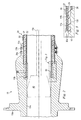
Fig. 1 is a partial longitudinal sectional view of an end fitting assembly according to an embodiment of the present invention. -
Fig. 2 is a view similar to that ofFig. 1 , but depicting the end fitting ofFig. 1 connected to a flexible pipe. -
Fig. 3 is an enlarged, partial view of a detail ofFig. 2 . - Referring to
Fig. 1 of the drawing, an end fitting according to an embodiment of the invention is shown, in general, by thereference numeral 10. Theend fitting 10 is in the form of a generally tubular-shaped housing that includes anarmular flange 10a extending radially outwardly therefrom to permit the end fitting to be connected to other equipment. - A radially extending
test port 10b extends through the wall of the end fitting 10, and the end fitting has a reducedouter diameter portion 10c through which two radially extending, externally threaded,bores Fig. 1 ) for reasons to be described. - The
end fitting 10 has a continuous bore extending therethrough which is stepped to form anend portion 12a, a scalloped or undulatingintermediate portion 12b, and anopposite end portion 12c. The inner diameter of theintermediate bore portion 12b is greater than the inner diameter of theend bore portion 12a and less than the inner diameter of theend bore portion 12c. - Two axially spaced, annular, raised,
projections intermediate bore portion 12b. Theprojections -
Fig. 2 depicts aflexible pipe 20 connected to the end fitting 10. Thepipe 20 is formed by an innertubular layer 22, preferably in the form of an interlocking metallic carcass fabricated from a range of corrosion resistant stainless steel alloys depending on the fluid to be conveyed. Atubular barrier layer 24 extends around thelayer 22 with the inner surface of the former being in intimate contact with the outer surface of the latter. Although the material forming thelayer 24 can vary, an example would be a plastic material, such as a polymer, so as to be chemically resistant to the fluid being conveyed. Examples of the latter material are high-density polyethylene (HDPE), PA11 nylon, and polyvinylidene fluoride (PVDF). - An armor, or strength,
layer 26 is wrapped around thelayer 24 with the inner surface of the former being in intimate contact with the outer surface of the latter. Thelayer 26 is designed to provide resistance to internal and external pressure in the hoop direction, and can take several forms. For example, thelayer 26 can be formed by circumferentially winding one or more profiled wires, preferably formed of carbon steel, around thelayer 24, with adjacent windings being interlocked, to form an armor layer. - The length of the
layer 26 is less than that of thelayers layer 26 is positioned so that its end abuts the shoulder between theintermediate bore portion 12b and the end boreportion 12c, and so that its corresponding end portion engages the end bore portion 22c. Twobolts bores layer 26 to secure thepipe 20 to the end fitting 10. - As better shown in
Fig. 3 , aretaining ring 30 is disposed in the end portion of thepipe 10, and more particularly, along that portion of theinner layer 22 extending along theintermediate bore portion 12b. Thering 30 has anannular flange 30a extending radially outwardly from one end thereof that engages the above shoulder at the junction between theend bore portion 12a and theintermediate bore portion 12b. Thus, the respective end portions of thepipe layers ring 30 and the wall of the end fitting 10 defining theintermediate bore portion 12b, with the respective ends of the layers abutting theflange 30a. As a result, theprojections pipe layer 24 with thering 30 promoting the engagement. - As an example of the method of assembling the end fitting 10 to the
pipe 20, thepipe 20 is inserted into the end fitting 10 with thelayers ring 30 in the positions shown inFig. 2 and discussed above. Thebolts bores layer 26. - A dolly 40 (
Fig. 2 ) is placed in thebore 10 in a spaced relation to thering 30 and the corresponding end of thepipe 10. Thedolly 40 has a tapered cross section and a maximum outer diameter slightly larger than the inner diameter of thepipe ring 30. Arod 40a is connected to the dolly and is driven by a prime mover (not shown) that pulls the rod and the dolly in a direction from left-to-right as viewed inFig. 2 . Thedolly 40 thus engages thering 30 and forces it radially outwardly with sufficient force to increase the inner diameter of thering 30 to a value that is substantially equal to that of the outer diameter of thedolly 40. Thus, a significant compressive force is established against thepipe layers pipe 20 in the end fitting 10 and to force theprojections layer 24. Thepipe 20 is then permanently secured to the end fitting 10 in any conventional manner such as by bolting a jacket, or the like (not shown) over the end fitting and/or injecting epoxy over thelayers - With the
projections pipe 20 and the end fitting 10, the flexible pipe/end fitting assembly of the above embodiment meets all of the criteria required for a flexible pipe as described above, yet is relatively simple in construction, is relatively easy to assemble, is relatively inexpensive, and is relatively easy to test. -
- (1) The number of
sealing projections - (2) The
sealing projections intermediate wall portion 12b of the end fitting 12. - (3) The
sealing projections - (4) The composition of each of the
layers - (5) One or more of the
layers - (6) Two or more of the
layers layers - (7) The relative dimensions of the
projections layers - (8) An outer jacket can be placed over the end fitting 10 and the aforementioned additional layers can be extended into a space between the outer jacket and the end fitting and an epoxy can be injected into the space and around the extended portions of the additional layers.
- (9) The scalloped or undulating surfaces defining the
intermediate bore portion 12b can be replaced with a straight surface having sealing members or profiles formed thereon or therein. - (10) The spatial references, such as "under", "over", "between", "outer", "inner" and "surrounding" are for the purpose of illustration only and do not limit the specific orientation or location of the layers described above.
- (11) Conventional ring seals can be provided in addition to the
sealing projections - Although only a few exemplary embodiments of this invention have been described in detail above, those skilled in the art will readily appreciate that many other modifications are possible in the exemplary embodiments without materially departing from the novel teachings and advantages of this invention. Accordingly, all such modifications are intended to be included within the scope of this invention as defined in the appended claims.
Claims (13)
- An end fitting (10) for a flexible pipe (20) having multiple layers, for use in subsea environments,
the end fitting (10) comprising a housing defining a bore for receiving an end portion of the pipe (20), a surface of the housing defining the bore having at least two axially spaced raised portions (14a, 14b);
wherein
the bore is stepped to define at least two bore portions having different diameters (12b and 12c), such that end portions of all of the layers of the pipe (20) may extend in the bore portion with a greater diameter (12c); and end portions of less than all the layers extend in the bore portion with a lesser diameter (12b),
the raised portions (14a, 14b) are formed in the bore portion having the lesser diameter (12b) for engagement with a corresponding outer surface of the pipe in said bore portion having the lesser diameter to provide a seal, and
the raised portions (14a, 14b) each have a curved cross-section. - The end fitting of claim 1 wherein each raised portion (14a, 14b) is formed integrally with the housing.
- The end fitting of claims 1 or 2 wherein each raised portion (14a, 14b) is in the form of an angular ring.
- The end fitting of claim 1 wherein each raised portion (14a, 14b) is formed by providing scallops in the housing surface.
- The end fitting of claim 1 wherein each raised portion (14a, 14b) is formed by providing undulations in the housing surface.
- The end fitting of claim 1 further comprising a radially extending, internally threaded, opening (10d, 10e) formed through the housing and extending to the bore,
and a bolt (28a, 28b) threadedly engaging the opening and adapted to engage the pipe (20). - The end fitting , of claim 1 further comprising a support ring (30) extending within an end portion of the pipe (20) so that the latter end portion of the pipe extends within the raised portion (14a, 14b) and the support ring (30).
- The end fitting of claim 7 wherein the ring (30) has an annular flange (30a) formed thereon that engages a further shoulder defined between the bore portion with the lesser diameter (12b) and a further bore portion (12a) of even lesser diameter.
- The end fitting of claim 8 wherein the flange (30a) extends radially outwardly from the ring (30).
- The end fitting of claims 8 or 9 wherein the flange (30a) extends between the shoulder and the corresponding end of the pipe.
- The end fitting of claim 1 further comprising a radially extending test port (10b) formed through the housing and opening at an outer surface of the housing and at an inner surface of the housing at a location between the raised portions (14a, 14b).
- A pipe assembly comprising an end fitting (10) of any of claims 1 to 11, and a flexible pipe (20) having multiple layers, an end portion thereof extending in the bore, end portions of all of the layers of the pipe extending in the bore portion with the greater diameter and end portions of less than all the layers extending in the bore portion with the lesser diameter, wherein the raised portions engage the corresponding outer surface of the pipe in said bore portion having the lesser diameter to provide a seal.
- A method of assembling a pipe assembly, comprising:providing a housing defining a bore, a surface of the housing defining the bore having at least two axially spaced raised portions (14a, 14b) each having a curved cross-section, wherein the bore is stepped to define at least two bore portions having different diameters (12b, 12c), and wherein the raised portions are formed in the bore portion having a lesser diameter, andinserting an end portion of a flexible pipe (20) having multiple layers (22, 24, 26) in the bore such that end portions of all of the layers of the pipe extend in the bore portion with a greater diameter and end portions of less than all the layers extend in the bore portion with the lesser diameter, and the raised portions engage a corresponding outer surface of the pipe in said bore portion having the lesser diameter to provide a seal.
Applications Claiming Priority (3)
| Application Number | Priority Date | Filing Date | Title |
|---|---|---|---|
| US45765303P | 2003-03-26 | 2003-03-26 | |
| US457653P | 2003-03-26 | ||
| PCT/IB2004/000879 WO2004085905A1 (en) | 2003-03-26 | 2004-03-24 | End fitting for a flexible pipe, pipe assembly and method of assembling the pipe assembly |
Publications (2)
| Publication Number | Publication Date |
|---|---|
| EP1606544A1 EP1606544A1 (en) | 2005-12-21 |
| EP1606544B1 true EP1606544B1 (en) | 2010-10-20 |
Family
ID=33098240
Family Applications (1)
| Application Number | Title | Priority Date | Filing Date |
|---|---|---|---|
| EP04722914A Expired - Lifetime EP1606544B1 (en) | 2003-03-26 | 2004-03-24 | End fitting for a flexible pipe, pipe assembly and method of assembling the pipe assembly |
Country Status (5)
| Country | Link |
|---|---|
| US (1) | US7204524B2 (en) |
| EP (1) | EP1606544B1 (en) |
| BR (1) | BRPI0408940B1 (en) |
| DK (1) | DK1606544T3 (en) |
| WO (1) | WO2004085905A1 (en) |
Families Citing this family (22)
| Publication number | Priority date | Publication date | Assignee | Title |
|---|---|---|---|---|
| US7946629B2 (en) * | 2005-10-07 | 2011-05-24 | Flexpipe Systems Inc. | Pipe coupling and method for installation |
| GB0621543D0 (en) * | 2006-10-30 | 2006-12-06 | Wellstream Int Ltd | Testing and venting pipe annulus |
| BRPI0810610B1 (en) * | 2007-04-27 | 2018-12-04 | Alcoa Inc | riser section for offshore metal drilling and riser section for offshore drilling for oil or other fossil fuels |
| CA2716795C (en) | 2008-02-25 | 2018-07-31 | Nkt Flexibles I/S | A pipe system, a fluid sensing system for a pipe system, and a method of determining a fluid component in an annulus cavity of a pipe |
| US7806187B2 (en) * | 2008-05-19 | 2010-10-05 | Trendsetter Engineering, Inc. | Connector assembly for connecting a hot stab to a hydraulic hose |
| BRPI0913413A2 (en) | 2008-06-03 | 2015-11-24 | Nkt Flexibles Is | pipe system, and gas sensor system for sensing a gas in a cavity of a pipe. |
| US20100154915A1 (en) * | 2008-12-24 | 2010-06-24 | Chao-Chung Wu | Hose |
| US20100237611A1 (en) * | 2009-03-17 | 2010-09-23 | Ya-Ling Hung | Hose and Connector Assembly Having Greater Strength |
| US8485562B2 (en) * | 2011-04-18 | 2013-07-16 | Red Head Brass, Llc | Suction line coupling for emergency vehicles |
| USD699273S1 (en) * | 2013-01-22 | 2014-02-11 | Greif International Holding Bv | Agitator fitting assembly with bushing |
| USD709113S1 (en) * | 2013-01-22 | 2014-07-15 | Greif International Holding Bv | Agitator fitting assembly |
| GB201507718D0 (en) | 2015-05-06 | 2015-06-17 | Ge Oil And Gas Uk Ltd | Termination of a flexible pipe |
| GB201507720D0 (en) | 2015-05-06 | 2015-06-17 | Ge Oil And Gas Uk Ltd | Access provision |
| US10036497B2 (en) * | 2015-10-28 | 2018-07-31 | Sigma Corporation | Joint restraint devices and methods of using same |
| US10132434B2 (en) | 2015-11-23 | 2018-11-20 | Parker-Hannifin Corporation | Hose coupling assembly for subsea applications |
| GB2568898A (en) * | 2017-11-29 | 2019-06-05 | Equinor Energy As | Integrity monitoring of sectioned hoses |
| US12145749B2 (en) * | 2018-05-23 | 2024-11-19 | Mitsubishi Electric Corporation | Pipe structure, truss structure, and artificial satellite using the same |
| EP3809031A1 (en) | 2019-10-18 | 2021-04-21 | Technip France | End fitting of a flexible pipe, associated flexible pipe and related methods |
| US11204114B2 (en) | 2019-11-22 | 2021-12-21 | Trinity Bay Equipment Holdings, LLC | Reusable pipe fitting systems and methods |
| BR112022010003A2 (en) | 2019-11-22 | 2022-08-16 | Trinity Bay Equipment Holdings Llc | SYSTEMS AND METHODS OF VESSEL TUBE FITTINGS |
| WO2021102306A1 (en) | 2019-11-22 | 2021-05-27 | Trinity Bay Equipment Holdings, LLC | Swaged pipe fitting systems and methods |
| US20260043497A1 (en) * | 2024-08-08 | 2026-02-12 | Polyflow Llc | Multi-layer pipe and method of manufacturing a multi-layer pipe |
Family Cites Families (17)
| Publication number | Priority date | Publication date | Assignee | Title |
|---|---|---|---|---|
| US735735A (en) * | 1902-07-29 | 1903-08-11 | Sigmund Feust | Air-brake connection. |
| US1365306A (en) * | 1919-12-01 | 1921-01-11 | William M Dickinson | Flexible conduit |
| US1915041A (en) * | 1929-05-14 | 1933-06-20 | Metal Hose & Tubing Co Inc | Hose coupling |
| US2228018A (en) * | 1939-08-24 | 1941-01-07 | Albert J Scholtes | Progressively expanded nipple hose coupling |
| US2920910A (en) * | 1955-12-14 | 1960-01-12 | Resistoflex Corp | Reinforced hose end fittings |
| DE1164172B (en) | 1960-07-27 | 1964-02-27 | Bergin G M B H | Method and device for pressing a hose end between an outer sleeve and an inserted pressing sleeve |
| FR1325153A (en) | 1962-04-16 | 1963-04-26 | B T R Ind Ltd | End fitting for flexible hose with metal reinforcement |
| US3325194A (en) * | 1965-02-23 | 1967-06-13 | Caterpillar Tractor Co | High pressure hydraulic hose coupling assembly |
| US4486036A (en) * | 1982-09-29 | 1984-12-04 | Hydrasearch Co Inc | Reusable coupling |
| US4666191A (en) * | 1985-10-25 | 1987-05-19 | The Gates Rubber Company | High pressure hose and coupling |
| FR2590647A1 (en) | 1985-11-26 | 1987-05-29 | Alpina Flexibles | Connection for a flexible hose intended to equip an artificial snow producing installation and associated crimping machine |
| US5010952A (en) * | 1987-09-17 | 1991-04-30 | Cooper Industries, Inc. | Tubular member secured within a well support member with a preload |
| FR2677104B1 (en) * | 1991-05-30 | 1993-12-17 | Hutchinson | CONNECTION FOR RUBBER HOSE WITH TEXTILE FRAME. |
| GB2302383B (en) | 1995-06-20 | 1998-10-14 | Kee Klamps Ltd | Connector device |
| AU780180B2 (en) * | 1999-11-05 | 2005-03-03 | Prime Flexible Products, Inc. | Flexible pipe and method of manufacturing same |
| US6405762B1 (en) * | 2000-06-16 | 2002-06-18 | Cooper Cameron Corporation | Composite pipe assembly and method for preparing the same |
| HU224141B1 (en) * | 2001-06-13 | 2005-05-30 | Phoenix Rubber Gumiipari Kft. | Post-mountable, high-pressure hose with clammed hose coupling |
-
2004
- 2004-03-24 BR BRPI0408940A patent/BRPI0408940B1/en not_active IP Right Cessation
- 2004-03-24 EP EP04722914A patent/EP1606544B1/en not_active Expired - Lifetime
- 2004-03-24 DK DK04722914.1T patent/DK1606544T3/en active
- 2004-03-24 WO PCT/IB2004/000879 patent/WO2004085905A1/en not_active Ceased
- 2004-03-24 US US10/808,631 patent/US7204524B2/en not_active Expired - Lifetime
Also Published As
| Publication number | Publication date |
|---|---|
| DK1606544T3 (en) | 2011-01-31 |
| BRPI0408940A8 (en) | 2016-03-22 |
| US7204524B2 (en) | 2007-04-17 |
| BRPI0408940B1 (en) | 2018-10-09 |
| US20040245774A1 (en) | 2004-12-09 |
| BRPI0408940A (en) | 2006-04-04 |
| WO2004085905A1 (en) | 2004-10-07 |
| EP1606544A1 (en) | 2005-12-21 |
Similar Documents
| Publication | Publication Date | Title |
|---|---|---|
| US7204524B2 (en) | Flexible pipe/end fitting assembly and method | |
| US11603951B2 (en) | Pinned composite pipe end-fitting | |
| US8276620B2 (en) | Flexible pipe for offshore and other applications | |
| US10753512B1 (en) | System and method for securing fittings to flexible pipe | |
| US7946313B2 (en) | Flexible pipe | |
| WO2021091795A1 (en) | Pipe connector with annular communication | |
| US11204114B2 (en) | Reusable pipe fitting systems and methods | |
| CN114981581A (en) | Canned Tube Fitting System and Method | |
| US7731246B2 (en) | Pipe coupling system | |
| EP2202438B1 (en) | Pipe coupling assembly wtih a protective ring | |
| US20080073905A1 (en) | Pipe coupling system | |
| US20210254753A1 (en) | Methods and apparatus for pulling flexible pipe | |
| US12422068B2 (en) | Composite pipe end-fitting | |
| US20250305610A1 (en) | Compact End Fitting Assembly For Composite Pipe | |
| CN121532585A (en) | Flexible tube seals | |
| WO2025021322A1 (en) | Flexible pipe end fitting | |
| WO2025021317A1 (en) | Flexible pipe sealing | |
| EP1400741A1 (en) | Pipe Coupling | |
| AU2003203862B2 (en) | Pipe coupling | |
| JPH0552482U (en) | Fluid transport pipe terminal structure | |
| AU2012241155A1 (en) | Coupling assembly and protective ring therefor |
Legal Events
| Date | Code | Title | Description |
|---|---|---|---|
| PUAI | Public reference made under article 153(3) epc to a published international application that has entered the european phase |
Free format text: ORIGINAL CODE: 0009012 |
|
| 17P | Request for examination filed |
Effective date: 20050823 |
|
| AK | Designated contracting states |
Kind code of ref document: A1 Designated state(s): AT BE BG CH CY CZ DE DK EE ES FI FR GB GR HU IE IT LI LU MC NL PL PT RO SE SI SK TR |
|
| AX | Request for extension of the european patent |
Extension state: AL LT LV MK |
|
| DAX | Request for extension of the european patent (deleted) | ||
| RBV | Designated contracting states (corrected) |
Designated state(s): DK FR GB |
|
| REG | Reference to a national code |
Ref country code: DE Ref legal event code: 8566 |
|
| 17Q | First examination report despatched |
Effective date: 20070516 |
|
| RIN1 | Information on inventor provided before grant (corrected) |
Inventor name: ECCLESTON, TONY |
|
| GRAP | Despatch of communication of intention to grant a patent |
Free format text: ORIGINAL CODE: EPIDOSNIGR1 |
|
| RIN1 | Information on inventor provided before grant (corrected) |
Inventor name: ECCLESTON, TONY |
|
| GRAS | Grant fee paid |
Free format text: ORIGINAL CODE: EPIDOSNIGR3 |
|
| GRAA | (expected) grant |
Free format text: ORIGINAL CODE: 0009210 |
|
| AK | Designated contracting states |
Kind code of ref document: B1 Designated state(s): DK FR GB |
|
| REG | Reference to a national code |
Ref country code: GB Ref legal event code: FG4D |
|
| REG | Reference to a national code |
Ref country code: DK Ref legal event code: T3 |
|
| PLBE | No opposition filed within time limit |
Free format text: ORIGINAL CODE: 0009261 |
|
| STAA | Information on the status of an ep patent application or granted ep patent |
Free format text: STATUS: NO OPPOSITION FILED WITHIN TIME LIMIT |
|
| 26N | No opposition filed |
Effective date: 20110721 |
|
| REG | Reference to a national code |
Ref country code: GB Ref legal event code: 732E Free format text: REGISTERED BETWEEN 20141106 AND 20141112 |
|
| REG | Reference to a national code |
Ref country code: FR Ref legal event code: TP Owner name: GE OIL & GAS UK LIMITED, GB Effective date: 20141209 |
|
| REG | Reference to a national code |
Ref country code: FR Ref legal event code: PLFP Year of fee payment: 13 |
|
| REG | Reference to a national code |
Ref country code: FR Ref legal event code: PLFP Year of fee payment: 14 |
|
| REG | Reference to a national code |
Ref country code: FR Ref legal event code: PLFP Year of fee payment: 15 |
|
| PGFP | Annual fee paid to national office [announced via postgrant information from national office to epo] |
Ref country code: FR Payment date: 20210218 Year of fee payment: 18 |
|
| PGFP | Annual fee paid to national office [announced via postgrant information from national office to epo] |
Ref country code: GB Payment date: 20210219 Year of fee payment: 18 Ref country code: DK Payment date: 20210219 Year of fee payment: 18 |
|
| REG | Reference to a national code |
Ref country code: DK Ref legal event code: EBP Effective date: 20220331 |
|
| GBPC | Gb: european patent ceased through non-payment of renewal fee |
Effective date: 20220324 |
|
| PG25 | Lapsed in a contracting state [announced via postgrant information from national office to epo] |
Ref country code: GB Free format text: LAPSE BECAUSE OF NON-PAYMENT OF DUE FEES Effective date: 20220324 Ref country code: FR Free format text: LAPSE BECAUSE OF NON-PAYMENT OF DUE FEES Effective date: 20220331 |
|
| PG25 | Lapsed in a contracting state [announced via postgrant information from national office to epo] |
Ref country code: DK Free format text: LAPSE BECAUSE OF NON-PAYMENT OF DUE FEES Effective date: 20220331 |
|
| P01 | Opt-out of the competence of the unified patent court (upc) registered |
Effective date: 20230526 |