EP1606164B1 - Remotely releasable support strut - Google Patents
Remotely releasable support strut Download PDFInfo
- Publication number
- EP1606164B1 EP1606164B1 EP04749423A EP04749423A EP1606164B1 EP 1606164 B1 EP1606164 B1 EP 1606164B1 EP 04749423 A EP04749423 A EP 04749423A EP 04749423 A EP04749423 A EP 04749423A EP 1606164 B1 EP1606164 B1 EP 1606164B1
- Authority
- EP
- European Patent Office
- Prior art keywords
- strut
- section
- shape memory
- memory alloy
- support
- Prior art date
- Legal status (The legal status is an assumption and is not a legal conclusion. Google has not performed a legal analysis and makes no representation as to the accuracy of the status listed.)
- Expired - Fee Related
Links
- 229910001285 shape-memory alloy Inorganic materials 0.000 claims description 21
- 238000010438 heat treatment Methods 0.000 claims description 11
- 238000000034 method Methods 0.000 claims description 9
- 230000008878 coupling Effects 0.000 claims description 8
- 238000010168 coupling process Methods 0.000 claims description 8
- 238000005859 coupling reaction Methods 0.000 claims description 8
- 238000013016 damping Methods 0.000 claims description 8
- 230000007704 transition Effects 0.000 claims description 4
- 230000008859 change Effects 0.000 claims description 3
- 230000006870 function Effects 0.000 description 34
- 239000000463 material Substances 0.000 description 30
- 230000006835 compression Effects 0.000 description 8
- 238000007906 compression Methods 0.000 description 8
- 230000036961 partial effect Effects 0.000 description 8
- 230000007246 mechanism Effects 0.000 description 7
- 230000000670 limiting effect Effects 0.000 description 5
- 230000006378 damage Effects 0.000 description 4
- 230000036316 preload Effects 0.000 description 4
- 238000012360 testing method Methods 0.000 description 4
- 229910010380 TiNi Inorganic materials 0.000 description 3
- 230000009471 action Effects 0.000 description 3
- 238000005219 brazing Methods 0.000 description 3
- 239000012530 fluid Substances 0.000 description 3
- 230000035939 shock Effects 0.000 description 3
- 238000003466 welding Methods 0.000 description 3
- 230000008901 benefit Effects 0.000 description 2
- 238000006243 chemical reaction Methods 0.000 description 2
- 239000002360 explosive Substances 0.000 description 2
- 238000002955 isolation Methods 0.000 description 2
- 229910001000 nickel titanium Inorganic materials 0.000 description 2
- HLXZNVUGXRDIFK-UHFFFAOYSA-N nickel titanium Chemical compound [Ti].[Ti].[Ti].[Ti].[Ti].[Ti].[Ti].[Ti].[Ti].[Ti].[Ti].[Ni].[Ni].[Ni].[Ni].[Ni].[Ni].[Ni].[Ni].[Ni].[Ni].[Ni].[Ni].[Ni].[Ni] HLXZNVUGXRDIFK-UHFFFAOYSA-N 0.000 description 2
- 230000002829 reductive effect Effects 0.000 description 2
- 239000010935 stainless steel Substances 0.000 description 2
- 229910001220 stainless steel Inorganic materials 0.000 description 2
- 229910045601 alloy Inorganic materials 0.000 description 1
- 239000000956 alloy Substances 0.000 description 1
- 238000013459 approach Methods 0.000 description 1
- 230000000712 assembly Effects 0.000 description 1
- 238000000429 assembly Methods 0.000 description 1
- 230000000694 effects Effects 0.000 description 1
- 230000005611 electricity Effects 0.000 description 1
- 238000004880 explosion Methods 0.000 description 1
- 238000005304 joining Methods 0.000 description 1
- 238000004519 manufacturing process Methods 0.000 description 1
- 230000013011 mating Effects 0.000 description 1
- 230000003287 optical effect Effects 0.000 description 1
- 238000003825 pressing Methods 0.000 description 1
- 230000008569 process Effects 0.000 description 1
- 230000000452 restraining effect Effects 0.000 description 1
- 230000000717 retained effect Effects 0.000 description 1
- 230000009466 transformation Effects 0.000 description 1
- 230000001960 triggered effect Effects 0.000 description 1
Images


Classifications
-
- F—MECHANICAL ENGINEERING; LIGHTING; HEATING; WEAPONS; BLASTING
- F16—ENGINEERING ELEMENTS AND UNITS; GENERAL MEASURES FOR PRODUCING AND MAINTAINING EFFECTIVE FUNCTIONING OF MACHINES OR INSTALLATIONS; THERMAL INSULATION IN GENERAL
- F16F—SPRINGS; SHOCK-ABSORBERS; MEANS FOR DAMPING VIBRATION
- F16F9/00—Springs, vibration-dampers, shock-absorbers, or similarly-constructed movement-dampers using a fluid or the equivalent as damping medium
- F16F9/32—Details
- F16F9/56—Means for adjusting the length of, or for locking, the spring or damper, e.g. at the end of the stroke
-
- B—PERFORMING OPERATIONS; TRANSPORTING
- B64—AIRCRAFT; AVIATION; COSMONAUTICS
- B64G—COSMONAUTICS; VEHICLES OR EQUIPMENT THEREFOR
- B64G1/00—Cosmonautic vehicles
- B64G1/22—Parts of, or equipment specially adapted for fitting in or to, cosmonautic vehicles
- B64G1/64—Systems for coupling or separating cosmonautic vehicles or parts thereof, e.g. docking arrangements
- B64G1/641—Interstage or payload connectors
-
- B—PERFORMING OPERATIONS; TRANSPORTING
- B64—AIRCRAFT; AVIATION; COSMONAUTICS
- B64G—COSMONAUTICS; VEHICLES OR EQUIPMENT THEREFOR
- B64G1/00—Cosmonautic vehicles
- B64G1/22—Parts of, or equipment specially adapted for fitting in or to, cosmonautic vehicles
- B64G1/64—Systems for coupling or separating cosmonautic vehicles or parts thereof, e.g. docking arrangements
- B64G1/645—Separators
-
- F—MECHANICAL ENGINEERING; LIGHTING; HEATING; WEAPONS; BLASTING
- F16—ENGINEERING ELEMENTS AND UNITS; GENERAL MEASURES FOR PRODUCING AND MAINTAINING EFFECTIVE FUNCTIONING OF MACHINES OR INSTALLATIONS; THERMAL INSULATION IN GENERAL
- F16B—DEVICES FOR FASTENING OR SECURING CONSTRUCTIONAL ELEMENTS OR MACHINE PARTS TOGETHER, e.g. NAILS, BOLTS, CIRCLIPS, CLAMPS, CLIPS OR WEDGES; JOINTS OR JOINTING
- F16B2200/00—Constructional details of connections not covered for in other groups of this subclass
- F16B2200/77—Use of a shape-memory material
-
- F—MECHANICAL ENGINEERING; LIGHTING; HEATING; WEAPONS; BLASTING
- F16—ENGINEERING ELEMENTS AND UNITS; GENERAL MEASURES FOR PRODUCING AND MAINTAINING EFFECTIVE FUNCTIONING OF MACHINES OR INSTALLATIONS; THERMAL INSULATION IN GENERAL
- F16F—SPRINGS; SHOCK-ABSORBERS; MEANS FOR DAMPING VIBRATION
- F16F2224/00—Materials; Material properties
- F16F2224/02—Materials; Material properties solids
- F16F2224/0258—Shape-memory metals, e.g. Ni-Ti alloys
Definitions
- the present invention generally relates to equipment support struts that can be locked and released manually or remotely, and more particularly, supports struts useable in connection with remotely deployable systems.
- WO 03/058091 discloses a spacecraft isolator including shape memory alloy components that are electronically heated to unlock the isolator.
- the isolator can be manually unlocked with an adjustment bolt.
- US 5,060,888 discloses a temporary linking device especially for an artificial satellite lengthening piece. Also disclosed is a method for freeing such a link.
- a support strut having opposed distal ends, comprising: a damping section coupled between the ends and having at least one gap therein when the strut is unlocked; a locking section coupled between the ends for closing the at least one gap by applying stress to a portion of the damping section through a force transmitting member; a releasing section coupled in parallel with the force transmitting member, the releasing section comprising a shape memory alloy and heater therefore such that heating the shape memory alloy substantially relieves the stress in the force transmitting member; and characterised in that the locking section comprises a turnbuckle arrangement.
- a method for locking and releasing ends of a support strut coupled between a mounting platform and a load and having the above-noted elements comprises applying a force to the damper section using the locking section to lock the strut and heating the shape memory alloy to relieve the force applied to the damper section, thereby releasing the strut.
- the force is applied using a worm drive turnbuckle arrangement. Heating can be remotely actuated.
- FIG. 4 is a simplified side view of a remotely releasable support strut according to the present invention showing further details;
- FIG. 5 is a left end view of the support strut of FIG. 4 ;
- FIG. 6 is a right end view of the support strut of FIG. 4 ;
- FIG. 7 is a simplified partial cross-sectional view of the support strut of FIGS. 4-6 showing interior details with the strut in a locked condition;
- FIG. 8 is a simplified partial cross-sectional view similar to FIG. 7 but with the strut of FIGS. 4-6 in a released condition;
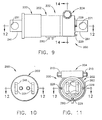
- FIG. 9 is a simplified side view of a remotely releasable support strut according to a further embodiment of the present invention.
- FIG. 10 is a left end view of the support strut of FIG. 9 ;
- FIG. 11 is a right end view of the support strut of FIG. 9 ;
- FIG. 12 is a simplified partial cross-sectional view of the support strut of FIGS. 9-11 showing interior details with the strut in a released (free) condition;
- FIG. 13 is a simplified partial cross-sectional view of the support strut of FIG. 12 , with the strut in a locked condition;
- FIG. 14 is a partial cross-sectional view of a portion of the strut of FIGS. 9-13 .
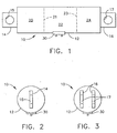
- FIG. 1 is a simplified conceptual side view of remotely releasable support strut 10 according to the present invention.
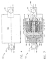
- FIG. 2 is a left side end view of the support strut of FIG. 1.
- FIG. 3 is a right side end view of the support strut of FIG. 1 .
- Support strut 10 has enclosure or body 12, first attachment means or portion 14 and second attachment means or portion 16, respectively at distal ends of body 12.
- Body 12 is shown in highly simplified form and, as will be further explained, one or both of attachment means 14, 16 are intended to couple to internal supports within body 12 and not merely externally to body 12.
- Attachment portion 14 conveniently has hole 15 therein and attachment portion 16 conveniently has hole 17 therein to permit coupling of strut 10 to an external support (not shown) at one end and to a load (not shown) at the other end.
- attachment portions 14, 16 are shown as made up of a stud or shackle with one or more connection holes therein for attachment to the external support and load, this is merely for convenience of explanation and not intended to be limiting.
- any type of connecting arrangement may be used and that the present invention is not limited by the type of connection used, the nature of the connecting portions being used or the support or load to which the strut is attached.
- strut 10 conveniently has at least three functions therein; damper function 20, release function 22 and locking function 24. While these functions are illustrated in FIG. 1 as being arranged in series, this is merely for convenience of explanation and is not essential. One or more of these functions may conveniently be integrated in whole or part with other function(s). What is important is that strut 10 provide at least these three functions 20, 22, 24.
- Strut 10 is intended to be coupled between a support (not shown) and a load (not shown) via coupling or attachment portions 14, 16. Its function is to support the load used under a variety of conditions. For example:
- strut 10 should act as a substantially rigid support while the load is being moved. This condition is referred to as being "locked.” Accordingly, as used herein the words “lock” and “locked” are intended to mean a strut has been placed in a condition in which it is substantially rigid as far as the forces it is intended to withstand are concerned. For example, when strut 10 is used with a spacecraft deployable load, it must resist the inertial forces generated during the launch phase and any subsequent positioning rocket burns. The forces encountered during such activities can be quite high, many times the earth weight of the payload. For example, it is not unusual to require a support strut to withstand a 11340 kg (25,000-pound) inertial force during launch of a spacecraft deployable load.
- the locked condition of the strut must be robust and capable of supporting large inertial forces. While this aspect is particularly important for space deployed systems, the same considerations apply equally well for earthbound or marine applications where large inertial forces can be generated whenever sensitive equipment is being moved.
- the purpose of locking function 24 is to place strut 10 in a locked condition.
- strut 10 should desirably act to some degree as a flexible coupling between support and load after the primary movement of the load has been completed, for example, after a spacecraft deployable load has been placed in orbit.
- damper function 22 As used herein the words “damp”, “damping”, “damper” or “damper function” are intended to refer generally to any arrangement for providing a flexible coupling between attachment portions 14, 16 so that some relative motion thereof is possible. It is desirable that damper function 22 also include some means of cushioning the relative motion to absorb and/or dissipate mechanical energy so that the amount transmitted to or from the load is reduced, that is, so that there is provided some mechanical isolation between support and load. Any and all of these functions are intended to be included in damper function 20. When strut 10 is in a condition where damper function 22 is operative, it is referred to as being "free.”
- strut 10 provides remote release of the locking mechanism, that is, be capable of changing from the locked to the free condition without human intervention.
- strut 10 desirably contains remote release function 22.
- the purpose of remote release function 22 is to unlock the strut after primary movement has been completed so as to place it in a "free" condition where damper function 20 is operative.
- release function 22 is 'soft", that is, that it occurs gradually and is not accompanied by any sudden shock, explosions or breakage of internal supports.
- Electrical plug 30 is provided in body 12 of strut 10 so that remote release function 22 may be electrically activated.
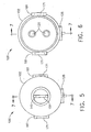
- FIG. 4 is a side view
- FIG. 5 is a left end view
- FIG. 6 is a right end view of support structure or strut 100, similar to strut 10, showing further details.
- Strut 100 has body 102 analogous to body 12 of FIG. 1 , and attachment portions 141, 161 with coupling holes 151, 171 analogous to 14, 16 and 15, 17, respectively, of FIG. 1 .
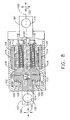
- FIG. 7 is a simplified partial cross-sectional view of support strut 100 of FIGS. 4-6 , showing interior details with the strut in a locked condition.
- FIG. 7 is a view substantially on plane 7-7 indicated in FIGS. 5-6 .
- locking bolts 120 are shown whole rather than in cross-section in FIGS. 7-8 .
- FIG. 8 is a view similar to FIG. 7 but showing strut 100 in the free condition.
- attachment portion 161 is part of or attached to body 102 and attachment portion 141 is part of or attached to internal damper strut ("D-strut") 104.
- D-strut internal damper strut
- surface 105 of D-strut 104 rests against surface 106 of body 102.
- surfaces 105, 106 are spaced apart by gap 109 and D-strut 104 is coupled to body 102 by resilient member 108.
- Resilient member 108 is usefully a spring or bellows or elastomeric cushioning material or a combination thereof. Such materials are well known in the art.
- resilient member 108 provides damper function 20.
- gap 109 separates D-strut 104 and housing 102, and gap 113 separates D-strut 104 and jack-pad 110.
- Spring 111 insures that gap 113 remains open until locking screws 120 are activated.
- Spring 111 is substantially weaker than the spring action of resilient member 108 so gap 109 also remains open in the free condition.
- D-strut 104 and housing 102 are coupled only by resilient member 108, thus allowing attachment portions 141 and 161 to move with respect to each other as indicated by arrows 122.
- the range of motion of damping function 20 in strut 100 is determined by the size of gaps 109, 113 and the geometry of the various parts, and may be varied by the designer to suit a particular need.
- locking function 24 is provided by the combination of D-strut 104, jack-pad 110, compression block 112, locking screws 120 and expansion material 114.
- gap 113 is closed and jack-pad 110 is forced against D-strut 104, which, in turn, is forced against body 102 as gap 109 is closed (see FIG. 7 ).
- Locking screws 120 screw into and out of compression block 112 via threads 116.
- the reaction force created by screws 120 pressing against jack-pad 110 is transmitted to body 102 via expansion material 114.
- Expansion material 114 is firmly coupled to body 102 by joint 118 and to compression block 112 by joint 124.
- Joints 118, 124 may be formed by any convenient means, as for example, but not limited to, mechanical threads or brazing or welding or other means having comparatively high shear strength. Any means can be used provided that it has sufficient shear strength to resist the forces generating during pre-loading and release.
- Locking screws 120 are advanced to place strut 100 in the locked condition ( FIG. 7 ) and backed off to return strut 100 to the free condition ( FIG. 8 ), as for example, for test purposes. While only two locking screws 120 are shown in FIGS. 6-8 , this is merely for convenience of explanation and is not intended to be limiting. The more screws 120, the larger their diameter, the finer their threads and the more robust compression block 112, the greater the stress that strut 100 can withstand in the locked state. Thus, by varying the number and type of locking screws, the properties of strut 100 can be adapted to different loads and different stress conditions associated with launch or other movement.
- Remote release function 24 is provided by expansion material 114 and heater 126.
- Expansion material 114 conveniently has the shape of a hollow cylinder with its longitudinal axis substantially coincident with axis 190 of strut 100.
- Heater 126 is thermally coupled to expansion material 114, in this example, mounted in intimate contact with the inside wall of the expansion material cylinder. However, heater 126 can equally well be mounted in thermal contact with the outside wall of expansion material 114. Either arrangement is useful.
- Heater 126 is electrically coupled to external plug 128 (see FIGS. 5-6 ) whereby electrical current is supplied to energize heater 126. Heater 126 may be energized remotely, that is for example, after a spacecraft deployable system has been launched into orbit or other load placed in an inaccessible location.
- Expansion material 114 is conveniently formed of a Shape Memory Alloy (SMA), such as, for example, a TiNi alloy sold by TiNi Aerospace, San Leandro, CA under the trade name "Nitinol.”
- SMA Shape Memory Alloy
- TiNi alloy sold by TiNi Aerospace, San Leandro, CA under the trade name "Nitinol.”
- Shape Memory Alloys are well known in the art. They have the property, among other things, that when heated to a critical temperature Tc, they undergo a phase transition to another crystalline form with an accompanying large expansion and, for some materials, a large increase in elasticity. This phenomenon can cause the SMA to recover from a mechanically preset state (e.g., to elongate) and remain in that condition after the heat is removed.
- SMA expansion material 114 When locking bolts 120 are tightened to place strut 100 in a locked condition, SMA expansion material 114 is stressed in tension.
- heater 126 When heater 126 is energized to raise the temperature of SMA 114 above its transition point, a large strain occurs at constant stress, that is, SMA 114 significantly elongates, thereby moving compression block 112 to the right in FIGS. 7-8 , reopening gaps 109, 113. This change in shape is retained after heater 126 is de-energized. Thus, strut 100 is returned to the free condition.
- the length of SMA 114 (parallel to axis 190) is selected to provide the amount of deformation desired in order to have gaps 109, 113 of an appropriate size for the particular application.
- the thickness of SMA 114 (perpendicular to axis 190) is selected to withstand the pre-loading force exerted by bolts 120 when strut 100 is placed in the locked condition.
- a pre-load force of ⁇ 25,000 pounds can be placed on strut 100 when locked. That means that strut 100 can withstand a reaction force of ⁇ 25,000 pounds during system movement, e.g., launch.
- SMA 114 of Nitinol having a length of about 7.7 com, an outer diameter of about 6.4 cm and a wall thickness of about 1.5 cm, can increase in length by about 2.3 mm when heated to its phase transition temperature by heater 126. This is sufficient in this particular application to restore gaps 109, 113 substantially to at least their prelock, e.g., "free" values of about 1 mm each.
- Jack-pad 110 is conveniently formed of Nitronic 60, and compression block 112, D-strut 104 and housing 102 are conveniently of Ti, although other materials well known in the art can also be used.
- FIG. 9 is a side view
- FIG. 10 is a left end view
- FIG. 11 is a right end view of support structure or strut 200, similar to strut 10 but according to a further embodiment.
- Strut 200 has body 202 analogous to body 12 of FIG. 1 , and attachment portions 241, 261 with coupling holes 251, 271 analogous to 14, 16 and 15, 17, respectively, of FIG. 1 .
- FIGS. 12 , 13 are simplified partial cross-sectional views of support strut 200, analogous to FIGS. 8 , 7 respectively, and along plane 12-12 shown in FIGS. 9-11 .
- FIG. 12 shows strut 200 in the free or released condition
- FIG. 13 shows strut 200 in the locked condition.
- FIG. 14 is a simplified partial cross-sectional view of a portion of support strut 200 of FIGS. 9-13 along plane 14-14 in FIGS. 9 , 12-13 , showing further details.
- Support strut 200 has damper function region 220 analogous to function 20, release function region 222 analogous to function 22 and locking mechanism region 224 analogous to function 24 of strut 10 of FIG. 1 .
- Locking mechanism 224 comprises worm gear pre-loader 204 partially visible in FIGS. 12-14 .
- Worm gear pre-loader 204 includes worm 206 engaging pinion worm gear 208.
- Pinion worm gear 208 is rotationally held between portions 228 and 230 of body 202.
- Body portions 228, 230 are conveniently joined to portion 272 of body 202 by bolts 229.
- Worm 206 has one or more end region(s) 210 to which a torque wrench can be applied.
- Turning worm 206 causes pinion gear 208 to rotate with a mechanical advantage determined by the number of teeth on pinion gear 208.
- Located within and axially concentric with pinion gear 208 is sleeve 212 with spline 213 that rotates with pinion 208.
- Inner portions 216, 218 of splined sleeve 214 are threaded, portion 216 being a right-hand thread and portion 218 being a left-hand thread (or vice-versa). Threaded portion 216 of sleeve 212 engages matching threads on end plug 226 which is fixed to end region 230 of body 202 by attachment means 231. Located within end plug 226 is spring 227 that engages cylindrical plug 232. Cylindrical plug 232 is concentric with and slides over a portion of end plug 226 in a manner that prevents mutual rotation thereof.
- Spline or polygonal shape 225 is used in the intersecting region of plugs 226, 232 to permit axial sliding (i.e., parallel to axis 214) but prevent rotation of cylindrical plug 232 relative to end plug 226.
- Threaded portion 218 of sleeve 212 engages matching threads on cylindrical plug 232.
- Plug 232 has cap 234 fixed thereon by attachment means 233. Taken together, plug 232 and cap 234 are referred to collectively as jack-pad 236.
- pinion gear 208 rotates
- splined sleeve 212 rotates and moves along threads 216 in a direction parallel to axis 214 of strut 200.
- jack-pad 236 moves to the right on threads 218 but by twice the distance which sleeve 212 moves.
- jack-pad 236 and concentric yoke 238 are spaced apart by first gap 237 (see FIG. 12 ).
- jack-pad 236 moves to the right closing first gap 237 and engaging yoke 238.
- Yoke 238 is fixed on mandrel 240 by attachment means 239.
- Concentrically surrounding mandrel 240 is expansion material 242 with concentric heater 244, analogous to expansion material and heater 114,126 of strut 100 in FIGS 7-8 .
- Mandrel cap 246 is attached to mandrel 240 by bolt 248.
- the dimensions and arrangement of mandrel 240, expansion material 242, mandrel cap 246 and bolt 248 are chosen so that expansion material 242 is preferably under axially directed compression, but this is not essential. However, it is important that expansion material 242 at least fit snugly between mandrel 240 and mandrel cap 246 in the axial direction.
- Mandrel cap 246 is coupled to flex mount holder 250 by attachment means 247.
- Body 202 has interior portion 256 that is coupled to D-strut 254 by resilient members 258, 260. It is resilient members 258, 260, in conjunction with D-strut 254 and body portion 256, that comprise damping function region 220 for providing damping function 20 in strut 200.
- resilient members 258, 260 are annular, fluid-filled bellows springs that are compressible in the direction of axis 214. Such fluid filled bellows springs are desirably coupled by a narrow tube (not shown) to allow fluid to flow from the bellows being axially compressed (e.g., 258 in FIG. 13 ) into the bellows being axially stretched (e.g., 260 in FIG. 13 ), but this is not essential.
- various other arrangements may be used, including but not limited to, rubber and/or plastic materials, springs, or any other arrangement that provides both a spring action and, desirably, viscous action of some kind to dissipate vibrational energy.
- Body 202 has skirt portion 262 coupled by attachment means 263 to body portion 272.
- gap 265 exists between end 266 of skirt 262 and mating surface 268 of end plate 252.
- End plate 252 is also coupled to body portion 272 by spring 270.
- Spring 270 conveniently has a rectangular cross-section and extends from end plate 252 to body portion 272.
- Spring 270 can be machined as a part of end plate 252 and attached to body portion 272 by joining means (not shown).
- spring 270 can be a separate part joined to end plate 252 and body portion 272 by, for example, welding, brazing, threaded joints, or a combination thereof.
- the exact method of attachment is not critical and is omitted from FIGS. 12-13 for simplicity.
- Locking mechanism 224 with worm gear pre-loader 204 provides great mechanical advantage and allows a large pre-load force to be placed on strut 200, as for example, more than 25,000 pounds by a single wrench on worm gear ends 210 and with much reduced wrench torque, for example, - 70 foot-pounds. By reversing the direction of worm drive 204, this strut pre-load force may be relieved for testing and then re-applied without damage to strut 200 and without having to change or replace any interior parts thereof.
- expansion material 242 is, in the preferred embodiment, placed in compression during assembly of D-strut 254.
- This initial compressive pre-load force on expansion material 242 may or may not be overcome by the tension strut pre-loading through locking mechanism 224.
- expansion material 242 undergoes a phase transformation thereby significantly increasing its length. It does this against the restraining resistance of mandrel portion 240 of D-strut 254.
- the material and dimensions of mandrel portion 240 and expansion material 242 should be chosen so that the expansion force of expansion material 242 plastically stretches mandrel portion 240.
- Strut 200 is released by heating expansion material 242 with heater 244 to plastically deform D-strut 254 without fracture. As with strut 100, this release is a gradual and quiet process, without the sudden snap or explosive detachment encountered in the prior art. The speed of the release step is determined generally by the heating time-constant of heater 244 and expansion material 242 mounted on D-strut 254. Electricity is supplied to heater 244 via plug 280.
- Joints 231, 233, 239, 247, 263 in strut 200 may be formed by any convenient means, as for example and not intended to be limiting, mechanical threads or the like, brazing and welding or the like, or other means well known in the art having sufficient shear strength for the application.
- Persons of skill in the art will also understand that the assemblies depicted in connection with FIGS. 1-14 are intended to illustrate the principles of the invention and not be shop drawings. Differently shaped components and more or fewer assembly joints may be desirable to facilitate struts embodying the present invention. Further it will be appreciated that the order of assembly of parts of the struts may be varied to suit particular manufacturing needs and applications. Persons of skill in the art will know how to do this based on the description herein and the accompanying drawings.
Description
- The present invention generally relates to equipment support struts that can be locked and released manually or remotely, and more particularly, supports struts useable in connection with remotely deployable systems.
- Many electronic, optical and mechanical systems that are fragile but which must be moved require support struts capable of being locked during movement of the system and released when the system is in place so that associated anti-vibration and other isolation elements are free to protect the system from subsequent mechanical stress. The problem of providing such a lockable and releasable strut is particularly difficult when the system is remotely deployable, as for example, when used in spacecraft. During launch of spacecraft deployable systems, the payload can be subjected to large mechanical forces and must be restrained to avoid damage. However, once the payload is in orbit it is no longer human accessible. Thus, conventional man-releasable struts cannot be used.
- In the prior art, it has been common to overcome this lack of access by using remotely triggered release mechanisms such as explosive bolts or the like that fracture or deform parts of the support structure to cause release. While such mechanisms can be fired remotely by radio or computer command and are effective in releasing a pre-loaded (locked) support strut, they can impart significant shock to the payload when activated, thereby increasing the risk of harm to a fragile system. A further limitation of such prior art approaches is that they are often difficult or impossible to test prior to launch, that is, alternatively placed in a locked or released condition.
- Accordingly, a need continues to exist for supports that can be locked and released manually or remotely, and especially for supports useable in connection with remotely deployable systems. In addition, it is desirable to provide a support structure that can be locked and released multiple times for test purposes. It is further desirable that remote release of the support be accomplished without significant shock to the support or its payload so that damage to fragile components of the system being supported is avoided. Furthermore, other desirable features and characteristics of the present invention will become apparent from the subsequent detailed description of the invention and the appended claims, taken in conjunction with the accompanying drawings and this background of the invention.
-
WO 03/058091 -
US 5,060,888 discloses a temporary linking device especially for an artificial satellite lengthening piece. Also disclosed is a method for freeing such a link. -
US 6,508.437 discloses a launch lock for spacecraft payloads and is considered as the closest prior art. - According to the present invention there is provided a support strut having opposed distal ends, comprising: a damping section coupled between the ends and having at least one gap therein when the strut is unlocked; a locking section coupled between the ends for closing the at least one gap by applying stress to a portion of the damping section through a force transmitting member; a releasing section coupled in parallel with the force transmitting member, the releasing section comprising a shape memory alloy and heater therefore such that heating the shape memory alloy substantially relieves the stress in the force transmitting member; and characterised in that the locking section comprises a turnbuckle arrangement.
- A method is provided for locking and releasing ends of a support strut coupled between a mounting platform and a load and having the above-noted elements. The method comprises applying a force to the damper section using the locking section to lock the strut and heating the shape memory alloy to relieve the force applied to the damper section, thereby releasing the strut. In a preferred embodiment, the force is applied using a worm drive turnbuckle arrangement. Heating can be remotely actuated.
- The present invention will hereinafter be described in conjunction with the following drawing figures, wherein like numerals denote like elements, and
-
FIG. 1 is a simplified conceptual side view of a remotely releasable support strut according to the present invention; -
FIG. 2 is a left end view of the support strut ofFIG. 1 ; -
FIG. 3 is a right end view of the support strut ofFIG. 1 ; -
FIG. 4 is a simplified side view of a remotely releasable support strut according to the present invention showing further details; -
FIG. 5 is a left end view of the support strut ofFIG. 4 ; -
FIG. 6 is a right end view of the support strut ofFIG. 4 ; -
FIG. 7 is a simplified partial cross-sectional view of the support strut ofFIGS. 4-6 showing interior details with the strut in a locked condition; -
FIG. 8 is a simplified partial cross-sectional view similar toFIG. 7 but with the strut ofFIGS. 4-6 in a released condition; -
FIG. 9 is a simplified side view of a remotely releasable support strut according to a further embodiment of the present invention; -
FIG. 10 is a left end view of the support strut ofFIG. 9 ; -
FIG. 11 is a right end view of the support strut ofFIG. 9 ; -
FIG. 12 is a simplified partial cross-sectional view of the support strut ofFIGS. 9-11 showing interior details with the strut in a released (free) condition; -
FIG. 13 is a simplified partial cross-sectional view of the support strut ofFIG. 12 , with the strut in a locked condition; and -
FIG. 14 is a partial cross-sectional view of a portion of the strut ofFIGS. 9-13 . - The following detailed description of the invention is merely exemplary in nature and is not intended to limit the invention or the application and uses of the invention. Furthermore, there is no intention to be bound by any theory presented in the preceding background of the invention or the following detailed description of the invention.
- While the present invention is described by way of a support structure or strut that is particularly adapted for use in connection with spacecraft deployable systems, those of skill in the art will understand that this is merely for convenience of explanation and not intended to be limiting, and that the present invention is useful and applicable to terrestrial (land and marine) and aircraft based systems as well as space based systems.
-
FIG. 1 is a simplified conceptual side view of remotelyreleasable support strut 10 according to the present invention.FIG. 2 is a left side end view of the support strut ofFIG. 1. FIG. 3 is a right side end view of the support strut ofFIG. 1 .Support strut 10 has enclosure orbody 12, first attachment means orportion 14 and second attachment means orportion 16, respectively at distal ends ofbody 12.Body 12 is shown in highly simplified form and, as will be further explained, one or both of attachment means 14, 16 are intended to couple to internal supports withinbody 12 and not merely externally tobody 12.Attachment portion 14 conveniently has hole 15 therein andattachment portion 16 conveniently hashole 17 therein to permit coupling ofstrut 10 to an external support (not shown) at one end and to a load (not shown) at the other end. Whileattachment portions - As indicated by
dashed lines strut 10 conveniently has at least three functions therein;damper function 20,release function 22 andlocking function 24. While these functions are illustrated inFIG. 1 as being arranged in series, this is merely for convenience of explanation and is not essential. One or more of these functions may conveniently be integrated in whole or part with other function(s). What is important is thatstrut 10 provide at least these threefunctions -
Strut 10 is intended to be coupled between a support (not shown) and a load (not shown) via coupling orattachment portions - First,
strut 10 should act as a substantially rigid support while the load is being moved. This condition is referred to as being "locked." Accordingly, as used herein the words "lock" and "locked" are intended to mean a strut has been placed in a condition in which it is substantially rigid as far as the forces it is intended to withstand are concerned. For example, whenstrut 10 is used with a spacecraft deployable load, it must resist the inertial forces generated during the launch phase and any subsequent positioning rocket burns. The forces encountered during such activities can be quite high, many times the earth weight of the payload. For example, it is not unusual to require a support strut to withstand a 11340 kg (25,000-pound) inertial force during launch of a spacecraft deployable load. Thus, the locked condition of the strut must be robust and capable of supporting large inertial forces. While this aspect is particularly important for space deployed systems, the same considerations apply equally well for earthbound or marine applications where large inertial forces can be generated whenever sensitive equipment is being moved. The purpose of lockingfunction 24 is to placestrut 10 in a locked condition. - Second, strut 10 should desirably act to some degree as a flexible coupling between support and load after the primary movement of the load has been completed, for example, after a spacecraft deployable load has been placed in orbit. This is a purpose of
damper function 22. As used herein the words "damp", "damping", "damper" or "damper function" are intended to refer generally to any arrangement for providing a flexible coupling betweenattachment portions damper function 22 also include some means of cushioning the relative motion to absorb and/or dissipate mechanical energy so that the amount transmitted to or from the load is reduced, that is, so that there is provided some mechanical isolation between support and load. Any and all of these functions are intended to be included indamper function 20. Whenstrut 10 is in a condition wheredamper function 22 is operative, it is referred to as being "free." - Third, a feature of
strut 10 is that it provide remote release of the locking mechanism, that is, be capable of changing from the locked to the free condition without human intervention. Hence, strut 10 desirably containsremote release function 22. The purpose ofremote release function 22 is to unlock the strut after primary movement has been completed so as to place it in a "free" condition wheredamper function 20 is operative. A further feature of the present invention is thatrelease function 22 is 'soft", that is, that it occurs gradually and is not accompanied by any sudden shock, explosions or breakage of internal supports.Electrical plug 30 is provided inbody 12 ofstrut 10 so thatremote release function 22 may be electrically activated. -
FIG. 4 is a side view,FIG. 5 is a left end view, andFIG. 6 is a right end view of support structure or strut 100, similar to strut 10, showing further details.Strut 100 hasbody 102 analogous tobody 12 ofFIG. 1 , andattachment portions coupling holes FIG. 1 .FIG. 7 is a simplified partial cross-sectional view ofsupport strut 100 ofFIGS. 4-6 , showing interior details with the strut in a locked condition.FIG. 7 is a view substantially on plane 7-7 indicated inFIGS. 5-6 . For simplicity of illustration, lockingbolts 120 are shown whole rather than in cross-section inFIGS. 7-8 .FIG. 8 is a view similar toFIG. 7 but showingstrut 100 in the free condition. - Referring now to
FIGS. 7-8 ,attachment portion 161 is part of or attached tobody 102 andattachment portion 141 is part of or attached to internal damper strut ("D-strut") 104. In the locked condition,surface 105 of D-strut 104 rests againstsurface 106 ofbody 102. In the free condition, surfaces 105, 106 are spaced apart bygap 109 and D-strut 104 is coupled tobody 102 byresilient member 108.Resilient member 108 is usefully a spring or bellows or elastomeric cushioning material or a combination thereof. Such materials are well known in the art. In combination with D-strut 104 andbody 102,resilient member 108 providesdamper function 20. - In the free condition (see
FIG. 8 )gap 109 separates D-strut 104 andhousing 102, andgap 113 separates D-strut 104 and jack-pad 110.Spring 111 insures thatgap 113 remains open until lockingscrews 120 are activated.Spring 111 is substantially weaker than the spring action ofresilient member 108 sogap 109 also remains open in the free condition. In the free condition, D-strut 104 andhousing 102 are coupled only byresilient member 108, thus allowingattachment portions arrows 122. The range of motion of dampingfunction 20 instrut 100 is determined by the size ofgaps - In
strut 100, lockingfunction 24 is provided by the combination of D-strut 104, jack-pad 110,compression block 112, lockingscrews 120 andexpansion material 114. When locking screws 120 are advanced,gap 113 is closed and jack-pad 110 is forced against D-strut 104, which, in turn, is forced againstbody 102 asgap 109 is closed (seeFIG. 7 ). Lockingscrews 120 screw into and out ofcompression block 112 viathreads 116. The reaction force created byscrews 120 pressing against jack-pad 110 is transmitted tobody 102 viaexpansion material 114.Expansion material 114 is firmly coupled tobody 102 by joint 118 and to compression block 112 by joint 124.Joints - Locking
screws 120 are advanced to placestrut 100 in the locked condition (FIG. 7 ) and backed off to returnstrut 100 to the free condition (FIG. 8 ), as for example, for test purposes. While only two lockingscrews 120 are shown inFIGS. 6-8 , this is merely for convenience of explanation and is not intended to be limiting. The more screws 120, the larger their diameter, the finer their threads and the morerobust compression block 112, the greater the stress that strut 100 can withstand in the locked state. Thus, by varying the number and type of locking screws, the properties ofstrut 100 can be adapted to different loads and different stress conditions associated with launch or other movement. -
Remote release function 24 is provided byexpansion material 114 andheater 126.Expansion material 114 conveniently has the shape of a hollow cylinder with its longitudinal axis substantially coincident withaxis 190 ofstrut 100.Heater 126 is thermally coupled toexpansion material 114, in this example, mounted in intimate contact with the inside wall of the expansion material cylinder. However,heater 126 can equally well be mounted in thermal contact with the outside wall ofexpansion material 114. Either arrangement is useful.Heater 126 is electrically coupled to external plug 128 (seeFIGS. 5-6 ) whereby electrical current is supplied to energizeheater 126.Heater 126 may be energized remotely, that is for example, after a spacecraft deployable system has been launched into orbit or other load placed in an inaccessible location. -
Expansion material 114 is conveniently formed of a Shape Memory Alloy (SMA), such as, for example, a TiNi alloy sold by TiNi Aerospace, San Leandro, CA under the trade name "Nitinol." Shape Memory Alloys are well known in the art. They have the property, among other things, that when heated to a critical temperature Tc, they undergo a phase transition to another crystalline form with an accompanying large expansion and, for some materials, a large increase in elasticity. This phenomenon can cause the SMA to recover from a mechanically preset state (e.g., to elongate) and remain in that condition after the heat is removed. - When locking
bolts 120 are tightened to placestrut 100 in a locked condition,SMA expansion material 114 is stressed in tension. Whenheater 126 is energized to raise the temperature ofSMA 114 above its transition point, a large strain occurs at constant stress, that is,SMA 114 significantly elongates, thereby movingcompression block 112 to the right inFIGS. 7-8 , reopeninggaps heater 126 is de-energized. Thus, strut 100 is returned to the free condition. The length of SMA 114 (parallel to axis 190) is selected to provide the amount of deformation desired in order to havegaps bolts 120 whenstrut 100 is placed in the locked condition. - By way of example, and not intended to be limiting, with four locking
bolts 120 of 3/8 x 24 size torqued to ∼ 50 foot-pounds each, a pre-load force of ∼25,000 pounds can be placed onstrut 100 when locked. That means thatstrut 100 can withstand a reaction force of ∼25,000 pounds during system movement, e.g., launch.SMA 114 of Nitinol having a length of about 7.7 com, an outer diameter of about 6.4 cm and a wall thickness of about 1.5 cm, can increase in length by about 2.3 mm when heated to its phase transition temperature byheater 126. This is sufficient in this particular application to restoregaps pad 110 is conveniently formed of Nitronic 60, andcompression block 112, D-strut 104 andhousing 102 are conveniently of Ti, although other materials well known in the art can also be used. -
FIG. 9 is a side view,FIG. 10 is a left end view, andFIG. 11 is a right end view of support structure or strut 200, similar to strut 10 but according to a further embodiment.Strut 200 hasbody 202 analogous tobody 12 ofFIG. 1 , andattachment portions coupling holes FIG. 1 .FIGS. 12 ,13 are simplified partial cross-sectional views ofsupport strut 200, analogous toFIGS. 8 ,7 respectively, and along plane 12-12 shown inFIGS. 9-11 .FIG. 12 shows strut 200 in the free or released condition andFIG. 13 shows strut 200 in the locked condition. For simplicity of illustration,attachment bolts FIGS. 12 - 13 are shown whole rather than in cross-section. Attachment portions orregions holes strut 200 perform the same function as described in connection withstruts FIGS. 1-8 .FIG. 14 is a simplified partial cross-sectional view of a portion ofsupport strut 200 ofFIGS. 9-13 along plane 14-14 inFIGS. 9 ,12-13 , showing further details.Support strut 200 hasdamper function region 220 analogous to function 20,release function region 222 analogous to function 22 andlocking mechanism region 224 analogous to function 24 ofstrut 10 ofFIG. 1 . -
Locking mechanism 224 comprisesworm gear pre-loader 204 partially visible inFIGS. 12-14 .Worm gear pre-loader 204 includesworm 206 engagingpinion worm gear 208.Pinion worm gear 208 is rotationally held betweenportions body 202.Body portions portion 272 ofbody 202 bybolts 229.Worm 206 has one or more end region(s) 210 to which a torque wrench can be applied. Turningworm 206 causespinion gear 208 to rotate with a mechanical advantage determined by the number of teeth onpinion gear 208. Located within and axially concentric withpinion gear 208 issleeve 212 withspline 213 that rotates withpinion 208.Inner portions 216, 218 ofsplined sleeve 214 are threaded, portion 216 being a right-hand thread andportion 218 being a left-hand thread (or vice-versa). Threaded portion 216 ofsleeve 212 engages matching threads onend plug 226 which is fixed to endregion 230 ofbody 202 by attachment means 231. Located withinend plug 226 isspring 227 that engagescylindrical plug 232.Cylindrical plug 232 is concentric with and slides over a portion ofend plug 226 in a manner that prevents mutual rotation thereof. Spline orpolygonal shape 225 is used in the intersecting region ofplugs cylindrical plug 232 relative to endplug 226. Threadedportion 218 ofsleeve 212 engages matching threads oncylindrical plug 232.Plug 232 hascap 234 fixed thereon by attachment means 233. Taken together, plug 232 andcap 234 are referred to collectively as jack-pad 236. - The combination of
pinion gear 208,sleeve 212, end-plug 226 and jack-pad 236 form a turn-buckle. Referring toFIGS. 12-13 , aspinion gear 208 rotates,splined sleeve 212 rotates and moves along threads 216 in a direction parallel toaxis 214 ofstrut 200. At the same time assleeve 212 is moving, for example to the right inFIG. 13 , jack-pad 236 moves to the right onthreads 218 but by twice the distance whichsleeve 212 moves. In the free (released) state, jack-pad 236 andconcentric yoke 238 are spaced apart by first gap 237 (seeFIG. 12 ). As worm-gear pre-loader 204 is actuated by rotatingworm 206 in the appropriate direction, jack-pad 236 moves to the right closingfirst gap 237 and engagingyoke 238. -
Yoke 238 is fixed onmandrel 240 by attachment means 239. Concentrically surroundingmandrel 240 is expansion material 242 with concentric heater 244, analogous to expansion material and heater 114,126 ofstrut 100 inFIGS 7-8 .Mandrel cap 246 is attached tomandrel 240 bybolt 248. The dimensions and arrangement ofmandrel 240, expansion material 242,mandrel cap 246 and bolt 248 are chosen so that expansion material 242 is preferably under axially directed compression, but this is not essential. However, it is important that expansion material 242 at least fit snugly betweenmandrel 240 andmandrel cap 246 in the axial direction.Mandrel cap 246 is coupled to flexmount holder 250 by attachment means 247. Taken collectively,mandrel 240,mandrel cap 246 and flexmount holder 250 comprise D-strut 254. D-strut 254 is coupled toend plate 252 bybolts 253 or other suitable attachment means. Mountingportion 241 is coupled to or a part ofend plate 252. -
Body 202 hasinterior portion 256 that is coupled to D-strut 254 byresilient members resilient members strut 254 andbody portion 256, that comprise dampingfunction region 220 for providing dampingfunction 20 instrut 200. In the preferred embodiment,resilient members axis 214. Such fluid filled bellows springs are desirably coupled by a narrow tube (not shown) to allow fluid to flow from the bellows being axially compressed (e.g., 258 inFIG. 13 ) into the bellows being axially stretched (e.g., 260 inFIG. 13 ), but this is not essential. As noted in conjunction withresilient members 105 inFIGS. 7-8 , various other arrangements may be used, including but not limited to, rubber and/or plastic materials, springs, or any other arrangement that provides both a spring action and, desirably, viscous action of some kind to dissipate vibrational energy. -
Body 202 hasskirt portion 262 coupled by attachment means 263 tobody portion 272. In the free state,gap 265 exists betweenend 266 ofskirt 262 andmating surface 268 ofend plate 252.End plate 252 is also coupled tobody portion 272 byspring 270.Spring 270 conveniently has a rectangular cross-section and extends fromend plate 252 tobody portion 272.Spring 270 can be machined as a part ofend plate 252 and attached tobody portion 272 by joining means (not shown). Alternatively,spring 270 can be a separate part joined to endplate 252 andbody portion 272 by, for example, welding, brazing, threaded joints, or a combination thereof. The exact method of attachment is not critical and is omitted fromFIGS. 12-13 for simplicity. Whenstrut 200 is in the free state, relative motion between attachment means 241, 261 as shown byarrows 274 is constrained and damped by the combination ofspring 270 andresilient members worm gear pre-loader 204 is turned,gap 237 is closed and D-strut 254 is placed in tension. This in turn causessurface 268 ofend plate 252 to be pulled into contact withend surface 266 ofskirt portion 262closing gap 265. In the locked state,gaps FIG. 13 ). -
Locking mechanism 224 withworm gear pre-loader 204 provides great mechanical advantage and allows a large pre-load force to be placed onstrut 200, as for example, more than 25,000 pounds by a single wrench on worm gear ends 210 and with much reduced wrench torque, for example, - 70 foot-pounds. By reversing the direction ofworm drive 204, this strut pre-load force may be relieved for testing and then re-applied without damage to strut 200 and without having to change or replace any interior parts thereof. - Remote release is provided in the same manner as for
strut 100 except that in this case, expansion material 242 is, in the preferred embodiment, placed in compression during assembly of D-strut 254. This initial compressive pre-load force on expansion material 242 may or may not be overcome by the tension strut pre-loading throughlocking mechanism 224. In either case, when heater 244 is activated, expansion material 242 undergoes a phase transformation thereby significantly increasing its length. It does this against the restraining resistance ofmandrel portion 240 of D-strut 254. Thus, the material and dimensions ofmandrel portion 240 and expansion material 242 should be chosen so that the expansion force of expansion material 242 plastically stretchesmandrel portion 240. For this reason, TiNi is preferred for expansion material 242 and type A-286 stainless steel is preferred formandrel portion 240. Type A-286 stainless steel has a large plastic limit, that is, it continues to plastically deform long after lesser materials might have destructively fractured.Strut 200 is released by heating expansion material 242 with heater 244 to plastically deform D-strut 254 without fracture. As withstrut 100, this release is a gradual and quiet process, without the sudden snap or explosive detachment encountered in the prior art. The speed of the release step is determined generally by the heating time-constant of heater 244 and expansion material 242 mounted on D-strut 254. Electricity is supplied to heater 244 viaplug 280. -
Joints strut 200 may be formed by any convenient means, as for example and not intended to be limiting, mechanical threads or the like, brazing and welding or the like, or other means well known in the art having sufficient shear strength for the application. Persons of skill in the art will also understand that the assemblies depicted in connection withFIGS. 1-14 are intended to illustrate the principles of the invention and not be shop drawings. Differently shaped components and more or fewer assembly joints may be desirable to facilitate struts embodying the present invention. Further it will be appreciated that the order of assembly of parts of the struts may be varied to suit particular manufacturing needs and applications. Persons of skill in the art will know how to do this based on the description herein and the accompanying drawings. - While at least one exemplary embodiment has been presented in the foregoing detailed description of the invention, it should be appreciated that a vast number of variations exist. It should also be appreciated that the exemplary embodiment or exemplary embodiments are only examples, and are not intended to limit the scope, applicability, or configuration of the invention in any way. Rather, the foregoing detailed description will provide those skilled in the art with a convenient road map for implementing an exemplary embodiment of the invention. It being understood that various changes may be made in the function and arrangement of elements described in an exemplary embodiment without departing from the scope of the invention as set forth in the appended claims.
Claims (11)
- A support strut (200) having opposed distal ends, comprising:a damping section (220) coupled between the ends and having at least one gap (237, 265) therein when the strut (200) is unlocked;a locking section (224) coupled between the ends for closing the at least one gap (237, 265) by applying stress to a portion of the damping section (220) through a force transmitting member (229);a releasing section coupled in parallel with the force transmitting member, the releasing section comprising a shape memory alloy and heater (244) therefore such that heating the shape memory alloy substantially relieves the stress in the force transmitting member;the locking section (224) comprising a turnbuckle arrangement (208, 212, 226, 236) for applying stress to the force transmitting member (229).
- The strut (200) of claim 1, wherein the shape memory alloy has an approximately cylindrical shape and is substantially coaxial with the force transmitting member (229).
- The strut (200) of claim 1, wherein the locking section turnbuckle arrangement comprises a worm and pinion gear arrangement (206, 208) for applying stress to the force transmitting member (229).
- The strut (200) of claim 3, wherein the pinion gear (208) drives a rotating and sliding sleeve (212) having opposite pitch threads on the interior thereof.
- The strut (200) of claim 4, wherein the opposite pitch threads comprise a first portion with a first pitch and a second portion with opposite pitch and wherein the first portion engage a first threaded device fixed with respect to one end and the second portion engage a second threaded device moveable with respect to the one end.
- The strut (200) of claim 5, wherein the first and second devices are coupled so that they slide but do not rotate with respect to each other.
- The strut (200) of any preceding claim, wherein the heater (244) is actuated remotely.
- The strut (200) of any preceding claim, further comprising a spring (270) coupling the ends, the spring (270) being compressed to a limit when the strut (200) is locked and not compressed to the limit when the strut (200) is unlocked.
- A method for locking and releasing a support strut between a platform and a load, the support strut having a first end for attachment to the platform and a second end for attachment to the load, the support strut having a damper section (220) coupling the first and second ends, a locking section (224) between the damper section (220) and one end for applying force to the damper section (220) and a releasing section containing a shape memory alloy in parallel with a portion of the locking section (224), the method comprising:applying a force to the damper section (220) using the locking section (224) to lock the support strut;heating the shape memory alloy to relieve the force applied to the damper section, thereby releasing the support strut; and characterised in thatthe applying step comprises using a turnbuckle arrangement (208, 212, 226, 236) to apply force to the damper section (220).
- The method of claim 9, wherein the heating step comprises heating the shape memory alloy to cause the elongation thereof without fracture of a portion of the support strut.
- The method of claim 9, wherein the heating step comprises heating the shape memory alloy to a phase change transition.
Applications Claiming Priority (3)
| Application Number | Priority Date | Filing Date | Title |
|---|---|---|---|
| US396024 | 1982-07-07 | ||
| US10/396,024 US6920966B2 (en) | 2003-03-24 | 2003-03-24 | Remotely releasable support strut |
| PCT/US2004/008890 WO2004108532A1 (en) | 2003-03-24 | 2004-03-24 | Remotely releasable support strut |
Publications (2)
| Publication Number | Publication Date |
|---|---|
| EP1606164A1 EP1606164A1 (en) | 2005-12-21 |
| EP1606164B1 true EP1606164B1 (en) | 2009-04-29 |
Family
ID=33449570
Family Applications (1)
| Application Number | Title | Priority Date | Filing Date |
|---|---|---|---|
| EP04749423A Expired - Fee Related EP1606164B1 (en) | 2003-03-24 | 2004-03-24 | Remotely releasable support strut |
Country Status (5)
| Country | Link |
|---|---|
| US (1) | US6920966B2 (en) |
| EP (1) | EP1606164B1 (en) |
| JP (1) | JP4607115B2 (en) |
| DE (1) | DE602004020877D1 (en) |
| WO (1) | WO2004108532A1 (en) |
Families Citing this family (32)
| Publication number | Priority date | Publication date | Assignee | Title |
|---|---|---|---|---|
| US7422403B1 (en) * | 2003-10-23 | 2008-09-09 | Tini Alloy Company | Non-explosive releasable coupling device |
| US20050205364A1 (en) * | 2004-03-12 | 2005-09-22 | Browne Alan L | Variable resistance strut assemblies and articles containing the same |
| DE602005025321D1 (en) * | 2004-03-25 | 2011-01-27 | Lord Corp | ON-OFF DAMPER SYSTEM, ESPECIALLY FOR WASHING MACHINE |
| US7632361B2 (en) * | 2004-05-06 | 2009-12-15 | Tini Alloy Company | Single crystal shape memory alloy devices and methods |
| US7763342B2 (en) | 2005-03-31 | 2010-07-27 | Tini Alloy Company | Tear-resistant thin film methods of fabrication |
| WO2008030797A2 (en) * | 2006-09-06 | 2008-03-13 | Telezygology, Inc. | Locking strut |
| US8349099B1 (en) | 2006-12-01 | 2013-01-08 | Ormco Corporation | Method of alloying reactive components |
| WO2008092028A1 (en) | 2007-01-25 | 2008-07-31 | Tini Alloy Company | Frangible shape memory alloy fire sprinkler valve actuator |
| US8584767B2 (en) | 2007-01-25 | 2013-11-19 | Tini Alloy Company | Sprinkler valve with active actuation |
| US8973724B2 (en) * | 2007-07-17 | 2015-03-10 | Honeywell International Inc. | Vibration isolators and isolation systems |
| US8007674B2 (en) | 2007-07-30 | 2011-08-30 | Tini Alloy Company | Method and devices for preventing restenosis in cardiovascular stents |
| US8556969B2 (en) | 2007-11-30 | 2013-10-15 | Ormco Corporation | Biocompatible copper-based single-crystal shape memory alloys |
| US8382917B2 (en) | 2007-12-03 | 2013-02-26 | Ormco Corporation | Hyperelastic shape setting devices and fabrication methods |
| US7842143B2 (en) | 2007-12-03 | 2010-11-30 | Tini Alloy Company | Hyperelastic shape setting devices and fabrication methods |
| JP5121064B2 (en) * | 2008-08-19 | 2013-01-16 | 株式会社Ihiエアロスペース | Detonation system |
| US7927375B2 (en) * | 2008-09-12 | 2011-04-19 | Doty Keith L | Dynamic six-degrees-of-freedom intervertebral spinal disc prosthesis |
| US8091481B1 (en) | 2009-05-01 | 2012-01-10 | Floyd Brian A | Gas strut separation for staged rocket |
| FR2947808B1 (en) * | 2009-07-09 | 2011-12-09 | Astrium Sas | SOFT LINEAR SEPARATION DEVICE OF A FIRST PART AND A SECOND PART |
| US7784773B1 (en) | 2009-08-04 | 2010-08-31 | Itt Manufacturing Enterprises, Inc. | Isolator useful for in-line mounting with a strut |
| US8678323B2 (en) * | 2012-02-28 | 2014-03-25 | Honeywell International Inc. | Launch lock assemblies including axial gap amplification devices and spacecraft isolation systems including the same |
| US10124197B2 (en) | 2012-08-31 | 2018-11-13 | TiNi Allot Company | Fire sprinkler valve actuator |
| US11040230B2 (en) | 2012-08-31 | 2021-06-22 | Tini Alloy Company | Fire sprinkler valve actuator |
| US8690180B1 (en) | 2013-03-08 | 2014-04-08 | HG Aircraft Products LLC | Towing adapter |
| US10669048B1 (en) | 2017-06-15 | 2020-06-02 | United Launch Alliance, L.L.C. | Mechanism for increasing jettison clearance |
| US10451139B2 (en) | 2017-11-30 | 2019-10-22 | Honeywell International Inc. | Damping coefficient-regulating inductive heating systems and isolator assemblies including the same |
| US10815011B2 (en) | 2018-01-05 | 2020-10-27 | Planet Labs, Inc. | Restraint system for deployment of a feature on a satellite |
| FR3081945B1 (en) * | 2018-05-31 | 2020-09-18 | Arianegroup Sas | ELECTROMECHANICAL SPONCTUAL SEPARATION SYSTEM |
| CN109896052B (en) * | 2019-02-28 | 2021-01-05 | 哈尔滨工业大学 | Flywheel nut unlocking and separating mechanism driven by SMA (shape memory alloy) wire |
| CN110775305B (en) * | 2019-11-11 | 2023-03-14 | 西北工业大学 | Self-locking type plane connecting device of modular docking mechanism |
| US11692608B2 (en) * | 2020-01-08 | 2023-07-04 | The Boeing Company | Locking isolator and method of isolating a system |
| CN111674575B (en) * | 2020-05-26 | 2023-04-18 | 宁波天擎航天科技有限公司 | Cabin section connecting structure and aircraft |
| CN113359371B (en) * | 2021-05-31 | 2023-04-07 | 吉林大学 | Resettable locking device suitable for space camera focusing mechanism |
Family Cites Families (17)
| Publication number | Priority date | Publication date | Assignee | Title |
|---|---|---|---|---|
| FR2614951B1 (en) | 1987-05-05 | 1989-08-25 | Laurencot Jean | INACCESSIBLE AXIS TIGHTENING ASSEMBLY |
| JPH0681973B2 (en) * | 1987-10-15 | 1994-10-19 | 富士ゴム株式会社 | Anti-vibration rubber |
| NL8800944A (en) * | 1988-04-12 | 1989-11-01 | Koni Bv | MEMORY METAL ADJUSTMENT AND A SHOCK ABSORBER EQUIPPED WITH THIS ADJUSTMENT. |
| FR2637252B1 (en) * | 1988-10-05 | 1990-12-28 | Aerospatiale | PROVISIONAL SOLIDARIZATION / DESOLIDARIZATION DEVICE OF TWO ELEMENTS TO EACH OTHER AND OF SUBSEQUENT SEPARATION |
| FR2648199B1 (en) * | 1989-06-09 | 1991-09-27 | Aerospatiale | TEMPORARY LINK DEVICE, PARTICULARLY FOR ARTIFICIAL SATELLITE APPENDIX, AND METHOD FOR RELEASING SUCH A LINK |
| US5137464A (en) * | 1991-04-16 | 1992-08-11 | United Technologies Automotive, Inc. | Electrical power connector |
| US5160233A (en) * | 1992-05-13 | 1992-11-03 | The United State Of America As Representd By The Administrator Of The National Aeronautics And Space Administration | Fastening apparatus having shape memory alloy actuator |
| US5248233A (en) * | 1992-09-25 | 1993-09-28 | Webster Richard G | No-shock separation mechanism |
| US5366198A (en) * | 1993-03-29 | 1994-11-22 | The United States Of America As Represented By The Secretary Of The Navy | Vibration isolation mount with locking means |
| US5771742A (en) * | 1995-09-11 | 1998-06-30 | Tini Alloy Company | Release device for retaining pin |
| US6126371A (en) * | 1999-04-05 | 2000-10-03 | Lockheed Martin Corporation | Shape memory metal alloy preload attenuation device |
| DE19934157B4 (en) * | 1999-07-21 | 2004-12-09 | Eads Deutschland Gmbh | Fastening device for a cryogenic satellite tank |
| US6354576B1 (en) * | 1999-10-22 | 2002-03-12 | Honeywell International Inc. | Hybrid passive and active vibration isolator architecture |
| DE10106724B4 (en) * | 2001-02-14 | 2007-12-13 | Robert Bosch Gmbh | Device for decoupling an actuator from a transmission |
| JP3655218B2 (en) * | 2001-06-26 | 2005-06-02 | 星野楽器株式会社 | Tremolo device for stringed instruments |
| US6715591B2 (en) | 2002-01-08 | 2004-04-06 | Honeywell International Inc. | Spacecraft isolator launch restraint |
| US6508437B1 (en) * | 2002-01-15 | 2003-01-21 | Honeywell International Inc. | Launch lock for spacecraft payloads |
-
2003
- 2003-03-24 US US10/396,024 patent/US6920966B2/en not_active Expired - Lifetime
-
2004
- 2004-03-24 WO PCT/US2004/008890 patent/WO2004108532A1/en active Application Filing
- 2004-03-24 EP EP04749423A patent/EP1606164B1/en not_active Expired - Fee Related
- 2004-03-24 DE DE602004020877T patent/DE602004020877D1/en not_active Expired - Lifetime
- 2004-03-24 JP JP2006532336A patent/JP4607115B2/en not_active Expired - Fee Related
Also Published As
| Publication number | Publication date |
|---|---|
| EP1606164A1 (en) | 2005-12-21 |
| JP4607115B2 (en) | 2011-01-05 |
| JP2007500330A (en) | 2007-01-11 |
| US20040231933A1 (en) | 2004-11-25 |
| US6920966B2 (en) | 2005-07-26 |
| DE602004020877D1 (en) | 2009-06-10 |
| WO2004108532A1 (en) | 2004-12-16 |
Similar Documents
| Publication | Publication Date | Title |
|---|---|---|
| EP1606164B1 (en) | Remotely releasable support strut | |
| US9964099B2 (en) | Device for holding and deploying apparatus for use in space | |
| EP2711300B1 (en) | Launch lock assemblies with reduced preload and spacecraft isolation systems including the same | |
| US5248233A (en) | No-shock separation mechanism | |
| JP6045331B2 (en) | Launch lock assembly including an axial air gap amplifying device and spacecraft separation system including the assembly | |
| US5722709A (en) | Separation device using a shape memory alloy retainer | |
| EP1463895B1 (en) | Spacecraft isolator launch restraint | |
| US6508437B1 (en) | Launch lock for spacecraft payloads | |
| US6769830B1 (en) | Connector assembly | |
| US20110299915A1 (en) | Micro-coupling active release mechanism | |
| US10488167B2 (en) | Wedge-based heat switch using temperature activated phase transition material | |
| WO2022089580A1 (en) | Large force reduction ratio low-impact release mechanism for linear low-impact separation device | |
| CA2994945A1 (en) | Payload shock and vibration isolator | |
| Honghao et al. | Research progress of space non-pyrotechnic low-shock connection and separation technology (SNLT): A review | |
| EP3350075B1 (en) | Aircraft support structures, systems, and methods | |
| US5558182A (en) | Bending and torsion load alleviator with automatic reset | |
| RU2714037C2 (en) | Device for holding and releasing transformable mechanical systems of spacecraft | |
| US20230037250A1 (en) | Reusable, low-shock hold and release device | |
| Barber et al. | Launch lock assemblies with reduced preload and spacecraft isolation systems including the same | |
| US11767133B1 (en) | Spacecraft deployment systems and methods using moment bearing shear ball | |
| Cheng et al. | Solar array and high gain antenna deployment mechanisms of the STEREO observatory | |
| CN116215892A (en) | Quick butt joint unlocking device based on from flexible split nut of trend formula | |
| Ferris et al. | The use, evolution and lessons learnt of deployable static solar array mechanisms | |
| Mckinnis | Fastening apparatus having shape memory alloy actuator | |
| Whalen | 4: 00-5: 00 SESSION III-POSTER PREVIEWS |
Legal Events
| Date | Code | Title | Description |
|---|---|---|---|
| PUAI | Public reference made under article 153(3) epc to a published international application that has entered the european phase |
Free format text: ORIGINAL CODE: 0009012 |
|
| 17P | Request for examination filed |
Effective date: 20050923 |
|
| AK | Designated contracting states |
Kind code of ref document: A1 Designated state(s): AT BE BG CH CY CZ DE DK EE ES FI FR GB GR HU IE IT LI LU MC NL PL PT RO SE SI SK TR |
|
| AX | Request for extension of the european patent |
Extension state: AL LT LV MK |
|
| DAX | Request for extension of the european patent (deleted) | ||
| RBV | Designated contracting states (corrected) |
Designated state(s): DE GB |
|
| GRAP | Despatch of communication of intention to grant a patent |
Free format text: ORIGINAL CODE: EPIDOSNIGR1 |
|
| GRAS | Grant fee paid |
Free format text: ORIGINAL CODE: EPIDOSNIGR3 |
|
| GRAA | (expected) grant |
Free format text: ORIGINAL CODE: 0009210 |
|
| AK | Designated contracting states |
Kind code of ref document: B1 Designated state(s): DE GB |
|
| REG | Reference to a national code |
Ref country code: GB Ref legal event code: FG4D |
|
| REF | Corresponds to: |
Ref document number: 602004020877 Country of ref document: DE Date of ref document: 20090610 Kind code of ref document: P |
|
| PLBE | No opposition filed within time limit |
Free format text: ORIGINAL CODE: 0009261 |
|
| STAA | Information on the status of an ep patent application or granted ep patent |
Free format text: STATUS: NO OPPOSITION FILED WITHIN TIME LIMIT |
|
| 26N | No opposition filed |
Effective date: 20100201 |
|
| PGFP | Annual fee paid to national office [announced via postgrant information from national office to epo] |
Ref country code: GB Payment date: 20120227 Year of fee payment: 9 |
|
| GBPC | Gb: european patent ceased through non-payment of renewal fee |
Effective date: 20130324 |
|
| PG25 | Lapsed in a contracting state [announced via postgrant information from national office to epo] |
Ref country code: GB Free format text: LAPSE BECAUSE OF NON-PAYMENT OF DUE FEES Effective date: 20130324 |
|
| PGFP | Annual fee paid to national office [announced via postgrant information from national office to epo] |
Ref country code: DE Payment date: 20210329 Year of fee payment: 18 |
|
| REG | Reference to a national code |
Ref country code: DE Ref legal event code: R119 Ref document number: 602004020877 Country of ref document: DE |
|
| PG25 | Lapsed in a contracting state [announced via postgrant information from national office to epo] |
Ref country code: DE Free format text: LAPSE BECAUSE OF NON-PAYMENT OF DUE FEES Effective date: 20221001 |
|
| P01 | Opt-out of the competence of the unified patent court (upc) registered |
Effective date: 20230525 |