EP1605889B1 - Device for a body fluid bag - Google Patents
Device for a body fluid bag Download PDFInfo
- Publication number
- EP1605889B1 EP1605889B1 EP04723125A EP04723125A EP1605889B1 EP 1605889 B1 EP1605889 B1 EP 1605889B1 EP 04723125 A EP04723125 A EP 04723125A EP 04723125 A EP04723125 A EP 04723125A EP 1605889 B1 EP1605889 B1 EP 1605889B1
- Authority
- EP
- European Patent Office
- Prior art keywords
- bag
- retransfusion
- blood
- body fluid
- outlet opening
- Prior art date
- Legal status (The legal status is an assumption and is not a legal conclusion. Google has not performed a legal analysis and makes no representation as to the accuracy of the status listed.)
- Expired - Lifetime
Links
- 210000001124 body fluid Anatomy 0.000 title claims abstract description 32
- 239000010839 body fluid Substances 0.000 title claims abstract description 32
- 238000001914 filtration Methods 0.000 claims abstract description 75
- 239000000463 material Substances 0.000 claims description 9
- 239000012530 fluid Substances 0.000 claims description 6
- 229920003023 plastic Polymers 0.000 claims description 4
- 210000004369 blood Anatomy 0.000 description 88
- 239000008280 blood Substances 0.000 description 88
- 208000007536 Thrombosis Diseases 0.000 description 4
- 238000004519 manufacturing process Methods 0.000 description 4
- 239000013543 active substance Substances 0.000 description 2
- 239000000306 component Substances 0.000 description 2
- 239000012634 fragment Substances 0.000 description 2
- 230000005484 gravity Effects 0.000 description 2
- 210000000265 leukocyte Anatomy 0.000 description 2
- 150000002632 lipids Chemical class 0.000 description 2
- 102000004169 proteins and genes Human genes 0.000 description 2
- 108090000623 proteins and genes Proteins 0.000 description 2
- 238000001356 surgical procedure Methods 0.000 description 2
- 102000004127 Cytokines Human genes 0.000 description 1
- 108090000695 Cytokines Proteins 0.000 description 1
- 230000017531 blood circulation Effects 0.000 description 1
- 239000012503 blood component Substances 0.000 description 1
- 238000010276 construction Methods 0.000 description 1
- 201000010099 disease Diseases 0.000 description 1
- 208000037265 diseases, disorders, signs and symptoms Diseases 0.000 description 1
- 238000009826 distribution Methods 0.000 description 1
- 229920002457 flexible plastic Polymers 0.000 description 1
- 239000012535 impurity Substances 0.000 description 1
- 230000002757 inflammatory effect Effects 0.000 description 1
- 230000010354 integration Effects 0.000 description 1
- 239000002245 particle Substances 0.000 description 1
- 238000003892 spreading Methods 0.000 description 1
- 238000003860 storage Methods 0.000 description 1
- 239000000126 substance Substances 0.000 description 1
- 239000000725 suspension Substances 0.000 description 1
- 210000000115 thoracic cavity Anatomy 0.000 description 1
- 238000011144 upstream manufacturing Methods 0.000 description 1
Images


Classifications
-
- A—HUMAN NECESSITIES
- A61—MEDICAL OR VETERINARY SCIENCE; HYGIENE
- A61M—DEVICES FOR INTRODUCING MEDIA INTO, OR ONTO, THE BODY; DEVICES FOR TRANSDUCING BODY MEDIA OR FOR TAKING MEDIA FROM THE BODY; DEVICES FOR PRODUCING OR ENDING SLEEP OR STUPOR
- A61M1/00—Suction or pumping devices for medical purposes; Devices for carrying-off, for treatment of, or for carrying-over, body-liquids; Drainage systems
- A61M1/36—Other treatment of blood in a by-pass of the natural circulatory system, e.g. temperature adaptation, irradiation ; Extra-corporeal blood circuits
- A61M1/3621—Extra-corporeal blood circuits
- A61M1/3627—Degassing devices; Buffer reservoirs; Drip chambers; Blood filters
-
- A—HUMAN NECESSITIES
- A61—MEDICAL OR VETERINARY SCIENCE; HYGIENE
- A61J—CONTAINERS SPECIALLY ADAPTED FOR MEDICAL OR PHARMACEUTICAL PURPOSES; DEVICES OR METHODS SPECIALLY ADAPTED FOR BRINGING PHARMACEUTICAL PRODUCTS INTO PARTICULAR PHYSICAL OR ADMINISTERING FORMS; DEVICES FOR ADMINISTERING FOOD OR MEDICINES ORALLY; BABY COMFORTERS; DEVICES FOR RECEIVING SPITTLE
- A61J1/00—Containers specially adapted for medical or pharmaceutical purposes
- A61J1/05—Containers specially adapted for medical or pharmaceutical purposes for collecting, storing or administering blood, plasma or medical fluids ; Infusion or perfusion containers
- A61J1/10—Bag-type containers
-
- A—HUMAN NECESSITIES
- A61—MEDICAL OR VETERINARY SCIENCE; HYGIENE
- A61M—DEVICES FOR INTRODUCING MEDIA INTO, OR ONTO, THE BODY; DEVICES FOR TRANSDUCING BODY MEDIA OR FOR TAKING MEDIA FROM THE BODY; DEVICES FOR PRODUCING OR ENDING SLEEP OR STUPOR
- A61M2205/00—General characteristics of the apparatus
- A61M2205/75—General characteristics of the apparatus with filters
- A61M2205/7545—General characteristics of the apparatus with filters for solid matter, e.g. microaggregates
Definitions
- This invention relates to a device for a body fluid bag, the device comprising a filtering part and a transfusion part.
- the invention also relates to a transfusion unit, comprising such a device.
- a transfusion unit according to the prior art is disclosed in fig 1a and 1b .
- This transfusion unit comprises a blood bag, which has an inlet in an upper part of the bag and an outlet in the lower part of the bag.
- a main filter is integrated, so that blood that is entered into the blood bag is filtered.
- This filtration is essential in autologous blood transfusion, since it removes impurities, such as thrombi and tissue fragments in a wound. After filtration, the blood is collected in the bottom of the blood bag until it is to be retransfused.
- the outlet from the bag is blocked by means of a clamp or the like.
- a transfusion set is connected to the outlet of the bag. Thereafter the clamp is removed, and the transfusion set filter is primed and all air is expelled from the tubing before the transfusion set being connected to a cannula or the like in the patient and blood is retransfused into the patient.
- the transfusion set may be equipped with a blood filter in order to remove any blood clots or the like which may develop when storing the blood in the blood bag.
- the prior art device described above have a plurality of disadvantages.
- the main filter is integrated in the blood bag, which means that only special blood bags may be used for this purpose.
- these blood bags are quite complicated, and hence quite costly to manufacture.
- the level of blood may rise so that the stored blood is in contact with the filter while stored, which may decrease the quality of the stored blood.
- an object of this invention is to overcome the above mentioned problems with the prior art.
- a device for a body fluid bag comprising a filtering part and a retransfusion part, the filtering part having a filtering part inlet opening and a filtering part outlet opening, the outlet opening being arranged to be connected to an inlet opening of said body fluid bag, and the retransfusion part having a retransfusion part inlet opening, being arranged to be connected to an outlet opening of said body fluid bag, and an retransfusion part outlet opening, wherein said filtering part and said retransfusion part are mechanically integrated to form a single unit.
- regular blood bags which may be manufactured at low cost, may be used for autologous blood transfusion.
- the filtering part is separated from the blood bag, there is no risk for the filter affecting the blood quality, when the blood has entered the blood bag.
- the inventive solution is flexible, and blood bags of different materials, sizes and designs may be used.
- the device further comprises a check valve arranged in proximity with the filtering part outlet opening, in order to allow a flow of filtered body fluid in the direction from the filtering part to the fluid bag and to hinder a flow in the opposite direction. This prevents that blood is re-entered into the filter once it has entered the blood bag from the filter.
- said retransfusion part comprises an integrated drip chamber, in order to control a flow of body fluid out from said retransfusion part outlet opening.
- said retransfusion part also comprises a retransfusion filter, arranged up-stream said drip chamber, for filtering for example blood clots that may arise in the blood bag.
- the filtering part comprises a housing, into which said filtering part inlet and outlet openings are emanating, and a filter being arranged in said housing, whereby said inlet and outlet openings are arranged at essentially opposite sides of said housing in order to provide a sufficiently long flow path for said body fluid through the filter in said housing, enabling good filtration of the body fluid.
- a transfusion unit comprising a body fluid bag, having a bag inlet opening and a bag outlet opening, and a device as defined above, having a filtering part outlet opening and a retransfusion part inlet opening, said filtering part outlet opening being connected to the bag inlet opening and the retransfusion part inlet opening being connected to the bag outlet opening.
- a unit is provided that is simple to use and may be manufactured cost-efficiently.
- the inventive arrangement also provides for a solution in which the parts needed for retransfusion is included in the device, and the unit may be sterilised as a unit, resulting in a hygienic solution.
- said body fluid bag is a flexible bag, for example a bag of a plastic material.
- Fig 1a is a schematic cross-section drawing of a transfusion unit according to the prior art, as seen in a collection position.
- Fig I b is a schematic cross-section drawing of the transfusion unit in fig 1a , as seen in a retransfusion position.
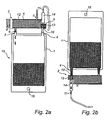
- Fig 2a is a schematic cross-section drawing of a transfusion unit according to the invention, as seen in a collection position.
- Fig 2b is a schematic cross-section drawing of the inventive transfusion unit in fig 2a , as seen in a retransfusion position.
- Fig 3 is a schematic cross-section drawing of a detail of the inventive transfusion unit as disclosed in fig 2a .
- Fig 2a, fig 2b and fig 3 discloses a first embodiment of this invention.
- a transfusion unit 16 is disclosed in a first, collection position.
- Fig 2b shows the transfusion unit 16 in a retransfusion position.
- the transfusion unit 16 essentially comprises a body fluid bag 1, such as a bag for collecting blood or plasma, the bag 1 being manufactured from a flexible material, such as a plastic material.
- the body fluid bag 1 is a blood bag, for collection of blood.
- the transfusion unit 16 also comprises an integrated filtering device 2, which will be described in closer detail below.
- the integrated filtering device 2 is essentially subdivided into a filtering part 5 and a retransfusion part 6, said parts being integrated into a single mechanical component, which is connected to the blood bag 1.
- the filtering part 5 of the filtering device 2 essentially comprises a filtering part inlet opening 7, which may be connected to a source of blood, for example a patient or a donor, a filter 12, and a filtering part outlet 8, which is connected to a bag inlet opening 3 on said blood bag 1.
- the filter 12 is a mechanical filter, which may or may not be coated with an active substance, such as antibodies, in order to allow filtration of leukocytes, lipids and undesired proteins.
- the filter material and structure may be chosen to suit the desired purpose.
- the filter may be folded one or more times within the filtering part 5, in order to increase the filtering area of the filter.
- a check valve 9 is provided between the filtering part outlet 8 and the bag inlet opening 3, the check valve 9 serving to allow flow only from the filtering part 5 to the blood bag 1.
- the retransfusion part 6 of the filtering device 2 essentially comprises a retransfusion part inlet opening 10, which is connected to a blood bag outlet opening 4 of said blood bag 1, a retransfusion drip chamber 14 and a retransfusion part outlet opening 11, which is arranged to be connected to a recipient of the retransfused blood, such as a patient or a collecting device or the like.
- the retransfusion part 6 may also comprise an additional retransfusion filter 13, being arranged upstream said retransfusion drip chamber. This retransfusion filter 13 may be used to filter out for example blood clots which may arise when storing blood collected in said blood bag 1.
- a flow channel such as a tube, is connected between said blood source and said inlet opening 7 of said filtering part 5.
- the transfusion unit When blood is to be collected, the transfusion unit is in the position disclosed in fig 2a . Blood is thereafter drained from said blood source and is transferred to the transfusion device, via said filtering part inlet opening 7, by means of pressure (Means for generating said pressure is not disclosed in the present drawings). Alternatively, a pump may be used to transfer blood into the transfusion unit 16, via said filtering part inlet opening 7. By means of gravity, the blood is thereafter transported through the filter 12 of the filtering part 5 of the filtering device 2, whereby particles present in the blood, such as thrombi, tissue fragments or the like is filtered away.
- the filter in which the filter is coated with an active substance, such as antibodies, also blood components such as leukocytes, lipids, undesired proteins and other inflammatory chemical mediators of cytokines, may be filtered away.
- an active substance such as antibodies
- blood components such as leukocytes, lipids, undesired proteins and other inflammatory chemical mediators of cytokines
- the transfusion unit 16 When the blood stored in the blood bag is to be used, for example retransfused into a patient, which may or may not be the same as the donor or blood source, the transfusion unit 16 is placed so that blood can pass through the retransfusion part 6 and the drips in the drip chamber fall vertically, as indicated by fig 2b .
- a suspension opening 15 is provided in the blood bag.
- the transfusion unit 16 When the transfusion unit 16 is turned upside down, the content of the blood bag 1 is forced by means of gravity into the bag inlet and outlet openings 3, 4. A flow of blood out through the bag inlet opening 3 is prohibited by the provision of said check valve 9, which prohibits flow in that direction. Instead, the flow of blood is directed out through the bag outlet opening 4, connected with the retransfusion part inlet opening 10.
- the blood is passed through the retransfusion filter 13, which filters out any blood clots or the like which have been generated during storage of blood in the blood bag 1. Thereafter, the filtered blood is passed to the retransfusion drip chamber 14, whereafter the blood is allowed to exit the transfusion unit 16 through said retransfusion part outlet opening 11.
- the retransfusion part outlet opening 11 is suitably connected to a tube, which in its other end is connected to a cannula in a patient. On this tube, means for throttling the flow of blood to the patient are provided in order to provide a desired velocity of flow of blood to the patient.
- the filtering device 2 and the blood bag 1 are connected to each other by means of two connections, one constituted by the filtering part outlet opening 8 and the bag inlet opening 3, and the other one constituted by the bag outlet opening 4 and the retransfusion part inlet opening 10.
- the invention is not to be limited to this arrangement.
- the main issue is that the connection between the filtering device 2 and the blood bag 1 provides for a first flow of blood between the filtering part and the blood bag when the bag is in the collection position disclosed in fig 2a , and a second flow of blood between the blood bag and the retransfusion part 6 when the bag is in the retransfusion position disclosed in fig 2b .
- the position of the check valve 9 is not of main importance for this invention.
- the check valve 9 may for example be positioned within the filtering part 5, in connection with said filtering part outlet opening 8, or in the blood bag 1, in connection with said blood bag inlet opening 3.
- the check valve 9 may be realised as a separate component, to be used as a connection part, when connecting the filtering part outlet opening 8 with the bag inlet opening 3.
- a clamp or a regular valve may be provided in the same position, in order to obtain the same function, but manually operated.
- the filtering part 5 and the retransfusion part 6 are only mechanically connected and integrated into a single unit constituting said filtering device 2.
- This mechanical integration is advantageous in that it facilitates manufacturing and simple assembly.
- the transfusion unit is delivered in a state where the bag 1 is connected with the filtering device 2. This also results in easy handling, and the entire unit may be sterilised at once.
- the filtering part comprises a housing, into which said filtering part inlet and outlet openings are emanating, and a filter being arranged in said housing, whereby said inlet and outlet openings are arranged at essentially opposite sides of said housing in order to provide a sufficiently long flow path for said body fluid through the filter in said housing.
- the housing is suitably manufactured from a plastic material, which may be sterilised. Such a housing is also suitable for automatic manufacture.
- the bag used with the present invention may be of standard type, and may be provided in a cost-efficient manner.
- inventive solution may be used for collection and retransfusion of other body fluids, besides blood, such as plasma.
- the present invention also may be used in an alternative manner, in which the transfusion unit constantly is in the position disclosed in fig 2b .
- the body fluid is forced into the bag, via said filter, by means of pressure, and a clamp, a valve or the like may be used to regulate the flow of body fluid out of the transfusion unit.
- the retransfusion part inlet opening 10 is directly connected with a further filtering part outlet opening, which further filtering part outlet opening is arranged downstream the filter in the filtering part and situated adjacent the retransfusion part inlet opening 10.
- the purpose with this construction is to avoid that body fluid remains in the filtering part adjacent the retransfusion part when the body fluid bag is positioned with the filtering part outlet opening on a higher level than the retransfusion part inlet opening 10.
- the body fluid bag has a common inlet and outlet opening to which the filtering part outlet opening and the retransfusion part inlet opening are directly connected.
- a body fluid bag is intended to cover a fluid bag of a flexible plastic material and also a fluid bag of stiff material.
Landscapes
- Health & Medical Sciences (AREA)
- Heart & Thoracic Surgery (AREA)
- Vascular Medicine (AREA)
- Life Sciences & Earth Sciences (AREA)
- Engineering & Computer Science (AREA)
- Anesthesiology (AREA)
- Biomedical Technology (AREA)
- Hematology (AREA)
- Cardiology (AREA)
- Animal Behavior & Ethology (AREA)
- General Health & Medical Sciences (AREA)
- Public Health (AREA)
- Veterinary Medicine (AREA)
- External Artificial Organs (AREA)
- Medical Preparation Storing Or Oral Administration Devices (AREA)
- Infusion, Injection, And Reservoir Apparatuses (AREA)
Abstract
Description
- This invention relates to a device for a body fluid bag, the device comprising a filtering part and a transfusion part. The invention also relates to a transfusion unit, comprising such a device.
- During for example surgery, such as chest cavity surgery, a patient usually loses large amounts of blood. One way of dealing with this problem is to remove the lost blood and give the patient a transfusion of donated blood, to make up for the lost blood. Such donations are however accompanied with a plurality of problems, such as rejection of the donated blood, and the risk for spreading diseases.
- In order to overcome these problems, it has been proposed in the prior art to collect blood lost from the patient and return this blood to the circulatory system of the patient. This is referred to as autologous blood transfusion. A transfusion unit according to the prior art is disclosed in
fig 1a and 1b . This transfusion unit comprises a blood bag, which has an inlet in an upper part of the bag and an outlet in the lower part of the bag. Within the blood bag, a main filter is integrated, so that blood that is entered into the blood bag is filtered. This filtration is essential in autologous blood transfusion, since it removes impurities, such as thrombi and tissue fragments in a wound. After filtration, the blood is collected in the bottom of the blood bag until it is to be retransfused. In this collection position (fig 1a ), the outlet from the bag is blocked by means of a clamp or the like. When the blood is to be retransfused (fig 1b ), a transfusion set is connected to the outlet of the bag. Thereafter the clamp is removed, and the transfusion set filter is primed and all air is expelled from the tubing before the transfusion set being connected to a cannula or the like in the patient and blood is retransfused into the patient. The transfusion set may be equipped with a blood filter in order to remove any blood clots or the like which may develop when storing the blood in the blood bag. - However, the prior art device described above have a plurality of disadvantages. First, the main filter is integrated in the blood bag, which means that only special blood bags may be used for this purpose. Moreover, these blood bags are quite complicated, and hence quite costly to manufacture. Moreover, as the blood bag is filled with blood, there is a risk that the level of blood may rise so that the stored blood is in contact with the filter while stored, which may decrease the quality of the stored blood.
- Hence, an object of this invention is to overcome the above mentioned problems with the prior art.
- The above and other objects are at least in part achieved with a device as claimed in claim 1. According to this claim, a device for a body fluid bag is provided, the device comprising a filtering part and a retransfusion part, the filtering part having a filtering part inlet opening and a filtering part outlet opening, the outlet opening being arranged to be connected to an inlet opening of said body fluid bag, and the retransfusion part having a retransfusion part inlet opening, being arranged to be connected to an outlet opening of said body fluid bag, and an retransfusion part outlet opening, wherein said filtering part and said retransfusion part are mechanically integrated to form a single unit. Hence, according to the invention, regular blood bags, which may be manufactured at low cost, may be used for autologous blood transfusion. Moreover, since the filtering part is separated from the blood bag, there is no risk for the filter affecting the blood quality, when the blood has entered the blood bag. Also, the inventive solution is flexible, and blood bags of different materials, sizes and designs may be used.
- Suitably, the device further comprises a check valve arranged in proximity with the filtering part outlet opening, in order to allow a flow of filtered body fluid in the direction from the filtering part to the fluid bag and to hinder a flow in the opposite direction. This prevents that blood is re-entered into the filter once it has entered the blood bag from the filter.
Moreover, said retransfusion part comprises an integrated drip chamber, in order to control a flow of body fluid out from said retransfusion part outlet opening. Suitably, said retransfusion part also comprises a retransfusion filter, arranged up-stream said drip chamber, for filtering for example blood clots that may arise in the blood bag. - Suitably, the filtering part comprises a housing, into which said filtering part inlet and outlet openings are emanating, and a filter being arranged in said housing, whereby said inlet and outlet openings are arranged at essentially opposite sides of said housing in order to provide a sufficiently long flow path for said body fluid through the filter in said housing, enabling good filtration of the body fluid.
- The above and other objects of the invention are also at least in part achieved by a transfusion unit comprising a body fluid bag, having a bag inlet opening and a bag outlet opening, and a device as defined above, having a filtering part outlet opening and a retransfusion part inlet opening, said filtering part outlet opening being connected to the bag inlet opening and the retransfusion part inlet opening being connected to the bag outlet opening. By the inventive arrangement, a unit is provided that is simple to use and may be manufactured cost-efficiently. The inventive arrangement also provides for a solution in which the parts needed for retransfusion is included in the device, and the unit may be sterilised as a unit, resulting in a hygienic solution. Suitably, said body fluid bag is a flexible bag, for example a bag of a plastic material.
- The invention will hereinafter be described in closer detail by means of preferred embodiments thereof, with reference to the accompanying drawings.
-
Fig 1a is a schematic cross-section drawing of a transfusion unit according to the prior art, as seen in a collection position. -
Fig I b is a schematic cross-section drawing of the transfusion unit infig 1a , as seen in a retransfusion position. -
Fig 2a is a schematic cross-section drawing of a transfusion unit according to the invention, as seen in a collection position. -
Fig 2b is a schematic cross-section drawing of the inventive transfusion unit infig 2a , as seen in a retransfusion position. -
Fig 3 is a schematic cross-section drawing of a detail of the inventive transfusion unit as disclosed infig 2a . -
Fig 2a, fig 2b andfig 3 discloses a first embodiment of this invention. With reference tofig 2a andfig 3 , atransfusion unit 16 is disclosed in a first, collection position.Fig 2b shows thetransfusion unit 16 in a retransfusion position. Thetransfusion unit 16 essentially comprises a body fluid bag 1, such as a bag for collecting blood or plasma, the bag 1 being manufactured from a flexible material, such as a plastic material. In the present example, the body fluid bag 1 is a blood bag, for collection of blood. Thetransfusion unit 16 also comprises an integratedfiltering device 2, which will be described in closer detail below. - The integrated
filtering device 2 is essentially subdivided into a filteringpart 5 and aretransfusion part 6, said parts being integrated into a single mechanical component, which is connected to the blood bag 1. - The filtering
part 5 of thefiltering device 2 essentially comprises a filtering part inlet opening 7, which may be connected to a source of blood, for example a patient or a donor, afilter 12, and a filteringpart outlet 8, which is connected to a bag inlet opening 3 on said blood bag 1. Thefilter 12 is a mechanical filter, which may or may not be coated with an active substance, such as antibodies, in order to allow filtration of leukocytes, lipids and undesired proteins. Moreover, the filter material and structure may be chosen to suit the desired purpose. As is indicated infig 2a , the filter may be folded one or more times within the filteringpart 5, in order to increase the filtering area of the filter. Furthermore, acheck valve 9 is provided between the filteringpart outlet 8 and the bag inlet opening 3, thecheck valve 9 serving to allow flow only from the filteringpart 5 to the blood bag 1. - The
retransfusion part 6 of thefiltering device 2 essentially comprises a retransfusionpart inlet opening 10, which is connected to a blood bag outlet opening 4 of said blood bag 1, aretransfusion drip chamber 14 and a retransfusion part outlet opening 11, which is arranged to be connected to a recipient of the retransfused blood, such as a patient or a collecting device or the like. Theretransfusion part 6 may also comprise anadditional retransfusion filter 13, being arranged upstream said retransfusion drip chamber. Thisretransfusion filter 13 may be used to filter out for example blood clots which may arise when storing blood collected in said blood bag 1. - The function of the above described
transfusion unit 16 will hereinafter be described. - When blood is to be collected from a blood source, a flow channel, such as a tube, is connected between said blood source and said inlet opening 7 of said filtering
part 5. When blood is to be collected, the transfusion unit is in the position disclosed infig 2a . Blood is thereafter drained from said blood source and is transferred to the transfusion device, via said filtering part inlet opening 7, by means of pressure (Means for generating said pressure is not disclosed in the present drawings). Alternatively, a pump may be used to transfer blood into thetransfusion unit 16, via said filtering part inlet opening 7. By means of gravity, the blood is thereafter transported through thefilter 12 of thefiltering part 5 of thefiltering device 2, whereby particles present in the blood, such as thrombi, tissue fragments or the like is filtered away. According to an embodiment of the invention described above, in which the filter is coated with an active substance, such as antibodies, also blood components such as leukocytes, lipids, undesired proteins and other inflammatory chemical mediators of cytokines, may be filtered away. Once filtered, the blood flows through the filteringpart outlet opening 8, thecheck valve 9 and thebag inlet opening 3, into the blood bag 1, in which the blood may be stored until it is to be used. - When the blood stored in the blood bag is to be used, for example retransfused into a patient, which may or may not be the same as the donor or blood source, the
transfusion unit 16 is placed so that blood can pass through theretransfusion part 6 and the drips in the drip chamber fall vertically, as indicated byfig 2b . For this purpose, asuspension opening 15 is provided in the blood bag. When thetransfusion unit 16 is turned upside down, the content of the blood bag 1 is forced by means of gravity into the bag inlet andoutlet openings bag inlet opening 3 is prohibited by the provision of saidcheck valve 9, which prohibits flow in that direction. Instead, the flow of blood is directed out through thebag outlet opening 4, connected with the retransfusionpart inlet opening 10. First, the blood is passed through theretransfusion filter 13, which filters out any blood clots or the like which have been generated during storage of blood in the blood bag 1. Thereafter, the filtered blood is passed to theretransfusion drip chamber 14, whereafter the blood is allowed to exit thetransfusion unit 16 through said retransfusionpart outlet opening 11. The retransfusionpart outlet opening 11 is suitably connected to a tube, which in its other end is connected to a cannula in a patient. On this tube, means for throttling the flow of blood to the patient are provided in order to provide a desired velocity of flow of blood to the patient. - As indicated above, in the present example, the
filtering device 2 and the blood bag 1 are connected to each other by means of two connections, one constituted by the filteringpart outlet opening 8 and thebag inlet opening 3, and the other one constituted by thebag outlet opening 4 and the retransfusionpart inlet opening 10. However, it shall be noted that the invention is not to be limited to this arrangement. The main issue is that the connection between thefiltering device 2 and the blood bag 1 provides for a first flow of blood between the filtering part and the blood bag when the bag is in the collection position disclosed infig 2a , and a second flow of blood between the blood bag and theretransfusion part 6 when the bag is in the retransfusion position disclosed infig 2b . This may however be realised with a single connection between thefiltering part 2, and the blood bag 1, in which case internal flow distribution channels may be provided in thefiltering device 2. The above function may also be realised with multiple connections between thefiltering device 2 and the blood bag 1. In any case, saidcheck valve 9 is arranged to prevent flow of blood into thefiltering part 5, when thetransfusion unit 16 is in the retransfusion position disclosed infig 2b . In the case of multiple connections,multiple check valves 9 may be used to realise this function. - Also, it shall be noted that the position of the
check valve 9 is not of main importance for this invention. Thecheck valve 9 may for example be positioned within thefiltering part 5, in connection with said filteringpart outlet opening 8, or in the blood bag 1, in connection with said bloodbag inlet opening 3. Alternative, thecheck valve 9 may be realised as a separate component, to be used as a connection part, when connecting the filteringpart outlet opening 8 with thebag inlet opening 3. Also, it shall be noted that instead of saidcheck valve 9, a clamp or a regular valve may be provided in the same position, in order to obtain the same function, but manually operated. - In the shown embodiment there is no fluid connection between the
filtering part 5 and theretransfusion part 6, but they are only mechanically connected and integrated into a single unit constituting saidfiltering device 2. This mechanical integration is advantageous in that it facilitates manufacturing and simple assembly. Moreover, in most cases the transfusion unit is delivered in a state where the bag 1 is connected with thefiltering device 2. This also results in easy handling, and the entire unit may be sterilised at once. - Essentially, the filtering part comprises a housing, into which said filtering part inlet and outlet openings are emanating, and a filter being arranged in said housing, whereby said inlet and outlet openings are arranged at essentially opposite sides of said housing in order to provide a sufficiently long flow path for said body fluid through the filter in said housing. The provision of said housing makes it easy to exchange the filter, and to easily manufacture transfusion units having different filter types. The housing is suitably manufactured from a plastic material, which may be sterilised. Such a housing is also suitable for automatic manufacture. Moreover, the bag used with the present invention may be of standard type, and may be provided in a cost-efficient manner.
- The above description of preferred embodiments of the invention is only given by way of example, and the invention is only to be limited to what is stated in the following claims. As an example, the inventive solution may be used for collection and retransfusion of other body fluids, besides blood, such as plasma.
- It shall also be noted that the present invention also may be used in an alternative manner, in which the transfusion unit constantly is in the position disclosed in
fig 2b . In that case, the body fluid is forced into the bag, via said filter, by means of pressure, and a clamp, a valve or the like may be used to regulate the flow of body fluid out of the transfusion unit. - In the shown embodiment there is no fluid connection between the
filtering part 5 and theretransfusion part 6. In an alternative embodiment the retransfusion part inlet opening 10 is directly connected with a further filtering part outlet opening, which further filtering part outlet opening is arranged downstream the filter in the filtering part and situated adjacent the retransfusionpart inlet opening 10. The purpose with this construction is to avoid that body fluid remains in the filtering part adjacent the retransfusion part when the body fluid bag is positioned with the filtering part outlet opening on a higher level than the retransfusionpart inlet opening 10. In a further alternative embodiment the body fluid bag has a common inlet and outlet opening to which the filtering part outlet opening and the retransfusion part inlet opening are directly connected. - The used expression a body fluid bag is intended to cover a fluid bag of a flexible plastic material and also a fluid bag of stiff material.
Claims (7)
- A device (2) for a body fluid bag, the device comprising a filtering part (5) and a retransfusion part (6),
the filtering part (5) having a filtering part inlet opening (7) and a filtering part outlet opening (8), the outlet opening (8) being arranged to be connected to an inlet opening of said body fluid bag,
and the retransfusion part (6) having a retransfusion part inlet opening (10), being arranged to be connected to an outlet opening of said body fluid bag, and an retransfusion part outlet opening (11),
wherein said filtering part (5) and said retransfusion part (6) are mechanically integrated to form a single unit. - A device as in claim 1, further comprising a check valve (9) arranged in proximity with the filtering part outlet opening (8), in order to allow a flow of filtered body fluid in the direction from the filtering part (5) to the fluid bag and to hinder a flow in the opposite direction.
- A device as in claim 1 or 2, wherein said retransfusion part (6) comprises an integrated drip chamber (14), in order to control a flow of body fluid out from said retransfusion part outlet opening (11).
- A device as in claim 3, wherein said retransfusion part (6) comprises a retransfusion filter (13), arranged up-stream said drip chamber (14).
- A device as claimed in any of the preceding claims, wherein the filtering part (5) comprises a housing, into which said filtering part inlet and outlet openings (7, 8) are emanating, and a filter (12) being arranged in said housing, whereby said inlet and outlet openings (7, 8) are arranged at essentially opposite sides of said housing in order to provide a sufficiently long flow path for said body fluid through the filter in said housing.
- A transfusion unit comprising a body fluid bag (1), having a bag inlet opening
(3) and a bag outlet opening (4), and a device (2) as defined in any one of the claims 1-5, having a filtering part outlet opening (8) and a retransfusion part inlet opening (10), said filtering part outlet opening (8) being connected to the bag inlet opening (3) and the retransfusion part inlet opening (10) being connected to the bag outlet opening (4). - A transfusion unit according to claim 6, wherein said body fluid bag (1) is a flexible bag, for example a bag of a plastic material.
Applications Claiming Priority (3)
| Application Number | Priority Date | Filing Date | Title |
|---|---|---|---|
| SE0300855 | 2003-03-26 | ||
| SE0300855A SE525177C2 (en) | 2003-03-26 | 2003-03-26 | Apparatus for a body fluid bag comprising a filtration member and a retransfusion member mechanically connected to a single unit, and a transfusion unit |
| PCT/SE2004/000448 WO2004084792A1 (en) | 2003-03-26 | 2004-03-24 | Device for a body fluid bag |
Publications (2)
| Publication Number | Publication Date |
|---|---|
| EP1605889A1 EP1605889A1 (en) | 2005-12-21 |
| EP1605889B1 true EP1605889B1 (en) | 2009-05-06 |
Family
ID=20290808
Family Applications (1)
| Application Number | Title | Priority Date | Filing Date |
|---|---|---|---|
| EP04723125A Expired - Lifetime EP1605889B1 (en) | 2003-03-26 | 2004-03-24 | Device for a body fluid bag |
Country Status (6)
| Country | Link |
|---|---|
| US (1) | US7429325B2 (en) |
| EP (1) | EP1605889B1 (en) |
| AT (1) | ATE430546T1 (en) |
| DE (1) | DE602004020980D1 (en) |
| SE (1) | SE525177C2 (en) |
| WO (1) | WO2004084792A1 (en) |
Families Citing this family (11)
| Publication number | Priority date | Publication date | Assignee | Title |
|---|---|---|---|---|
| EP2957264A1 (en) | 2007-04-09 | 2015-12-23 | Covidien LP | Stretchable stent and delivery system |
| ITMO20070189A1 (en) * | 2007-06-01 | 2008-12-02 | Rand Srl | MEDICAL APPARATUS |
| US20170136158A1 (en) | 2015-10-16 | 2017-05-18 | Angiodynamics, Inc. | Systems and Methods for Removing Undesirable Material Within a Circulatory System |
| US10517617B2 (en) | 2007-12-20 | 2019-12-31 | Angiodynamics, Inc. | Systems and methods for removing undesirable material within a circulatory system utilizing a balloon catheter |
| US11589880B2 (en) | 2007-12-20 | 2023-02-28 | Angiodynamics, Inc. | System and methods for removing undesirable material within a circulatory system utilizing during a surgical procedure |
| CN102405070B (en) * | 2009-04-23 | 2016-01-20 | 费森尼斯医疗德国公司 | For the treatment of the device of medical fluid, external functional device and treatment facility |
| US8216409B2 (en) * | 2009-12-10 | 2012-07-10 | General Electric Company | Methods for making a housingless hollow fiber filtration apparatus |
| US12245788B2 (en) | 2011-03-15 | 2025-03-11 | Angiodynamics, Inc. | Device and method for removing material from a hollow anatomical structure |
| US9055964B2 (en) | 2011-03-15 | 2015-06-16 | Angio Dynamics, Inc. | Device and method for removing material from a hollow anatomical structure |
| DE102014014725A1 (en) * | 2014-10-02 | 2016-04-07 | Resuscitec Gmbh | Device with a bag-shaped container and method for gas bubble-free filling of a pump-driven, hollow-line-supported liquid circuit by means of the device |
| USD1107903S1 (en) * | 2023-12-27 | 2025-12-30 | B. Braun Medical Inc. | Flexible container for mixing and administering drugs and feeds |
Family Cites Families (13)
| Publication number | Priority date | Publication date | Assignee | Title |
|---|---|---|---|---|
| US2848995A (en) * | 1949-07-06 | 1958-08-26 | Abbott Lab | Transfusion apparatus |
| US3492991A (en) * | 1967-02-23 | 1970-02-03 | Richard H Dyer Jr | Autotransfusion apparatus |
| US4033345A (en) * | 1975-11-13 | 1977-07-05 | Sorenson Research Co., Inc. | Autologous transfusion filter system and method |
| ATE16350T1 (en) * | 1980-05-20 | 1985-11-15 | Haemonetics Corp | LIQUID SUCTION APPARATUS AND FLEXIBLE LIQUID COLLECTING BAG SUITED FOR USE IN SUCH APPARATUS. |
| US4435170A (en) * | 1981-06-15 | 1984-03-06 | Solco Basel Ag | Assembly for receiving and discharging a collection of blood |
| US5133703A (en) * | 1986-02-18 | 1992-07-28 | Boehringer Laboratories | Process and apparatus for collecting blood of a patient for autotransfusion |
| US4834743A (en) * | 1986-11-10 | 1989-05-30 | Sherwood Medical Company | Autologous transfusion system and apparatus |
| US5695489A (en) * | 1991-09-30 | 1997-12-09 | Baxter International Inc. | Blood filtering container |
| US5445731A (en) * | 1993-09-08 | 1995-08-29 | Texaco Inc. | Pervaporation vessel |
| EP1049495A2 (en) * | 1998-01-23 | 2000-11-08 | Pall Corporation | Biological fluid treatment system |
| US6099734A (en) * | 1998-07-08 | 2000-08-08 | Baxter International Inc. | Apparatus, membranes and methods for removing organic compounds from a biological fluid |
| NL1016515C2 (en) * | 2000-10-31 | 2002-05-07 | Straten Beheer B V Van | Wound drainage and retransfusion device, has retransfusion hose, filter, dosing device and closure device stored in space beneath collection vessel |
| DE10152105A1 (en) * | 2001-10-23 | 2003-05-08 | Fresenius Medical Care De Gmbh | Container for use in dialysis |
-
2003
- 2003-03-26 SE SE0300855A patent/SE525177C2/en not_active IP Right Cessation
-
2004
- 2004-03-24 WO PCT/SE2004/000448 patent/WO2004084792A1/en not_active Ceased
- 2004-03-24 AT AT04723125T patent/ATE430546T1/en not_active IP Right Cessation
- 2004-03-24 US US10/548,670 patent/US7429325B2/en not_active Expired - Fee Related
- 2004-03-24 DE DE602004020980T patent/DE602004020980D1/en not_active Expired - Fee Related
- 2004-03-24 EP EP04723125A patent/EP1605889B1/en not_active Expired - Lifetime
Also Published As
| Publication number | Publication date |
|---|---|
| SE525177C2 (en) | 2004-12-14 |
| SE0300855D0 (en) | 2003-03-26 |
| US7429325B2 (en) | 2008-09-30 |
| US20060191830A1 (en) | 2006-08-31 |
| SE0300855L (en) | 2004-09-27 |
| WO2004084792A1 (en) | 2004-10-07 |
| ATE430546T1 (en) | 2009-05-15 |
| EP1605889A1 (en) | 2005-12-21 |
| DE602004020980D1 (en) | 2009-06-18 |
Similar Documents
| Publication | Publication Date | Title |
|---|---|---|
| CN108136110B (en) | Filters with gradient porosity | |
| US5871693A (en) | Modular blood treatment cartridge | |
| US5798041A (en) | In-line liquid filtration device useable for blood, blood products or the like | |
| CA1044103A (en) | Cardiotomy reservoir | |
| US7429325B2 (en) | Device for a body fluid bag | |
| JP5559216B2 (en) | Apparatus and method for processing blood | |
| EP0190020A2 (en) | Unitary venous return reservoir with cardiotomy filter | |
| US4747952A (en) | Method and apparatus for plasma treatment | |
| EP1626757B1 (en) | Method of continuous blood filtration | |
| US20110268608A1 (en) | Oxygenator with integrated arterial filter | |
| EA016521B1 (en) | A high capacity biological fluid filtration apparatus | |
| US20030057147A1 (en) | Filtration device and system for biological fluids | |
| EP4114480B1 (en) | A hybrid venous reservoir | |
| EP2383001B1 (en) | Oxygenator with integrated arterial filter | |
| EP2160213B1 (en) | Kit for the extracorporeal treatment of a biological fluid of a patient, and unit provided with said kit | |
| WO2008146132A2 (en) | Medical apparatus | |
| JP4297767B2 (en) | Blood processing filter system | |
| CN111148538B (en) | Blood filtration device | |
| JPS64940Y2 (en) |
Legal Events
| Date | Code | Title | Description |
|---|---|---|---|
| PUAI | Public reference made under article 153(3) epc to a published international application that has entered the european phase |
Free format text: ORIGINAL CODE: 0009012 |
|
| 17P | Request for examination filed |
Effective date: 20050909 |
|
| AK | Designated contracting states |
Kind code of ref document: A1 Designated state(s): AT BE BG CH CY CZ DE DK EE ES FI FR GB GR HU IE IT LI LU MC NL PL PT RO SE SI SK TR |
|
| AX | Request for extension of the european patent |
Extension state: AL LT LV MK |
|
| DAX | Request for extension of the european patent (deleted) | ||
| 17Q | First examination report despatched |
Effective date: 20061212 |
|
| GRAP | Despatch of communication of intention to grant a patent |
Free format text: ORIGINAL CODE: EPIDOSNIGR1 |
|
| GRAS | Grant fee paid |
Free format text: ORIGINAL CODE: EPIDOSNIGR3 |
|
| GRAA | (expected) grant |
Free format text: ORIGINAL CODE: 0009210 |
|
| AK | Designated contracting states |
Kind code of ref document: B1 Designated state(s): AT BE BG CH CY CZ DE DK EE ES FI FR GB GR HU IE IT LI LU MC NL PL PT RO SE SI SK TR |
|
| REG | Reference to a national code |
Ref country code: GB Ref legal event code: FG4D |
|
| REG | Reference to a national code |
Ref country code: CH Ref legal event code: EP |
|
| REG | Reference to a national code |
Ref country code: IE Ref legal event code: FG4D |
|
| REF | Corresponds to: |
Ref document number: 602004020980 Country of ref document: DE Date of ref document: 20090618 Kind code of ref document: P |
|
| PG25 | Lapsed in a contracting state [announced via postgrant information from national office to epo] |
Ref country code: FI Free format text: LAPSE BECAUSE OF FAILURE TO SUBMIT A TRANSLATION OF THE DESCRIPTION OR TO PAY THE FEE WITHIN THE PRESCRIBED TIME-LIMIT Effective date: 20090506 Ref country code: AT Free format text: LAPSE BECAUSE OF FAILURE TO SUBMIT A TRANSLATION OF THE DESCRIPTION OR TO PAY THE FEE WITHIN THE PRESCRIBED TIME-LIMIT Effective date: 20090506 Ref country code: ES Free format text: LAPSE BECAUSE OF FAILURE TO SUBMIT A TRANSLATION OF THE DESCRIPTION OR TO PAY THE FEE WITHIN THE PRESCRIBED TIME-LIMIT Effective date: 20090817 Ref country code: PT Free format text: LAPSE BECAUSE OF FAILURE TO SUBMIT A TRANSLATION OF THE DESCRIPTION OR TO PAY THE FEE WITHIN THE PRESCRIBED TIME-LIMIT Effective date: 20090906 |
|
| NLV1 | Nl: lapsed or annulled due to failure to fulfill the requirements of art. 29p and 29m of the patents act | ||
| PG25 | Lapsed in a contracting state [announced via postgrant information from national office to epo] |
Ref country code: SI Free format text: LAPSE BECAUSE OF FAILURE TO SUBMIT A TRANSLATION OF THE DESCRIPTION OR TO PAY THE FEE WITHIN THE PRESCRIBED TIME-LIMIT Effective date: 20090506 Ref country code: PL Free format text: LAPSE BECAUSE OF FAILURE TO SUBMIT A TRANSLATION OF THE DESCRIPTION OR TO PAY THE FEE WITHIN THE PRESCRIBED TIME-LIMIT Effective date: 20090506 Ref country code: NL Free format text: LAPSE BECAUSE OF FAILURE TO SUBMIT A TRANSLATION OF THE DESCRIPTION OR TO PAY THE FEE WITHIN THE PRESCRIBED TIME-LIMIT Effective date: 20090506 Ref country code: SE Free format text: LAPSE BECAUSE OF FAILURE TO SUBMIT A TRANSLATION OF THE DESCRIPTION OR TO PAY THE FEE WITHIN THE PRESCRIBED TIME-LIMIT Effective date: 20090806 |
|
| PG25 | Lapsed in a contracting state [announced via postgrant information from national office to epo] |
Ref country code: CZ Free format text: LAPSE BECAUSE OF FAILURE TO SUBMIT A TRANSLATION OF THE DESCRIPTION OR TO PAY THE FEE WITHIN THE PRESCRIBED TIME-LIMIT Effective date: 20090506 Ref country code: DK Free format text: LAPSE BECAUSE OF FAILURE TO SUBMIT A TRANSLATION OF THE DESCRIPTION OR TO PAY THE FEE WITHIN THE PRESCRIBED TIME-LIMIT Effective date: 20090506 Ref country code: EE Free format text: LAPSE BECAUSE OF FAILURE TO SUBMIT A TRANSLATION OF THE DESCRIPTION OR TO PAY THE FEE WITHIN THE PRESCRIBED TIME-LIMIT Effective date: 20090506 Ref country code: RO Free format text: LAPSE BECAUSE OF FAILURE TO SUBMIT A TRANSLATION OF THE DESCRIPTION OR TO PAY THE FEE WITHIN THE PRESCRIBED TIME-LIMIT Effective date: 20090506 |
|
| PG25 | Lapsed in a contracting state [announced via postgrant information from national office to epo] |
Ref country code: SK Free format text: LAPSE BECAUSE OF FAILURE TO SUBMIT A TRANSLATION OF THE DESCRIPTION OR TO PAY THE FEE WITHIN THE PRESCRIBED TIME-LIMIT Effective date: 20090506 Ref country code: BE Free format text: LAPSE BECAUSE OF FAILURE TO SUBMIT A TRANSLATION OF THE DESCRIPTION OR TO PAY THE FEE WITHIN THE PRESCRIBED TIME-LIMIT Effective date: 20090506 |
|
| PLBE | No opposition filed within time limit |
Free format text: ORIGINAL CODE: 0009261 |
|
| STAA | Information on the status of an ep patent application or granted ep patent |
Free format text: STATUS: NO OPPOSITION FILED WITHIN TIME LIMIT |
|
| PG25 | Lapsed in a contracting state [announced via postgrant information from national office to epo] |
Ref country code: BG Free format text: LAPSE BECAUSE OF FAILURE TO SUBMIT A TRANSLATION OF THE DESCRIPTION OR TO PAY THE FEE WITHIN THE PRESCRIBED TIME-LIMIT Effective date: 20090806 |
|
| 26N | No opposition filed |
Effective date: 20100209 |
|
| PGFP | Annual fee paid to national office [announced via postgrant information from national office to epo] |
Ref country code: GB Payment date: 20100302 Year of fee payment: 7 |
|
| PGFP | Annual fee paid to national office [announced via postgrant information from national office to epo] |
Ref country code: FR Payment date: 20100416 Year of fee payment: 7 |
|
| PG25 | Lapsed in a contracting state [announced via postgrant information from national office to epo] |
Ref country code: GR Free format text: LAPSE BECAUSE OF FAILURE TO SUBMIT A TRANSLATION OF THE DESCRIPTION OR TO PAY THE FEE WITHIN THE PRESCRIBED TIME-LIMIT Effective date: 20090807 Ref country code: MC Free format text: LAPSE BECAUSE OF NON-PAYMENT OF DUE FEES Effective date: 20100331 |
|
| REG | Reference to a national code |
Ref country code: CH Ref legal event code: PL |
|
| PG25 | Lapsed in a contracting state [announced via postgrant information from national office to epo] |
Ref country code: IE Free format text: LAPSE BECAUSE OF NON-PAYMENT OF DUE FEES Effective date: 20100324 |
|
| PG25 | Lapsed in a contracting state [announced via postgrant information from national office to epo] |
Ref country code: LI Free format text: LAPSE BECAUSE OF NON-PAYMENT OF DUE FEES Effective date: 20100331 Ref country code: DE Free format text: LAPSE BECAUSE OF NON-PAYMENT OF DUE FEES Effective date: 20101001 Ref country code: CH Free format text: LAPSE BECAUSE OF NON-PAYMENT OF DUE FEES Effective date: 20100331 |
|
| PG25 | Lapsed in a contracting state [announced via postgrant information from national office to epo] |
Ref country code: IT Free format text: LAPSE BECAUSE OF FAILURE TO SUBMIT A TRANSLATION OF THE DESCRIPTION OR TO PAY THE FEE WITHIN THE PRESCRIBED TIME-LIMIT Effective date: 20090506 |
|
| GBPC | Gb: european patent ceased through non-payment of renewal fee |
Effective date: 20110324 |
|
| REG | Reference to a national code |
Ref country code: FR Ref legal event code: ST Effective date: 20111130 |
|
| PG25 | Lapsed in a contracting state [announced via postgrant information from national office to epo] |
Ref country code: FR Free format text: LAPSE BECAUSE OF NON-PAYMENT OF DUE FEES Effective date: 20110331 |
|
| PG25 | Lapsed in a contracting state [announced via postgrant information from national office to epo] |
Ref country code: GB Free format text: LAPSE BECAUSE OF NON-PAYMENT OF DUE FEES Effective date: 20110324 |
|
| PG25 | Lapsed in a contracting state [announced via postgrant information from national office to epo] |
Ref country code: CY Free format text: LAPSE BECAUSE OF FAILURE TO SUBMIT A TRANSLATION OF THE DESCRIPTION OR TO PAY THE FEE WITHIN THE PRESCRIBED TIME-LIMIT Effective date: 20090506 |
|
| PG25 | Lapsed in a contracting state [announced via postgrant information from national office to epo] |
Ref country code: HU Free format text: LAPSE BECAUSE OF FAILURE TO SUBMIT A TRANSLATION OF THE DESCRIPTION OR TO PAY THE FEE WITHIN THE PRESCRIBED TIME-LIMIT Effective date: 20091107 Ref country code: LU Free format text: LAPSE BECAUSE OF NON-PAYMENT OF DUE FEES Effective date: 20100324 |
|
| PG25 | Lapsed in a contracting state [announced via postgrant information from national office to epo] |
Ref country code: TR Free format text: LAPSE BECAUSE OF FAILURE TO SUBMIT A TRANSLATION OF THE DESCRIPTION OR TO PAY THE FEE WITHIN THE PRESCRIBED TIME-LIMIT Effective date: 20090506 |