EP1605690B1 - Housing for CCTV camera - Google Patents
Housing for CCTV camera Download PDFInfo
- Publication number
- EP1605690B1 EP1605690B1 EP05253504.4A EP05253504A EP1605690B1 EP 1605690 B1 EP1605690 B1 EP 1605690B1 EP 05253504 A EP05253504 A EP 05253504A EP 1605690 B1 EP1605690 B1 EP 1605690B1
- Authority
- EP
- European Patent Office
- Prior art keywords
- housing
- camera
- slot
- case
- slots
- Prior art date
- Legal status (The legal status is an assumption and is not a legal conclusion. Google has not performed a legal analysis and makes no representation as to the accuracy of the status listed.)
- Ceased
Links
Images



Classifications
-
- H—ELECTRICITY
- H04—ELECTRIC COMMUNICATION TECHNIQUE
- H04N—PICTORIAL COMMUNICATION, e.g. TELEVISION
- H04N7/00—Television systems
- H04N7/18—Closed-circuit television [CCTV] systems, i.e. systems in which the video signal is not broadcast
-
- G—PHYSICS
- G08—SIGNALLING
- G08B—SIGNALLING SYSTEMS, e.g. PERSONAL CALLING SYSTEMS; ORDER TELEGRAPHS; ALARM SYSTEMS
- G08B13/00—Burglar, theft or intruder alarms
- G08B13/18—Actuation by interference with heat, light, or radiation of shorter wavelength; Actuation by intruding sources of heat, light, or radiation of shorter wavelength
- G08B13/189—Actuation by interference with heat, light, or radiation of shorter wavelength; Actuation by intruding sources of heat, light, or radiation of shorter wavelength using passive radiation detection systems
- G08B13/194—Actuation by interference with heat, light, or radiation of shorter wavelength; Actuation by intruding sources of heat, light, or radiation of shorter wavelength using passive radiation detection systems using image scanning and comparing systems
- G08B13/196—Actuation by interference with heat, light, or radiation of shorter wavelength; Actuation by intruding sources of heat, light, or radiation of shorter wavelength using passive radiation detection systems using image scanning and comparing systems using television cameras
- G08B13/19617—Surveillance camera constructional details
- G08B13/19619—Details of casing
-
- G—PHYSICS
- G08—SIGNALLING
- G08B—SIGNALLING SYSTEMS, e.g. PERSONAL CALLING SYSTEMS; ORDER TELEGRAPHS; ALARM SYSTEMS
- G08B13/00—Burglar, theft or intruder alarms
- G08B13/18—Actuation by interference with heat, light, or radiation of shorter wavelength; Actuation by intruding sources of heat, light, or radiation of shorter wavelength
- G08B13/189—Actuation by interference with heat, light, or radiation of shorter wavelength; Actuation by intruding sources of heat, light, or radiation of shorter wavelength using passive radiation detection systems
- G08B13/194—Actuation by interference with heat, light, or radiation of shorter wavelength; Actuation by intruding sources of heat, light, or radiation of shorter wavelength using passive radiation detection systems using image scanning and comparing systems
- G08B13/196—Actuation by interference with heat, light, or radiation of shorter wavelength; Actuation by intruding sources of heat, light, or radiation of shorter wavelength using passive radiation detection systems using image scanning and comparing systems using television cameras
- G08B13/19617—Surveillance camera constructional details
- G08B13/1963—Arrangements allowing camera rotation to change view, e.g. pivoting camera, pan-tilt and zoom [PTZ]
-
- H—ELECTRICITY
- H04—ELECTRIC COMMUNICATION TECHNIQUE
- H04N—PICTORIAL COMMUNICATION, e.g. TELEVISION
- H04N23/00—Cameras or camera modules comprising electronic image sensors; Control thereof
- H04N23/50—Constructional details
- H04N23/51—Housings
Definitions
- the present invention relates to a housing for a camera. More particularly, the present invention relates to a housing for a CCTV (closed-circuit television) camera which is easily opened and assembled.
- CCTV closed-circuit television
- WO03/077530 (Hage et al ) describes a quick-release sensor assembly where snap-fit elements or a slot and key arrangement are provided to couple together two housing sub-components.
- US5,940,122 (Kizawa et al ) describes a housing assembly for a surveillance camera including a covering member having projections which snap into holes in a housing member.
- a CCTV camera receives incident light from a subject in front of the camera. The light passes through a lens and is converted into an electrical signal by a CCD (charge-coupled device) or other similar device. Thus, the camera transmits an electrical signal (image data) corresponding to the subject in front of the camera.
- CCD charge-coupled device
- a CCTV camera is supplied with alternating current (AC) power and converts the AC power into direct current (DC) power for internal operating power.
- a CCTV camera generally has a driver for driving a CCD, and signal processing circuits for processing a video signal based on the image data output from the CCD.
- the signal processing circuits output the processed video signals to an external monitor or video recorder.
- CCTV cameras are used in a wide variety of environments, such as residential areas, offices, hospitals, banks, department stores, and so on, for a variety of purposes. The purposes include preventing property theft, increasing security and public safety, controlling building entry, and monitoring mechanical operations and work flow in industrial locations. Recently, CCTV cameras have been installed in other environments such as underground parking lots and other areas where crimes frequently occur.
- cameras usually use a built-in focus-adjusting pin or a zoom-adjusting pin.
- the cameras are generally mounted in an external housing to protect the camera from external impacts and other environmental changes.
- a conventional CCTV camera 1 is mounted in a housing comprising a housing front portion 3 and a housing rear portion 4.
- the housing front portion 3 and the housing rear portion 4 are securely fastened to each mechanically using fasteners such as bolts and nuts.
- a user may occasionally need to adjust the focus, the zoom, or the diaphragm of the CCTV camera 1.
- the housing front portion 3 must be opened to adjust a CCTV camera-adjusting pin 2. In fact, it may be necessary to make frequent adjustments because the ambient environment of the CCTV camera 1 changes frequently.
- An aim of the present invention is to address at least the above problems and/or disadvantages and/or to provide at least some of the advantages described below.
- An aspect of the present invention provides a housing for a CCTV camera that can be easily opened and assembled so that the CCTV camera mounted therein can be easily adjusted.
- Another aspect of the present invention provides a housing for a CCTV camera which securely fixes the camera.
- a housing for a CCTV camera includes a housing cap having a filter glass.
- the filter glass is located on the front surface of the housing cap and filters incident light from an external light source and supplies the filtered light to a CCTV camera lens.
- One or more connecting protrusions are formed on a rear end of the housing cap along a circumference having a predetermined curvature.
- a camera case has as many first slots as protrusions formed on its front surface. The case accommodates and fixes the CCTV camera.
- the housing cap is connected with the camera case such that the connecting protrusions are inserted into the first slots to then be rotated by a predetermined angle to lock the housing cap onto the housing case.
- Each of the connecting protrusions may have a predetermined height, and may include a tapered portion formed on an end of the connecting protrusion so that the connecting protrusion is easily inserted into a corresponding first slot.
- the connecting protrusion may have a flange having a predetermined height to prevent the connecting protrusion from escaping from the first slot once inserted into the first slot.
- Each of the first slots may include an opened slot, a locked slot, and a divisional protrusion.
- the opened slot has a height in a circumferential direction that is substantially the same as the maximum height of the connecting protrusion.
- the connecting protrusion is inserted into the opened slot when the housing cap is inserted into the camera case.
- the locked slot has a height in a circumferential direction that is substantially the same as the predetermined height of the connecting protrusion.
- the connecting protrusion is placed into the locked slot when the housing cap is rotated in a predetermined direction into a locked position.
- a divisional protrusion is located between the opened and locked slots. The divisional protrusion allows the position of the connecting protrusion to be changed from the opened slot to the locked slot, or from the locked slot to the opened slot, only when a predetermined amount of rotational force is applied to the housing cap.
- the camera case may further include second slots spaced a predetermined distance away from and parallel to the first slots formed on the front surface.
- the first and second slots form resilient elastic portions, which are deformed by even a small compressive force and return to their original positions when the compressive force is removed.
- the camera case may include an upper case and a lower case so that the CCTV camera can be easily installed into the camera case.
- the CCTV camera, the upper case, and the lower case can be connected together to form a single body.
- the camera case may also include a connecting-line guide slot (35), which guides a board-connecting line of the CCTV camera to a CCD board installed inside the camera case to prevent the line from being caught between the upper and lower cases.
- a connecting-line guide slot 35
- the camera case may further include a step-correcting protrusion.
- the protrusion expands the rear end of the housing cap in a predetermined direction when the housing cap is inserted into the camera case and rotated, thereby correcting a step between the rear end of the housing cap and the front surface of the camera case.
- FIG. 2 illustrates a camera housing according to an embodiment of the present invention.
- the camera housing comprises a housing cap 10 and a camera case 25.
- the housing case 25 has an elliptical shape and is divided into an upper case 20 and a lower case 30.
- the CCTV camera 40 is fixed into the camera housing.
- the camera housing is preferably formed of a lightweight, elastomeric material.
- the housing (other than the filter glass portion) may be formed of a synthetic resin such as plastic.
- the housing cap 10 is elliptical in a cross-section perpendicular to an axial direction, and includes a filter glass 11 on its front surface.
- the filter glass 11 filters incident light from an external light source and supplies the filtered light to a CCTV camera lens.
- the CCTV camera 40 comprises a camera lens 41 which receives light from a light source, a focus-adjusting pin 42 which adjusts the focus of the camera, a zoom-adjusting pin 43 which adjusts the degree of zoom, a camera flange 44 which allows the CCTV camera 40 to be fit into the front surface of the camera case 25 to prevent the CCTV camera 40 from escaping from the camera case 25, camera fixing locks 45a and 45b which allow the CCTV camera 40 to be engaged with the camera case 25, and a board-connecting line 46 which connects the camera 40 to a CCD board (not shown).
- the upper case 20 may include a predetermined number of first slots 36b and 36c, as many second slots 37b and 37c as first slots 36b and 36c, a step-correcting protrusion 34a, and an upper accommodating-hole 38a which accommodates the CCTV camera 40.
- the lower case 30 may include a predetermined number of first slots 36a and 36d, as many second slots 37a and 37d as first slots 36a and 36d, a step-correcting protrusion 34b, a lower accommodating-hole 38b which accommodates the CCTV camera 40, screw bosses 32a and 32b to receive screws passing through the camera fixing locks 45a and 45b, a screw boss 31 for connecting the upper case 20 and the lower case 30 together, and a connecting line guide slot 35 which guides the board-connecting line 46 so that it is not caught between the upper case 20 and the lower case 30 but is instead connected to the CCD board.
- Figure 3 illustrates the camera case 25 when the upper case 20 is connected to the lower case 30.
- the camera case When connected, the camera case has two step-correcting protrusions 34a and 34b, four first slots 36a-d, four second slots 37a-d, an accommodating hole 38, and a connecting-line guide groove 35 on the front surface of the camera case 25.
- At least one throughhole (not shown) through which a connecting line (not shown) passes is provided on a rear surface of the camera case 25.
- a CCD board or a PCB board may be connected to a power source and an external device, such as a video encoder, or any other suitable device, by the connecting line.
- Figure 4 illustrates the combination of a CCTV camera 40, a CCD board 60, and a PCB board 50.
- this combination will be referred to as a combined camera-circuit body.
- the CCTV camera 40 is connected to the CCD board 60 by a connecting line 46 to pass analog signals generated by the CCTV camera in response to captured light to the CCD board.
- the CCD board 60 is connected to the PCB board 50 by a connecting line 55 to transmit and receive data.
- the CCD board 60 and the PCB board 50 are preferably fixedly installed in the camera case 25. That is, the CCD board 60 is fixed inside the camera case 25, and the PCB board 50 is fixed inside the upper case 20 of the camera case 25.
- the CCD board 60 includes a predetermined number of throughholes 61a and 61b through which the CCD board 60 is connected to a front surface of the camera case 25 by mechanical fasteners such as a bolts and nuts.
- the PCB board 50 includes a predetermined number of throughholes 51a, 51b, 51c, and 51d to allow the PCB board 50 to be connected to the upper case 20 by mechanical fasteners such as bolts and nuts.
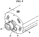
- FIG 5 illustrates the combined camera-circuit body shown in Figure 4 installed inside the camera case 25.
- the board connecting line 46 has moved to a peripheral part (39b of Figure 3 ) of the connecting line guide slot 35 from a starting part (39a of Figure 3 ) of the connecting-line guide slot 35.
- the connecting line guide slot 35 has a hook shape that allows the board connecting line 46 to moves to the peripheral part 39b.
- the CCTV camera 40 and the CCD board 60 are installed inside the camera case 25 after the board connecting line 46 of the CCTV camera 40 has been connected to the CCD board 60.
- one end of the connecting-line guide slot 35 is open to the accommodating hole 38 to allow the connecting line 46 to be placed into the guide slot.
- the housing cap 10 is not installed on the camera case 25. With the housing cap 10 removed, a user can adjust operating conditions of the CCTV camera 40 by adjusting the focus adjusting pin 42 or the zoom adjusting pin 43.
- Figure 6 illustrates the connection between the housing cap 10 and the camera case 25.
- Connecting protrusions 13a, 13b, 13c, and 13d are formed at a rear end of the housing cap 10 along a circumference having a predetermined curvature and are connected with first slots 36a, 36b, 36c, and 36d of the camera case 25.
- the number of the connecting protrusions 13a, 13b, 13c, and 13d is the same as the number of the first slots 36a, 36b, 36c, and 36d of the camera case 25.
- the first slots 36a, 36b, 36c, and 36d formed on the front surface of the camera case 25 are formed along a circumference having the same predetermined curvature as the connecting protrusions.
- each of the connecting protrusions 13a-d and each of the slots 36a-d has substantially the same structure. Thus, for conciseness, only the construction and operation of the set of connecting protrusion 13c and slot 36c will be described in detail. The description is, of course, equally applicable to the other sets of connecting protrusions and slots.
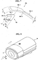
- FIG. 7 is a detailed diagram of the connecting protrusion 13c and the first slot 36c.
- the connecting protrusion 13c has a tapered portion 13c-1 formed on an end so that the connecting protrusion 13c is easily inserted into the first slot 36c.
- the connecting protrusion 13c also has a flange 13c-2 that prevents the connecting protrusion 13c from escaping from the first slot 36c once inserted into the first slot 36c.
- the flange 13c-2 has a height corresponding to a difference between a maximum height t3 of the connecting protrusion 13c and a predetermined height t4 of the connecting protrusion 13c.
- the first slot 36c has an opened slot 36c-1, a locked slot 36c-2, and a divisional protrusion 36c-3.
- the opened slot 36c-1 has a height t1 in a circumferential direction, and the height t1 is substantially the same as the maximum height t3 of the connecting protrusion 13c.
- the connecting protrusion 13c of the housing cap 10 is inserted into the first slot 36c.
- the locked slot 36c-2 has a height t2 in a circumferential direction, and the height t2 is substantially the same as the predetermined height t4 of the connecting protrusion 13c.
- the width of the locked slot 36c-2 is substantially the same as the width w of the connecting protrusion 13c.
- the connecting protrusion 13c is placed in the locked slot 36c-2 when the housing cap 10 is rotated clockwise.
- the divisional protrusion 36c-3 allows the position of the connecting protrusion 13c to be changed from the opened slot 36c-1 to the locked slot 36c-2 or from the locked slot 36c-2 to the opened slot 36c-1 only when a predetermined rotating force is applied to the housing cap 10.
- the divisional protrusion 36c-3 allows the user to detect by sound or by feel that the position of the connecting protrusion 13c has been changed.
- FIG 8 illustrates a process of connecting the housing cap 10 with the camera case 25.
- the housing cap 10 is pushed into a front surface of the camera case 25 in an axial direction as indicated by the arrow "B.”
- the connecting protrusions (13a, 13b, 13c, and 13d shown in Figure 6 ) of the housing cap 10 are inserted into the corresponding opened slots (36a-1, 36b-1, 36c-1, and 36d-1 as shown in Figure 7 ) of the first slots (36a, 36b, 36c, and 36d shown in Figure 2 ) of the camera case 25.
- the housing cap 10 is rotated clockwise by a predetermined angle as indicated by the arrow "C.”
- the predetermined angle varies according to the width of the first slots 36a, 36b, 36c, and 36d, and is preferably 20 degrees.
- the above-described process is reversed.
- the housing cap 10 is rotated counterclockwise by a predetermined angle and then pulled in the axial direction, thereby disconnecting the housing cap 10 from the camera case 25.
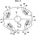
- Figure 9 is a cross-sectional view taken along line A-A' of Figure 8 .
- the connecting protrusions 13a, 13b, 13c, and 13d are placed inside the camera case 25 and are not allowed to escape from the camera case 25 by the flanges 13a-2, 13b-2, 13c-2, and 13d-2 (as shown in Figure 7 ).
- Second slots 37a, 37b, 37c, and 37d which are spaced a predetermined distance away from and parallel to the first slots 36a, 36b, 36c, and 36d, are formed on the front surface of the camera case 25.
- Resilient, elastic portions 33a, 33b, 33c, and 33d which are deformed by even a small compressive force and return to their original positions when the compressive force is removed, are formed between each of the first slots 36a, 36b, 36c, and 36d and each of the second slots 37a, 37b, 37c, and 37d.
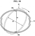
- FIG 10 is a diagram explaining the function of the step-correcting protrusion 34a.
- the step-correcting protrusion 34a expands the rear end of the housing cap 10 in a predetermined direction when the housing cap 10 is inserted into the camera case 25 and rotated, thereby correcting a step between the rear end of the housing cap 10 and the front surface of the camera case 25.
- the external side of the rear end of the housing cap 10 and the external side of the front surface of the camera case 25 should mate smoothly without any step.
- the rear end of the housing cap 10 is open and it can be easily deformed by heat or pressure.
- the internal height h2 of the housing cap may shrink. If the deformed housing cap is mounted to the camera case 25, there will be a step at the junction of the housing cap 10 and the camera case 25.
- step-correcting protrusions 34a and 34b are provided on the front surface of the camera case 25.
- the internal height of the rear end of the housing cap 10 is h2.
- the internal height of the rear end of the housing cap 10 is enlarged to h1 by the step-correcting protrusions 34a and 34b, thereby preventing a step between the housing cap 10 and the camera case 25.
- the housing and the CCTV camera can be easily assembled to and disassembled from each other.
- a user can easily perform fine adjustment of the CCTV camera.
- a user can easily clean the lens and filter glass located on the front portion of the housing of the CCTV camera.
Landscapes
- Physics & Mathematics (AREA)
- General Physics & Mathematics (AREA)
- Engineering & Computer Science (AREA)
- Multimedia (AREA)
- Signal Processing (AREA)
- Studio Devices (AREA)
- Blocking Light For Cameras (AREA)
Description
- The present invention relates to a housing for a camera. More particularly, the present invention relates to a housing for a CCTV (closed-circuit television) camera which is easily opened and assembled.
-
US2004/042,779 (Maeda et al ) describes a lens housing detachably mounted to a camera housing using a bayonet engagement with claws entering an opening and rotated into an engagement portion. -
WO03/077530 (Hage et al -
US5,940,122 (Kizawa et al ) describes a housing assembly for a surveillance camera including a covering member having projections which snap into holes in a housing member. - Various kinds of cameras are known, such as ordinary cameras, CCTV cameras, and so on. In general, a CCTV camera receives incident light from a subject in front of the camera. The light passes through a lens and is converted into an electrical signal by a CCD (charge-coupled device) or other similar device. Thus, the camera transmits an electrical signal (image data) corresponding to the subject in front of the camera.
- Generally, a CCTV camera is supplied with alternating current (AC) power and converts the AC power into direct current (DC) power for internal operating power. A CCTV camera generally has a driver for driving a CCD, and signal processing circuits for processing a video signal based on the image data output from the CCD. The signal processing circuits output the processed video signals to an external monitor or video recorder. CCTV cameras are used in a wide variety of environments, such as residential areas, offices, hospitals, banks, department stores, and so on, for a variety of purposes. The purposes include preventing property theft, increasing security and public safety, controlling building entry, and monitoring mechanical operations and work flow in industrial locations. Recently, CCTV cameras have been installed in other environments such as underground parking lots and other areas where crimes frequently occur.
- In such environments, cameras usually use a built-in focus-adjusting pin or a zoom-adjusting pin. The cameras are generally mounted in an external housing to protect the camera from external impacts and other environmental changes.
- Referring to
Figure 1 , aconventional CCTV camera 1 is mounted in a housing comprising ahousing front portion 3 and a housingrear portion 4. Thehousing front portion 3 and the housingrear portion 4 are securely fastened to each mechanically using fasteners such as bolts and nuts. - A user may occasionally need to adjust the focus, the zoom, or the diaphragm of the
CCTV camera 1. To make the adjustments, thehousing front portion 3 must be opened to adjust a CCTV camera-adjustingpin 2. In fact, it may be necessary to make frequent adjustments because the ambient environment of theCCTV camera 1 changes frequently. - It is quite troublesome and inconvenient to open the
housing front portion 3, which is securely fastened to the housingrear portion 4, every time adjustment is necessary. - There is a need for a housing for a CCTV camera that can be easily opened to make adjustments.
- According to the present invention there is provided an apparatus and method as set forth in the appended claims. Preferred features of the invention will be apparent from the dependent claims, and the description which follows.
- An aim of the present invention is to address at least the above problems and/or disadvantages and/or to provide at least some of the advantages described below.
- An aspect of the present invention provides a housing for a CCTV camera that can be easily opened and assembled so that the CCTV camera mounted therein can be easily adjusted.
- Another aspect of the present invention provides a housing for a CCTV camera which securely fixes the camera.
- In accordance with an aspect of the present invention, a housing for a CCTV camera includes a housing cap having a filter glass. The filter glass is located on the front surface of the housing cap and filters incident light from an external light source and supplies the filtered light to a CCTV camera lens. One or more connecting protrusions are formed on a rear end of the housing cap along a circumference having a predetermined curvature. A camera case has as many first slots as protrusions formed on its front surface. The case accommodates and fixes the CCTV camera. The housing cap is connected with the camera case such that the connecting protrusions are inserted into the first slots to then be rotated by a predetermined angle to lock the housing cap onto the housing case.
- Each of the connecting protrusions may have a predetermined height, and may include a tapered portion formed on an end of the connecting protrusion so that the connecting protrusion is easily inserted into a corresponding first slot. The connecting protrusion may have a flange having a predetermined height to prevent the connecting protrusion from escaping from the first slot once inserted into the first slot.
- Each of the first slots may include an opened slot, a locked slot, and a divisional protrusion. The opened slot has a height in a circumferential direction that is substantially the same as the maximum height of the connecting protrusion. The connecting protrusion is inserted into the opened slot when the housing cap is inserted into the camera case. The locked slot has a height in a circumferential direction that is substantially the same as the predetermined height of the connecting protrusion. The connecting protrusion is placed into the locked slot when the housing cap is rotated in a predetermined direction into a locked position. A divisional protrusion is located between the opened and locked slots. The divisional protrusion allows the position of the connecting protrusion to be changed from the opened slot to the locked slot, or from the locked slot to the opened slot, only when a predetermined amount of rotational force is applied to the housing cap.
- The camera case may further include second slots spaced a predetermined distance away from and parallel to the first slots formed on the front surface. The first and second slots form resilient elastic portions, which are deformed by even a small compressive force and return to their original positions when the compressive force is removed.
- The camera case may include an upper case and a lower case so that the CCTV camera can be easily installed into the camera case. The CCTV camera, the upper case, and the lower case can be connected together to form a single body.
- The camera case may also include a connecting-line guide slot (35), which guides a board-connecting line of the CCTV camera to a CCD board installed inside the camera case to prevent the line from being caught between the upper and lower cases.
- The camera case may further include a step-correcting protrusion. The protrusion expands the rear end of the housing cap in a predetermined direction when the housing cap is inserted into the camera case and rotated, thereby correcting a step between the rear end of the housing cap and the front surface of the camera case.
- The above and other objects, features, and advantages of certain embodiments of the present invention will be more apparent from the following description taken in conjunction with the accompanying drawings, in which:
-
Figure 1 is a perspective view of a conventional CCTV camera; -
Figure 2 is an exploded perspective view of a camera housing in accordance with an embodiment of the present invention; -
Figure 3 is a perspective of the camera case shown inFigure 2 ; -
Figure 4 is a perspective view of a combined camera-circuit body of the camera housing shown inFigure 2 ; -
Figure 5 is a perspective view showing the combined camera-circuit body shown inFigure 4 installed inside the camera case shown inFigure 3 ; -
Figure 6 is an exploded perspective view illustrating the connection between the housing cap and the camera case in accordance with an embodiment of the present invention; -
Figure 7 is a detailed diagram of a connecting protrusion and a first slot in accordance with an embodiment of the present invention; -
Figure 8 illustrates a process of connecting the housing cap and the camera case with each other in accordance with an embodiment of the present invention; -
Figure 9 is a cross-sectional view taken along line A-A' ofFigure 8 ; and -
Figure 10 is a diagram that illustrates the function of a step-correcting protrusion in accordance with an embodiment of the present invention. - Throughout the drawings, the same drawing reference numerals will be understood to refer to the same elements, features, and structures.
- The matters defined in the description such as a detailed construction and elements are provided to assist in a comprehensive understanding of the embodiments of the invention. Accordingly, those of ordinary skill in the art will recognize that various changes and modifications of the embodiments described herein can be made without departing from the scope and spirit of the invention. Also, descriptions of well-known functions and constructions are omitted for clarity and conciseness.
-
Figure 2 illustrates a camera housing according to an embodiment of the present invention. The camera housing comprises ahousing cap 10 and acamera case 25. Thehousing case 25 has an elliptical shape and is divided into anupper case 20 and alower case 30. When theupper case 20 and thelower case 30 are connected with each other, theCCTV camera 40 is fixed into the camera housing. The camera housing is preferably formed of a lightweight, elastomeric material. Specifically, the housing (other than the filter glass portion) may be formed of a synthetic resin such as plastic. - The
housing cap 10 is elliptical in a cross-section perpendicular to an axial direction, and includes afilter glass 11 on its front surface. Thefilter glass 11 filters incident light from an external light source and supplies the filtered light to a CCTV camera lens. - The
CCTV camera 40 comprises acamera lens 41 which receives light from a light source, a focus-adjustingpin 42 which adjusts the focus of the camera, a zoom-adjustingpin 43 which adjusts the degree of zoom, acamera flange 44 which allows theCCTV camera 40 to be fit into the front surface of thecamera case 25 to prevent theCCTV camera 40 from escaping from thecamera case 25,camera fixing locks 45a and 45b which allow theCCTV camera 40 to be engaged with thecamera case 25, and a board-connectingline 46 which connects thecamera 40 to a CCD board (not shown). - The
upper case 20 may include a predetermined number offirst slots second slots first slots protrusion 34a, and an upper accommodating-hole 38a which accommodates theCCTV camera 40. - The
lower case 30 may include a predetermined number offirst slots second slots first slots protrusion 34b, a lower accommodating-hole 38b which accommodates theCCTV camera 40,screw bosses camera fixing locks 45a and 45b, ascrew boss 31 for connecting theupper case 20 and thelower case 30 together, and a connectingline guide slot 35 which guides the board-connectingline 46 so that it is not caught between theupper case 20 and thelower case 30 but is instead connected to the CCD board. -
Figure 3 illustrates thecamera case 25 when theupper case 20 is connected to thelower case 30. When connected, the camera case has two step-correctingprotrusions first slots 36a-d, foursecond slots 37a-d, anaccommodating hole 38, and a connecting-line guide groove 35 on the front surface of thecamera case 25. At least one throughhole (not shown) through which a connecting line (not shown) passes is provided on a rear surface of thecamera case 25. A CCD board or a PCB board may be connected to a power source and an external device, such as a video encoder, or any other suitable device, by the connecting line. -
Figure 4 illustrates the combination of aCCTV camera 40, aCCD board 60, and aPCB board 50. For convenience, this combination will be referred to as a combined camera-circuit body. As seen inFigure 4 , theCCTV camera 40 is connected to theCCD board 60 by a connectingline 46 to pass analog signals generated by the CCTV camera in response to captured light to the CCD board. TheCCD board 60, in turn, is connected to thePCB board 50 by a connectingline 55 to transmit and receive data. - The
CCD board 60 and thePCB board 50 are preferably fixedly installed in thecamera case 25. That is, theCCD board 60 is fixed inside thecamera case 25, and thePCB board 50 is fixed inside theupper case 20 of thecamera case 25. To this end, theCCD board 60 includes a predetermined number ofthroughholes CCD board 60 is connected to a front surface of thecamera case 25 by mechanical fasteners such as a bolts and nuts. Simililarly, thePCB board 50 includes a predetermined number ofthroughholes PCB board 50 to be connected to theupper case 20 by mechanical fasteners such as bolts and nuts. -
Figure 5 illustrates the combined camera-circuit body shown inFigure 4 installed inside thecamera case 25. Here, theboard connecting line 46 has moved to a peripheral part (39b ofFigure 3 ) of the connectingline guide slot 35 from a starting part (39a ofFigure 3 ) of the connecting-line guide slot 35. The connectingline guide slot 35 has a hook shape that allows theboard connecting line 46 to moves to theperipheral part 39b. Typically, theCCTV camera 40 and theCCD board 60 are installed inside thecamera case 25 after theboard connecting line 46 of theCCTV camera 40 has been connected to theCCD board 60. Thus, during installation of the connected pieces, one end of the connecting-line guide slot 35 is open to theaccommodating hole 38 to allow the connectingline 46 to be placed into the guide slot. - In
Figure 5 , thehousing cap 10 is not installed on thecamera case 25. With thehousing cap 10 removed, a user can adjust operating conditions of theCCTV camera 40 by adjusting thefocus adjusting pin 42 or thezoom adjusting pin 43. -
Figure 6 illustrates the connection between thehousing cap 10 and thecamera case 25. Connectingprotrusions housing cap 10 along a circumference having a predetermined curvature and are connected withfirst slots camera case 25. The number of the connectingprotrusions first slots camera case 25. Thefirst slots camera case 25 are formed along a circumference having the same predetermined curvature as the connecting protrusions. - Each of the connecting
protrusions 13a-d and each of theslots 36a-d has substantially the same structure. Thus, for conciseness, only the construction and operation of the set of connectingprotrusion 13c andslot 36c will be described in detail. The description is, of course, equally applicable to the other sets of connecting protrusions and slots. -
Figure 7 is a detailed diagram of the connectingprotrusion 13c and thefirst slot 36c. The connectingprotrusion 13c has a taperedportion 13c-1 formed on an end so that the connectingprotrusion 13c is easily inserted into thefirst slot 36c. The connectingprotrusion 13c also has aflange 13c-2 that prevents the connectingprotrusion 13c from escaping from thefirst slot 36c once inserted into thefirst slot 36c. Theflange 13c-2 has a height corresponding to a difference between a maximum height t3 of the connectingprotrusion 13c and a predetermined height t4 of the connectingprotrusion 13c. - The
first slot 36c has an openedslot 36c-1, a lockedslot 36c-2, and adivisional protrusion 36c-3. The openedslot 36c-1 has a height t1 in a circumferential direction, and the height t1 is substantially the same as the maximum height t3 of the connectingprotrusion 13c. The connectingprotrusion 13c of thehousing cap 10 is inserted into thefirst slot 36c. The lockedslot 36c-2 has a height t2 in a circumferential direction, and the height t2 is substantially the same as the predetermined height t4 of the connectingprotrusion 13c. The width of the lockedslot 36c-2 is substantially the same as the width w of the connectingprotrusion 13c. The connectingprotrusion 13c is placed in the lockedslot 36c-2 when thehousing cap 10 is rotated clockwise. Thedivisional protrusion 36c-3 allows the position of the connectingprotrusion 13c to be changed from the openedslot 36c-1 to the lockedslot 36c-2 or from the lockedslot 36c-2 to the openedslot 36c-1 only when a predetermined rotating force is applied to thehousing cap 10. In addition, thedivisional protrusion 36c-3 allows the user to detect by sound or by feel that the position of the connectingprotrusion 13c has been changed. -
Figure 8 illustrates a process of connecting thehousing cap 10 with thecamera case 25. First, thehousing cap 10 is pushed into a front surface of thecamera case 25 in an axial direction as indicated by the arrow "B." Here, the connecting protrusions (13a, 13b, 13c, and 13d shown inFigure 6 ) of thehousing cap 10 are inserted into the corresponding opened slots (36a-1, 36b-1, 36c-1, and 36d-1 as shown inFigure 7 ) of the first slots (36a, 36b, 36c, and 36d shown inFigure 2 ) of thecamera case 25. Next, thehousing cap 10 is rotated clockwise by a predetermined angle as indicated by the arrow "C." The predetermined angle varies according to the width of thefirst slots - To disassemble the
housing cap 10 from thecamera case 25, the above-described process is reversed. In other words, thehousing cap 10 is rotated counterclockwise by a predetermined angle and then pulled in the axial direction, thereby disconnecting thehousing cap 10 from thecamera case 25. -
Figure 9 is a cross-sectional view taken along line A-A' ofFigure 8 . After thehousing cap 10 is inserted into thecamera case 25 and rotated, the connectingprotrusions camera case 25 and are not allowed to escape from thecamera case 25 by theflanges 13a-2, 13b-2, 13c-2, and 13d-2 (as shown inFigure 7 ). - When the connecting
protrusions slots 36a-1, 36b-1, 36c-1, and 36d-1 and each of the lockedslots 36a-2, 36b-2, 36c-2, and 36d-2 (as shown inFigure 7 ), a compressive force is applied to thedivisional protrusions 36a-3, 36b-3, 36c-3, and 36d-3 (as shown inFigure 7 ), so that the user can detect the change from an opened state to a closed state. Accordingly, thedivisional protrusions 36a-3, 36b-3, 36c-3, and 36d-3 (as shown inFigure 7 ) should have some elasticity.Second slots first slots camera case 25. Resilient,elastic portions first slots second slots second slots protrusions slots 36a-1, 36b-1, 36c-1, and 36d-1 (as shown inFigure 7 ) and each of the lockedslots 36a-2, 36b-2, 36c-2, and 36d-2 (as shown inFigure 7 ). Further, thedivisional protrusions 36a-3, 36b-3, 36c-3, and 36d-3 (as shown inFigure 7 ) may be abraded, preventing thedivisional protrusions 36a-3, 36b-3, 36c-3, and 36d-3 (as shown inFigure 7 ) from functioning properly. -
Figure 10 is a diagram explaining the function of the step-correctingprotrusion 34a. The step-correctingprotrusion 34a expands the rear end of thehousing cap 10 in a predetermined direction when thehousing cap 10 is inserted into thecamera case 25 and rotated, thereby correcting a step between the rear end of thehousing cap 10 and the front surface of thecamera case 25. To explain further, referring back toFigure 8 , when thehousing cap 10 and thecamera case 25 are connected with each other, the external side of the rear end of thehousing cap 10 and the external side of the front surface of thecamera case 25 should mate smoothly without any step. However, the rear end of thehousing cap 10 is open and it can be easily deformed by heat or pressure. Thus, referring toFigure 10 , the internal height h2 of the housing cap may shrink. If the deformed housing cap is mounted to thecamera case 25, there will be a step at the junction of thehousing cap 10 and thecamera case 25. - To correct this step, step-correcting
protrusions camera case 25. As shown inFigure 10 , when thehousing cap 10 is placed at a position indicated by the dotted line, that is, when thehousing cap 10 is initially inserted into thecamera case 25, the internal height of the rear end of thehousing cap 10 is h2. After thehousing cap 10 is rotated and fixed, the internal height of the rear end of thehousing cap 10 is enlarged to h1 by the step-correctingprotrusions housing cap 10 and thecamera case 25. - As described above, in a housing for the CCTV camera according to the present invention, the housing and the CCTV camera can be easily assembled to and disassembled from each other. Thus, a user can easily perform fine adjustment of the CCTV camera. Further, a user can easily clean the lens and filter glass located on the front portion of the housing of the CCTV camera.
- Although a few preferred embodiments have been shown and described, it will be appreciated by those skilled in the art that various changes and modifications might be made without departing from the scope of the invention, as defined in the appended claims.
Claims (10)
- A housing for a CCTV camera, the housing comprising:a housing cap (10) having a filter glass (11) which filters incident light from an external light source and supplies the filtered light to a CCTV camera lens (41) on its front surface, and one or more connecting protrusions (13a-d) formed on a rear end thereof along a circumference having a predetermined curvature; anda camera case (25) having as many first slots (36a-d) as connecting protrusions (13a-d) formed on its front surface and accommodating and fixing the CCTV camera,wherein the housing cap (10) is connected with the camera case (25) such that the connecting protrusions (13a-d) are insertable into the first slots (36a-d) to then be rotateable at a predetermined angle; and
characterized in that:the camera case (25) further comprises a step-correcting protrusion (34a,b), which allows a rear end of the housing cap (10) to expand in a predetermined direction when the housing cap (10) is inserted onto the camera case (25) and rotated, thereby correcting a step between the rear end of the housing cap (10) and the front surface of the camera case (25). - The housing of claim 1, wherein a cross-section perpendicular to an axial direction of the housing cap (10) and a cross-section perpendicular to the axial direction of the camera case (25) have elliptical shapes.
- The housing of claim 1 or 2, wherein each of the connecting protrusions (13a-d) comprises:a tapered portion (13c-1) formed on an end of the connecting protrusion (13c) so that the connecting protrusion (13c) is easily inserted into a first corresponding slot (36c); anda flange (13c-2) to prevent the connecting protrusion (13c) from escaping from the first slot (36c) once inserted into the first slot (36c) and rotated.
- The housing of claim 3, wherein the flange (13c-2) has a height corresponding to a difference between a maximum height of the connecting protrusion (13c) and a height of the connecting protrusion (13c).
- The housing of any preceding claim, wherein the connecting slots are formed on the front end of the camera case (25) along a circumference having a predetermined curvature.
- The housing of any preceding claim, wherein each of the first slots (36a-d) comprises:an opened slot (36c-1), which has a height in a circumferential direction, the height being substantially the same as the maximum height of the connecting protrusion (13c), and into which the connecting protrusion (13c) is inserted when the housing cap (10) is inserted into the camera case (25);a locked slot (36c-2), which has a height in a circumferential direction, the height being substantially the same as the height of the connecting protrusion (13c), and into which the connecting protrusion (13c) is placed when the housing cap (10) is rotated in a predetermined direction; anda divisional protrusion (36c-3), which allows the position of the connecting protrusion (13c) to be changed from the opened slot (36c-1) to the locked slot (36c-2) or from the locked slot (36c-2) to the opened slot (36c-1) only when a predetermined rotating force is applied to the housing cap (10).
- The housing of claim 6, wherein the camera case (25) further comprises second slots (37a-d), which are spaced a predetermined distance apart from and parallel to the first slots (36a-d), formed on its front surface, so that resilient elastic portions are formed between each of the first slots (36a-d) and each of the second slots (37a-d).
- The housing of any preceding claim, wherein the camera case (25) includes an upper case (20) and a lower case (30) to accommodate the CCTV camera (40) in the camera case (25), and the CCTV camera (40), the upper case (20), and the lower case (30) are connected together into a single body.
- The housing of claim 8, wherein the camera case (25) further comprises a connecting-line guide slot (35), which guides a board-connecting line (46) of the CCTV camera to a CCD board (60) installed inside the camera case (25) without being caught between the upper and lower cases.
- The housing of claim 9, wherein the connecting-line guide slot (35) has a hook shape, and a peripheral part of the hook-shaped connecting-line guide slot (35) allows the board-connecting line (46) to be stably placed therein.
Applications Claiming Priority (2)
| Application Number | Priority Date | Filing Date | Title |
|---|---|---|---|
| KR2004041883 | 2004-06-08 | ||
| KR1020040041883A KR100621585B1 (en) | 2004-06-08 | 2004-06-08 | Housing for CCTV camera |
Publications (3)
| Publication Number | Publication Date |
|---|---|
| EP1605690A2 EP1605690A2 (en) | 2005-12-14 |
| EP1605690A3 EP1605690A3 (en) | 2009-11-04 |
| EP1605690B1 true EP1605690B1 (en) | 2016-08-24 |
Family
ID=34981260
Family Applications (1)
| Application Number | Title | Priority Date | Filing Date |
|---|---|---|---|
| EP05253504.4A Ceased EP1605690B1 (en) | 2004-06-08 | 2005-06-08 | Housing for CCTV camera |
Country Status (3)
| Country | Link |
|---|---|
| US (1) | US7557859B2 (en) |
| EP (1) | EP1605690B1 (en) |
| KR (1) | KR100621585B1 (en) |
Families Citing this family (20)
| Publication number | Priority date | Publication date | Assignee | Title |
|---|---|---|---|---|
| US7599000B2 (en) * | 2006-01-17 | 2009-10-06 | Lai Simon Y K | Supporting frame for CCTV camera enclosure |
| KR100750733B1 (en) * | 2006-03-27 | 2007-08-22 | 삼성전자주식회사 | External camera and video recording device equipped with the same |
| KR100731200B1 (en) * | 2006-04-12 | 2007-06-22 | 주식회사하이트론씨스템즈 | Surveillance camera |
| USD642607S1 (en) * | 2009-10-27 | 2011-08-02 | Axis Ab | Housing for surveillance camera |
| USD643452S1 (en) * | 2010-03-04 | 2011-08-16 | Axis Ab | Housing for camera |
| KR101148907B1 (en) * | 2010-05-28 | 2012-05-29 | 현대제철 주식회사 | Apparatus for protecting camera |
| USD685862S1 (en) | 2011-07-21 | 2013-07-09 | Mattel, Inc. | Toy vehicle housing |
| USD681742S1 (en) | 2011-07-21 | 2013-05-07 | Mattel, Inc. | Toy vehicle |
| USD672382S1 (en) * | 2011-09-06 | 2012-12-11 | March Networks Corporation | WDR megapixel camera |
| CN103581508A (en) * | 2012-07-18 | 2014-02-12 | 派尔高公司 | Video camera |
| USD716361S1 (en) | 2013-07-24 | 2014-10-28 | Sony Corporation | Lens-style camera |
| KR102244153B1 (en) * | 2013-09-13 | 2021-04-23 | 엘지이노텍 주식회사 | Camera module |
| US9182653B2 (en) * | 2013-10-02 | 2015-11-10 | Jordan Heilweil | Convertible mobile surveillance camera enclosure for selectively protecting camera dome |
| US9033597B1 (en) * | 2014-07-02 | 2015-05-19 | Dynacolor Inc. | Camera lens front cover and the monitoring camera having the same |
| KR102281422B1 (en) * | 2015-02-17 | 2021-07-26 | 에스엘 주식회사 | Apparatus for image acquisition of outside in vehicle |
| KR102281428B1 (en) * | 2015-02-17 | 2021-07-26 | 에스엘 주식회사 | Apparatus for image acquisition of outside in vehicle |
| USD780826S1 (en) * | 2015-11-30 | 2017-03-07 | SZ DJI Technology Co., Ltd. | Mount |
| CN105681634B (en) | 2016-01-21 | 2019-02-26 | 广州市诚臻电子科技有限公司 | It is a kind of video camera, long-range depending on saying system and its application |
| CA3072642A1 (en) * | 2017-09-01 | 2019-03-07 | Mtd Products Inc | Optical sensor housing |
| US10367980B1 (en) * | 2018-01-26 | 2019-07-30 | Zheng Li | Camera device integrated with light source and method for capturing images |
Family Cites Families (17)
| Publication number | Priority date | Publication date | Assignee | Title |
|---|---|---|---|---|
| JPS548097B1 (en) * | 1971-04-16 | 1979-04-12 | ||
| JPS6131321Y2 (en) | 1980-10-30 | 1986-09-11 | ||
| US4414576A (en) * | 1981-09-25 | 1983-11-08 | Vicon Industries, Inc. | Housing assembly for electrical apparatus |
| JPH05268503A (en) * | 1992-03-23 | 1993-10-15 | Sony Corp | Dual enclosure surveillance camera |
| JPH0698215A (en) | 1992-09-10 | 1994-04-08 | Canon Inc | Zoom lens for TV camera |
| DE4342638B4 (en) | 1992-12-25 | 2005-09-22 | Pentax Corp. | Linear guide mechanism for a zoom lens barrel |
| US5966176A (en) * | 1997-05-22 | 1999-10-12 | Zero Corporation | Camera housing |
| KR19990003406A (en) | 1997-06-25 | 1999-01-15 | 윤종용 | Memory device having multi-level cells and data writing method thereof |
| JPH11298766A (en) * | 1998-04-08 | 1999-10-29 | Matsushita Electric Ind Co Ltd | Surveillance camera |
| AU141240S (en) * | 1999-06-22 | 2000-07-25 | Axis Ab | A camera |
| JP4253941B2 (en) * | 1999-08-25 | 2009-04-15 | 株式会社富士通ゼネラル | Lens cover for surveillance camera |
| KR100709561B1 (en) * | 2000-11-20 | 2007-04-20 | 삼성전자주식회사 | Dome camera |
| US6715939B2 (en) * | 2001-07-27 | 2004-04-06 | Pelco | Universal surveillance camera holder and adaptor |
| WO2003077530A2 (en) | 2002-03-05 | 2003-09-18 | Hitron Usa | Quick-release sensor assembly and method |
| JP4085320B2 (en) * | 2002-06-24 | 2008-05-14 | 富士フイルム株式会社 | Digital camera |
| JP4017946B2 (en) * | 2002-09-02 | 2007-12-05 | 株式会社エルモ社 | Surveillance camera device |
| KR200352613Y1 (en) * | 2004-03-05 | 2004-06-07 | 황의남 | Pan-tilt dome type camera |
-
2004
- 2004-06-08 KR KR1020040041883A patent/KR100621585B1/en not_active Expired - Fee Related
-
2005
- 2005-05-31 US US11/140,076 patent/US7557859B2/en active Active
- 2005-06-08 EP EP05253504.4A patent/EP1605690B1/en not_active Ceased
Also Published As
| Publication number | Publication date |
|---|---|
| EP1605690A3 (en) | 2009-11-04 |
| EP1605690A2 (en) | 2005-12-14 |
| KR20050116849A (en) | 2005-12-13 |
| US7557859B2 (en) | 2009-07-07 |
| US20050270414A1 (en) | 2005-12-08 |
| KR100621585B1 (en) | 2006-09-08 |
Similar Documents
| Publication | Publication Date | Title |
|---|---|---|
| US7557859B2 (en) | Housing for CCTV camera | |
| US6783286B2 (en) | Monitoring camera with detachable lens housing | |
| EP2239946B1 (en) | Digital peephole viewer device | |
| US8727644B2 (en) | Camera | |
| US20040048507A1 (en) | Quick-release sensor assembly and method | |
| JP4321605B2 (en) | Lens adapter and imaging device | |
| WO2007043396A1 (en) | Dome type camera | |
| EP1452014A2 (en) | Universal security camera | |
| KR100346711B1 (en) | Projection television | |
| EP4367652B1 (en) | Video camera with alignment feature | |
| US20150103237A1 (en) | Photographing device | |
| KR100775203B1 (en) | Dome camera | |
| EP1381003B1 (en) | Surveillance camera apparatus | |
| KR100709561B1 (en) | Dome camera | |
| KR20070114573A (en) | Surveillance Camera Fixture | |
| US11445624B2 (en) | Apparatus and method for detecting disassembly of apparatus | |
| KR200277709Y1 (en) | Apparatus for dome type of surveillance camera | |
| JP2020085922A (en) | Surveillance camera and method of attaching cover of surveillance camera | |
| JP3682572B2 (en) | Doorphone slave unit with camera and intercom system with camera | |
| KR100466987B1 (en) | Focus regulation equipment of cctv camera | |
| CN109981957B (en) | Device shell and monitoring camera | |
| KR200178302Y1 (en) | Structure of equiping with lens barrel for surveillance camera | |
| KR20240145626A (en) | A sun shield for a security camera and the security camera comprising the sun shield | |
| KR100647267B1 (en) | Focusing device of surveillance camera | |
| KR101049562B1 (en) | Surveillance camera with external control switch and cable connection structure |
Legal Events
| Date | Code | Title | Description |
|---|---|---|---|
| PUAI | Public reference made under article 153(3) epc to a published international application that has entered the european phase |
Free format text: ORIGINAL CODE: 0009012 |
|
| 17P | Request for examination filed |
Effective date: 20050617 |
|
| AK | Designated contracting states |
Kind code of ref document: A2 Designated state(s): AT BE BG CH CY CZ DE DK EE ES FI FR GB GR HU IE IS IT LI LT LU MC NL PL PT RO SE SI SK TR |
|
| AX | Request for extension of the european patent |
Extension state: AL BA HR LV MK YU |
|
| PUAL | Search report despatched |
Free format text: ORIGINAL CODE: 0009013 |
|
| AK | Designated contracting states |
Kind code of ref document: A3 Designated state(s): AT BE BG CH CY CZ DE DK EE ES FI FR GB GR HU IE IS IT LI LT LU MC NL PL PT RO SE SI SK TR |
|
| AX | Request for extension of the european patent |
Extension state: AL BA HR LV MK YU |
|
| RAP1 | Party data changed (applicant data changed or rights of an application transferred) |
Owner name: SAMSUNG TECHWIN CO., LTD |
|
| AKX | Designation fees paid |
Designated state(s): GB |
|
| REG | Reference to a national code |
Ref country code: DE Ref legal event code: 8566 |
|
| 17Q | First examination report despatched |
Effective date: 20110411 |
|
| RAP1 | Party data changed (applicant data changed or rights of an application transferred) |
Owner name: HANWHA TECHWIN CO., LTD. |
|
| RAP1 | Party data changed (applicant data changed or rights of an application transferred) |
Owner name: HANWHA TECHWIN CO., LTD. |
|
| GRAP | Despatch of communication of intention to grant a patent |
Free format text: ORIGINAL CODE: EPIDOSNIGR1 |
|
| INTG | Intention to grant announced |
Effective date: 20160316 |
|
| GRAS | Grant fee paid |
Free format text: ORIGINAL CODE: EPIDOSNIGR3 |
|
| GRAA | (expected) grant |
Free format text: ORIGINAL CODE: 0009210 |
|
| AK | Designated contracting states |
Kind code of ref document: B1 Designated state(s): GB |
|
| REG | Reference to a national code |
Ref country code: GB Ref legal event code: FG4D |
|
| PLBE | No opposition filed within time limit |
Free format text: ORIGINAL CODE: 0009261 |
|
| STAA | Information on the status of an ep patent application or granted ep patent |
Free format text: STATUS: NO OPPOSITION FILED WITHIN TIME LIMIT |
|
| 26N | No opposition filed |
Effective date: 20170526 |
|
| REG | Reference to a national code |
Ref country code: GB Ref legal event code: 732E Free format text: REGISTERED BETWEEN 20191212 AND 20191218 |
|
| PGFP | Annual fee paid to national office [announced via postgrant information from national office to epo] |
Ref country code: GB Payment date: 20210524 Year of fee payment: 17 |
|
| GBPC | Gb: european patent ceased through non-payment of renewal fee |
Effective date: 20220608 |
|
| PG25 | Lapsed in a contracting state [announced via postgrant information from national office to epo] |
Ref country code: GB Free format text: LAPSE BECAUSE OF NON-PAYMENT OF DUE FEES Effective date: 20220608 |