EP1605543A1 - Antenna for vehicle - Google Patents
Antenna for vehicle Download PDFInfo
- Publication number
- EP1605543A1 EP1605543A1 EP04720990A EP04720990A EP1605543A1 EP 1605543 A1 EP1605543 A1 EP 1605543A1 EP 04720990 A EP04720990 A EP 04720990A EP 04720990 A EP04720990 A EP 04720990A EP 1605543 A1 EP1605543 A1 EP 1605543A1
- Authority
- EP
- European Patent Office
- Prior art keywords
- length
- wavelength
- feeding point
- antenna
- radio wave
- Prior art date
- Legal status (The legal status is an assumption and is not a legal conclusion. Google has not performed a legal analysis and makes no representation as to the accuracy of the status listed.)
- Withdrawn
Links
Images









Classifications
-
- H—ELECTRICITY
- H01—ELECTRIC ELEMENTS
- H01Q—ANTENNAS, i.e. RADIO AERIALS
- H01Q1/00—Details of, or arrangements associated with, antennas
- H01Q1/12—Supports; Mounting means
- H01Q1/1271—Supports; Mounting means for mounting on windscreens
-
- H—ELECTRICITY
- H01—ELECTRIC ELEMENTS
- H01Q—ANTENNAS, i.e. RADIO AERIALS
- H01Q1/00—Details of, or arrangements associated with, antennas
- H01Q1/12—Supports; Mounting means
- H01Q1/22—Supports; Mounting means by structural association with other equipment or articles
-
- H—ELECTRICITY
- H01—ELECTRIC ELEMENTS
- H01Q—ANTENNAS, i.e. RADIO AERIALS
- H01Q1/00—Details of, or arrangements associated with, antennas
- H01Q1/27—Adaptation for use in or on movable bodies
- H01Q1/32—Adaptation for use in or on road or rail vehicles
-
- H—ELECTRICITY
- H01—ELECTRIC ELEMENTS
- H01Q—ANTENNAS, i.e. RADIO AERIALS
- H01Q7/00—Loop antennas with a substantially uniform current distribution around the loop and having a directional radiation pattern in a plane perpendicular to the plane of the loop
- H01Q7/04—Screened antennas
-
- H—ELECTRICITY
- H01—ELECTRIC ELEMENTS
- H01Q—ANTENNAS, i.e. RADIO AERIALS
- H01Q9/00—Electrically-short antennas having dimensions not more than twice the operating wavelength and consisting of conductive active radiating elements
- H01Q9/04—Resonant antennas
- H01Q9/0407—Substantially flat resonant element parallel to ground plane, e.g. patch antenna
Definitions
- the present invention relates to a line antenna provided on the surface of a window glass or the surface of an insulating member of a movable body such as a vehicle, which is preferable for use in receiving FM radio broadcast waves, digital radio broadcast waves and television broadcast waves, as well as in transmitting and receiving radio waves of very-high-frequency range or higher such as of car telephones, portable telephones, personal radio communication equipment, commercial radio communication equipment and PHS (Personal Handy Phone System).
- a line antenna provided on the surface of a window glass or the surface of an insulating member of a movable body such as a vehicle, which is preferable for use in receiving FM radio broadcast waves, digital radio broadcast waves and television broadcast waves, as well as in transmitting and receiving radio waves of very-high-frequency range or higher such as of car telephones, portable telephones, personal radio communication equipment, commercial radio communication equipment and PHS (Personal Handy Phone System).
- PHS Personal Handy Phone System
- JP-A-06-152216 discloses a glass antenna for car telephones which is characterized by the inclusion of a radiation pattern whose length in a vertical direction on the surface of a window glass is approximately 1/4 of the wavelength and a ground pattern whose length in a horizontal direction on the surface of the window glass is approximately 1/4 of the wavelength, wherein the ground pattern is provided on at least one of left and right ends of the window glass surface in such a manner that when the ground pattern is provided on the left end, the radiation pattern is provided so as to be close to a left-hand side portion of the ground pattern, whereas when the ground pattern is provided on the right end, the radiation pattern is provided so as to be close to a right-hand side portion of the ground pattern, so that the ground pattern is formed into a ring-like shape (Patent Document No. 1).
- JP-A-06-314921 discloses a glass antenna provided on a vehicular window glass which is characterized by the inclusion of at least a first element in which a horizontal line is connected to a distal end of a vertical line and a second element in which a horizontal line connected to a distal end of a vertical line and another horizontal line are provided so as to be close to each other vertically in such a manner as to hold the horizontal line of the first element therebetween, so that an end portion of the first element is encompassed by the two horizontal lines (Patent Document No. 2).
- JP-A-08-148921 discloses a glass antenna system for car telephones formed by using a conductor pattern on a vehicle window glass which is characterized by being made up of a circular radiation pattern and a doughnut-like shaped ground pattern provided concentrically on an outside of the radiation pattern (Patent Document No. 3).
- glass antennas which are now in practical use as vehicular glass antennas for reception of television broadcast waves have practically the same reception performance and gain as those of rod antennas and are disclosed.
- JP-A-07-263934 discloses a vehicular glass antenna provided on an upper unused portion on a vehicular rear window glass in which a defogging heater line is embedded which is characterized by the inclusion of a first antenna made up of a horizontal line and a vertical line and a second antenna provided in an unused portion of the first antenna in a left half or right half of the rear window glass in which a line is provided to extend perpendicularly from part of a main element mainly made up of a horizontal line, a transversely elongated rectangular element is connected to the perpendicularly extending line, and a line is drawn out of part of a short side of the rectangular element for implementing a feeding at the side portion of the element (Patent Document No. 4).
- JP-A-2001-119223 discloses a glass antenna provided on a vehicular side window for preferably receiving, in particular, TV radio waves of all bands (Patent Document No. 5).
- JP-A-2001-332923 discloses a film antenna in which a rectangular flat plate-like film antenna element is provided on a glass supported by a conductive frame unit for preferably receiving TV radio waves of all bands (Patent Document No. 6).
- the car telephone or portable telephone glass antennas shown in Patent Document No. 1 to Patent Document No. 6 have low gains compared with the rod antennas, and hence a further improvement in antenna gain has been desired.
- the TV broadcast waves reception glass antennas shown in Patent Document No. 4 to Patent Document No. 6 not only does a grounding need to be provided in the vicinity of an antenna feeding point but also antenna setting conditions are limited with respect to reception frequencies.
- the antenna has to be provided limitedly on the rear window of the vehicle in Patent Document No. 4, on a side window of the vehicle in Patent Document No. 5 and on a large window or door of a structure such as a building in Patent Document No. 6.
- the invention was made in view of the problems, and an object thereof is to provide a vehicular antenna which can make it difficult for the antenna performance thereof to be affected by antenna setting locations and human bodies so as to reduce an actual antenna area while increasing the antenna performance higher than that provided by the conventional techniques and is hence preferable as a car telephone and portable telephone antenna, as well as a digital broadcast waves and TV broadcast waves reception antenna, which can, furthermore, transmit and receive radio waves of personal radio communication equipment, commercial radio communication equipment and PHS, and which can, moreover, be made difficult to be bound by a position on the surface of a window glass where the antenna is provided.
- a vehicular antenna which is a line antenna provided on a surface of a window glass or a surface of an insulating member of a movable body such as a vehicle, provided with a first element which is extended from a first feeding point and which has a length of either 1/4, 3/4 or 5/4 of the wavelength of radio wave to be transmitted and received and a second element formed into a closed loop which is extended from a second feeding point which is provided in the vicinity of the first feeding point in such a manner as to surround the first element and which has a length equal to or greater than one wavelength of the transmission and reception radio wave.
- a vehicular antenna as set forth above, in which a linear portion which is extended from the first feeding point of the first element includes a first linear portion which extends close to a closed loop line of the second element with a length of 1/8 or shorter of the wavelength of the transmission and reception radio wave for a capacity coupling and a second linear portion which is extended from a distal end of the first linear portion in a direction in which the second linear portion extends away therefrom.
- a vehicular antenna as set forth above, in which a portion which is spaced apart along a linear portion extended from the second feeding point of the second element by 1/4 of the wavelength of the transmission and reception radio wave is provided 1/32 or longer of the wavelength apart from an opposite end portion to the first feeding point of the first element.
- a vehicular antenna as set forth in any of the above vehicular antennas, in which a feeding point for the second element formed into the closed loop is provided at a distal end of a leading line along the closed loop, the length of the leading line being made to be 1/4 or shorter of the wavelength of the transmission and reception radio wave.
- a vehicular antenna as set forth in any of the vehicular antennas, in which, instead of placing the first feeding point and the second feeding point close to each other, a metallic terminal is placed on at least either of the first feeding point and the second feeding point, so that either the feeding point or the metallic terminal of either of the first feeding point and the second feeding point becomes close to either the feeding point or the metallic terminal of the other.
- a vehicular antenna as set forth in any of the vehicular antennas, in which the first linear portion which extends from the first feeding point of the first element with the length of 1/8 or shorter of the wavelength of the transmission and reception radio wave becomes close to the second element with a spacing of 0.1 to 10mm.
- a vehicular antenna as set forth in any of the vehicular antennas, in which the length of the closed loop linear portion of the second element is equal to or longer than one wavelength of the transmission and reception radio wave but not in excess of four wavelengths.
- a vehicular antenna as set forth above, in which the length of the closed loop linear portion of the second element is (1+n/2) ⁇ (n is an integer of 0 to 6)), assuming that the wavelength of the transmission and reception radio wave is ⁇ .
- a vehicular antenna as set forth in any of the vehicular antennas, in which first elements are provided at a plurality of locations inside the second element formed into the closed loop in such a manner that respective first feeding points of the plurality of first elements are positioned in the vicinity of the second feeding point of the second element.
- a vehicular antenna as set forth in any of the vehicular antennas, in which the second element is formed into a closed loop of a polygonal or arc-like shape.
- a vehicular antenna as set forth above, in which a spacing between the first element and the second element at a portion linearly extended from the first feeding point by a length of 1/2 of the wavelength of the transmission and reception radio wave is 0.5 to 10mm, when the length of the first element is 3/4 of the wavelength of the transmission and reception radio wave.
- a vehicular antenna as set forth above, in which a spacing between the first element and the second element at a portion linearly extended from the first feeding point by a length equal to one wavelength of the transmission and reception radio wave is 0.5 to 10mm, when the length of the first element is 5/4 of the wavelength of the transmission and reception radio wave.
- a vehicular antenna as set forth in any of the vehicular antennas, in which the length of the second element is increased by 1/4 or greater of the wavelength of the transmission and reception radio wave over the length of the first element.
- a vehicular antenna as set forth in any of the vehicular antennas, in which the length of the second element is (1+n/2) ⁇ (n is an integer of 0 to 4), assuming that the wavelength of the transmission and reception radio wave is ⁇ .
- a vehicular antenna as set forth in any of the vehicular antennas, in which pattern of the antenna element is directly printed on using a conductive ceramic paste or the like or a seal or sheet on which the pattern is so printed is securely affixed to a surface made up of a window glass or the surface of an insulating member of a movable body such as a vehicle.
- the antenna can make it difficult for the antenna performance thereof to be affected by antenna setting locations or human bodies, and hence the actual antenna area can be reduced.
- the antenna can increase the antenna performance higher than that provided by the conventional techniques and is hence preferable as a car telephone and portable telephone antenna, as well as a digital broadcast waves and TV broadcast waves reception antenna and furthermore can transmit and receive radio waves of personal radio communication equipment, commercial radio communication equipment and PHS.
- the antenna can be provided which is difficult to be affected by the position on the surface of the window glass where the antenna is provided.
- the invention can provide the antenna which is simple and compact in configuration and which has a high performance.
- the simple and high-performance antenna can be provided for digital TV broadcast and telematics.
- the invention can be applied to not only the glass antenna which is directly printed on the passenger compartment side of the window glass of the vehicle but also the so-called seal antenna which is printed on the thin film-like seal or sheet so as to be securely affixed to the surface of the glass window or the insulating member of the movable body, the attachment to the vehicle can be facilitated.
- reference numerals 1, 101 denote window glasses, 2, 102 antennas of the invention, 3, 3', 103 first elements, 3a, 3'a first linear portions, 3b, 3'b second linear portions, 4, 4', 104 second elements, 4a a leading line, 4b closed loop linear portion, 10, 10', 110 first feeding points, 11, 11', 111 second feeding points, 12, 112 coaxial cables, 12a, 112a internal conductor lines, 12b, 112b external conductor lines, 20, 120 metallic brushes, 21, 121 metallic terminals, and 105 an auxiliary line.
- An internal conductor line 12a and an external conductor line 12b of a coaxial cable 12 are connected, respectively, to the first feeding point 10 and the second feeding point 11.
- the first element 10 is made up of a first linear portion 3a which is made up of, in turn, a linear portion extended from the first feeding point 10 in such a manner as to be kept close to a closed loop line of the second element 4 for a capacity coupling and a second linear portion 3b which is extended from a distal end of the first linear portion 3a to thereby by provided in a direction in which the second linear portion 3b extends away from the second element 4.
- the length of the first linear portion 3a is preferably 1/8 or shorter of the wavelength of the transmission and reception radio wave. While substantially L-shaped configurations as shown in Figs.
- first linear portion 3a and the second linear portion 3b are shown as shapes resulting from the connection of the first linear portion 3a and the second linear portion 3b, the first linear portion 3a and the second linear portion 3b do not always have to be formed into such linear shapes but may be formed into arc-like shapes.
- the first element 3 is formed into patterns in which the length of the first linear portion 3a extended from the first feeding point 10 is made zero and the entirety of a line extended from a connecting portion with the first feeding point 10 is provided in such a manner as to extend away from the closed loop line of the second element 4 or may be formed into a line having a shape in which the line so extended extends in any of perpendicular, horizontal and oblique directions, is bent into a crank- or hook-like shape, or extends in an arc-like shape.
- a portion which is positioned apart from the second feeding point along the second element 4 by a length equal to 1/4 of the wavelength of the transmission and reception radio wave is preferably provided 1/32 or greater of the wavelength of the transmission and reception radio wave apart from an opposite end portion of the first element 3 to the first feeding point.
- the second element 4 has the closed loop shape, and an outer pattern shape surrounded by the closed loop may take an arbitrary shape such as a substantially rhombic shape, a substantially rectangular shape, a substantially circular shape and an L-like shape and can be changed freely depending on positions where the second element 4 is attached.
- the second element 4 may be connected to the closed loop of the second element 4 from a distal end thereof via a leading line 4a which is drawn from the feeding point 11 along the closed loop, and as this occurs, the length of the leading line 4a may be 1/4 or shorter of the wavelength of the transmission and reception radio wave.
- a metallic terminal may be placed on at least one of the first feeding point and the second feeding point, so that either the feeding point or the metallic terminal of one of the first and second feeding points becomes close to either the feeding point or the metallic terminal of the other.
- a terminal metallic fixture portion of a metallic terminal 21 which is placed on the second feeding point 11 so as to be connected and fixed thereto may be provided in such a manner as to become close to the first feeding point 10.
- first linear portion 3a which is extended from the first feeding point 10 of the first element 3 with the length of one eighth or shorter of the wavelength of the transmission and reception radio wave, is desirably close to a closed loop linear portion 4b of the second element 4 with a spacing in the range of 0.1 to 10mm.
- the length of the closed loop linear portion 4b of the second element 4 is desirable to fall within a range which is equal to or greater than one wavelength of the transmission and reception radio wave but not in excess of four wavelengths from the aspect of reception characteristic, in the event that the length of the closed loop linear portion of the second element is (1+n/2) ⁇ (n is an integer of 0 to 6), a good reception characteristic can be obtained.
- the antenna may be provided on any of window glasses of the vehicle such as windshield glass, rear window glass, and sunroof glass
- window glasses include not only a sheet glass but also a transparent sheet resin or a composite unit made of the glass sheet and the transparent sheet resin.
- the movable body is normally made of metal, in the event that roof, rear door and/or part of other members thereof are made up of insulating members such as those made of resin, and as to insulating members made of resin such as bumpers and spoilers, the glass antenna 2 of the invention can be provided on these insulating members.
- the antenna may be such that the antenna pattern is directly printed using a conductive paste on the surface of a window glass 1 or a member of the body which is made of the insulating material, or a seal or sheet on which the antenna pattern is printed is securely affixed to the location of the body which is made of the insulating material.
- the antenna 2 may be such as to be provided only at a single location, in the event that the antenna 2 is provided at a plurality of locations, a diversity reception can be realized. As this occurs, the patterns of the antennas so provided may be the same or different.
- first element 3 may be provided at a plurality of locations within the closed loop second element 4.
- the patterns of the first element 3 so provided may be the same or different.
- the frequency bands of the first elements 3, 3' which are provided at the plurality of locations within the second element 4 may be the same or different.
- Fig. 23 shows a front view of an antenna of the invention which is provided on a vehicle side window glass.
- An antenna 102 of the invention is made up of two elements which are provided on the surface of a window glass 101 of a movable body such as a vehicle or the surface of an insulating member of the movable body.
- the two elements are a closed loop second element 104 which is extended from a second feeding point 110 and a first element 103 which is extended from a first feeding point 111 provided within the second element 104 along the second element 104, and an external conductor line 112b and an internal conductor line 112a of a coaxial cable 112 are connected, respectively, to the second feeding point 110 and the first feeding point 111.
- the second element 104 is formed into a polygonal or arc-like closed loop shape whose line length is equal to or longer than one wavelength of a radio wave to be transmitted and received and is longer than the line length of the first element.
- the first element 103 is provided such that the line length thereof becomes 3/4 or 5/4 of the wavelength of the transmission and reception radio wave so as to closer to an inside of the second element than the first feeding point 111 provided in the vicinity of the second feeding point inside the second element 104.
- the area of a region surrounded by the second element 104 becomes greater than the area of a region surrounded by the first element 103, resulting in such a state that the whole area surrounded by the first element 103 is covered by the region surrounded by the second element 104.
- a spacing between the first element and the second element at a position situated apart by a line length of one half the wavelength of the transmission and reception radio wave from the first feeding point 111 is preferably 0.5 to 10mm.
- the spacing between the first element and the second element at a position situated apart by a line length equal to one wavelength of the transmission and reception radio wave from the first feeding point 111 is preferably 0.5 to 10mm.
- the length of the second element 104 is preferably longer than the length of the first element 103 by 1/4 of the wavelength of the transmission and reception radio wave.
- an upper limit of the length of the second element 104 is (1+n/2) ⁇ (n is an integer of 0 to 4), assuming that the wavelength of the transmission and reception radio wave is ⁇ .
- the antenna may be provided on any of window glasses of the vehicle such as windshield glass, rear window glass, and sunroof glass
- window glasses include not only a sheet glass but also a transparent sheet resin or a composite unit made of the glass sheet and the transparent sheet resin.
- the movable body is normally made of metal, in the event that roof, rear door and/or part of other members thereof are made up of insulating members such as those made of resin, and as to insulating members made of resin such as bumpers and spoilers, the glass antenna 102 of the invention can be provided on these insulating members.
- the antenna may be such that the antenna pattern is directly printed using a conductive paste on the surface of a window glass 101 or a member of the body which is made of the insulating material, or a seal or sheet on which the antenna pattern is printed is securely affixed to the location of the body which is made of the insulating material.
- the line widths of conductor lines of the first element and the second element are to be in the range of 0.1 to 10mm, the line widths are preferably of the order of 0.5 to 5mm.
- the antenna 102 may be such as to be provided only at a single location, in the event that the antenna 102 is provided at a plurality of locations, a diversity reception can be realized. As this occurs, the patterns of the antennas so provided may be the same or different.
- the antenna 102 of the invention is provided on the surface of the window glass 101 of the movable body, the antenna 102 is desirably provided with a spacing of 5mm or greater secured from the second element 104 to a flange 120 of the metallic body.
- the reason why the first element 3 is desirably made to be the line whose length is 1/4 or 3/4 of the wave length of the transmission and reception radio wave and the second element 4 is desirably formed into the closed loop whose length is equal to or longer than one wavelength is because the size of the antenna is reduced by regarding the antenna as a grounded antenna in a pseudo fashion by making the second element 104 equal or be greater in length than one wavelength of the transmission and reception radio wave and because radio waves can be transmitted and received as efficiently as done with the grounded antenna by making the first element 3 the line whose length is 1/4 or 3/4 of the wavelength of the transmission and reception radio wave.
- the electric field of a distal end portion of the antenna which is liable to receive external effects can be stabilized by forming the second element 4 into the closed loop shape, thereby making it possible to reduce the effect imposed by human bodies or the like.
- the first element 3 is, as shown in Figs. 12, 13, 15 and 16, formed into the L-like shapes in which the linear portion is extend from the first feeding point 10 in such a manner that the first linear portion 3a, whose length is equal to one eights or shorter of the wavelength of the transmission and reception radio wave, is kept close to the second element 4 for capacity combination and the second linear portion 3b is extended from the distal end of the first linear portion 3a in the direction in which the second linear portion 3b extends away from the second element 4, so that the length of the second linear portion 3b which extends in the direction in which it extends away from the second element 4 becomes short as a result, whereby the second linear portion 3b and the second element 4 can be disposed to be separated apart from each other with a sufficient spacing secure therebetween, thereby making it possible to obtain a good transmission and reception performance even in the event that the length of the second element 4 is reduced.
- the reason why the portion situated apart by 1/4 of the wavelength of the transmission and reception radio wave from the second feeding point 11 along the second element 4 is preferably provided apart 1/32 or greater of the wavelength of the transmission and reception radio wave from the opposite end portion to the first feeding point 10 of the first element 3 is because radio waves can be made to be transmitted as far as possible and received at as far locations as possible, and they are preferably provided as far apart from each other as possible.
- the antenna of the invention is an antenna having a broad-band performance
- the antenna of the invention is an antenna having a broad-band performance
- the antenna of the invention is an antenna having a broad-band performance, by selecting lengths of the respective lines of the first element 3 and the second element 4 in such a manner as to match different frequencies, the antenna can be made an antenna with a higher gain over a wide band of frequencies including frequencies falling in between and frequencies adjacent to the selected frequencies.
- the antenna of the invention is regarded as the grounded antenna in a pseudo fashion by making the length of the closed loop linear portion of the second element 4 equal or be greater than one wavelength of the transmission and reception radio wave, the same effect as that provided by a configuration in which the antenna is grounded with the metallic body can be obtained in relatively high frequencies.
- the reason why the feeding point 11 and the closed loop line of the second element 4 are connected to each other via the leading line 4a which extends while kept close to the closed loop line is because the antenna impedance is adjusted, and the reason why the length of the leading line 4a is 1/4 or smaller of the wavelength of the transmission and reception radio wave is because the adjustment of antenna impedance can be facilitated over a wide band and hence a good reception gain can be obtained and because in case the length of the leading line 4a is made longer than 1/4 of the wavelength of the transmission and reception radio wave, the adjustment of antenna impedance becomes difficult to be implemented over the wide band and hence a good reception gain cannot be obtained.
- the metallic terminal 21 may be provided in such a manner that the same terminal is placed and fixed to the feeding point of either of the first feeding point 10 and the second feeding point 11 while becoming close to the feeding point of the other, the metallic terminal 21 may be disposed on both the feeding points in such a manner as to approach each other therefrom.
- first linear portion 3a of the first element 3 and the closed loop linear portion 4b of the second element 4 are desirably kept close to each other with the spacing ranging from 0.1 to 10mm.
- the length of the closed loop linear portion 4b of the second element 4 falls within the range which is equal to or greater than one wavelength of the transmission and reception radio wave but not in excess of four wavelengths, even in case the line length thereof takes a value which deviates from an integral multiple of one-half the wavelength of the transmission and reception radio wave, in the event that the length of the closed loop linear portion 4b of the second element 4 is (1+n/2) ⁇ ( ⁇ is the wavelength of radio wave to be transmitted and received, n is an integer of 0 to 6), since this is taken, in a pseudo fashion, as equal to where the second element is made maximum, a better reception characteristic can be obtained.
- the plurality of first elements 3 so provided is allowed to function independently by forming the second element 4 into the closed loop shape and making the length of the second element 4 equal or be greater than one wavelength of the transmission and reception radio wave relative to each of the first elements 3, and hence the antenna 2 is allowed to function as if a plurality of antennas 2 each made up of the first element 3 and the second element 4 were provided, and the second antenna 4 can be shared.
- the two feeding points 11, 11' are provided for the second element 4 since the two second feeding points 11, 11' of the second element 4 are desirably placed in the vicinity of the first feeding points 10, 10', respectively, they are preferably provided in such a manner that the first elements 3, 3' inflict no effect on transmission and reception, and the two first feeding points 10, 10' of the second element 4 are preferably provided in such a manner as to be spaced apart from each other by 1/4 or greater of the wavelength.
- the reason why the first element 103 is desirably made the line whose length is 3/4 or 5/4 of the wavelength of the transmission and reception radio wave and the second element 104 is desirably formed into the closed loop shape whose length is equal to or longer than one wavelength of the transmission and reception radio wave and is also longer than the line length of the first element 103 is because the antenna is allowed to be taken, in a pseudo fashion, as a grounded antenna so as to reduce the size thereof by making the second element 104 as long as or longer than one wavelength of the transmission and reception radio wave and longer than the line length of the first element 103 and because radio waves can be transmitted and received as efficiently as done by the grounded antenna by making the first element 103 the line whose length is 3/4 or 5/4 of the wavelength of the transmission and reception radio wave as this occurs.
- Fig. 29 is a reception characteristic chart showing change in reception gain depending on change in overall length of a second element of a glass antenna of Example 14 of the invention in the UHF band in the TV broadcast.
- Fig. 30 is a reception characteristic chart showing change in reception gain depending on change in overall length of a first element of the glass antenna of Example 14 of the invention in the UHF band in the TV broadcast.
- the electric field of the distal end portion of the antenna which is liable to be subjected to external effects can be stabilized by forming the second element 104 into the closed loop shape, thereby making it possible to reduce effects on the reception gain imposed by components of the movable body and human bodies.
- the reason why the spacing between the first element 103 and the second element 104 at the position extended apart from the first feeding point 111 by the line length of one half the wavelength of the transmission and reception radio wave is preferably in the range of 0.5 to 10mm, when the line length of the first element 103 is 3/4 of the wavelength of the transmission and reception radio wave is as follows.
- the antenna element 103 mainly receives radio wave at the distal end portion which is opposite to the feeding point 111 and the adjustment of antenna impedance is implemented over a wide band by making the line of the antenna element 103 which constitutes a feeding line for the antenna element 103 and which is extended from the feeding point 111 by the length of one half the wavelength of the transmission and reception radio wave and the second element 104 which extends therealong come close to each other appropriately.
- the reason why the aforesaid spacing is required is because the adjustment of the impedance of the antenna to the impedance (normally 50 ⁇ and 75 ⁇ ) of a receiver can be facilitated by providing the spacing which ranges from 0.5 to 10mm.
- the reason why the spacing between the first element 103 and the second element 104 at the position extended apart from the first feeding point 111 by the line length equal to one wavelength of the transmission and reception radio wave is preferably in the range of 0.5 to 10mm, when the line length of the first element 103 is 5/4 of the wavelength of the transmission and reception radio wave is as follows.
- the first element 103 mainly receives radio wave at the distal end portion which is opposite to the feeding point 111 and the adjustment of antenna impedance is implemented over a wide band by making the line of the first element 103 which constitutes a feeding line for the first element 103 and which is extended from the feeding point 111 by the length equal to one wavelength of the transmission and reception radio wave and the second element 104 which extends therealong come close to each other appropriately.
- the reason why the aforesaid spacing is required is because the adjustment of the impedance of the antenna to the impedance (normally 50 ⁇ and 75 ⁇ ) of a receiver can be facilitated by providing the spacing which ranges from 0.5 to 10mm.
- the reason why the length of the second element 104 is preferably longer than the length of the first element 103 by 1/4 or greater of the wavelength of the transmission and reception radio wave is because a most efficient reception results when the length of the second element 104 deviates from that of the first element 103 by (1/4+m/2) ⁇ (m is an integer) and the length of the first element 103 inevitably becomes short, for the element 103 resides within the element 104.
- the reason why the upper limit of the length of the second element 104 is (1+n/2) ⁇ (n is an integer of 0 to4), assuming the wavelength of transmission and reception radio wave is ⁇ is because this can be taken, in a pseudo fashion, as equal to where the second element 104 is maximized and the reduction in reception efficiency is prevented when the element length is actually made longer than three wavelengths.
- the antenna can be made an antenna with a high gain over a wide band including frequencies between the selected frequencies and frequencies adjacent thereto.
- the second element 104 and the end portion of the metallic flange 120 are desirably spaced apart from each other with the spacing of 5mm or greater.
- Fig. 1 is a view seen from the outside of a vehicle of an antenna pattern of the invention which is provided on a side window glass 1 of a vehicle.
- a pattern shown in Fig. 2 is such that a first element 3 and a second element 4 were printed and baked to a passenger compartment side of the glass 1 or a seal or sheet on which the pattern is printed was securely affixed to the surface of an insulating member such as a resin body and is such as to be used as an antenna for portable telephones with a frequency of 800MHz band.
- a first feeding point 10 and a second feeding point 11 were provided in such a manner that the second feeding point 11 was situated close to a lower portion of the first feeding point 10, and a perpendicular line, whose length corresponds to 1/4 of the wavelength of radio wave to be transmitted and received, was extended perpendicularly upwards from the first feeding point 10, and this was made as the first element 3.
- the antenna 2 is such as to be directly printed on the passenger compartment side of the window glass 1 or to be printed on a seal or sheet so as to be securely affixed thereto, and the wavelength contractibility of the glass pate 1 was assumed to be 0.6, and the length of the first element 3 was set to 1/4 of the wavelength, that is, the first element 3 was made as a perpendicular line with a length of 55mm. Note that the second feeding point 11 was provided substantially at an intermediate position along the length of a lower side b of the second element 4.
- the second element 4 was provided in such a manner as to form a closed loop shape so that the first element 3 is surrounded from the second feeding point 11. While the full circumferential overall length of the second element 4 was made to correspond to two wavelengths of radio wave to be transmitted and received, in order to have a higher gain over a wide transmission and reception frequency band, the full circumferential overall length of the second element 4 was made to mach a length equal to two wavelengths of a frequency of 850MHz.
- the second element 4 was formed into a rectangular shape whose vertical sides a, c were 90mm long, respectively, horizontal sides b, d were 120mm long, respectively, and overall circumference was 420mm long.
- the second element 4 was positioned 15mm apart from an inside of a metallic flange 20 of the side window glass.
- an internal conductor line 12a of a coaxial cable 12 was connected to the first feeding point 10 and an external conductor line 12b thereof was connected to the second feeding point 11.
- the antenna 2 in which the first element 3 and the second element 4 are disposed as has been described above was adjusted such that the transmission and reception gain in portable telephones with a frequency of 800MHz band was increased.
- a gain ratio resulting when the gain of a dipole antenna is 0db (hereinafter, referred to simply as a dipole antenna ratio), as shown in a frequency characteristic chart in Fig. 8, the transmission and reception gain became -6.1dB on the average in the frequency of 800MHz band, and thus a good result was able to be obtained which exceeds the average transmission and reception gain of -10.0dB provided by conventional glass antennas which are in practical use.
- Example 2 is a modified example in which the pattern of Example 1 was modified such that the length of the first element 3 was modified to 3/4 of the wavelength of radio wave to be transmitted and received, the full circumferential length of the second element 4 was to three wavelengths and the second element 4 was formed into a vertically elongated quadrangular shape as shown in Fig. 3, an antenna pattern so formed according to the invention being provided on a passenger compartment side of a sheet glass.
- the length of the first element 3 was made to correspond to a line extended 3/4 of the wavelength of the transmission and reception radio wave from the first feeding point 10 for the frequency of 800MHz, that is, the length became 165mm long, assuming that the wavelength compaction ratio of the glass plate in the frequency of 800MHz is 0.6, and the first element 3 was provided perpendicularly so as to be a perpendicular line.
- the length of the second element 4 was made to match a length corresponding to three wavelengths of a frequency of 850MHz, which is different from that of the first element 3.
- the full circumferential length of the second element 4 was set to a length corresponding to three wavelengths, and assuming that the wavelength compaction ratio of the glass plate in the frequency of 850MHz is 0.6, the full circumferential length became 640mm, the vertical sides a, c were 200mm long, respectively, and the horizontal sides b, d were 120mm long, respectively.
- a second feeding point 11 was provided substantially at the intermediate position on the lower side b of the second element 4.
- the antenna pattern of the invention was screen printed using a conductive paste on the surface of a window glass 1 and was then calcined to thereby form a window glass with the antenna. Then, after the window glass 1 so produced was mounted in a side window of a vehicle, an internal conductor line 12a of a coaxial cable 12 was connected to the first feeding point 10 and an external conductor line 12b was connected to the second feeding point 11.
- the antenna 2 in which the first element 3 and the second element 4 are disposed as has been described above was tuned so as to obtain a high transmission and reception gain in portable telephones with a frequency of 800MHz band, and as a result, it has been found out that a good transmission and reception performance which is similar to that obtained in Example 1 was obtained and hence that the antenna 2 of the invention was good enough to be put to practical use.
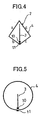
- Example 3 is also a modified example in which the pattern of Example 1 was modified such that the length of the first element 3 is modified to a length corresponding to 1/4 of the wavelength of the transmission and reception radio wave, the full circumferential length of the second element 4 was to a length corresponding to one wavelength, and furthermore, the shape of the second element 4 was formed into a deformed quadrangular shape as shown in Fig. 4, an antenna pattern so formed being used as an antenna for portable telephones with a frequency bandwidth of 2GHz band.
- the pattern so formed was printed and baked to a passenger compartment side of a sheet glass or a seal or sheet on which the pattern was printed was securely affixed to a passenger compartment side of a window glass 1 or the surface of an insulating member such as a resin body.
- the second element 4 was formed into a quadrangular shape which have four angular corners at upper and lower and left and right ends and which was symmetrical transversely.
- the full circumferential overall length of the second element 4 was a length equal to one wavelength, here, 1900MHz, that is, 80mm, upper left and right inclined sides a, d were 24mm long, respectively, and lower left and right inclined sides b, c were 16mm long, respectively, whereby the second element 4 was formed into a deformed quadrangular shape with a full circumferential length of 80mm.
- the second feeding point 11 was provided at the position of an intersecting point where the lower inclined sides b, c of the second element 4 intersect each other.
- an internal conductor line 12a of a coaxial cable 12 was connected to the first feeding point 10 and an external conductor line 12b was connected to the second feeding point 11.
- the antenna 2 in which the first element 3 and the second element 4 are disposed as has been described above was tuned so as to obtain a high transmission and reception gain in portable telephones with a frequency band of 2GHz, and as a result, it has been found out that a good transmission and reception performance which is similar to that obtained in Example 1 was obtained and hence that the antenna 2 of the invention was good enough to be put to practical use.
- Example 4 provides an antenna for use for the UHF band in the television broadcast, in which a first feeding point 10 and a second feeding point 11 were provided in such a manner that the second feeding point 11 was situated close to a lower portion of the first feeding point 10, a first element 3 was extended from the first feeding point 10 in a perpendicular direction to form a perpendicular line whose length corresponds to 1/4 of the wavelength of radio wave to be transmitted and received, and a second element 4 was provided in such a manner as to surround the first element 3 from the second feeding point 11 with a full circumferential length corresponding to one and a half the wavelength.
- the pattern so formed was directly printed and baked to a passenger compartment side of a sheet glass or a seal or sheet on which the pattern was printed was securely affixed to a passenger compartment side of a window glass or the surface of an insulating member such as a resin body.
- the length of the first element 3 became 1/4 of the wavelength of the transmission and reception radio wave, that is, 75mm
- the full circumferential overall length of the second element 4 was a length equal to one and a half the wavelength, here, 500MHz, that is, the second element 4 was formed into a circular shape with a full circumferential overall length of 540mm.
- an internal conductor line 12a of a coaxial cable 12 was connected to the first feeding point 10 and an external conductor line 12b was connected to the second feeding point 11.
- the antenna 2 in which the first element 3 and the second element 4 are disposed as has been described above was tuned so that the reception gain for frequencies of 470 to 770MHz in the UHF band in the TV broadcast was increased.
- Fig. 10 shows a change in reception gain when the overall length of the second element 4 is changed, and according to the figure, it is seen that a good reception characteristic can be obtained when the overall length of the second element 4 is equal to or greater than one wavelength.
- Fig. 11 shows a change in gain which changes depending on the spacing between the first element 3 and the second element 4, and it is seen that a good reception characteristic can be obtained when the first element 3 and the second element 4 were provided spaced apart from each other with a spacing of 1/32 or greater of the wavelength.
- Example 5 provides an antenna for use for the VHF-high band in the television broadcast, in which a first feeding point 10 and a second feeding point 11 were provided in such a manner that the second feeding point 11 was situated close to a left-hand side portion of the first feeding point 10, a first element 3 was extended horizontally rightwards from the first feeding point 10 in a transverse direction to form a horizontal line whose length corresponds to 1/4 of the wavelength of radio wave to be transmitted and received, and a second element 4 was provided in such a manner as to surround the first element 3 from the second feeding point 11 to thereby formed into a rectangular shape with a full circumferential length corresponding to one wavelength.
- the length of the first element 3 became 1/4 of the wavelength of the transmission and reception radio wave, that is, 250mm, and this first element 3 was provided in the horizontal direction to thereby form a horizontal line.
- the full circumferential overall length thereof was the length equal to one wavelength of the transmission and reception radio wave, and assuming that the wavelength compaction ratio of the glass plate in a frequency of 200MHz is 0.7, the second element 4 was formed into a rectangular shape in which the full circumferential length became 1040mm, vertical sides a, c were 100mm long, respectively, and horizontal sides b, d were 420mm, respectively.
- a second feeding point 11 was provided substantially at an intermediate position along the length of a vertical side a of the second element 4.
- the antenna pattern of the invention was screen printed using a conductive paste on the surface of a window glass 1 and was then calcined to thereby form a window glass with the antenna. Then, after the window glass 1 so produced had been mounted in a side window of a vehicle, an internal conductor line 12a of a coaxial cable 12 was connected to the first feeding point 10 and an external conductor line 12b was connected to the second feeding point 11.
- the antenna 2 in which the first element 3 and the second element 4 are disposed as has been described above was tuned so as to obtain a high transmission and reception gain as an antenna for frequencies of 170 to 222MHz in the VHF-high band in the TV broadcast, and as a result, it has been found out that a good transmission and reception performance which is similar to that obtained in Example 1 was obtained and hence that the antenna 2 of the invention was good enough to be put to practical use.
- Example 6 provides an antenna for use for a band in the FM radio broadcast and the VHF-Low band in the television broadcast, in which a first feeding point 10 and a second feeding point 11 were provided in such a manner that the second feeding point 11 was situated close to a left-hand side portion of the first feeding point 10, and a first element 3 was provided which was formed into a crank-like shape by extending a horizontal line e 1 rightwards from the first feeding point 10, providing a vertical line e 2 from a distal end of the horizontal line e1 and furthermore, providing a horizontal line e 3 from a distal end of the vertical line e 2 , the length of the first element 3 being a length corresponding to 1/4 of the wavelength of radio wave to be transmitted and received.
- a second element 4 was provided in such a manner as to surround the crank-shaped line of the first element 3 from the second feeding point 11 to thereby formed into an L-like shape with a full circumferential length corresponding to one wavelength.
- the antenna of the invention is such as to be used as an antenna whose frequency band corresponds to the band in the FM radio broadcast and the VHF-Low band in the television broadcast, and the pattern formed as has been described above was printed and baked to a passenger compartment side of a sheet glass or a seal or sheet on which the pattern was printed was securely affixed to a passenger compartment side of a window glass or the surface of an insulating member such as a resin body.
- the second feeding point 11 was provided at a position 75mm apart from a lower end of a left vertical side a of the second element 4, and the first feeding point 10 was provided at a position which is close to a right side of the second feeding point 11.
- the vertical line e 2 is such as to be provided between the vertical line a 1 and the vertical line c 1 with a spacing of 75mm in parallel therewith, and the horizontal line e 3 was provided between the horizontal line b 2 and the horizontal line d with a spacing of 75mm in parallel therewith.
- the antenna pattern of the invention was screen printed using a conductive paste on the surface of a window glass 1 and was then calcined to thereby form a window glass with the antenna. Then, after the window glass 1 so produced had been mounted in a side window of a vehicle, an internal conductor line 12a of a coaxial cable 12 was connected to the first feeding point 10 and an external conductor line 12b was connected to the second feeding point 11.
- the antenna 2 of Example 6 was tuned so as to obtain a high transmission and reception gain as an antenna for the band in the FM radio broadcast and the VHF-Low band in the television broadcast, and as a result, it has been found out that a good transmission and reception performance which is similar to those obtained by the other Examples was obtained and hence that the antenna 2 of the invention was good enough to be put to practical use.
- Example 7 is a modified example in which the pattern of Example 1 is modified.
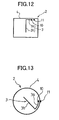
- Example 7 differs from Example 1 shown in Fig. 2 are that the shape of the first element 3 was modified to an L-like shape as shown in Fig. 12, that the linear portion (a first linear portion 3a) which corresponds to the length of 1/8 or smaller of the wavelength of the transmission and reception radio wave from a side of the first element 3 which faces the first feeding point 10 was modified to have a capacity combination with the second element 4, and furthermore that the full circumferential length of the second element 4 was modified to a length which corresponds one and a half the wavelength of the transmission and reception radio wave.
- the first linear portion 3a which was extended horizontally from the first feeding point 10 was made to become close to a horizontal line of the rectangular closed loop line which is at an upper side of the second element 4 for a capacity coupling, and a second linear portion 3b was extended downwards from a distal end of the first linear portion 3a, so that the second linear portion 3b extends away from the upper side of the second element 4.
- the length of the first element 3 was 1/4 of the wavelength of the transmission and reception radio wave, and the length of the first linear portion 3a was equal to or shorter than 1/8 of the wavelength of the transmission and reception radio wave.
- the full circumferential length of the second element 4, which was provided in such a manner as to surround the first element 3, was one and a half the wavelength, and an antenna pattern so formed was then provided on a passenger compartment side of a sheet glass.
- the length of the first element 3 became a length equal to 1/4 of the wavelength of the transmission and reception radio wave from the first feeding point 10, assuming that the wavelength compaction ratio of the glass plate in the frequency of 800MHz is 0.6, that is 55mm, the length of the first linear portion 3a was 15mm and the length of the second linear portion 3b, which was extended perpendicularly from the distal end of the first linear portion 3a, was 40mm.
- the length of the second element 4 was set to a length that corresponds to one and a half the wavelength of a frequency of 850MHz, which is different from that of the first element 3, and assuming that the wavelength compaction ratio of the glass plate in the frequency of 850MHz is 0.6, the full circumferential length thereof became 320mm, vertical sides a, c were 60mm long, and horizontal sides b, d were 100mm long, whereby a configuration could be provided in which the antenna area was reduced compared with that of Example 1.
- a second feeding point 11 was provided above the upper side of the second element 4 and a first feeding point 10 was provided at a position which was near a lower portion of the second feeding point 11.
- the antenna pattern of the invention was screen printed using a conductive paste on the surface of a window glass 1 and was then calcined to thereby form a window glass with the antenna. Then, after the window glass 1 so produced had been mounted in a side window of a vehicle, an internal conductor line 12a of a coaxial cable 12 was connected to the first feeding point 10 and an external conductor line 12b was connected to the second feeding point 11.
- the antenna 2 in which the first element 3 and the second element 4 are disposed as has been described above was tuned so as to increase the transmission and reception gain in portable telephones with 800MHz band, and as a result, it has been found out that a good transmission and reception performance which is similar to that obtained by Example 1 was obtained and hence that the antenna 2 of the invention was good enough to be put to practical use.
- Example 8 is a modified example in which the pattern of Example 4 is modified, the resulting pattern was suitable for receiving radio waves in the VHF-HIGH band in the TV broadcast.
- Main points in which Example 8 differs from Example 4 are that the shape of the first element 3 shown in Fig. 5 was modified to an L-like shape or a V-like shape and that a linear portion (a first linear portion 3a) corresponding to a length of 1/8 or smaller wavelength of the reception radio wave from a side of the first element 3 which faces a feeding pint 10 was made to have a capacity combination with an inside of the circular second element 4.
- the first element 3 included, in the inside of the second element 4 which was formed into the closed loop line, the arc-shaped first linear portion 3a provided to extend from the first feeding point 10 provided in the vicinity of the second feeding point 11 for a capacity coupling with the second element, and a second linear portion 3b was extended from a distal end of the first linear portion 3a towards the center of the circular second element 4, so that the second linear portion 3b extended away from the second element 4.
- the length of the first element 3 in Example 8 was 1/4 of the reception radio wave, that is, a length of 250mm
- the length of the first linear portion 3a was a length equal to or smaller than 1/8 of the wavelength of the transmission and reception radio wave, which was 90mm
- the length of the second linear portion 3b which was extended from the first linear portion 3a towards the center of the second element 4, was 160mm.
- the full circumferential overall length thereof was set to a length equal to one wavelength of the reception radio wave, and assuming that the wavelength compaction ratio of the glass plate in a frequency of 200MHz is 0.7, the second element 4 was formed into a circle with a full circumferential length of 1040mm and a diameter of about 330mm.
- the antenna pattern of the invention was screen printed using a conductive paste on the surface of a window glass 1 and was then calcined to thereby form a window glass with the antenna. Then, after the window glass 1 so produced has been mounted in a side window of a vehicle, an internal conductor line 12a of a coaxial cable 12 was connected to the first feeding point 10 and an external conductor line 12b was connected to the second feeding point 11.
- the antenna 2 in which the first element 3 and the second element 4 are disposed as has been described above was tuned so as to increase the transmission and reception gain of an antenna used as one for the VHF-high band in the TV broadcast, and as a result, it has been found out that a good transmission and reception performance which is similar to that obtained by Example 5 was obtained and hence that the antenna 2 of the invention was good enough to be put to practical use.
- Example 9 is a modified example in which the pattern of Example 3 was modified such that a leading wire 4a for a second feeding point 11 of a second element 4 which was formed into a substantially rectangular closed loop line was provided to extend along the closed loop line in such a manner as to be kept close thereto inside the closed loop line with a length of 1/4 or smaller of the wavelength of radio wave to be transmitted and received, and the feeding point 11 was provided at the position of an intersecting point where lower inclined sides b, c of the second element 4 intersect each other, which position was in the vicinity of a feeding point 10.
- the length of the first element 3 was modified to a length corresponding to 1/4 of the wavelength of the transmission and reception radio wave
- the length of the closed loop portion around the full circumference of the second element 4 was to a length corresponding to double the wavelength
- the length of the leading line 4a which connects the closed loop line to the second feeding point 11 was a length of 1/4 or smaller of the wavelength of the transmission and reception radio wave, so that the resulting pattern was used for an antenna for portable telephones with a frequency bandwidth of 2GHz.
- the pattern so formed was printed and baked to a passenger compartment side of a sheet glass or a seal or sheet on which the pattern was printed was securely affixed to a passenger compartment side of a window glass 1 or the surface of an insulating member such as a resin body.
- the length of the first element 3 was 1/4 of the wavelength of the transmission and reception radio wave, that is, 18mm
- the full circumferential overall length of the second element 4 was a length equal to double the wavelength, here, 1900MHz, that is, 160mm
- upper left and right inclined sides a , d were 48mm long, respectively
- lower left and right inclined sides b, c were 32mm long, respectively, whereby the second element 4 was formed into a deformed quadrangular shape with a full circumferential length of 160mm.
- an internal conductor line 12a of a coaxial cable 12 was connected to the first feeding point 10 and an external conductor line 12b was connected to the second feeding point 11.
- the antenna 2 in which the first element 3 and the second element 4 are disposed as has been described above was tuned so as to obtain a high transmission and reception gain in portable telephones with a frequency band of 2GHz, and as a result, it has been found out that a good transmission and reception performance which is similar to that obtained in Example 3 was obtained and hence that the antenna 2 of the invention was good enough to be put to practical use.
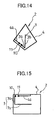
- Example 10 provides a modified example in which the pattern of Example 7 was modified such that as shown in Fig. 15, a leading line 4a for a second feeding point 11 of a second element 4 was provided to extend along a closed loop line in such a manner as to be kept close thereto inside the closed loop line with a length of 1/4 or smaller of the wavelength of radio wave to be transmitted and received.
- the length of a first element 3 was modified to a length corresponding to 1/4 of the wavelength of the transmission and reception radio wave
- the length of a closed loop portion around the full circumference of the second element 4 was to a length corresponding to one wavelength
- the length of the leading line 4a which connects the closed loop line to the second feeding point 11 was a length of 1/4 or smaller of the wavelength of the transmission and reception radio wave
- the pattern so formed was printed and backed to a passenger compartment side of a sheet glass or a seal or sheet on which the pattern was printed was securely affixed to a passenger compartment side of a window glass 1 or the surface of an insulating member such as a resin body as an antenna for frequencies of 470 to 770MHz in the UHF band in the TV broadcast.
- the length of the first element 3 was 1/4 of the wavelength of the transmission and reception radio wave, that is, 75mm
- the full circumferential overall length of the second element 4 was a length equal to the wavelength, that is, 360mm , assuming that the frequency is 500MHz.
- the antenna 2 in which the first element 3 and the second element 4 are disposed as has been described above was tuned to increase the reception gain for frequencies of 470 to 770MHz in the UHF band in the TV broadcast.
- Fig. 18 shows a change in reception gain which changes as the overall length of the second element 4 changes, and according to the figure, it is seen that a good reception characteristic was obtained when the overall length of the second element 4 was equal to or greater than one wavelength.
- Fig. 19 shows a change in reception gain which changes as the length of the linear portion (the first linear portion 3a) of the first element 3 which is close to the second element 4 changes, and it is seen that a good reception characteristic could be obtained when the length of the first linear portion 3a was equal to or smaller than 1/8 of the wavelength of the transmission and reception radio wave.
- Example 11 is a modified example in which the pattern of Example 7 was modified.
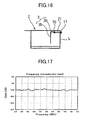
- Example 11 differs from Example 7 are that while a first feeding point 10 and a second feeding point 11 were not close to each other, instead of this, as shown in Fig. 16, a terminal metallic fixture portion of a metallic terminal 21 which was placed on and fixed to the second feeding point 11 was provided in such a manner as to be close to the first feeding point 10, so that the two feeding points were made to become close to each other substantially, that a horizontal auxiliary line was provided to extend from an upper left-hand side corner portion of a second element 4, and that two lines were provided as a bottom side line of the second element 4, and the other features remained substantially the same as those of Example 7.
- a first element 3 was modified to a length which corresponds to 1/4 of the wavelength of a radio wave to be received, the full circumferential length of the second element 4 was to a length which corresponds to a length equal to one wavelength, and furthermore a pattern resulting from the modification was used as an antenna for frequencies of 470 to 770MHz in the UHF band in the TV broadcast.
- the pattern so produced was then printed and baked to a passenger compartment side of a sheet glass or a seal or sheet on which the pattern was printed was securely affixed to a passenger compartment side of a window glass 1 or the surface of an insulating member such as a resin body.
- an internal conductor line 12a of a coaxial cable 12 was connected to the first feeding point 10 and an external conductor line 12b was connected to the second feeding point 11.
- the antenna 2 which is disposed as has been described above was tuned so as to obtain a high reception gain in frequencies of 470 to 770MHz in the UHF band in the TV broadcast, and as a result, it has been found out that a good reception performance which is similar to that obtained by Example 7 was obtained and hence that the antenna 2 of the invention was good enough to be put to practical use.
- a feeding point was provided in the vicinity of each of upper left-hand side and right-hand side inner corners of a second element 4 which was a substantially quadrangular closed loop line, and first elements 3, 3' were provided from the two left and right first feeding points 10, 10', respectively, and patterns of the two first elements 3, 3' were made transversely symmetrical with each other.
- two second feeding points 11, 11' were provided for the closed line of the second element 4, and the two feeding points 11, 11' were provided on the closed loop line which was the second element 4 or connected thereto via leading lines while being situated at positions which were in the vicinity of the first feeding points 10, 10', respectively.
- the first element 3, which is one of the first elements 3, 3', and the closed loop second element 4 as seen from the second feeding point 11 are used as an antenna for frequencies of 470 to 770MHz in the UHF band in the TV broadcast, whereas the other first element 3' and the closed loop second element 4 as seen from the second feeding point 11' were used similarly as an antenna for frequencies of 470 to 770MHz in the UHF band in the TV broadcast, whereby the antenna 2 was made as a two-system antenna.
- the lengths of the respective first elements 3, 3' were a length which corresponds to 1/4 of the wavelength of a radio wave to be transmitted and received, and the length of a closed loop portion of the second element 4 was a length which corresponds to one and a half the wavelength.
- the lengths of the two first elements 3, 3' each became 1/4 of the wavelength of the transmission and reception radio wave, that is, 75mm, and the full circumferential overall length of the second element 4 became one and a half the wavelength, that is, 540mm, assuming that the frequency is 500MHz.
- an internal conductor line 12a and an external conductor line 12b of a coaxial cable 12 were connected, respectively, to the first feeding point 10, which is one of the first feeding points, and the second feeding point 11, which was one of the second feeding points, and furthermore, an internal conductor line 12a and an external conductor line 12b of the coaxial line 12 were connected to the other first feeding point 10' and the other second feeding point 11'.
- the antenna 2 in which the first elements 3, 3' and the second element 4 are disposed as has been described above is tuned to increase the reception gain in frequencies of 470 to 770MHz in the UHF band in the TV broadcast.
- the exclusive area where the second element 4 was provided can be halved compared with a case where two closed loop antennas were provided in separate areas.
- Example 13 shown in Fig. 21 is a modified example from the aforesaid Example 12 which was modified such that a first element 3 was provided at two locations within a substantially quadrangular closed loop linear element, and in total, two left and right first feeding points 11, 11' for the closed loop line 4 were provided, respectively, at positions in the vicinity of first feeding points 10, 10' ,which are feeding points for the two first elements 3, 3'.
- One of the two first elements was used as an antenna for portable telephones with a band of 800MHz, and the other first element 3' was used as an antenna for portable telephones with a band of 2GHz, whereby the resulting antenna was made as a two-system antenna.
- each of the two feeding points 11, 11' was connected to the closed loop line which is the second element 4 via leading lines which were drawn therefrom, and the closed loop line of the second element 4 is shared by them.
- the lengths of the respective first elements 3, 3' were set to a length which corresponds to 1/4 of the wavelength of a radio wave to be transmitted and received, and the length of a closed loop portion of the second element 4 was set to a length which corresponds to one and a half the wavelength for the frequency of 800MHz band and to a length which corresponds to four wavelengths for the 2GHz band.
- the wavelength compaction ratio of the glass plate in the frequency of 800MHz band is 0.6 and the wavelength compaction ratio of the glass plate in the frequency of 2GHz band is 0.5
- the lengths of the two first elements 3, 3' each became 1/4 of the wavelength of the transmission and reception radio wave, that is, 55mm, 18mm
- the full circumferential overall length of the second element 4 became one and a half the wavelength for the 800MHz band and four wavelengths for the 2GHz band, that is, 320mm.
- an internal conductor line 12a and an external conductor line 12b of a coaxial cable 12 were connected, respectively, to the first feeding point 10, which is one of the first feeding points, and the second feeding point 11, which is one of the second feeding points, and furthermore, an internal conductor line 12a and an external conductor line 12b of the coaxial line 12 were connected to the other first feeding point 10' and the other second feeding point 11'.
- the respective antennas in which the first elements 3, 3' and the second element 4 are disposed as has been described above was tuned so as to increase reception gains in the portable telephone frequencies of 800MHz and 2GHz bands, and as a result, it has been found out that a good transmission and reception performance is obtained and hence that the antennas were good enough to be put to practical use.
- Fig. 23 is an example in which an antenna 102 of the invention as shown in Fig. 24 was provided on a side window glass 101 of a vehicle, which is then seen from the outside of the vehicle.
- a second feeding point 110 of a horizontally elongated rectangular second element 104 which is an outer element and is formed into a closed loop shape was provided at a position near an upper left-hand side corner of the second element 104.
- a first element 103 which is an inner element, was provided as a spiral shape which extends in a clockwise direction from a first feeding point 111 which was provided inside the second element 104 at a position in the vicinity of the second feeding point 110 along an inner side of the second element 104.
- An antenna 102 of the invention which is made up of the first element 103 and the second element 104 is an antenna which is effective when used for, in particular, the frequency of 470 to 770MHz in the UHF bandwidth in the TV broadcast.
- the overall length of a line of the second element 104 was one and a half the wavelength of a radio wave to be transmitted and received, that is, assuming that the wavelength compaction ratio of the glass plate in the frequencies of 470 to 770MHz in the UHF band in the TV broadcast is 0.6, the full circumferential length became about 450mm in the frequency of 600MHz, vertical sides a, c were 65mm long and horizontal sides b, d were 160mm long.
- the overall length of a line of the first element 103 was 5/4 of the wavelength of the reception radio wave, that is, assuming that the wavelength compaction ratio of the glass plate in the frequencies of 470 to 770MHz in the UHF band in the TV broadcast is 0.6, a length of 390mm.
- the overall length of the line of the first element 103 while the overall length was set to a length which corresponds to 5/4 of the wavelength of the reception frequency, in the event that the overall length thereof was attempted to match a length equal to 5/4 wavelengths of a frequency of 580MHz which is different from the frequency band of the second element 104 in order to increase the gain over a wide band, a good result was obtained.
- spacings between the upper side d of the second element 104 and an upper side of the first element 103 and between the lower side b of the second element 104 and a lower side of the first element 103 were 5mm
- spacings between the left side a of the second element 104 and a left side of the first element 103 and between the right side c of the second element 104 and a right side of the first element 103 were 10mm.
- the line widths of the respective lines of the first element 103 and the second element 104 were a line width of 1mm.
- a distance between an antenna 102 of the Example thus produced and a flange of a window glass of the vehicle was 15mm at a nearest portion.
- the antenna pattern of the invention was screen printed using a conductive paste on the passenger compartment side of the window glass 101 and was then calcined to thereby form a window glass with the antenna. Then, after the window glass 101 so produced had been mounted in a side window of a vehicle, an external conductor line 112b of a coaxial cable 112 was connected to the second feeding point 110 and an internal conductor line 112a was connected to the first feeding point 111.
- the antenna 102 in which the first element 103 and the second element 104 are disposed as has been described above was tuned so as to increase the reception gain in frequencies of 470 to 770MHz in the UHF band in the TV broadcast, and as result, it has been found out when the result is represented by the dipole ratio that, as is clear from a frequency characteristic chart shown in Fig 28, a good result of -9.7dB on the average in the UHF band was obtained which highly exceeds -20.0dB which is the average of conventional glass antennas which have been in practical use.
- the antenna shown in Fig. 24 which was obtained as has been described above could provide an antenna which experiences almost no change in antenna impedance even in such a state that there are occupants in the vehicle and which does not deteriorate the field of vision due to the simple construction thereof and the gain thereof is sufficiently high, and hence the antenna so obtained was such as to be good enough to be put to practical use.
- this example is a modified example from Example 14 in which a second feeding point 110 of a vertically elongated rectangular second element 104 which is an outer element and is formed into a closed loop shape was provided at a position near an upper right-hand side corner of the second element 104.
- a first element 103 which is an inner element, was provided as an L-like shape or U-like shape which extends in a clockwise direction from a first feeding point 111 which was provided inside the second element 104 at a position in the vicinity of the second feeding point 110 along an inner side of the second element 104 and constitutes an antenna which is effective when used in particular for an antenna for a mobile communication band in frequencies of 800MHz to 960MHz.
- a horizontal line of the first element 103 which is close to a lower side b of the second element 104 is an element which is mainly formed into a U-like shape which is formed by extending a horizontal line from a right-hand side corner of the lower side of the second element 104 along the same lower side to an intermediate position along the length of the lower side and extending a vertical line upwards from a distal end portion of the horizontal line
- an auxiliary line 5 may be provided which branches off a distal end of the horizontal line to extend towards the vicinity of a left-hand side corner of the lower side of the second element 104.
- a total length of main constituent lines of the first element 103 was made to correspond to 3/4 of the wavelength of radio wave to be transmitted and received.
- auxiliary line 5 can adjust the impedance of the first element 103.
- the overall length of a line of the second element 104 was one and a half the wavelength of the transmission and reception radio wave, that is, assuming that the wavelength compaction ratio of the glass plate in the frequencies of 800MHz to 960MHz in the mobile communication is 0.6, the full circumferential length became about 310mm in the frequency of 850MHz, vertical sides a, c were 95mm long and horizontal sides b, d were 65mm long.
- the overall length of a line of the first element 103 was 3/4 of the wavelength of the transmission and reception radio wave, that is, assuming that the wavelength compaction ratio of the glass plate in the frequencies of 800MHz to 960MHz is 0.6, was made as a line with a length of 169mm.
- the overall length of the line of the first element 103 while the overall length was set to a length which corresponds to 3/4 of the wavelength of the transmission and reception frequency, in the event that the overall length thereof was attempted to match a length equal to about 3/4 wavelength of a frequency of 800MHz which is different from the frequency band of the second element 104 in order to increase the gain over a wide band, a good result was obtained.
- a spacing between the second feeding point 110 and the first feeding point was 3mm
- a spacing between a lower side b of the second element 104 and a lower side of the first element 103 was 3mm
- a spacing between a right side c of the second element 104 and a right side of the first element 103 was 3mm
- a spacing between a left side a of the second element 104 and a left side of the first element 103 was 22mm.
- a distance between an antenna 102 thus formed and a flange of a window glass of the vehicle was 15mm at a nearest portion.
- the antenna pattern of the invention is screen printed using a conductive paste on a passenger compartment side of a window glass 101 and was then calcined to thereby form a window glass with the antenna, or a seal or sheet on which the pattern was printed was securely affixed to the passenger compartment side of the window glass 101 or the surface of an insulating member such as a resin body.
- an external conductor line 112b of a coaxial cable 112 was connected to the second feeding point 110 and an internal conductor line 112a was connected to the first feeding point 111.
- the first element 103 was provided to extend from the first feeding point 111 along an inside of the second element 104 and the overall length of the first element 103 was set to a length corresponding to 3/4 of the wavelength of the transmission and reception frequency, here, in order to increase the gain over frequencies of 900 to 960MHz, the overall length of the first element 103 can be made to match a length equal to 3/4 wavelength of a frequency of 900MHz.
- the wavelength compaction ratio of the glass plate in the frequency of 900MHz is about 0.5
- the length of the right side of the element 103 is 89mm
- the length of the bottom side of the element 103 is 40mm
- the length of a portion which is directed upwards from a distal end portion of a horizontal line extended from a right-hand side corner on the lower side of the element 103 along the lower side of the second element 104 is 25mm
- the whole length forms the U-like shape of 150mm.
- an external conductor line 112b of the coaxial cable 112 was connected to the second feeding point 110, and an internal conductor line 112a was connected to the first feeding point 111.
- the antenna 102 in which the first element 103 and the second element 104 are disposed as has been described above was adjusted with a view to increasing the transmission and reception gain in the frequencies of 800MHz to 960MHz in the mobile communication band.
- Example 16 is a modified example in which the pattern of Example 14 was modified, in which a second element 104, which is an outer element, is formed into a substantially rhombic shape which has four corners in upper and lower ends and left and right ends thereof and which is transversely symmetrical, and a second feeding point 110 is provided at a lowermost end position thereof.
- a second element 104 which is an outer element
- a first element 103 which is an inner element, was provided to form a U-like shape which was extended in a clockwise direction from a first feeding point 111 provided at an upper side position which is close to the second feeding point 110 along an inside of the second element 104.
- the length of the second element was set to a length corresponding to two wavelengths of radio wave to be transmitted and received, the full circumferential length of the first element 103 was set to a length corresponding to 5/4 wavelengths, and the shape of the second element 104 was formed into a deformed quadrangular shape as shown in Fig. 26, an antenna thus formed constituting an antenna for use as one in frequencies of 1900 to 2200MHz in the mobile communication.
- the pattern so formed was printed and baked to a passenger compartment side of a sheet glass or a seal or sheet on which the pattern was printed was securely affixed to a passenger compartment side of a window glass 101 or the surface of an insulating material such a resin body.
- the length of the second element 104 became two wavelengths of radio wave to be transmitted and received, that is, the full circumferential length thereof became about 154mm in a frequency of 1950MHz, upper left and right inclined sides a, d were 46mm long, lower left and right inclined sides b, c were 31mm long, the second element was thus formed into the deformed quadrangular shape with a full circumferential length of 154mm, and the full circumferential overall length of the first element 103 was a length equal to 5/4 wavelengths, that is, about 89mm here for a frequency of 2100MHz.
- an external conductor line 112b of a coaxial cable 112 was connected to the second feeding point 110 and an internal conductor line 112a was connected to the first feeding point 111.
- the antenna 102 in which the first element 103 and the second element 104 are disposed as has been described above was adjusted with a view to increasing the transmission and reception gain of the antenna in the frequencies of 1900 to 2200MHz in the mobile communication band. As a result, it has been found out that a good transmission and reception performance that the average reception gain is -8.2dB was obtained and that the antenna was good enough to be put to practical use.
- a second element 104 which is an outer element, is a circular linear element, and a second feeding point 110 is provided at a lowermost end position of the circular linear element.
- a first element 103 which is an inner element, was provided to form an arc-like shape resulting by cutting part a circular shape which was extended in a counterclockwise direction from a first feeding point 111 provided at an upper side position which is close to the second feeding point 110 along an inside of the second element 104.
- the length of the second element 104 was set to a length corresponding to one wavelength of radio wave to be transmitted and received, the full circumferential length of the first element 103 was set to a length corresponding to 3/4 wavelength, and furthermore, the shape of the second element 104 was formed into a circular shape as shown in Fig. 27 and the shape of the first element 103 was formed into the arc-like shape resulting by cutting part of a circular shape, an antenna thus formed constituting an antenna for use as one in frequencies of 170 to 230MHz in the VHF-HIGH band in the TV broadcast.
- the pattern so formed was printed and baked to a passenger compartment side of a sheet glass or a seal or sheet on which the pattern was printed was securely affixed to a passenger compartment side of a window glass 101 or the surface of an insulating material such a resin body, and thereafter, an external conductor line 112b of a coaxial cable 112 was connected to the second feeding point 110 and an internal conductor line 112a was connected to the first feeding point 111.
- the length of the second element 104 became one wavelength of radio wave to be transmitted and received, that is, the full circumferential length thereof became about 1040mm in a frequency of 200MHz
- the full circumferential overall length of the first element 103 was a length equal to 3/4 wavelength, that is, about 750mm here for a frequency of 210MHz, which covers the arc-like shape of the first element 103.
- the antenna 102 in which the first element 103 and the second element 104 are disposed as has been described above was tuned with a view to increasing the reception gain in the frequencies of 170 to 230MHz in the TV broadcast.
- the invention can preferably be used in transmitting and receiving radio waves of very-high-frequencies and ultrahigh frequencies such as for personal radio communications, commercial radio communications and PHS.
- the antenna of the invention is used by directly printing its antenna patterns on a window glass surface of a rear window glass at upper and lower portions remaining unused for defogger heater lines, a windshield, a side window glass and a roof window glass or by printing the same on a film-like seal or sheet so as to be securely affixed to a passenger compartment side of the window glass or an insulating body member of a movable body.
- the antenna of the invention can be used independently, more preferable effects can be obtained when the antenna is used as those glass antennas, seal antennas in which the antenna is printed on a seal or sheet so as to be securely affixed to an insulating member of the movable body or is used together with a rod antenna for diversity reception.
- the feeding terminals of the antenna 2 and a tuner are described as being connected to each other with a coaxial cable, in the event that an impedance matching circuit and a circuit such as an amplifier, which are not shown, are interposed for connection between the feeding terminals of the antenna 2 and the tuner, much more preferable effects can be obtained.
Landscapes
- Details Of Aerials (AREA)
Abstract
The invention relates to a vehicular antenna which is a
line antenna provided on the surface of a window glass or the
like of a vehicle or the like, provided with a first element
which is extended from a first feeding point and which has a
length of either 1/4, 3/4 or 5/4 of the wavelength of radio wave
to be transmitted and received and a second element formed into
a closed loop which is extended from a second feeding point which
is provided in the vicinity of the first feeding point in such
a manner as to surround the first element and which has a length
equal to or longer than one wavelength of the transmission and
reception radio wave.
Description
The present invention relates to a line antenna provided
on the surface of a window glass or the surface of an insulating
member of a movable body such as a vehicle, which is preferable
for use in receiving FM radio broadcast waves, digital radio
broadcast waves and television broadcast waves, as well as in
transmitting and receiving radio waves of very-high-frequency
range or higher such as of car telephones, portable telephones,
personal radio communication equipment, commercial radio
communication equipment and PHS (Personal Handy Phone System).
Conventionally, while rod antennas have been widely used
as antennas for transmitting and receiving radio waves of car
telephones and portable telephones and receiving television
broadcast waves, since the construction of these rod antennas
requires them to protrude from the vehicle body, there have been
caused drawbacks that the protrusion of the antennas is not
preferable from safety and aesthetic appearance aspects and
that the protruding antenna constitutes a disturbance and may
be broken when washing a vehicle.
Due to this, in recent years, there have been demands for
antennas with no protrusion such as glass antennas in which an
antenna pattern is directly printed on a window glass of a
vehicle and antennas in which a seal or sheet on which an antenna
pattern is printed is affixed to a window glass of a vehicle,
and those antennas have now been put to practical use.
Some of such glass antennas and seal antennas which are
now in practical use as car and portable telephone antennas have
practically the same transmission and reception gain
performance as that of rod antennas.
For example, JP-A-06-152216 discloses a glass antenna for
car telephones which is characterized by the inclusion of a
radiation pattern whose length in a vertical direction on the
surface of a window glass is approximately 1/4 of the wavelength
and a ground pattern whose length in a horizontal direction on
the surface of the window glass is approximately 1/4 of the
wavelength, wherein the ground pattern is provided on at least
one of left and right ends of the window glass surface in such
a manner that when the ground pattern is provided on the left
end, the radiation pattern is provided so as to be close to a
left-hand side portion of the ground pattern, whereas when the
ground pattern is provided on the right end, the radiation
pattern is provided so as to be close to a right-hand side portion
of the ground pattern, so that the ground pattern is formed into
a ring-like shape (Patent Document No. 1).
In addition, JP-A-06-314921 discloses a glass antenna
provided on a vehicular window glass which is characterized by
the inclusion of at least a first element in which a horizontal
line is connected to a distal end of a vertical line and a second
element in which a horizontal line connected to a distal end
of a vertical line and another horizontal line are provided so
as to be close to each other vertically in such a manner as to
hold the horizontal line of the first element therebetween, so
that an end portion of the first element is encompassed by the
two horizontal lines (Patent Document No. 2).
Furthermore, JP-A-08-148921 discloses a glass antenna
system for car telephones formed by using a conductor pattern
on a vehicle window glass which is characterized by being made
up of a circular radiation pattern and a doughnut-like shaped
ground pattern provided concentrically on an outside of the
radiation pattern (Patent Document No. 3).
On the other hand, glass antennas which are now in
practical use as vehicular glass antennas for reception of
television broadcast waves have practically the same reception
performance and gain as those of rod antennas and are disclosed.
For example, JP-A-07-263934 discloses a vehicular glass
antenna provided on an upper unused portion on a vehicular rear
window glass in which a defogging heater line is embedded which
is characterized by the inclusion of a first antenna made up
of a horizontal line and a vertical line and a second antenna
provided in an unused portion of the first antenna in a left
half or right half of the rear window glass in which a line is
provided to extend perpendicularly from part of a main element
mainly made up of a horizontal line, a transversely elongated
rectangular element is connected to the perpendicularly
extending line, and a line is drawn out of part of a short side
of the rectangular element for implementing a feeding at the
side portion of the element (Patent Document No. 4).
In addition, JP-A-2001-119223 discloses a glass antenna
provided on a vehicular side window for preferably receiving,
in particular, TV radio waves of all bands (Patent Document No.
5).
Furthermore, JP-A-2001-332923 discloses a film antenna
in which a rectangular flat plate-like film antenna element is
provided on a glass supported by a conductive frame unit for
preferably receiving TV radio waves of all bands (Patent
Document No. 6).
However, since the antenna performance of any of the car
telephone or portable telephone glass antennas shown in Patent
Document No 1 to Patent Document No. 3 and the TV broadcast waves
reception glass antennas shown in Patent Document No. 4 to
Patent document No. 6 is liable to be affected by locations where
the antenna is placed or structures in the vicinity of the
antenna so placed, antenna elements and antenna setting
positions must be adjusted vehicle by vehicle. Further, even
in case such adjustments are carried out accordingly, the
antenna performance has still been changed by the effect of
human bodies.
In addition, the car telephone or portable telephone
glass antennas shown in Patent Document No. 1 to Patent Document
No. 6 have low gains compared with the rod antennas, and hence
a further improvement in antenna gain has been desired.
Furthermore, as to the TV broadcast waves reception glass
antennas shown in Patent Document No. 4 to Patent Document No.
6, not only does a grounding need to be provided in the vicinity
of an antenna feeding point but also antenna setting conditions
are limited with respect to reception frequencies. In
particular, the antenna has to be provided limitedly on the rear
window of the vehicle in Patent Document No. 4, on a side window
of the vehicle in Patent Document No. 5 and on a large window
or door of a structure such as a building in Patent Document
No. 6.
In particular, as to the TV broadcast waves reception
antennas shown in Patent Document No. 4 to Patent Document No.
5, it was difficult to match the impedance of the antenna to
the impedance of the receiver over all the bands of TV broadcast
waves to be received.
The invention was made in view of the problems, and an
object thereof is to provide a vehicular antenna which can make
it difficult for the antenna performance thereof to be affected
by antenna setting locations and human bodies so as to reduce
an actual antenna area while increasing the antenna performance
higher than that provided by the conventional techniques and
is hence preferable as a car telephone and portable telephone
antenna, as well as a digital broadcast waves and TV broadcast
waves reception antenna, which can, furthermore, transmit and
receive radio waves of personal radio communication equipment,
commercial radio communication equipment and PHS, and which can,
moreover, be made difficult to be bound by a position on the
surface of a window glass where the antenna is provided.
Namely, according to the invention, there is provided a
vehicular antenna which is a line antenna provided on a surface
of a window glass or a surface of an insulating member of a
movable body such as a vehicle, provided with a first element
which is extended from a first feeding point and which has a
length of either 1/4, 3/4 or 5/4 of the wavelength of radio wave
to be transmitted and received and a second element formed into
a closed loop which is extended from a second feeding point which
is provided in the vicinity of the first feeding point in such
a manner as to surround the first element and which has a length
equal to or greater than one wavelength of the transmission and
reception radio wave.
Alternatively, according to the invention, there is
provided a vehicular antenna as set forth above, in which a
linear portion which is extended from the first feeding point
of the first element includes a first linear portion which
extends close to a closed loop line of the second element with
a length of 1/8 or shorter of the wavelength of the transmission
and reception radio wave for a capacity coupling and a second
linear portion which is extended from a distal end of the first
linear portion in a direction in which the second linear portion
extends away therefrom.
In addition, alternatively, according to the invention,
there is provided a vehicular antenna as set forth above, in
which a portion which is spaced apart along a linear portion
extended from the second feeding point of the second element
by 1/4 of the wavelength of the transmission and reception radio
wave is provided 1/32 or longer of the wavelength apart from
an opposite end portion to the first feeding point of the first
element.
In addition, alternatively, according to the invention,
there is provided a vehicular antenna as set forth in any of
the above vehicular antennas, in which a feeding point for the
second element formed into the closed loop is provided at a
distal end of a leading line along the closed loop, the length
of the leading line being made to be 1/4 or shorter of the
wavelength of the transmission and reception radio wave.
In addition, alternatively, according to the invention,
there is provided a vehicular antenna as set forth in any of
the vehicular antennas, in which, instead of placing the first
feeding point and the second feeding point close to each other,
a metallic terminal is placed on at least either of the first
feeding point and the second feeding point, so that either the
feeding point or the metallic terminal of either of the first
feeding point and the second feeding point becomes close to
either the feeding point or the metallic terminal of the other.
In addition, alternatively, according to the invention,
there is provided a vehicular antenna as set forth in any of
the vehicular antennas, in which the first linear portion which
extends from the first feeding point of the first element with
the length of 1/8 or shorter of the wavelength of the
transmission and reception radio wave becomes close to the
second element with a spacing of 0.1 to 10mm.
In addition, alternatively, according to the invention,
there is provided a vehicular antenna as set forth in any of
the vehicular antennas, in which the length of the closed loop
linear portion of the second element is equal to or longer than
one wavelength of the transmission and reception radio wave but
not in excess of four wavelengths.
In addition, alternatively, according to the invention,
there is provided a vehicular antenna as set forth above, in
which the length of the closed loop linear portion of the second
element is (1+n/2)λ (n is an integer of 0 to 6), assuming that
the wavelength of the transmission and reception radio wave is
λ.
In addition, alternatively, according to the invention,
there is provided a vehicular antenna as set forth in any of
the vehicular antennas, in which first elements are provided
at a plurality of locations inside the second element formed
into the closed loop in such a manner that respective first
feeding points of the plurality of first elements are positioned
in the vicinity of the second feeding point of the second
element.
According to the invention, there is provided a vehicular
antenna as set forth in any of the vehicular antennas, in which
the second element is formed into a closed loop of a polygonal
or arc-like shape.
Alternatively, according to the invention, there is
provided a vehicular antenna as set forth above, in which a
spacing between the first element and the second element at a
portion linearly extended from the first feeding point by a
length of 1/2 of the wavelength of the transmission and
reception radio wave is 0.5 to 10mm, when the length of the first
element is 3/4 of the wavelength of the transmission and
reception radio wave.
In addition, alternatively, according to the invention,
there is provided a vehicular antenna as set forth above, in
which a spacing between the first element and the second element
at a portion linearly extended from the first feeding point by
a length equal to one wavelength of the transmission and
reception radio wave is 0.5 to 10mm, when the length of the first
element is 5/4 of the wavelength of the transmission and
reception radio wave.
In addition, alternatively, according to the invention,
there is provided a vehicular antenna as set forth in any of
the vehicular antennas, in which the length of the second
element is increased by 1/4 or greater of the wavelength of the
transmission and reception radio wave over the length of the
first element.
In addition, alternatively, according to the invention,
there is provided a vehicular antenna as set forth in any of
the vehicular antennas, in which the length of the second
element is (1+n/2)λ (n is an integer of 0 to 4), assuming that
the wavelength of the transmission and reception radio wave is
λ.
In addition, alternatively, according to the invention,
there is provided a vehicular antenna as set forth in any of
the vehicular antennas, in which pattern of the antenna element
is directly printed on using a conductive ceramic paste or the
like or a seal or sheet on which the pattern is so printed is
securely affixed to a surface made up of a window glass or the
surface of an insulating member of a movable body such as a
vehicle.
According to the invention, the antenna can make it
difficult for the antenna performance thereof to be affected
by antenna setting locations or human bodies, and hence the
actual antenna area can be reduced.
In addition, the antenna can increase the antenna
performance higher than that provided by the conventional
techniques and is hence preferable as a car telephone and
portable telephone antenna, as well as a digital broadcast waves
and TV broadcast waves reception antenna and furthermore can
transmit and receive radio waves of personal radio
communication equipment, commercial radio communication
equipment and PHS.
Furthermore, the antenna can be provided which is
difficult to be affected by the position on the surface of the
window glass where the antenna is provided.
Moreover, the invention can provide the antenna which is
simple and compact in configuration and which has a high
performance.
In particular, the simple and high-performance antenna
can be provided for digital TV broadcast and telematics.
In addition, since the invention can be applied to not
only the glass antenna which is directly printed on the
passenger compartment side of the window glass of the vehicle
but also the so-called seal antenna which is printed on the thin
film-like seal or sheet so as to be securely affixed to the
surface of the glass window or the insulating member of the
movable body, the attachment to the vehicle can be facilitated.
Note that in the figures, reference numerals 1, 101 denote
window glasses, 2, 102 antennas of the invention, 3, 3', 103
first elements, 3a, 3'a first linear portions, 3b, 3'b second
linear portions, 4, 4', 104 second elements, 4a a leading line,
4b closed loop linear portion, 10, 10', 110 first feeding points,
11, 11', 111 second feeding points, 12, 112 coaxial cables, 12a,
112a internal conductor lines, 12b, 112b external conductor
lines, 20, 120 metallic brushes, 21, 121 metallic terminals,
and 105 an auxiliary line.
Hereinafter, a mode for carrying out the invention will
described.
A first element 3, whose length is 1/4 or 3/4 of a
wavelength of a transmission and reception radio wave, is
provided from a first feeding point 10, a second feeding point
11 is provided in the vicinity of the first feeding point 10.
A second element 4, which has a length equal to or longer than
one wavelength of the transmission and reception radio wave and
which is formed into something like a closed loop, is provided
from the second feeding point 11 in such a manner as to surround
the first element 3. An internal conductor line 12a and an
external conductor line 12b of a coaxial cable 12 are connected,
respectively, to the first feeding point 10 and the second
feeding point 11.
As shown in Figs. 12, 13, 15 and 16, the first element
10 is made up of a first linear portion 3a which is made up of,
in turn, a linear portion extended from the first feeding point
10 in such a manner as to be kept close to a closed loop line
of the second element 4 for a capacity coupling and a second
linear portion 3b which is extended from a distal end of the
first linear portion 3a to thereby by provided in a direction
in which the second linear portion 3b extends away from the
second element 4. The length of the first linear portion 3a
is preferably 1/8 or shorter of the wavelength of the
transmission and reception radio wave. While substantially
L-shaped configurations as shown in Figs. 12, 13, 15 and 16 are
shown as shapes resulting from the connection of the first
linear portion 3a and the second linear portion 3b, the first
linear portion 3a and the second linear portion 3b do not always
have to be formed into such linear shapes but may be formed into
arc-like shapes.
On the other hand, in patterns shown in Figs. 1 to 7 and
Fig. 14, the first element 3 is formed into patterns in which
the length of the first linear portion 3a extended from the first
feeding point 10 is made zero and the entirety of a line extended
from a connecting portion with the first feeding point 10 is
provided in such a manner as to extend away from the closed loop
line of the second element 4 or may be formed into a line having
a shape in which the line so extended extends in any of
perpendicular, horizontal and oblique directions, is bent into
a crank- or hook-like shape, or extends in an arc-like shape.
In addition, a portion which is positioned apart from the
second feeding point along the second element 4 by a length equal
to 1/4 of the wavelength of the transmission and reception radio
wave is preferably provided 1/32 or greater of the wavelength
of the transmission and reception radio wave apart from an
opposite end portion of the first element 3 to the first feeding
point.
Furthermore, the second element 4 has the closed loop
shape, and an outer pattern shape surrounded by the closed loop
may take an arbitrary shape such as a substantially rhombic
shape, a substantially rectangular shape, a substantially
circular shape and an L-like shape and can be changed freely
depending on positions where the second element 4 is attached.
Furthermore, as shown in Figs. 14, 15, the second element
4 may be connected to the closed loop of the second element 4
from a distal end thereof via a leading line 4a which is drawn
from the feeding point 11 along the closed loop, and as this
occurs, the length of the leading line 4a may be 1/4 or shorter
of the wavelength of the transmission and reception radio wave.
In addition, instead of placing the first feeding point
and the second feeding point close to each other, a metallic
terminal may be placed on at least one of the first feeding point
and the second feeding point, so that either the feeding point
or the metallic terminal of one of the first and second feeding
points becomes close to either the feeding point or the metallic
terminal of the other.
Namely, in place of the second feeding point 11 which is
provided in the vicinity of the first feeding point 10 as shown
in Figs. 12 to 15, a terminal metallic fixture portion of a
metallic terminal 21 which is placed on the second feeding point
11 so as to be connected and fixed thereto may be provided in
such a manner as to become close to the first feeding point 10.
Note that the first linear portion 3a, which is extended
from the first feeding point 10 of the first element 3 with the
length of one eighth or shorter of the wavelength of the
transmission and reception radio wave, is desirably close to
a closed loop linear portion 4b of the second element 4 with
a spacing in the range of 0.1 to 10mm.
In addition, while the length of the closed loop linear
portion 4b of the second element 4 is desirable to fall within
a range which is equal to or greater than one wavelength of the
transmission and reception radio wave but not in excess of four
wavelengths from the aspect of reception characteristic, in the
event that the length of the closed loop linear portion of the
second element is (1+n/2)λ (n is an integer of 0 to 6), a good
reception characteristic can be obtained.
As the vehicle window glass on which the antenna is to
be provided, the antenna may be provided on any of window glasses
of the vehicle such as windshield glass, rear window glass, and
sunroof glass, and the window glasses include not only a sheet
glass but also a transparent sheet resin or a composite unit
made of the glass sheet and the transparent sheet resin.
In addition, while in many cases, the movable body is
normally made of metal, in the event that roof, rear door and/or
part of other members thereof are made up of insulating members
such as those made of resin, and as to insulating members made
of resin such as bumpers and spoilers, the glass antenna 2 of
the invention can be provided on these insulating members.
In addition, the antenna may be such that the antenna
pattern is directly printed using a conductive paste on the
surface of a window glass 1 or a member of the body which is
made of the insulating material, or a seal or sheet on which
the antenna pattern is printed is securely affixed to the
location of the body which is made of the insulating material.
In addition, while the antenna 2 may be such as to be
provided only at a single location, in the event that the antenna
2 is provided at a plurality of locations, a diversity reception
can be realized. As this occurs, the patterns of the antennas
so provided may be the same or different.
In addition, the first element 3 may be provided at a
plurality of locations within the closed loop second element
4. The patterns of the first element 3 so provided may be the
same or different.
Furthermore, the frequency bands of the first elements
3, 3' which are provided at the plurality of locations within
the second element 4 may be the same or different.
Fig. 23 shows a front view of an antenna of the invention
which is provided on a vehicle side window glass.
An antenna 102 of the invention is made up of two elements
which are provided on the surface of a window glass 101 of a
movable body such as a vehicle or the surface of an insulating
member of the movable body. The two elements are a closed loop
second element 104 which is extended from a second feeding point
110 and a first element 103 which is extended from a first feeding
point 111 provided within the second element 104 along the
second element 104, and an external conductor line 112b and an
internal conductor line 112a of a coaxial cable 112 are
connected, respectively, to the second feeding point 110 and
the first feeding point 111.
The second element 104 is formed into a polygonal or
arc-like closed loop shape whose line length is equal to or
longer than one wavelength of a radio wave to be transmitted
and received and is longer than the line length of the first
element.
In addition, the first element 103 is provided such that
the line length thereof becomes 3/4 or 5/4 of the wavelength
of the transmission and reception radio wave so as to closer
to an inside of the second element than the first feeding point
111 provided in the vicinity of the second feeding point inside
the second element 104.
By this configuration, the area of a region surrounded
by the second element 104 becomes greater than the area of a
region surrounded by the first element 103, resulting in such
a state that the whole area surrounded by the first element 103
is covered by the region surrounded by the second element 104.
Note that when the line length of the first element 103
is 3/4 of the wavelength of the transmission and reception radio
wave, a spacing between the first element and the second element
at a position situated apart by a line length of one half the
wavelength of the transmission and reception radio wave from
the first feeding point 111 is preferably 0.5 to 10mm.
In addition, when the line length of the first element
103 is 5/4 of the wavelength of the transmission and reception
radio wave, the spacing between the first element and the second
element at a position situated apart by a line length equal to
one wavelength of the transmission and reception radio wave from
the first feeding point 111 is preferably 0.5 to 10mm.
In addition, the length of the second element 104 is
preferably longer than the length of the first element 103 by
1/4 of the wavelength of the transmission and reception radio
wave.
Furthermore, an upper limit of the length of the second
element 104 is (1+n/2)λ (n is an integer of 0 to 4), assuming
that the wavelength of the transmission and reception radio wave
is λ.
As the vehicle window glass on which the antenna is to
be provided, the antenna may be provided on any of window glasses
of the vehicle such as windshield glass, rear window glass, and
sunroof glass, and the window glasses include not only a sheet
glass but also a transparent sheet resin or a composite unit
made of the glass sheet and the transparent sheet resin.
In addition, while in many cases, the movable body is
normally made of metal, in the event that roof, rear door and/or
part of other members thereof are made up of insulating members
such as those made of resin, and as to insulating members made
of resin such as bumpers and spoilers, the glass antenna 102
of the invention can be provided on these insulating members.
In addition, the antenna may be such that the antenna
pattern is directly printed using a conductive paste on the
surface of a window glass 101 or a member of the body which is
made of the insulating material, or a seal or sheet on which
the antenna pattern is printed is securely affixed to the
location of the body which is made of the insulating material.
Note that while the line widths of conductor lines of the
first element and the second element are to be in the range of
0.1 to 10mm, the line widths are preferably of the order of 0.5
to 5mm.
In addition, while the antenna 102 may be such as to be
provided only at a single location, in the event that the antenna
102 is provided at a plurality of locations, a diversity
reception can be realized. As this occurs, the patterns of the
antennas so provided may be the same or different.
In addition, in the event that the antenna 102 of the
invention is provided on the surface of the window glass 101
of the movable body, the antenna 102 is desirably provided with
a spacing of 5mm or greater secured from the second element 104
to a flange 120 of the metallic body.
The function of the invention will be described below.
The reason why the first element 3 is desirably made to
be the line whose length is 1/4 or 3/4 of the wave length of
the transmission and reception radio wave and the second element
4 is desirably formed into the closed loop whose length is equal
to or longer than one wavelength is because the size of the
antenna is reduced by regarding the antenna as a grounded
antenna in a pseudo fashion by making the second element 104
equal or be greater in length than one wavelength of the
transmission and reception radio wave and because radio waves
can be transmitted and received as efficiently as done with the
grounded antenna by making the first element 3 the line whose
length is 1/4 or 3/4 of the wavelength of the transmission and
reception radio wave.
In addition, the electric field of a distal end portion
of the antenna which is liable to receive external effects can
be stabilized by forming the second element 4 into the closed
loop shape, thereby making it possible to reduce the effect
imposed by human bodies or the like.
In addition, while good results can be obtained on the
first element 3 which is provided as far from the second element
4 as possible as shown in Figs. 1 to 7, since the patterns shown
in Figs. 12, 13, 15 and 16 which are each made up of the first
linear portion 3a which is kept close to the closed loop line
of the second element 4 for capacity combination and the second
linear portion 3b which is extended from the distal end of the
first linear portion 3a in the direction in which the second
linear portion 3b extends away from the second element 4 can
adjust the antenna impedance, more efficient transmission and
reception can be attained.
On the other hand, the first element 3 is, as shown in
Figs. 12, 13, 15 and 16, formed into the L-like shapes in which
the linear portion is extend from the first feeding point 10
in such a manner that the first linear portion 3a, whose length
is equal to one eights or shorter of the wavelength of the
transmission and reception radio wave, is kept close to the
second element 4 for capacity combination and the second linear
portion 3b is extended from the distal end of the first linear
portion 3a in the direction in which the second linear portion
3b extends away from the second element 4, so that the length
of the second linear portion 3b which extends in the direction
in which it extends away from the second element 4 becomes short
as a result, whereby the second linear portion 3b and the second
element 4 can be disposed to be separated apart from each other
with a sufficient spacing secure therebetween, thereby making
it possible to obtain a good transmission and reception
performance even in the event that the length of the second
element 4 is reduced.
In addition, alternatively, the reason why the portion
situated apart by 1/4 of the wavelength of the transmission and
reception radio wave from the second feeding point 11 along the
second element 4 is preferably provided apart 1/32 or greater
of the wavelength of the transmission and reception radio wave
from the opposite end portion to the first feeding point 10 of
the first element 3 is because radio waves can be made to be
transmitted as far as possible and received at as far locations
as possible, and they are preferably provided as far apart from
each other as possible.
In addition, while the antenna of the invention is an
antenna having a broad-band performance, when the respective
lengths of the linear portions of the first element 3 and the
second element 4 are selected relating to an identical frequency
with respect to the transmission and reception frequency, it
is possible to obtain very high gain relating to the selected
frequency. On the other hand, while the antenna of the
invention is an antenna having a broad-band performance, by
selecting lengths of the respective lines of the first element
3 and the second element 4 in such a manner as to match different
frequencies, the antenna can be made an antenna with a higher
gain over a wide band of frequencies including frequencies
falling in between and frequencies adjacent to the selected
frequencies.
In addition, since the antenna of the invention is
regarded as the grounded antenna in a pseudo fashion by making
the length of the closed loop linear portion of the second
element 4 equal or be greater than one wavelength of the
transmission and reception radio wave, the same effect as that
provided by a configuration in which the antenna is grounded
with the metallic body can be obtained in relatively high
frequencies.
Furthermore, as shown in Figs. 14, 15, the reason why the
feeding point 11 and the closed loop line of the second element
4 are connected to each other via the leading line 4a which
extends while kept close to the closed loop line is because the
antenna impedance is adjusted, and the reason why the length
of the leading line 4a is 1/4 or smaller of the wavelength of
the transmission and reception radio wave is because the
adjustment of antenna impedance can be facilitated over a wide
band and hence a good reception gain can be obtained and because
in case the length of the leading line 4a is made longer than
1/4 of the wavelength of the transmission and reception radio
wave, the adjustment of antenna impedance becomes difficult to
be implemented over the wide band and hence a good reception
gain cannot be obtained.
In addition, as shown in Fig. 16, in the event that the
metallic fixture portion of the metallic terminal 21 is placed
on the second feeding point 11, since the metallic terminal 21
is close to the first feeding point 10, the same effect can be
obtained due to the metallic terminal 21 which is connected on
to the second feeding point becoming close to the first feeding
point 10 even in case the second feeding point 11 is not close
to the feeding point 10.
Note that in the event that the first feeding point 10
and the second feeding point 11 are grounded while they are
spaced apart from each other, while the metallic terminal 21
may be provided in such a manner that the same terminal is placed
and fixed to the feeding point of either of the first feeding
point 10 and the second feeding point 11 while becoming close
to the feeding point of the other, the metallic terminal 21 may
be disposed on both the feeding points in such a manner as to
approach each other therefrom.
The reason why the first linear portion 3a of the first
element 3 and the closed loop linear portion 4b of the second
element 4 are desirably kept close to each other with the spacing
ranging from 0.1 to 10mm is because the adjustment of antenna
impedance is implemented by virtue of the spacing between the
linear portions of the first linear portion 3a of the first
element 3 and the closed loop linear portion 4b of the second
element 4 which approach each other, and hence the adjustment
of antenna impedance becomes difficult to be implemented in case
the first linear portion 3a of the first element 3 and the closed
loop linear portion 4b of the second element 4 are provided with
a spacing which exceeds 10mm.
In addition, while a good reception gain can be obtained
as long as the length of the closed loop linear portion 4b of
the second element 4 falls within the range which is equal to
or greater than one wavelength of the transmission and reception
radio wave but not in excess of four wavelengths, even in case
the line length thereof takes a value which deviates from an
integral multiple of one-half the wavelength of the
transmission and reception radio wave, in the event that the
length of the closed loop linear portion 4b of the second element
4 is (1+n/2)λ (λ is the wavelength of radio wave to be transmitted
and received, n is an integer of 0 to 6), since this is taken,
in a pseudo fashion, as equal to where the second element is
made maximum, a better reception characteristic can be
obtained.
Even in the event that the first element 3 is provided
at the plurality of locations within the second element 4 which
is formed into the closed loop shape, the plurality of first
elements 3 so provided is allowed to function independently by
forming the second element 4 into the closed loop shape and
making the length of the second element 4 equal or be greater
than one wavelength of the transmission and reception radio wave
relative to each of the first elements 3, and hence the antenna
2 is allowed to function as if a plurality of antennas 2 each
made up of the first element 3 and the second element 4 were
provided, and the second antenna 4 can be shared.
In addition, while the two feeding points 11, 11' are
provided for the second element 4 since the two second feeding
points 11, 11' of the second element 4 are desirably placed in
the vicinity of the first feeding points 10, 10', respectively,
they are preferably provided in such a manner that the first
elements 3, 3' inflict no effect on transmission and reception,
and the two first feeding points 10, 10' of the second element
4 are preferably provided in such a manner as to be spaced apart
from each other by 1/4 or greater of the wavelength.
The reason why the first element 103 is desirably made
the line whose length is 3/4 or 5/4 of the wavelength of the
transmission and reception radio wave and the second element
104 is desirably formed into the closed loop shape whose length
is equal to or longer than one wavelength of the transmission
and reception radio wave and is also longer than the line length
of the first element 103 is because the antenna is allowed to
be taken, in a pseudo fashion, as a grounded antenna so as to
reduce the size thereof by making the second element 104 as long
as or longer than one wavelength of the transmission and
reception radio wave and longer than the line length of the first
element 103 and because radio waves can be transmitted and
received as efficiently as done by the grounded antenna by
making the first element 103 the line whose length is 3/4 or
5/4 of the wavelength of the transmission and reception radio
wave as this occurs.
Fig. 29 is a reception characteristic chart showing
change in reception gain depending on change in overall length
of a second element of a glass antenna of Example 14 of the
invention in the UHF band in the TV broadcast.
As shown in Fig. 29, in a pattern for the UHF band in the
TV broadcast shown in Fig. 24, it is clear that a good reception
gain can be obtained with the second element 104 having a length
equal to or longer than one wavelength of the reception radio
wave, when looking at the state of reception gain that changes
as the line length of the second element 104 changes.
In addition, Fig. 30 is a reception characteristic chart
showing change in reception gain depending on change in overall
length of a first element of the glass antenna of Example 14
of the invention in the UHF band in the TV broadcast.
As shown in Fig. 30, in the pattern for the UHF band in
the TV broadcast shown in Fig. 24, it is clear that a particularly
high reception gain is obtained with the first element 103
having a length of 3/4 or 5/4 of the wavelength of the reception
radio wave, when looking at the state of reception gain that
changes as the line length of the first element 103 changes.
In addition, the electric field of the distal end portion
of the antenna which is liable to be subjected to external
effects can be stabilized by forming the second element 104 into
the closed loop shape, thereby making it possible to reduce
effects on the reception gain imposed by components of the
movable body and human bodies.
The reason why the spacing between the first element 103
and the second element 104 at the position extended apart from
the first feeding point 111 by the line length of one half the
wavelength of the transmission and reception radio wave is
preferably in the range of 0.5 to 10mm, when the line length
of the first element 103 is 3/4 of the wavelength of the
transmission and reception radio wave is as follows.
Namely, this is because the antenna element 103 mainly
receives radio wave at the distal end portion which is opposite
to the feeding point 111 and the adjustment of antenna impedance
is implemented over a wide band by making the line of the antenna
element 103 which constitutes a feeding line for the antenna
element 103 and which is extended from the feeding point 111
by the length of one half the wavelength of the transmission
and reception radio wave and the second element 104 which
extends therealong come close to each other appropriately.
Then, the reason why the aforesaid spacing is required is
because the adjustment of the impedance of the antenna to the
impedance (normally 50Ω and 75Ω) of a receiver can be
facilitated by providing the spacing which ranges from 0.5 to
10mm.
On the other hand, the reason why the spacing between the
first element 103 and the second element 104 at the position
extended apart from the first feeding point 111 by the line
length equal to one wavelength of the transmission and reception
radio wave is preferably in the range of 0.5 to 10mm, when the
line length of the first element 103 is 5/4 of the wavelength
of the transmission and reception radio wave is as follows.
Namely, this is because the first element 103 mainly
receives radio wave at the distal end portion which is opposite
to the feeding point 111 and the adjustment of antenna impedance
is implemented over a wide band by making the line of the first
element 103 which constitutes a feeding line for the first
element 103 and which is extended from the feeding point 111
by the length equal to one wavelength of the transmission and
reception radio wave and the second element 104 which extends
therealong come close to each other appropriately. Then, the
reason why the aforesaid spacing is required is because the
adjustment of the impedance of the antenna to the impedance
(normally 50Ω and 75Ω) of a receiver can be facilitated by
providing the spacing which ranges from 0.5 to 10mm.
In addition, the reason why the length of the second
element 104 is preferably longer than the length of the first
element 103 by 1/4 or greater of the wavelength of the
transmission and reception radio wave is because a most
efficient reception results when the length of the second
element 104 deviates from that of the first element 103 by
(1/4+m/2)λ (m is an integer) and the length of the first element
103 inevitably becomes short, for the element 103 resides within
the element 104.
Furthermore, the reason why the upper limit of the length
of the second element 104 is (1+n/2)λ (n is an integer of 0 to4),
assuming the wavelength of transmission and reception radio
wave is λ is because this can be taken, in a pseudo fashion,
as equal to where the second element 104 is maximized and the
reduction in reception efficiency is prevented when the element
length is actually made longer than three wavelengths.
In addition, in the event that the respective line lengths
of the first element 103 and the second element 104 are selected
for the same frequency, a very high gain can be obtained for
the selected frequency.
On the other hand, by selecting the respective line
lengths of the first element 103 and the second element 104 for
different frequencies of the frequency band, the antenna can
be made an antenna with a high gain over a wide band including
frequencies between the selected frequencies and frequencies
adjacent thereto.
As to the spacing from the second element 104 to an end
portion of an opening in the flange 120 of the metallic body,
since the second element 104 is subjected to imposition of
effect by the metallic flange 120, whereby transmission and
reception of radio wave is disturbed and the impedance is
changed, leading to the reduction in antenna gain, the second
element 104 and the end portion of the metallic flange 120 are
desirably spaced apart from each other with the spacing of 5mm
or greater.
Various Examples of the invention will be described
below.
Fig. 1 is a view seen from the outside of a vehicle of
an antenna pattern of the invention which is provided on a side
window glass 1 of a vehicle.
A pattern shown in Fig. 2 is such that a first element
3 and a second element 4 were printed and baked to a passenger
compartment side of the glass 1 or a seal or sheet on which the
pattern is printed was securely affixed to the surface of an
insulating member such as a resin body and is such as to be used
as an antenna for portable telephones with a frequency of 800MHz
band.
A first feeding point 10 and a second feeding point 11
were provided in such a manner that the second feeding point
11 was situated close to a lower portion of the first feeding
point 10, and a perpendicular line, whose length corresponds
to 1/4 of the wavelength of radio wave to be transmitted and
received, was extended perpendicularly upwards from the first
feeding point 10, and this was made as the first element 3.
The antenna 2 is such as to be directly printed on the
passenger compartment side of the window glass 1 or to be printed
on a seal or sheet so as to be securely affixed thereto, and
the wavelength contractibility of the glass pate 1 was assumed
to be 0.6, and the length of the first element 3 was set to 1/4
of the wavelength, that is, the first element 3 was made as a
perpendicular line with a length of 55mm. Note that the second
feeding point 11 was provided substantially at an intermediate
position along the length of a lower side b of the second element
4.
In addition, the second element 4 was provided in such
a manner as to form a closed loop shape so that the first element
3 is surrounded from the second feeding point 11. While the
full circumferential overall length of the second element 4 was
made to correspond to two wavelengths of radio wave to be
transmitted and received, in order to have a higher gain over
a wide transmission and reception frequency band, the full
circumferential overall length of the second element 4 was made
to mach a length equal to two wavelengths of a frequency of
850MHz.
Consequently, assuming that the wavelength
contractibility of the side window glass 1 of the vehicle is
0.6 in the frequency of 850MHz, the second element 4 was formed
into a rectangular shape whose vertical sides a, c were 90mm
long, respectively, horizontal sides b, d were 120mm long,
respectively, and overall circumference was 420mm long.
In addition, the second element 4 was positioned 15mm
apart from an inside of a metallic flange 20 of the side window
glass.
Furthermore, an internal conductor line 12a of a coaxial
cable 12 was connected to the first feeding point 10 and an
external conductor line 12b thereof was connected to the second
feeding point 11.
The antenna 2 in which the first element 3 and the second
element 4 are disposed as has been described above was adjusted
such that the transmission and reception gain in portable
telephones with a frequency of 800MHz band was increased.
To represent the antenna in Fig. 2 which is provided as
has been described above by a gain ratio resulting when the gain
of a dipole antenna is 0db (hereinafter, referred to simply as
a dipole antenna ratio), as shown in a frequency characteristic
chart in Fig. 8, the transmission and reception gain became
-6.1dB on the average in the frequency of 800MHz band, and thus
a good result was able to be obtained which exceeds the average
transmission and reception gain of -10.0dB provided by
conventional glass antennas which are in practical use.
In addition, according to the antenna shown in Fig. 2 which
was obtained in the manner that has been described above, it
is seen that there can be provided an antenna in which the antenna
impedance changes little even in such a state that there are
occupants in the vehicle and which is simple in configuration
to thereby cause no risk that the field of vision is deteriorated
and that the gain is high enough to be put to practical use.
Example 2 is a modified example in which the pattern of
Example 1 was modified such that the length of the first element
3 was modified to 3/4 of the wavelength of radio wave to be
transmitted and received, the full circumferential length of
the second element 4 was to three wavelengths and the second
element 4 was formed into a vertically elongated quadrangular
shape as shown in Fig. 3, an antenna pattern so formed according
to the invention being provided on a passenger compartment side
of a sheet glass.
Namely, the length of the first element 3 was made to
correspond to a line extended 3/4 of the wavelength of the
transmission and reception radio wave from the first feeding
point 10 for the frequency of 800MHz, that is, the length became
165mm long, assuming that the wavelength compaction ratio of
the glass plate in the frequency of 800MHz is 0.6, and the first
element 3 was provided perpendicularly so as to be a
perpendicular line.
In addition, as to the second element 4, while the second
element 4 was made to have a length corresponding to three times
as long as the wavelength of the transmission and reception
radio wave, as with Example 1, in order to increase the gain
over a wind band, the length of the second element 4 was made
to match a length corresponding to three wavelengths of a
frequency of 850MHz, which is different from that of the first
element 3.
The full circumferential length of the second element 4
was set to a length corresponding to three wavelengths, and
assuming that the wavelength compaction ratio of the glass plate
in the frequency of 850MHz is 0.6, the full circumferential
length became 640mm, the vertical sides a, c were 200mm long,
respectively, and the horizontal sides b, d were 120mm long,
respectively.
In addition, a second feeding point 11 was provided
substantially at the intermediate position on the lower side
b of the second element 4.
The antenna pattern of the invention was screen printed
using a conductive paste on the surface of a window glass 1 and
was then calcined to thereby form a window glass with the antenna.
Then, after the window glass 1 so produced was mounted in a side
window of a vehicle, an internal conductor line 12a of a coaxial
cable 12 was connected to the first feeding point 10 and an
external conductor line 12b was connected to the second feeding
point 11.
The antenna 2 in which the first element 3 and the second
element 4 are disposed as has been described above was tuned
so as to obtain a high transmission and reception gain in
portable telephones with a frequency of 800MHz band, and as a
result, it has been found out that a good transmission and
reception performance which is similar to that obtained in
Example 1 was obtained and hence that the antenna 2 of the
invention was good enough to be put to practical use.
Example 3 is also a modified example in which the pattern
of Example 1 was modified such that the length of the first
element 3 is modified to a length corresponding to 1/4 of the
wavelength of the transmission and reception radio wave, the
full circumferential length of the second element 4 was to a
length corresponding to one wavelength, and furthermore, the
shape of the second element 4 was formed into a deformed
quadrangular shape as shown in Fig. 4, an antenna pattern so
formed being used as an antenna for portable telephones with
a frequency bandwidth of 2GHz band. The pattern so formed was
printed and baked to a passenger compartment side of a sheet
glass or a seal or sheet on which the pattern was printed was
securely affixed to a passenger compartment side of a window
glass 1 or the surface of an insulating member such as a resin
body.
The second element 4 was formed into a quadrangular shape
which have four angular corners at upper and lower and left and
right ends and which was symmetrical transversely.
Assuming that the wavelength compaction ratio of the
glass plate in a frequency of 2100MHz is 0.5, the length of the
first element 3 became 1/4 of the wavelength, that is, 18mm,
the full circumferential overall length of the second element
4 was a length equal to one wavelength, here, 1900MHz, that is,
80mm, upper left and right inclined sides a, d were 24mm long,
respectively, and lower left and right inclined sides b, c were
16mm long, respectively, whereby the second element 4 was formed
into a deformed quadrangular shape with a full circumferential
length of 80mm.
In addition, the second feeding point 11 was provided at
the position of an intersecting point where the lower inclined
sides b, c of the second element 4 intersect each other.
After a window glass 1 thus formed was mounted in a side
window of a vehicle, an internal conductor line 12a of a coaxial
cable 12 was connected to the first feeding point 10 and an
external conductor line 12b was connected to the second feeding
point 11.
The antenna 2 in which the first element 3 and the second
element 4 are disposed as has been described above was tuned
so as to obtain a high transmission and reception gain in
portable telephones with a frequency band of 2GHz, and as a
result, it has been found out that a good transmission and
reception performance which is similar to that obtained in
Example 1 was obtained and hence that the antenna 2 of the
invention was good enough to be put to practical use.
As shown in Fig. 5, Example 4 provides an antenna for use
for the UHF band in the television broadcast, in which a first
feeding point 10 and a second feeding point 11 were provided
in such a manner that the second feeding point 11 was situated
close to a lower portion of the first feeding point 10, a first
element 3 was extended from the first feeding point 10 in a
perpendicular direction to form a perpendicular line whose
length corresponds to 1/4 of the wavelength of radio wave to
be transmitted and received, and a second element 4 was provided
in such a manner as to surround the first element 3 from the
second feeding point 11 with a full circumferential length
corresponding to one and a half the wavelength.
The pattern so formed was directly printed and baked to
a passenger compartment side of a sheet glass or a seal or sheet
on which the pattern was printed was securely affixed to a
passenger compartment side of a window glass or the surface of
an insulating member such as a resin body.
Assuming that the wavelength compaction ratio of the
glass plate in a frequency of 600MHz is 0.6, the length of the
first element 3 became 1/4 of the wavelength of the transmission
and reception radio wave, that is, 75mm, and the full
circumferential overall length of the second element 4 was a
length equal to one and a half the wavelength, here, 500MHz,
that is, the second element 4 was formed into a circular shape
with a full circumferential overall length of 540mm.
After a window glass 1 thus formed had been mounted in
a side window of a vehicle, an internal conductor line 12a of
a coaxial cable 12 was connected to the first feeding point 10
and an external conductor line 12b was connected to the second
feeding point 11.
The antenna 2 in which the first element 3 and the second
element 4 are disposed as has been described above was tuned
so that the reception gain for frequencies of 470 to 770MHz in
the UHF band in the TV broadcast was increased.
To represent the antenna in Fig. 5 which is provided as
has been described above by the dipole antenna ratio, as shown
in a frequency characteristic chart in Fig. 9, the reception
gain became -10.9dB on the average in the UHF band, thus a good
result being able to be obtained which exceeds largely the
average reception gain of -20.0dB provided by conventional
glass antennas which are in practical use.
Fig. 10 shows a change in reception gain when the overall
length of the second element 4 is changed, and according to the
figure, it is seen that a good reception characteristic can be
obtained when the overall length of the second element 4 is equal
to or greater than one wavelength.
Fig. 11 shows a change in gain which changes depending
on the spacing between the first element 3 and the second element
4, and it is seen that a good reception characteristic can be
obtained when the first element 3 and the second element 4 were
provided spaced apart from each other with a spacing of 1/32
or greater of the wavelength.
As shown in Fig. 6, Example 5 provides an antenna for use
for the VHF-high band in the television broadcast, in which a
first feeding point 10 and a second feeding point 11 were
provided in such a manner that the second feeding point 11 was
situated close to a left-hand side portion of the first feeding
point 10, a first element 3 was extended horizontally rightwards
from the first feeding point 10 in a transverse direction to
form a horizontal line whose length corresponds to 1/4 of the
wavelength of radio wave to be transmitted and received, and
a second element 4 was provided in such a manner as to surround
the first element 3 from the second feeding point 11 to thereby
formed into a rectangular shape with a full circumferential
length corresponding to one wavelength.
Assuming that the wavelength compaction ratio of the
glass plate in a frequency of 210MHz is 0.7, the length of the
first element 3 became 1/4 of the wavelength of the transmission
and reception radio wave, that is, 250mm, and this first element
3 was provided in the horizontal direction to thereby form a
horizontal line.
As to the second element 4, the full circumferential
overall length thereof was the length equal to one wavelength
of the transmission and reception radio wave, and assuming that
the wavelength compaction ratio of the glass plate in a
frequency of 200MHz is 0.7, the second element 4 was formed into
a rectangular shape in which the full circumferential length
became 1040mm, vertical sides a, c were 100mm long, respectively,
and horizontal sides b, d were 420mm, respectively.
In addition, a second feeding point 11 was provided
substantially at an intermediate position along the length of
a vertical side a of the second element 4.
The antenna pattern of the invention was screen printed
using a conductive paste on the surface of a window glass 1 and
was then calcined to thereby form a window glass with the antenna.
Then, after the window glass 1 so produced had been mounted in
a side window of a vehicle, an internal conductor line 12a of
a coaxial cable 12 was connected to the first feeding point 10
and an external conductor line 12b was connected to the second
feeding point 11.
The antenna 2 in which the first element 3 and the second
element 4 are disposed as has been described above was tuned
so as to obtain a high transmission and reception gain as an
antenna for frequencies of 170 to 222MHz in the VHF-high band
in the TV broadcast, and as a result, it has been found out that
a good transmission and reception performance which is similar
to that obtained in Example 1 was obtained and hence that the
antenna 2 of the invention was good enough to be put to practical
use.
As shown in Fig. 7, Example 6 provides an antenna for use
for a band in the FM radio broadcast and the VHF-Low band in
the television broadcast, in which a first feeding point 10 and
a second feeding point 11 were provided in such a manner that
the second feeding point 11 was situated close to a left-hand
side portion of the first feeding point 10, and a first element
3 was provided which was formed into a crank-like shape by
extending a horizontal line e 1 rightwards from the first feeding
point 10, providing a vertical line e 2 from a distal end of the
horizontal line e1 and furthermore, providing a horizontal line
e 3 from a distal end of the vertical line e 2, the length of the
first element 3 being a length corresponding to 1/4 of the
wavelength of radio wave to be transmitted and received.
In addition, a second element 4 was provided in such a
manner as to surround the crank-shaped line of the first element
3 from the second feeding point 11 to thereby formed into an
L-like shape with a full circumferential length corresponding
to one wavelength.
The antenna of the invention is such as to be used as an
antenna whose frequency band corresponds to the band in the FM
radio broadcast and the VHF-Low band in the television broadcast,
and the pattern formed as has been described above was printed
and baked to a passenger compartment side of a sheet glass or
a seal or sheet on which the pattern was printed was securely
affixed to a passenger compartment side of a window glass or
the surface of an insulating member such as a resin body.
The respective dimensions are as follows which are
determined in consideration of the wavelength compaction ratio
of the glass plate:
In addition, the second feeding point 11 was provided at
a position 75mm apart from a lower end of a left vertical side
a of the second element 4, and the first feeding point 10 was
provided at a position which is close to a right side of the
second feeding point 11. The vertical line e 2 is such as to
be provided between the vertical line a 1 and the vertical line
c 1 with a spacing of 75mm in parallel therewith, and the
horizontal line e 3 was provided between the horizontal line b 2
and the horizontal line d with a spacing of 75mm in parallel
therewith.
The antenna pattern of the invention was screen printed
using a conductive paste on the surface of a window glass 1 and
was then calcined to thereby form a window glass with the antenna.
Then, after the window glass 1 so produced had been mounted in
a side window of a vehicle, an internal conductor line 12a of
a coaxial cable 12 was connected to the first feeding point 10
and an external conductor line 12b was connected to the second
feeding point 11.
The antenna 2 of Example 6 was tuned so as to obtain a
high transmission and reception gain as an antenna for the band
in the FM radio broadcast and the VHF-Low band in the television
broadcast, and as a result, it has been found out that a good
transmission and reception performance which is similar to
those obtained by the other Examples was obtained and hence that
the antenna 2 of the invention was good enough to be put to
practical use.
Example 7 is a modified example in which the pattern of
Example 1 is modified.
Main points in which Example 7 differs from Example 1 shown
in Fig. 2 are that the shape of the first element 3 was modified
to an L-like shape as shown in Fig. 12, that the linear portion
(a first linear portion 3a) which corresponds to the length of
1/8 or smaller of the wavelength of the transmission and
reception radio wave from a side of the first element 3 which
faces the first feeding point 10 was modified to have a capacity
combination with the second element 4, and furthermore that the
full circumferential length of the second element 4 was modified
to a length which corresponds one and a half the wavelength of
the transmission and reception radio wave.
In the first element 3, the first linear portion 3a which
was extended horizontally from the first feeding point 10 was
made to become close to a horizontal line of the rectangular
closed loop line which is at an upper side of the second element
4 for a capacity coupling, and a second linear portion 3b was
extended downwards from a distal end of the first linear portion
3a, so that the second linear portion 3b extends away from the
upper side of the second element 4.
In addition, the length of the first element 3 was 1/4
of the wavelength of the transmission and reception radio wave,
and the length of the first linear portion 3a was equal to or
shorter than 1/8 of the wavelength of the transmission and
reception radio wave. Furthermore, the full circumferential
length of the second element 4, which was provided in such a
manner as to surround the first element 3, was one and a half
the wavelength, and an antenna pattern so formed was then
provided on a passenger compartment side of a sheet glass.
Namely, for the band for portable telephones of 800MHz,
the length of the first element 3 became a length equal to 1/4
of the wavelength of the transmission and reception radio wave
from the first feeding point 10, assuming that the wavelength
compaction ratio of the glass plate in the frequency of 800MHz
is 0.6, that is 55mm, the length of the first linear portion
3a was 15mm and the length of the second linear portion 3b, which
was extended perpendicularly from the distal end of the first
linear portion 3a, was 40mm.
In addition, as to the second element 4, while the length
thereof was a length corresponding to one and a half the
wavelength of the transmission and reception radio wave, in
order to have a high gain over a wide band as with Example 1,
the length of the second element 4 was set to a length that
corresponds to one and a half the wavelength of a frequency of
850MHz, which is different from that of the first element 3,
and assuming that the wavelength compaction ratio of the glass
plate in the frequency of 850MHz is 0.6, the full
circumferential length thereof became 320mm, vertical sides a,
c were 60mm long, and horizontal sides b, d were 100mm long,
whereby a configuration could be provided in which the antenna
area was reduced compared with that of Example 1.
A second feeding point 11 was provided above the upper
side of the second element 4 and a first feeding point 10 was
provided at a position which was near a lower portion of the
second feeding point 11.
The antenna pattern of the invention was screen printed
using a conductive paste on the surface of a window glass 1 and
was then calcined to thereby form a window glass with the antenna.
Then, after the window glass 1 so produced had been mounted in
a side window of a vehicle, an internal conductor line 12a of
a coaxial cable 12 was connected to the first feeding point 10
and an external conductor line 12b was connected to the second
feeding point 11.
The antenna 2 in which the first element 3 and the second
element 4 are disposed as has been described above was tuned
so as to increase the transmission and reception gain in
portable telephones with 800MHz band, and as a result, it has
been found out that a good transmission and reception
performance which is similar to that obtained by Example 1 was
obtained and hence that the antenna 2 of the invention was good
enough to be put to practical use.
As shown in Fig. 13, while Example 8 is a modified example
in which the pattern of Example 4 is modified, the resulting
pattern was suitable for receiving radio waves in the VHF-HIGH
band in the TV broadcast. Main points in which Example 8 differs
from Example 4 are that the shape of the first element 3 shown
in Fig. 5 was modified to an L-like shape or a V-like shape
and that a linear portion (a first linear portion 3a)
corresponding to a length of 1/8 or smaller wavelength of the
reception radio wave from a side of the first element 3 which
faces a feeding pint 10 was made to have a capacity combination
with an inside of the circular second element 4.
Namely, the first element 3 included, in the inside of
the second element 4 which was formed into the closed loop line,
the arc-shaped first linear portion 3a provided to extend from
the first feeding point 10 provided in the vicinity of the second
feeding point 11 for a capacity coupling with the second element,
and a second linear portion 3b was extended from a distal end
of the first linear portion 3a towards the center of the circular
second element 4, so that the second linear portion 3b extended
away from the second element 4.
Namely, assuming that the wavelength compaction ratio of
the glass plate in a frequency of 210MHz is 0.7, the length of
the first element 3 in Example 8 was 1/4 of the reception radio
wave, that is, a length of 250mm, the length of the first linear
portion 3a was a length equal to or smaller than 1/8 of the
wavelength of the transmission and reception radio wave, which
was 90mm, and the length of the second linear portion 3b, which
was extended from the first linear portion 3a towards the center
of the second element 4, was 160mm.
In addition, as to the second element 4, the full
circumferential overall length thereof was set to a length equal
to one wavelength of the reception radio wave, and assuming that
the wavelength compaction ratio of the glass plate in a
frequency of 200MHz is 0.7, the second element 4 was formed into
a circle with a full circumferential length of 1040mm and a
diameter of about 330mm.
The antenna pattern of the invention was screen printed
using a conductive paste on the surface of a window glass 1 and
was then calcined to thereby form a window glass with the antenna.
Then, after the window glass 1 so produced has been mounted in
a side window of a vehicle, an internal conductor line 12a of
a coaxial cable 12 was connected to the first feeding point 10
and an external conductor line 12b was connected to the second
feeding point 11.
The antenna 2 in which the first element 3 and the second
element 4 are disposed as has been described above was tuned
so as to increase the transmission and reception gain of an
antenna used as one for the VHF-high band in the TV broadcast,
and as a result, it has been found out that a good transmission
and reception performance which is similar to that obtained by
Example 5 was obtained and hence that the antenna 2 of the
invention was good enough to be put to practical use.
As shown in Fig. 14, Example 9 is a modified example in
which the pattern of Example 3 was modified such that a leading
wire 4a for a second feeding point 11 of a second element 4 which
was formed into a substantially rectangular closed loop line
was provided to extend along the closed loop line in such a manner
as to be kept close thereto inside the closed loop line with
a length of 1/4 or smaller of the wavelength of radio wave to
be transmitted and received, and the feeding point 11 was
provided at the position of an intersecting point where lower
inclined sides b, c of the second element 4 intersect each other,
which position was in the vicinity of a feeding point 10.
The length of the first element 3 was modified to a length
corresponding to 1/4 of the wavelength of the transmission and
reception radio wave, the length of the closed loop portion
around the full circumference of the second element 4 was to
a length corresponding to double the wavelength, and
furthermore, the length of the leading line 4a which connects
the closed loop line to the second feeding point 11 was a length
of 1/4 or smaller of the wavelength of the transmission and
reception radio wave, so that the resulting pattern was used
for an antenna for portable telephones with a frequency
bandwidth of 2GHz. The pattern so formed was printed and baked
to a passenger compartment side of a sheet glass or a seal or
sheet on which the pattern was printed was securely affixed to
a passenger compartment side of a window glass 1 or the surface
of an insulating member such as a resin body.
Assuming that the wavelength compaction ratio of the
glass plate in a frequency of 2100MHz is 0.5, the length of the
first element 3 was 1/4 of the wavelength of the transmission
and reception radio wave, that is, 18mm, the full
circumferential overall length of the second element 4 was a
length equal to double the wavelength, here, 1900MHz, that is,
160mm, upper left and right inclined sides a, d were 48mm long,
respectively, and lower left and right inclined sides b, c were
32mm long, respectively, whereby the second element 4 was formed
into a deformed quadrangular shape with a full circumferential
length of 160mm.
After a window glass 1 thus formed had been mounted in
a side window of a vehicle, an internal conductor line 12a of
a coaxial cable 12 was connected to the first feeding point 10
and an external conductor line 12b was connected to the second
feeding point 11.
The antenna 2 in which the first element 3 and the second
element 4 are disposed as has been described above was tuned
so as to obtain a high transmission and reception gain in
portable telephones with a frequency band of 2GHz, and as a
result, it has been found out that a good transmission and
reception performance which is similar to that obtained in
Example 3 was obtained and hence that the antenna 2 of the
invention was good enough to be put to practical use.
Example 10 provides a modified example in which the
pattern of Example 7 was modified such that as shown in Fig.
15, a leading line 4a for a second feeding point 11 of a second
element 4 was provided to extend along a closed loop line in
such a manner as to be kept close thereto inside the closed loop
line with a length of 1/4 or smaller of the wavelength of radio
wave to be transmitted and received.
The length of a first element 3 was modified to a length
corresponding to 1/4 of the wavelength of the transmission and
reception radio wave, the length of a closed loop portion around
the full circumference of the second element 4 was to a length
corresponding to one wavelength, and furthermore, the length
of the leading line 4a which connects the closed loop line to
the second feeding point 11 was a length of 1/4 or smaller of
the wavelength of the transmission and reception radio wave,
whereby the pattern so formed was printed and backed to a
passenger compartment side of a sheet glass or a seal or sheet
on which the pattern was printed was securely affixed to a
passenger compartment side of a window glass 1 or the surface
of an insulating member such as a resin body as an antenna for
frequencies of 470 to 770MHz in the UHF band in the TV broadcast.
Assuming that the wavelength compaction ratio of the
glass plate in a frequency of 600MHz is 0.6, the length of the
first element 3 was 1/4 of the wavelength of the transmission
and reception radio wave, that is, 75mm, the full
circumferential overall length of the second element 4 was a
length equal to the wavelength, that is, 360mm , assuming that
the frequency is 500MHz. After the window glass 1 so
produced had been mounted in a side window of a vehicle, an
internal conductor line 12a of a coaxial cable 12 was connected
to the first feeding point and an external conductor line 12b
was connected to the second feeding point 11.
The antenna 2 in which the first element 3 and the second
element 4 are disposed as has been described above was tuned
to increase the reception gain for frequencies of 470 to 770MHz
in the UHF band in the TV broadcast.
To represent the antenna in Fig. 15 which is provided as
has been described above by the dipole antenna ratio, as shown
in a frequency characteristic chart in Fig. 17, the reception
gain became -10.3dB on the average in the UHF band, thus a good
result being able to be obtained which largely exceeds the
average reception gain of -20.0dB provided by conventional
glass antennas which are in practical use.
Fig. 18 shows a change in reception gain which changes
as the overall length of the second element 4 changes, and
according to the figure, it is seen that a good reception
characteristic was obtained when the overall length of the
second element 4 was equal to or greater than one wavelength.
Fig. 19 shows a change in reception gain which changes
as the length of the linear portion (the first linear portion
3a) of the first element 3 which is close to the second element
4 changes, and it is seen that a good reception characteristic
could be obtained when the length of the first linear portion
3a was equal to or smaller than 1/8 of the wavelength of the
transmission and reception radio wave.
As shown in Fig. 16, Example 11 is a modified example in
which the pattern of Example 7 was modified.
Points in which Example 11 differs from Example 7 are that
while a first feeding point 10 and a second feeding point 11
were not close to each other, instead of this, as shown in Fig.
16, a terminal metallic fixture portion of a metallic terminal
21 which was placed on and fixed to the second feeding point
11 was provided in such a manner as to be close to the first
feeding point 10, so that the two feeding points were made to
become close to each other substantially, that a horizontal
auxiliary line was provided to extend from an upper left-hand
side corner portion of a second element 4, and that two lines
were provided as a bottom side line of the second element 4,
and the other features remained substantially the same as those
of Example 7.
Namely, a first element 3 was modified to a length which
corresponds to 1/4 of the wavelength of a radio wave to be
received, the full circumferential length of the second element
4 was to a length which corresponds to a length equal to one
wavelength, and furthermore a pattern resulting from the
modification was used as an antenna for frequencies of 470 to
770MHz in the UHF band in the TV broadcast. The pattern so
produced was then printed and baked to a passenger compartment
side of a sheet glass or a seal or sheet on which the pattern
was printed was securely affixed to a passenger compartment side
of a window glass 1 or the surface of an insulating member such
as a resin body.
After the window glass 1 thus produced had been mounted
in a side window of a vehicle, an internal conductor line 12a
of a coaxial cable 12 was connected to the first feeding point
10 and an external conductor line 12b was connected to the second
feeding point 11.
The antenna 2 which is disposed as has been described above
was tuned so as to obtain a high reception gain in frequencies
of 470 to 770MHz in the UHF band in the TV broadcast, and as
a result, it has been found out that a good reception performance
which is similar to that obtained by Example 7 was obtained and
hence that the antenna 2 of the invention was good enough to
be put to practical use.
As shown in Fig. 20, in Example 12, a feeding point was
provided in the vicinity of each of upper left-hand side and
right-hand side inner corners of a second element 4 which was
a substantially quadrangular closed loop line, and first
elements 3, 3' were provided from the two left and right first
feeding points 10, 10', respectively, and patterns of the two
first elements 3, 3' were made transversely symmetrical with
each other.
In addition, two second feeding points 11, 11' were
provided for the closed line of the second element 4, and the
two feeding points 11, 11' were provided on the closed loop line
which was the second element 4 or connected thereto via leading
lines while being situated at positions which were in the
vicinity of the first feeding points 10, 10', respectively.
In this Example, the first element 3, which is one of the
first elements 3, 3', and the closed loop second element 4 as
seen from the second feeding point 11 are used as an antenna
for frequencies of 470 to 770MHz in the UHF band in the TV
broadcast, whereas the other first element 3' and the closed
loop second element 4 as seen from the second feeding point 11'
were used similarly as an antenna for frequencies of 470 to
770MHz in the UHF band in the TV broadcast, whereby the antenna
2 was made as a two-system antenna.
The lengths of the respective first elements 3, 3' were
a length which corresponds to 1/4 of the wavelength of a radio
wave to be transmitted and received, and the length of a closed
loop portion of the second element 4 was a length which
corresponds to one and a half the wavelength.
After the pattern was printed on a passenger compartment
side of a sheet glass and was then baked thereto to thereby form
the pattern on the sheet glass or a seal or sheet on which the
pattern was printed was securely affixed to a passenger
compartment side of the window glass 1 or the surface of an
insulating member such as a resin body.
Assuming that the wavelength compaction ratio of the
glass plate in a frequency of 600MHz is 0.6, the lengths of the
two first elements 3, 3' each became 1/4 of the wavelength of
the transmission and reception radio wave, that is, 75mm, and
the full circumferential overall length of the second element
4 became one and a half the wavelength, that is, 540mm, assuming
that the frequency is 500MHz.
After the window glass 1 thus produced was mounted in a
side window of a vehicle, an internal conductor line 12a and
an external conductor line 12b of a coaxial cable 12 were
connected, respectively, to the first feeding point 10, which
is one of the first feeding points, and the second feeding point
11, which was one of the second feeding points, and furthermore,
an internal conductor line 12a and an external conductor line
12b of the coaxial line 12 were connected to the other first
feeding point 10' and the other second feeding point 11'.
The antenna 2 in which the first elements 3, 3' and the
second element 4 are disposed as has been described above is
tuned to increase the reception gain in frequencies of 470 to
770MHz in the UHF band in the TV broadcast.
To represent the two antennas in Fig. 20 which were
provided as has been described above by the dipole antenna ratio,
as shown by a thick solid line and a thin solid line in a frequency
characteristic chart in Fig. 22, the reception gains became
-9. 6dB and -9. 8dB, respectively, on the average in the UHF band,
and thus a good result is able to be obtained which highly exceeds
the average reception gain of -20.0dB provided by conventional
glass antennas which are in practical use, and furthermore, a
superior reception performance could be obtained by using these
two antennas for diversity reception.
Thus, by providing the plurality of first elements 3, 3'
within the closed loop second element 4, the exclusive area
where the second element 4 was provided can be halved compared
with a case where two closed loop antennas were provided in
separate areas.
Example 13 shown in Fig. 21 is a modified example from
the aforesaid Example 12 which was modified such that a first
element 3 was provided at two locations within a substantially
quadrangular closed loop linear element, and in total, two left
and right first feeding points 11, 11' for the closed loop line
4 were provided, respectively, at positions in the vicinity of
first feeding points 10, 10' ,which are feeding points for the
two first elements 3, 3'.
One of the two first elements was used as an antenna for
portable telephones with a band of 800MHz, and the other first
element 3' was used as an antenna for portable telephones with
a band of 2GHz, whereby the resulting antenna was made as a
two-system antenna.
In addition, each of the two feeding points 11, 11' was
connected to the closed loop line which is the second element
4 via leading lines which were drawn therefrom, and the closed
loop line of the second element 4 is shared by them.
The lengths of the respective first elements 3, 3' were
set to a length which corresponds to 1/4 of the wavelength of
a radio wave to be transmitted and received, and the length of
a closed loop portion of the second element 4 was set to a length
which corresponds to one and a half the wavelength for the
frequency of 800MHz band and to a length which corresponds to
four wavelengths for the 2GHz band.
After the pattern had been printed on a passenger
compartment side of a sheet glass and was then baked thereto
to thereby form the pattern on the sheet glass or a seal or sheet
on which the pattern was printed was securely affixed to a
passenger compartment side of the window glass 1 or the surface
of an insulating member such as a resin body.
Assuming that in the two antennas, the wavelength
compaction ratio of the glass plate in the frequency of 800MHz
band is 0.6 and the wavelength compaction ratio of the glass
plate in the frequency of 2GHz band is 0.5, the lengths of the
two first elements 3, 3' each became 1/4 of the wavelength of
the transmission and reception radio wave, that is, 55mm, 18mm,
and the full circumferential overall length of the second
element 4 became one and a half the wavelength for the 800MHz
band and four wavelengths for the 2GHz band, that is, 320mm.
After the window glass 1 thus produced had been mounted
in a side window of a vehicle, an internal conductor line 12a
and an external conductor line 12b of a coaxial cable 12 were
connected, respectively, to the first feeding point 10, which
is one of the first feeding points, and the second feeding point
11, which is one of the second feeding points, and furthermore,
an internal conductor line 12a and an external conductor line
12b of the coaxial line 12 were connected to the other first
feeding point 10' and the other second feeding point 11'.
The respective antennas in which the first elements 3,
3' and the second element 4 are disposed as has been described
above was tuned so as to increase reception gains in the portable
telephone frequencies of 800MHz and 2GHz bands, and as a result,
it has been found out that a good transmission and reception
performance is obtained and hence that the antennas were good
enough to be put to practical use.
Fig. 23 is an example in which an antenna 102 of the
invention as shown in Fig. 24 was provided on a side window glass
101 of a vehicle, which is then seen from the outside of the
vehicle.
As shown in Fig. 24, a second feeding point 110 of a
horizontally elongated rectangular second element 104 which is
an outer element and is formed into a closed loop shape was
provided at a position near an upper left-hand side corner of
the second element 104.
A first element 103, which is an inner element, was
provided as a spiral shape which extends in a clockwise
direction from a first feeding point 111 which was provided
inside the second element 104 at a position in the vicinity of
the second feeding point 110 along an inner side of the second
element 104.
An antenna 102 of the invention which is made up of the
first element 103 and the second element 104 is an antenna which
is effective when used for, in particular, the frequency of 470
to 770MHz in the UHF bandwidth in the TV broadcast.
The overall length of a line of the second element 104
was one and a half the wavelength of a radio wave to be
transmitted and received, that is, assuming that the wavelength
compaction ratio of the glass plate in the frequencies of 470
to 770MHz in the UHF band in the TV broadcast is 0.6, the full
circumferential length became about 450mm in the frequency of
600MHz, vertical sides a, c were 65mm long and horizontal sides
b, d were 160mm long.
On the other hand, the overall length of a line of the
first element 103 was 5/4 of the wavelength of the reception
radio wave, that is, assuming that the wavelength compaction
ratio of the glass plate in the frequencies of 470 to 770MHz
in the UHF band in the TV broadcast is 0.6, a length of 390mm.
As to the overall length of the line of the first element
103, while the overall length was set to a length which
corresponds to 5/4 of the wavelength of the reception frequency,
in the event that the overall length thereof was attempted to
match a length equal to 5/4 wavelengths of a frequency of 580MHz
which is different from the frequency band of the second element
104 in order to increase the gain over a wide band, a good result
was obtained.
In addition, spacings between the upper side d of the
second element 104 and an upper side of the first element 103
and between the lower side b of the second element 104 and a
lower side of the first element 103 were 5mm, and spacings
between the left side a of the second element 104 and a left
side of the first element 103 and between the right side c of
the second element 104 and a right side of the first element
103 were 10mm.
Note that the line widths of the respective lines of the
first element 103 and the second element 104 were a line width
of 1mm.
Furthermore, a distance between an antenna 102 of the
Example thus produced and a flange of a window glass of the
vehicle was 15mm at a nearest portion.
The pattern of the antenna 102 made up of the first element
103 and the second element 104, which are configured as has been
described above, was provided on a passenger compartment side
of a side window glass 101 of a vehicle as shown in Fig. 23.
The antenna pattern of the invention was screen printed
using a conductive paste on the passenger compartment side of
the window glass 101 and was then calcined to thereby form a
window glass with the antenna. Then, after the window glass
101 so produced had been mounted in a side window of a vehicle,
an external conductor line 112b of a coaxial cable 112 was
connected to the second feeding point 110 and an internal
conductor line 112a was connected to the first feeding point
111.
The antenna 102 in which the first element 103 and the
second element 104 are disposed as has been described above was
tuned so as to increase the reception gain in frequencies of
470 to 770MHz in the UHF band in the TV broadcast, and as result,
it has been found out when the result is represented by the dipole
ratio that, as is clear from a frequency characteristic chart
shown in Fig 28, a good result of -9.7dB on the average in the
UHF band was obtained which highly exceeds -20.0dB which is the
average of conventional glass antennas which have been in
practical use.
In addition, since the antenna shown in Fig. 24 which was
obtained as has been described above could provide an antenna
which experiences almost no change in antenna impedance even
in such a state that there are occupants in the vehicle and which
does not deteriorate the field of vision due to the simple
construction thereof and the gain thereof is sufficiently high,
and hence the antenna so obtained was such as to be good enough
to be put to practical use.
As shown in Fig. 25, this example is a modified example
from Example 14 in which a second feeding point 110 of a
vertically elongated rectangular second element 104 which is
an outer element and is formed into a closed loop shape was
provided at a position near an upper right-hand side corner of
the second element 104.
A first element 103, which is an inner element, was
provided as an L-like shape or U-like shape which extends in
a clockwise direction from a first feeding point 111 which was
provided inside the second element 104 at a position in the
vicinity of the second feeding point 110 along an inner side
of the second element 104 and constitutes an antenna which is
effective when used in particular for an antenna for a mobile
communication band in frequencies of 800MHz to 960MHz.
While a horizontal line of the first element 103 which
is close to a lower side b of the second element 104 is an element
which is mainly formed into a U-like shape which is formed by
extending a horizontal line from a right-hand side corner of
the lower side of the second element 104 along the same lower
side to an intermediate position along the length of the lower
side and extending a vertical line upwards from a distal end
portion of the horizontal line, an auxiliary line 5 may be
provided which branches off a distal end of the horizontal line
to extend towards the vicinity of a left-hand side corner of
the lower side of the second element 104.
A total length of main constituent lines of the first
element 103 was made to correspond to 3/4 of the wavelength of
radio wave to be transmitted and received.
In addition, the auxiliary line 5 can adjust the impedance
of the first element 103.
The overall length of a line of the second element 104
was one and a half the wavelength of the transmission and
reception radio wave, that is, assuming that the wavelength
compaction ratio of the glass plate in the frequencies of 800MHz
to 960MHz in the mobile communication is 0.6, the full
circumferential length became about 310mm in the frequency of
850MHz, vertical sides a, c were 95mm long and horizontal sides
b, d were 65mm long.
In addition, the overall length of a line of the first
element 103 was 3/4 of the wavelength of the transmission and
reception radio wave, that is, assuming that the wavelength
compaction ratio of the glass plate in the frequencies of 800MHz
to 960MHz is 0.6, was made as a line with a length of 169mm.
In addition, as to the overall length of the line of the
first element 103, while the overall length was set to a length
which corresponds to 3/4 of the wavelength of the transmission
and reception frequency, in the event that the overall length
thereof was attempted to match a length equal to about 3/4
wavelength of a frequency of 800MHz which is different from the
frequency band of the second element 104 in order to increase
the gain over a wide band, a good result was obtained.
In addition, a spacing between the second feeding point
110 and the first feeding point was 3mm, a spacing between a
lower side b of the second element 104 and a lower side of the
first element 103 was 3mm, and a spacing between a right side
c of the second element 104 and a right side of the first element
103 was 3mm, and a spacing between a left side a of the second
element 104 and a left side of the first element 103 was 22mm.
Furthermore, a distance between an antenna 102 thus
formed and a flange of a window glass of the vehicle was 15mm
at a nearest portion.
The antenna pattern of the invention is screen printed
using a conductive paste on a passenger compartment side of a
window glass 101 and was then calcined to thereby form a window
glass with the antenna, or a seal or sheet on which the pattern
was printed was securely affixed to the passenger compartment
side of the window glass 101 or the surface of an insulating
member such as a resin body.
After the window glass 101 so produced had been mounted
in a side window of a vehicle, an external conductor line 112b
of a coaxial cable 112 was connected to the second feeding point
110 and an internal conductor line 112a was connected to the
first feeding point 111.
In addition, while the first element 103 was provided to
extend from the first feeding point 111 along an inside of the
second element 104 and the overall length of the first element
103 was set to a length corresponding to 3/4 of the wavelength
of the transmission and reception frequency, here, in order to
increase the gain over frequencies of 900 to 960MHz, the overall
length of the first element 103 can be made to match a length
equal to 3/4 wavelength of a frequency of 900MHz.
Consequently, assuming that the wavelength compaction
ratio of the glass plate in the frequency of 900MHz is about
0.5, the length of the right side of the element 103 is 89mm,
the length of the bottom side of the element 103 is 40mm, the
length of a portion which is directed upwards from a distal end
portion of a horizontal line extended from a right-hand side
corner on the lower side of the element 103 along the lower side
of the second element 104 is 25mm, and the whole length forms
the U-like shape of 150mm.
Furthermore, an external conductor line 112b of the
coaxial cable 112 was connected to the second feeding point 110,
and an internal conductor line 112a was connected to the first
feeding point 111.
The antenna 102 in which the first element 103 and the
second element 104 are disposed as has been described above was
adjusted with a view to increasing the transmission and
reception gain in the frequencies of 800MHz to 960MHz in the
mobile communication band.
To represent the antenna 102 which was thus arranged by
the dipole ratio, when the antenna 102 was tuned so as to increase
the transmission and reception gain in the frequencies of 800MHz
to 960MHz in the mobile communication band, the reception gain
became -7.8 on the average, and as a result of this, it has been
found out that a good result was obtained which highly exceeds
-10.0dB which is the average of conventional glass antennas
which have been in practical use and hence that the antenna was
good enough to be put to practical use.
Example 16 is a modified example in which the pattern of
Example 14 was modified, in which a second element 104, which
is an outer element, is formed into a substantially rhombic
shape which has four corners in upper and lower ends and left
and right ends thereof and which is transversely symmetrical,
and a second feeding point 110 is provided at a lowermost end
position thereof.
A first element 103, which is an inner element, was
provided to form a U-like shape which was extended in a clockwise
direction from a first feeding point 111 provided at an upper
side position which is close to the second feeding point 110
along an inside of the second element 104.
The length of the second element was set to a length
corresponding to two wavelengths of radio wave to be transmitted
and received, the full circumferential length of the first
element 103 was set to a length corresponding to 5/4 wavelengths,
and the shape of the second element 104 was formed into a deformed
quadrangular shape as shown in Fig. 26, an antenna thus formed
constituting an antenna for use as one in frequencies of 1900
to 2200MHz in the mobile communication. The pattern so formed
was printed and baked to a passenger compartment side of a sheet
glass or a seal or sheet on which the pattern was printed was
securely affixed to a passenger compartment side of a window
glass 101 or the surface of an insulating material such a resin
body.
Assuming that the wavelength compaction ratio of the
glass plate in the frequencies of 1900 to 220MHz is about 0.6,
the length of the second element 104 became two wavelengths of
radio wave to be transmitted and received, that is, the full
circumferential length thereof became about 154mm in a
frequency of 1950MHz, upper left and right inclined sides a,
d were 46mm long, lower left and right inclined sides b, c were
31mm long, the second element was thus formed into the deformed
quadrangular shape with a full circumferential length of 154mm,
and the full circumferential overall length of the first element
103 was a length equal to 5/4 wavelengths, that is, about 89mm
here for a frequency of 2100MHz.
After the window glass 101 so produced had been mounted
in a side window of a vehicle, an external conductor line 112b
of a coaxial cable 112 was connected to the second feeding point
110 and an internal conductor line 112a was connected to the
first feeding point 111.
The antenna 102 in which the first element 103 and the
second element 104 are disposed as has been described above was
adjusted with a view to increasing the transmission and
reception gain of the antenna in the frequencies of 1900 to
2200MHz in the mobile communication band. As a result, it has
been found out that a good transmission and reception
performance that the average reception gain is -8.2dB was
obtained and that the antenna was good enough to be put to
practical use.
As shown in Fig. 27, a second element 104, which is an
outer element, is a circular linear element, and a second
feeding point 110 is provided at a lowermost end position of
the circular linear element.
A first element 103, which is an inner element, was
provided to form an arc-like shape resulting by cutting part
a circular shape which was extended in a counterclockwise
direction from a first feeding point 111 provided at an upper
side position which is close to the second feeding point 110
along an inside of the second element 104.
The length of the second element 104 was set to a length
corresponding to one wavelength of radio wave to be transmitted
and received, the full circumferential length of the first
element 103 was set to a length corresponding to 3/4 wavelength,
and furthermore, the shape of the second element 104 was formed
into a circular shape as shown in Fig. 27 and the shape of the
first element 103 was formed into the arc-like shape resulting
by cutting part of a circular shape, an antenna thus formed
constituting an antenna for use as one in frequencies of 170
to 230MHz in the VHF-HIGH band in the TV broadcast. The pattern
so formed was printed and baked to a passenger compartment side
of a sheet glass or a seal or sheet on which the pattern was
printed was securely affixed to a passenger compartment side
of a window glass 101 or the surface of an insulating material
such a resin body, and thereafter, an external conductor line
112b of a coaxial cable 112 was connected to the second feeding
point 110 and an internal conductor line 112a was connected to
the first feeding point 111.
Assuming that the wavelength compaction ratio of the
glass plate in the frequencies of 170 to 230MHz in the VHF-HIGH
band in the TV broadcast is about 0.6, the length of the second
element 104 became one wavelength of radio wave to be
transmitted and received, that is, the full circumferential
length thereof became about 1040mm in a frequency of 200MHz,
and the full circumferential overall length of the first element
103 was a length equal to 3/4 wavelength, that is, about 750mm
here for a frequency of 210MHz, which covers the arc-like shape
of the first element 103.
The antenna 102 in which the first element 103 and the
second element 104 are disposed as has been described above was
tuned with a view to increasing the reception gain in the
frequencies of 170 to 230MHz in the TV broadcast.
To represent the antenna shown in Fig. 27 by the dipole
antenna ration, the reception gain became -10.1dB on the average
in the VHF-HIFH band, and thus, a good result was obtained which
highly exceeds -18.0dB which is the average of conventional
glass antennas which are in practical use.
While the invention has been described in detail by
reference to the specific examples, it is apparent to those
skilled in the art that the invention can be changed and modified
in various ways without departing from the spirit and scope of
the invention.
The present application claims priority based on Japanese
Patent Application (Patent Application No. 2003-74837) filed
on March 19, 2003, the Japanese Patent Application (Patent
Application No. 2003-394328) filed on November 25, 2003, the
Japanese Patent Application (Patent Application No.
2004-007353) filed on January 14, 2004 and the Japanese Patent
Application (Patent Application No. 2004-032659) filed on
February 9, 2004, and the contents of these Japanese Patent
Applications are incorporated herein by reference.
Thus, while the invention has been described by reference
to the preferred examples, the invention is not limited thereto
but can be applied to other various applications.
In addition, by appropriately selecting line widths of
20mm or smaller or preferably from a range of 0.1 to 10mm for
the lines of the first element 3 and the second element 4, there
can be provided a function to increase the gain with respect
to a wide range of frequencies, thereby making it possible to
obtain an antenna with a wide band.
In addition, by appropriately selecting line widths of
20mm or smaller or preferably from a range of 0.1 to 10mm for
the lines of the first element 103 and the second element 104,
there can be provided a function to increase the gain with
respect to a wide range of frequencies, thereby making it
possible to obtain an antenna with a wide band.
In addition, the invention can preferably be used in
transmitting and receiving radio waves of
very-high-frequencies and ultrahigh frequencies such as for
personal radio communications, commercial radio
communications and PHS.
In addition, the antenna of the invention is used by
directly printing its antenna patterns on a window glass surface
of a rear window glass at upper and lower portions remaining
unused for defogger heater lines, a windshield, a side window
glass and a roof window glass or by printing the same on a
film-like seal or sheet so as to be securely affixed to a
passenger compartment side of the window glass or an insulating
body member of a movable body.
In addition, while the antenna of the invention can be
used independently, more preferable effects can be obtained
when the antenna is used as those glass antennas, seal antennas
in which the antenna is printed on a seal or sheet so as to be
securely affixed to an insulating member of the movable body
or is used together with a rod antenna for diversity reception.
In addition, while in the examples of the antenna of the
invention, the feeding terminals of the antenna 2 and a tuner,
not shown, are described as being connected to each other with
a coaxial cable, in the event that an impedance matching circuit
and a circuit such as an amplifier, which are not shown, are
interposed for connection between the feeding terminals of the
antenna 2 and the tuner, much more preferable effects can be
obtained.
Claims (15)
- A vehicular antenna which is a line antenna provided on a surface of a window glass or a surface of an insulating member of a movable body such as a vehicle, the vehicular antenna comprising:a first element extended from a first feeding point and having a length of either 1/4, 3/4 or 5/4 of a wavelength of transmission and reception radio wave; anda second element formed into a closed loop which is extended from a second feeding point provided in the vicinity of the first feeding point so as to surround the first element, and having a length equal to or longer than one wavelength of the transmission and reception radio wave.
- The vehicular antenna according to Claim 1, wherein a linear portion extended from the first feeding point of the first element includes:a first linear portion extending close to a closed loop line of the second element with a length of 1/8 or shorter of the wavelength of the transmission and reception radio wave for a capacity coupling; anda second linear portion extending from a distal end of the first linear portion in a direction in which the second linear portion extends away from the second element.
- The vehicular antenna according to Claim 1, wherein a portion spaced apart along a linear portion extended from the second feeding point of the second element by 1/4 of the wavelength of the transmission and reception radio wave is provided apart from an opposite end portion to the first feeding point of the first element by 1/32 or longer of the wavelength.
- The vehicular antenna according to Claim 1, wherein a feeding point for the second element formed into the closed loop is provided at a distal end of a leading line along the closed loop, and the length of the leading line is 1/4 or shorter of the wavelength of the transmission and reception radio wave.
- The vehicular antenna according to Claim 1, wherein; instead of placing the first feeding point and the second feeding point close to each other, a metallic terminal is placed on at least one of the first feeding point and the second feeding point, and either one of the feeding points or the metallic terminal is placed close to either the other of the feeding points or the metallic terminal.
- The vehicular antenna according to Claim 2, wherein the first linear portion extending from the first feeding point of the first element with the length of 1/8 or shorter of the wavelength of the transmission and reception radio wave is close to the second element with a spacing of 0.1 to 10mm.
- The vehicular antenna according to Claim 1, wherein a length of a linear portion of the closed loop of the second element is equal to or longer than one wavelength of the transmission and reception radio wave but not in excess of four wavelengths.
- The vehicular antenna according to Claim 7, wherein the length of the linear portion of the closed loop of the second element is (1+n/2)λ (n is an integer of 0 to 6), assuming that the wavelength of the transmission and reception radio wave is λ.
- The vehicular antenna according to Claim 1, wherein the first elements are provided at a plurality of locations inside the second element formed into the closed loop, and respective first feeding points of the plurality of first elements are positioned in the vicinity of the second feeding point of the second element.
- The vehicular antenna according to Claim 1, wherein the second element is formed into a closed loop of a polygonal or arc-like shape.
- The vehicular antenna according to Claim 1, wherein the length of the first element is 3/4 of the wavelength of the transmission and reception radio wave, and a spacing between the first element and the second element at a portion linearly extended from the first feeding point by a length of 1/2 of the wavelength of the transmission and reception radio wave is 0.5 to 10mm.
- The vehicular antenna according to Claim 1, wherein the length of the first element is 5/4 of the wavelength of the transmission and reception radio wave, and a spacing between the first element and the second element at a portion linearly extended from the first feeding point by one wavelength of the transmission and reception radio wave is 0.5 to 10mm.
- The vehicular antenna according to Claim 1, wherein the length of the second element is longer by 1/4 or longer of the wavelength of the transmission and reception radio wave than the length of the first element.
- The vehicular antenna according to Claim 1, wherein the length of the second element is (1+n/2)λ (n is an integer of 0 to 4), assuming that the wavelength of the transmission and reception radio wave is λ.
- The vehicular antenna according to Claim 1, wherein, on a surface of a window glass or an insulating member of the movable body such as the vehicle, a pattern of the antenna elements is directly printed using a conductive ceramic paste or the like, or a seal or sheet on which the pattern is printed is affixed.
Applications Claiming Priority (9)
| Application Number | Priority Date | Filing Date | Title |
|---|---|---|---|
| JP2003074837 | 2003-03-19 | ||
| JP2003074837 | 2003-03-19 | ||
| JP2003394328 | 2003-11-25 | ||
| JP2003394328A JP4215626B2 (en) | 2003-11-25 | 2003-11-25 | Vehicle antenna |
| JP2004007353 | 2004-01-14 | ||
| JP200407353 | 2004-01-14 | ||
| JP2004032659 | 2004-02-09 | ||
| JP2004032659A JP2005229140A (en) | 2003-03-19 | 2004-02-09 | Antenna for vehicle |
| PCT/JP2004/003490 WO2004084343A1 (en) | 2003-03-19 | 2004-03-16 | Antenna for vehicle |
Publications (2)
| Publication Number | Publication Date |
|---|---|
| EP1605543A1 true EP1605543A1 (en) | 2005-12-14 |
| EP1605543A4 EP1605543A4 (en) | 2009-06-17 |
Family
ID=33033266
Family Applications (1)
| Application Number | Title | Priority Date | Filing Date |
|---|---|---|---|
| EP04720990A Withdrawn EP1605543A4 (en) | 2003-03-19 | 2004-03-16 | Antenna for vehicle |
Country Status (4)
| Country | Link |
|---|---|
| US (1) | US7242357B2 (en) |
| EP (1) | EP1605543A4 (en) |
| KR (1) | KR100834224B1 (en) |
| WO (1) | WO2004084343A1 (en) |
Families Citing this family (12)
| Publication number | Priority date | Publication date | Assignee | Title |
|---|---|---|---|---|
| US7705793B2 (en) * | 2004-06-10 | 2010-04-27 | Raysat Antenna Systems | Applications for low profile two way satellite antenna system |
| US7379707B2 (en) * | 2004-08-26 | 2008-05-27 | Raysat Antenna Systems, L.L.C. | System for concurrent mobile two-way data communications and TV reception |
| US20110215985A1 (en) * | 2004-06-10 | 2011-09-08 | Raysat Antenna Systems, L.L.C. | Applications for Low Profile Two Way Satellite Antenna System |
| US7911400B2 (en) * | 2004-01-07 | 2011-03-22 | Raysat Antenna Systems, L.L.C. | Applications for low profile two-way satellite antenna system |
| US8761663B2 (en) * | 2004-01-07 | 2014-06-24 | Gilat Satellite Networks, Ltd | Antenna system |
| US20070001914A1 (en) * | 2004-08-26 | 2007-01-04 | Raysat, Inc. | Method and apparatus for incorporating an antenna on a vehicle |
| EP2095988A4 (en) * | 2006-11-29 | 2010-11-24 | Calsonic Kansei Corp | Headup display system of high visibility |
| US7742006B2 (en) * | 2006-12-28 | 2010-06-22 | Agc Automotive Americas R&D, Inc. | Multi-band loop antenna |
| US7742005B2 (en) * | 2006-12-28 | 2010-06-22 | Agc Automotive Americas R&D, Inc. | Multi-band strip antenna |
| US7586452B2 (en) * | 2007-01-15 | 2009-09-08 | Agc Automotive Americas R&D, Inc. | Multi-band antenna |
| US7663563B2 (en) * | 2007-04-04 | 2010-02-16 | Asahi Glass Company, Limited | High frequency wave glass antenna for an automobile and window glass sheet for an automobile with the same |
| JP7735877B2 (en) * | 2022-01-28 | 2025-09-09 | Agc株式会社 | Vehicle window glass |
Family Cites Families (19)
| Publication number | Priority date | Publication date | Assignee | Title |
|---|---|---|---|---|
| JPS5148907Y1 (en) * | 1970-03-04 | 1976-11-25 | ||
| JP3173904B2 (en) | 1992-11-12 | 2001-06-04 | 日本板硝子株式会社 | Glass antenna for car phone |
| JPH06276008A (en) * | 1993-03-18 | 1994-09-30 | Nippon Sheet Glass Co Ltd | Windshield glass antenna system for automobile telephone |
| JPH06291531A (en) * | 1993-04-02 | 1994-10-18 | Nippon Sheet Glass Co Ltd | Frequency switching type glass antenna |
| JP2798341B2 (en) | 1993-04-30 | 1998-09-17 | セントラル硝子株式会社 | Glass antenna for vehicles |
| JPH07122920A (en) * | 1993-10-21 | 1995-05-12 | Nippon Sheet Glass Co Ltd | Grounding structure of film antenna for vehicle |
| JP2962394B2 (en) | 1994-03-24 | 1999-10-12 | セントラル硝子株式会社 | Glass antenna for vehicles |
| JPH07297617A (en) * | 1994-04-28 | 1995-11-10 | Central Glass Co Ltd | Glass antenna |
| JPH08148921A (en) | 1994-11-21 | 1996-06-07 | Nippon Sheet Glass Co Ltd | Glass antenna device for mobile telephone |
| US5610618A (en) * | 1994-12-20 | 1997-03-11 | Ford Motor Company | Motor vehicle antenna systems |
| DE69613167T2 (en) * | 1995-03-22 | 2001-10-11 | Mazda Motor Corp., Hiroshima | Window antenna for motor vehicles and method for designing such an antenna |
| JPH10126131A (en) * | 1996-10-17 | 1998-05-15 | Central Glass Co Ltd | Vehicle-use glass antenna |
| JPH10261911A (en) * | 1997-03-18 | 1998-09-29 | Nippon Sheet Glass Co Ltd | Window glass antenna |
| JP3600085B2 (en) | 1999-10-20 | 2004-12-08 | セントラル硝子株式会社 | Glass antenna for vehicles |
| JP2001127520A (en) * | 1999-10-25 | 2001-05-11 | Central Glass Co Ltd | Glass antenna for vehicle |
| JP4223174B2 (en) * | 2000-05-19 | 2009-02-12 | Dxアンテナ株式会社 | Film antenna |
| JP2001339217A (en) * | 2000-05-30 | 2001-12-07 | Asahi Glass Co Ltd | Automotive glass antenna |
| JP2003273625A (en) * | 2002-03-18 | 2003-09-26 | Central Glass Co Ltd | Vehicle glass antenna |
| US6943741B2 (en) * | 2004-01-16 | 2005-09-13 | Delphi Technologies, Inc. | AM/FM on-glass wire grid antenna |
-
2004
- 2004-03-16 KR KR1020057017376A patent/KR100834224B1/en not_active Expired - Fee Related
- 2004-03-16 EP EP04720990A patent/EP1605543A4/en not_active Withdrawn
- 2004-03-16 US US10/549,803 patent/US7242357B2/en not_active Expired - Fee Related
- 2004-03-16 WO PCT/JP2004/003490 patent/WO2004084343A1/en not_active Ceased
Also Published As
| Publication number | Publication date |
|---|---|
| WO2004084343A1 (en) | 2004-09-30 |
| US7242357B2 (en) | 2007-07-10 |
| EP1605543A4 (en) | 2009-06-17 |
| KR20050111380A (en) | 2005-11-24 |
| KR100834224B1 (en) | 2008-05-30 |
| US20060176227A1 (en) | 2006-08-10 |
Similar Documents
| Publication | Publication Date | Title |
|---|---|---|
| CN102067378B (en) | Glass antenna | |
| US10050329B2 (en) | Window-glass antenna for vehicle | |
| US7019700B2 (en) | Glass antenna system for vehicles | |
| EP2597726A1 (en) | Vehicle antenna | |
| US8111202B2 (en) | High frequency wave glass antenna for an automobile and window glass sheet for an automobile with the same | |
| EP1459410B1 (en) | High-bandwidth multi-band antenna | |
| US7242357B2 (en) | Antenna for vehicle | |
| JP4141979B2 (en) | High frequency glass antenna for automobile | |
| EP2284943A1 (en) | Glass antenna and window glass for vehicle | |
| EP0866515B1 (en) | Window glass antenna system | |
| WO2012020605A1 (en) | Antenna for vehicle | |
| JP4610444B2 (en) | Vehicle antenna | |
| CN100589277C (en) | car antenna | |
| KR101340742B1 (en) | Glass antenna for vehicle | |
| US6369768B1 (en) | Automotive on glass antenna with parallel tuned feeder | |
| JP4225373B2 (en) | Glass antenna for vehicles | |
| JP2005229140A (en) | Antenna for vehicle | |
| JP4215626B2 (en) | Vehicle antenna | |
| CN106654509A (en) | Glass antenna for vehicle and rear window glass having glass antenna for vehicle | |
| JP2023547508A (en) | glass antenna for vehicle | |
| WO2012049918A1 (en) | Antenna | |
| JP3599949B2 (en) | Glass antenna for vehicles | |
| CN101090171B (en) | High frequency wave glass antenna for an automobile | |
| CN121355594A (en) | Glass antennas and vehicles | |
| JP3534300B2 (en) | Glass antenna for vehicles |
Legal Events
| Date | Code | Title | Description |
|---|---|---|---|
| PUAI | Public reference made under article 153(3) epc to a published international application that has entered the european phase |
Free format text: ORIGINAL CODE: 0009012 |
|
| 17P | Request for examination filed |
Effective date: 20050919 |
|
| AK | Designated contracting states |
Kind code of ref document: A1 Designated state(s): AT BE BG CH CY CZ DE DK EE ES FI FR GB GR HU IE IT LI LU MC NL PL PT RO SE SI SK TR |
|
| AX | Request for extension of the european patent |
Extension state: AL LT LV MK |
|
| DAX | Request for extension of the european patent (deleted) | ||
| RBV | Designated contracting states (corrected) |
Designated state(s): DE FR GB |
|
| A4 | Supplementary search report drawn up and despatched |
Effective date: 20090519 |
|
| STAA | Information on the status of an ep patent application or granted ep patent |
Free format text: STATUS: THE APPLICATION IS DEEMED TO BE WITHDRAWN |
|
| 18D | Application deemed to be withdrawn |
Effective date: 20090818 |