EP1605311A2 - Beleuchtungseinrichtung mit einem Lichtmischer zur Homogenisierung von Strahlungsverteilungen - Google Patents
Beleuchtungseinrichtung mit einem Lichtmischer zur Homogenisierung von Strahlungsverteilungen Download PDFInfo
- Publication number
- EP1605311A2 EP1605311A2 EP05010584A EP05010584A EP1605311A2 EP 1605311 A2 EP1605311 A2 EP 1605311A2 EP 05010584 A EP05010584 A EP 05010584A EP 05010584 A EP05010584 A EP 05010584A EP 1605311 A2 EP1605311 A2 EP 1605311A2
- Authority
- EP
- European Patent Office
- Prior art keywords
- light
- lighting device
- beam splitter
- light mixer
- mixer
- Prior art date
- Legal status (The legal status is an assumption and is not a legal conclusion. Google has not performed a legal analysis and makes no representation as to the accuracy of the status listed.)
- Withdrawn
Links
Images


Classifications
-
- G—PHYSICS
- G03—PHOTOGRAPHY; CINEMATOGRAPHY; ANALOGOUS TECHNIQUES USING WAVES OTHER THAN OPTICAL WAVES; ELECTROGRAPHY; HOLOGRAPHY
- G03F—PHOTOMECHANICAL PRODUCTION OF TEXTURED OR PATTERNED SURFACES, e.g. FOR PRINTING, FOR PROCESSING OF SEMICONDUCTOR DEVICES; MATERIALS THEREFOR; ORIGINALS THEREFOR; APPARATUS SPECIALLY ADAPTED THEREFOR
- G03F7/00—Photomechanical, e.g. photolithographic, production of textured or patterned surfaces, e.g. printing surfaces; Materials therefor, e.g. comprising photoresists; Apparatus specially adapted therefor
- G03F7/70—Microphotolithographic exposure; Apparatus therefor
- G03F7/70483—Information management; Active and passive control; Testing; Wafer monitoring, e.g. pattern monitoring
- G03F7/7055—Exposure light control in all parts of the microlithographic apparatus, e.g. pulse length control or light interruption
- G03F7/70583—Speckle reduction, e.g. coherence control or amplitude/wavefront splitting
-
- G—PHYSICS
- G02—OPTICS
- G02B—OPTICAL ELEMENTS, SYSTEMS OR APPARATUS
- G02B27/00—Optical systems or apparatus not provided for by any of the groups G02B1/00 - G02B26/00, G02B30/00
- G02B27/28—Optical systems or apparatus not provided for by any of the groups G02B1/00 - G02B26/00, G02B30/00 for polarising
- G02B27/283—Optical systems or apparatus not provided for by any of the groups G02B1/00 - G02B26/00, G02B30/00 for polarising used for beam splitting or combining
-
- G—PHYSICS
- G03—PHOTOGRAPHY; CINEMATOGRAPHY; ANALOGOUS TECHNIQUES USING WAVES OTHER THAN OPTICAL WAVES; ELECTROGRAPHY; HOLOGRAPHY
- G03F—PHOTOMECHANICAL PRODUCTION OF TEXTURED OR PATTERNED SURFACES, e.g. FOR PRINTING, FOR PROCESSING OF SEMICONDUCTOR DEVICES; MATERIALS THEREFOR; ORIGINALS THEREFOR; APPARATUS SPECIALLY ADAPTED THEREFOR
- G03F7/00—Photomechanical, e.g. photolithographic, production of textured or patterned surfaces, e.g. printing surfaces; Materials therefor, e.g. comprising photoresists; Apparatus specially adapted therefor
- G03F7/70—Microphotolithographic exposure; Apparatus therefor
- G03F7/70058—Mask illumination systems
- G03F7/70075—Homogenization of illumination intensity in the mask plane by using an integrator, e.g. fly's eye lens, facet mirror or glass rod, by using a diffusing optical element or by beam deflection
Definitions
- the invention relates to a lighting device of a microlithographic projection exposure machine with a light mixer for the homogenization of radiation distributions.
- a plurality of structured layers are applied to a suitable substrate, which may be, for example, a silicon wafer.
- a photoresist which is sensitive to light of a specific wavelength range, for example light in the deep ultraviolet spectral range (DUV, deep ultraviolet) .
- the thus coated wafer is exposed in a projection exposure apparatus.
- a pattern of structures, which is located on a mask is imaged onto the photoresist with the aid of a projection objective.
- the wafer After developing the photoresist, the wafer becomes one Subjected to etching or deposition process, whereby the uppermost Layer structured according to the pattern on the mask becomes. The remaining photoresist is then from removed the remaining parts of the layer. This Process is repeated until all layers on the Wafers are applied.
- the performance of the projection exposure systems used not only by the picture properties of the projection lens, but also by the Properties of the projection lens upstream Lighting device determined. This has the task to generate a projection light beam and on the to direct to projecting mask.
- the lighting device For this purpose a light source, e.g. a pulsed laser, as well as several optical Elements coming from that provided by the light source Light a projection light bundle with the desired one Create properties.
- a homogeneous projection light bundle to provide is not so far trivial than the light source commonly used Laser generate a Gaussian intensity profile, that by subsequent optical elements in a possible rectangular intensity profile to be transferred. Material and manufacturing defects of these optical elements can cause inhomogeneities of the intensity distribution produce.
- These optical elements may be for example, raster elements such as microlens arrays act to increase the geometric optical Flow, for adjusting the illumination angle distribution as well as laying down the geometry of the on the Mask illuminable light field can be used.
- lighting devices are also required, that they are the projection light in a desired Provide polarization state. It has become that in certain cases, e.g. in the Projection of structures that have a certain preferential direction have the use linearly polarized Light to a higher contrast in the picture of the Structures leads. There are also cases where the reticle not with linear, but with different, e.g. circular, polarized light or with light without any Polarization preferred direction to be illuminated. For the lighting device, this means that the contained optical components once set Polarization state disturb as little as possible should.
- From US 6 285 443 A is a lighting device for a microlithographic projection exposure apparatus known, used in the light mixture a glass rod becomes.
- the light mixture arises here by multiple Total reflection of the passing light rays the lateral surfaces of the glass rod. Obtain such glass rods the polarization state of the passing But not light.
- EP 1 079 277 A1 discloses a lighting device known, there called a multiplexer Used light mixer.
- This well-known light mixer has also the task, the degree of temporal and spatial coherence of the projection light. To do this by multiple beam splitting phase differences between Introduced light rays, the coherence length of the Exceed projection light.
- the used Beam splitters also provide additional virtual spatial separate light sources, whereby the spatial Coherence of the projection light is destroyed.
- the known light mixer has for this purpose a in a level arrangement adjacent to each other Beam splitter elements, each one on a support coated thin layer cover and different Have reflectivity. Parallel to this level a plane mirror is arranged by a beam splitter element reflected light on the adjacent one Beam splitter layer directed.
- a disadvantage of this known light mixer is that the Light intensities, which the individual beam splitter layers are exposed significantly between the beam splitter layers vary.
- the beam splitter layer, which is exposed to the incoming light beam degrades due to signs of aging so fast that an exchange is required in relatively short time intervals is.
- this known light mixer increases the light cross-sectional area considerably, which is often undesirable is.
- the object of the invention is an illumination device for a microlithographic projection exposure apparatus with a light mixer indicating the polarization state at most passing through projection light slightly changed and the cross-sectional area of light the projection light beam as it passes through not necessarily enlarged by the light mixer.
- this object is achieved by a lighting device with a light mixer solved, the at least one planar beam splitter layer comprising, between two transparent sub-elements parallel to an optical axis of the illumination device is arranged.
- the Lighting device arranged beam splitter layer can be a symmetrization of an incident light beam because part of the light is the beam splitter layer can pass through while another part of it is reflected.
- two light beams symmetrically on one the beam splitter layer tapered plane can in this way a very good mix of the two light bundles be achieved.
- the optical axis is the more complete is the symmetrization.
- each Layer understood, which has the property, one Reflect part of the incident light and the rest Part to be transmitted as completely as possible.
- the Absorbency of the beam splitter layer should therefore as possible small, preferably less than 5%, more preferably less than 1%, its.
- such beam splitter layers include at least two single layers with different Refractive indices. If necessary, the at least one beam splitter layer be polarization selective, if the Light mixer the polarization state passing through Not just preserving light, but also deliberately changing it should.
- polarization selective are such Designated beam splitter layers, which in contrast to normal beam splitter layers, the only one have very low polarization selectivity, the reflectivity for s-polarized light by more than one Factor 2, preferably more than a factor of 10, of differs from the reflectance for p-polarized light.
- the Light mixer also two or more beam splitter layers contain an angle between them. in the Trap of two beam splitter layers should be this angle preferably 90 °.
- the sub-elements have essentially only the task as a carrier of the at least one beam splitter layer serve. Due to their breaking effect However, they also the direction of the light mixer passing light rays.
- the sub-elements can therefore be shaped so that the Light mixer altogether a non-zero refractive power preserves and thus has an imaging effect. In general However, it will be more desirable if the light mixer Total is free of refractive power.
- the subelements From this point of view, they should be shaped so that the light mixer for all these passing light rays like a plane-parallel and therefore non-refractive Plate acts.
- the sub-elements often dealing with prisms that are so composed be that the light mixer at least substantially the shape of a rhombus, a cuboid and in particular has the shape of a cube, the optical axis of the Lighting device by an edge or by a corner of the cuboid runs.
- Such a form of Light mixer is particularly advantageous when on the light mixer several individual light bundles from different Come up with directions. In lighting equipment microlithographic projection exposure equipment For example, this is near pupil planes the case which is only partial, e.g. within several separate poles, be illuminated.
- the light mixer has a basic shape by two at their base surfaces adjoining straight circular cones with preferably the same opening angle is writable. For light that has an annular cross section of light falls on such a light mixer, this is free of refraction.
- the e.g. a transparent carrier with one on top applied beam splitter layer may include be ensured that every single ray of light at least two beam splitters passes. In this way every incident light beam is split more than twice, resulting in suitably chosen dimensions both temporal and spatial coherence degrees considerably reduced.
- the light mixer is therefore special suitable for applications in which an increase in the Lichtapertur is undesirable.
- the beam splitter layers in the inventive Light mixer irradiated relatively uniformly, which makes it less likely to degrade due to high radiation intensities comes.
- Tilt angle of at least one row is 45 °.
- a parallel to the input side optical axis on the Beam splitter incident light beam is then in a continuous partial beam and into a by reflection around Split 90 ° deflected partial beam. This allows one grid-shaped arrangement of the individual beam splitter within the light mixer.
- the light mixer according to this second aspect may also be used as part of a honeycomb condenser, the the property has temporal and spatial coherence largely destroy the light.
- the light mixer at least two consecutive arranged rows of beam splitters, so it is ensured that virtually everyone entering the light mixer Light beam at a passage through the light mixer meets at least two beam splitters. Something else may apply to light rays that are specific to Beam splitter at the outer edges of the rows incident. So that such light rays do not look sideways
- the light mixer can escape, an additional deflection be provided, the light coming from one the outermost beam splitter of a row is reflected on a subsequent row.
- Such a deflection device For example, you can have one or more plane mirrors Contain the light on a beam splitter to the next row.
- the light mixer is irradiated with collimated light, so the beam splitters can be arranged so close that the light mixer on the input side a large area Light cross section can be exposed.
- the light mixer however, according to the second aspect of the invention, it allows also to homogenize non-collimated light and its To reduce the degree of coherence. For this it is only required that between at least two beam splitters an optical element arranged with positive refractive power is.
- the optical elements which are e.g. around Lenses or diffractive optical elements can act, transport the light aperture through the arrangement of the Beam splitter.
- the light mixer on the input side include an imaging unit which includes a coherent incident light bundle in partial light bundle splits that onto the input side beam splitter be directed.
- the imaging unit can do this For example, a lens array containing so many Lenses includes how to illuminate beam splitters.
- the Imaging unit can also be several consecutively arranged Levels of lenses included. To the output side as well again to get a coherent bundle of light, can there also a corresponding imaging unit be provided.
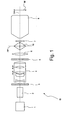
- FIG. 1 shows a lighting device designated overall by IS a microlithographic projection exposure apparatus in a greatly simplified and not to scale meridional section.
- the lighting device IS comprises a laser serving as a light source 1, which generates a collimated light beam, a Beam shaping device 2, a first optical raster element 3, the first time the divergence of the light beam increased, a zoom axicon lens 4 for setting different Types of lighting and a second optical Raster element 5.
- a condenser lens 6 In the beam path behind it is a condenser lens 6, a light mixer 10, through it a field plane FP extends, and an adjustable masking device 7 arranged with which the geometry set the reticle passing through the light field leaves.
- the illumination device IS further comprises a masking objective 8, in whose object plane the masking device 7 and arranged in the image plane, a mask M. is.
- the masking device 7 is thus of the masking lens 8 is focused on the mask M and thus ensures a sharp boundary of the light field.
- the light mixer 10 is in perspective shown.
- the light mixer 10 includes a first wedge prism 12 and a second wedge prism 14, whose base each in the shape of a right-angled isosceles Triangle has.
- the two wedge prisms 12, 14 are on their hypotenuse surfaces via a beam splitter layer 16 connected with each other.
- the light mixer 10 has thereby overall the shape of a square with square base.
- the two wedge prisms 12, 14 each consist of one Material that is transparent to the light used.
- the beam splitter layer 16 comprises a plurality of thin dielectric Single layers whose refractive indices are known per se Way are coordinated so that the Beam splitter layer 16 approximately equally incident on Light transmits and reflects.
- the light mixer 10 acts due to its cuboid shape for the out of the light bundles 22, 24 existing light distribution as a whole no-frictional plane-parallel plate.
- the light mixer 10 therefore generates certain aberrations such as spherical aberration and coma, but these can be Aberration comparatively easy by itself Known measures in the design of the lighting device Compensate for IS.
- the input side catheter surfaces 26, 28 opposite therefore, two light beams 23, 25 exit the light mixer 10 under equal angles in terms of magnitude to the optical axis OA.
- FIG. 3 shows a sectional view of the light mixer 10 along the line III-III.
- the cutting plane thus runs perpendicular to the beam splitter layer 16 and contains the optical axis OA.
- the indicated by a solid line light beam 30th penetrates the beam splitter layer at about 50% of its intensity 16 and occurs after breaking at a rear Kathetenseite 34 of the first wedge prism 12 as a partial beam 30 'at the angle ⁇ from the light mixer 10th out.
- the light mixer works for the transmitted partial beam 10 thus, as already mentioned, as plane-parallel Plate.
- the light beam 30 is on the beam splitter layer 16 is reflected and is a partial beam 30 "on a rearward catheter surface 36 of the first Wedge prism 12 steered. After breaking at this Boundary surface, the reflected partial beam 30 "leaves the Light mixer 10 at the angle ⁇ '.
- the second incident light beam 32 causes the light mixer 10 overall a symmetrization of the radiation distribution. You can convince yourself of that, for example assumes that the second incident light beam 32 a lower intensity than the first incident Light beam 30 has. Since the from the division at the Beam splitter layer 16 resulting partial beams respectively have the same intensity, each superimposed a reflective and a transmitted partial light beam to an exiting light beam, its intensity equal to half the sum of the intensities is the two incident light beams 30, 32 respectively to have. For a beam splitter layer 16, its reflectivity exactly equal to the transmissivity is, is the symmetrization of the intensities of the incident Light rays 30, 32 thus complete, namely regardless of the size of the difference of these intensities.
- the symmetrization becomes the weaker, the stronger the reflectivity the beam splitter layer 16 of their transmissivity differs. However, it also shows that at smaller differences between the intensities of the incident Light rays 30, 32 even then a good symmetrization is achieved when the reflectivity of the Beam splitter layer 16 only approximately with their transmissivity matches.
- the beam splitter layer 16 also be carried out polarization selective.
- polarization-selective beam splitter layers are also known in the art, so that there is none requires more detailed explanations.
- FIGS. 4 to 6 show a light mixer 210 according to FIG a second embodiment of the invention in one perspective view, one of the figure 2 corresponding Sectional view or a section along the Line VI-VI. Same or corresponding parts are denoted by 200 increased reference numerals.
- the light mixer 210 differs i.a. thereby, that this not only a beam splitter layer, but two beam splitter layers 216a, 216b included in the Figure 4 highlighted by different density punctures are.
- the two beam splitter layers 216a, 216b are also flat here and have the property that the reflectivity is approximately equal to the transmissivity is.
- the two beam splitter layers 216a, 216b are arranged perpendicular to each other, wherein the optical Axis OA through the intersection of the beam splitter layers 216a, 216b runs.
- the basic form of the light mixer 210 may be straight through two Circular cones 38, 40 are described, their base surfaces adjoin one another. Each of the two circular cones 38, 40 is in four unspecified cone segments divided, between which the two beam splitter layers 216a, 216b.
- the one under one Angle to the optical axis OA on the light mixer 210 incident light beam B is first on a lateral surface Broken the cone 38 and hits the here exemplified arrangement initially on the second beam splitter layer 216b.
- the second Beam splitter layer 216b incident light beam B is at the second beam splitter layer 216b into a continuous one Partial beam BT and a reflected partial beam Split BR.
- the two partial beams BT, BR meet now each on the first beam splitter layer 216a and there each again in two sub-beams BTT, BTR and BRT, BRR split.
- a total of four partial beams show, namely a partial beam BTT, which was not reflected at all (solid line), two partial beams BTR and BRT, the each time when passing through the light mixer 210 were reflected (dashed), and a fourth Beam BRR twice when passing through the Light mixer 210 was reflected (dotted line).
- FIG. 5 shows a section through the light mixer 210, wherein the sectional plane through the direction of the incident Beam B and the solder on the second Beam splitter surface 216b is clamped.
- Partial beam BRT form a similar configuration like the beams 30, 30 'and 30 "shown in FIG are.
- the partial beams BTT and BRT have, unlike the beams 30 ', 30 "in the light mixer 10, only a quarter of the intensity of the incident Ray B.
- the light mixer 210 has a similar symmetrizing effect like the light mixer 10, but with the difference that the effect is rotationally symmetric overall.
- the Light mixer 210 is due to this rotational symmetry particularly suitable, rotationally symmetric light distributions to symmetrize.
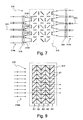
- FIG. 7 shows a total of 310 Light mixer according to another aspect of the invention.
- An incident light beam 314a that is symmetrical to a Input-side optical axis OA1 on the light mixer 310 falls and does not have to be collapsed, passes through first of several seamlessly adjoining Single lens existing lenticular 316.
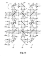
- the Lens grid 316 divides the incident light beam 314a into a plurality of mutually separate sub-bundles 3181, 3182, 3183 and 3184 that fall on a mixing unit 312, which enlarges with additional details in the Figure 8 is shown.
- the Beam splitters ST11, ST12, ST13 each contain one a thin plane-parallel carrier plate applied Beam splitter layer containing about 50% of the incident light transmitted and the remaining 50% reflected.
- the three beam splitters ST11, ST12 and ST13 as well as the plane mirror P12 are arranged parallel to each other, namely each at an angle of 45 ° to the input side optical Axis OA1.
- Behind the first row R1 of beam splitters is a second row R2 of beam splitters ST21, ST22, ST23 arranged at 90 ° to the beam splitters the first row R1 are tilted.
- the degree of spatial coherence is also reduced, for example, through the entrance lens 3201 divided into the mixing unit 312 incoming light beam so is that the partial beams over all output lenses 3221 to 3223 exit from the mixing unit 312.
- the Starting lenses 3221 to 3224 thus have the effect of virtual Light sources, which the spatial degree of coherence of the light.
- the coherence length is for example about 10 mm.
- the light beam impinging on the light mixer 310 314a is not collimated, but one nonzero Has divergence. Therefore, it is necessary in addition to the input lenses 3201 to 3204 and the output lenses 3221 to 3224 further designated L lenses within the mixing unit 312 such that the optical aperture is transported through the mixing unit 312 can be.
- L lenses within the mixing unit 312 such that the optical aperture is transported through the mixing unit 312 can be.
- the illustrated embodiment is therefore between every two adjacent beam splitters ST or plane mirrors P each have a converging lens L, their focal length f the distance between each one Beam splitter or PlanLitemitte and the lens L corresponds.
- the beam splitters ST can in this case seamlessly together be added, resulting in the in the figure 9 shown arrangement of a mixing unit 312 'results. Because the Beam splitter of the first row R1 'for an impact of the collimated light beam 314a 'a continuous surface offers, in this arrangement, the beam splitter ST also no input-side and output-side lenticular grids 316 or 324 required. The one shown in FIG Arrangement of the beam splitters ST also allows to do this as a small beam splitter cube, the seamless adjoin one another. This very compact construction allows a lot of rows R1 'to R5' in a small space of beam splitters ST to arrange.
- the light mixer 310 or 310 'to additional levels of beam splitters can be added, staggered in the direction perpendicular to the paper plane direction arranged one behind the other. Should a homogenization also in the direction perpendicular to the paper plane can be generated, this can for example be achieved be that from the light mixer 310 or 310 ' emerging light beams 314b a second light mixer which is the same as the light mixer 310 or 310 'is executed, but 90 ° about the optical axis is arranged rotated.
- Blender 310 does not require the use of collimated light assuming, is also an arrangement of the light mixer 310 behind such optical elements of the lighting device possible, which for the first time a radiation divergence have introduced. This is why, for example, also the field plane FP shown in FIG.
- the light mixer 310 ' can only in parallel Beam path can be used. Suitable as a position a place before the first optical raster element 3, this is the divergence of the projection light beam for the first time increased, and preferably before the beam shaping device 2, e.g. immediately behind the laser 1.
- the Light mixer 310 'then homogenizes that from the laser 1 produced projection light, before this on subsequent meets optical elements.
Landscapes
- Physics & Mathematics (AREA)
- General Physics & Mathematics (AREA)
- Optics & Photonics (AREA)
- Exposure And Positioning Against Photoresist Photosensitive Materials (AREA)
- Optical Elements Other Than Lenses (AREA)
Abstract
Description
- Figur 1
- eine schematische und nicht maßstäbliche Darstellung einer Beleuchtungseinrichtung einer mikrolithographischen Projektionsbelichtungsanlage in einem Meridionalschnitt;
- Figur 2
- eine perspektivische Darstellung eines in der Beleuchtungseinrichtung der Figur 1 gezeigten Lichtmischers gemäß einem ersten Ausführungsbeispiel;
- Figur 3
- einen Schnitt durch den in der Figur 2 gezeigten Lichtmischer entlang der Linie III-III;
- Figur 4
- eine perspektivische Darstellung eines für die Beleuchtungseinrichtung der Figur 1 geeigneten Lichtmischers gemäß einem zweiten Ausführungsbeispiel;
- Figur 5
- einen Schnitt durch den in der Figur 4 gezeigten Lichtmischer;
- Figur 6
- einen Schnitt durch den in den Figuren 4 und 5 gezeigten Lichtmischer entlang der Linie VI-VI;
- Figur 7
- einen Meridionalschnitt durch einen Lichtmischer gemäß einem dritten Ausführungsbeispiel mit mehreren Reihen von Strahlteilern;
- Figur 8
- eine vergrößerte Darstellung in dem Lichtmischer aus der Figur 7 enthaltenen Mischeinheit;
- Figur 9
- einen vereinfachten Meridionalschnitt durch einen Lichtmischer gemäß einem vierten Ausführungsbeispiel mit mehreren Reihen von Strahlteilerwürfeln.
Claims (31)
- Beleuchtungseinrichtung einer mikrolithographischen Projektionsbelichtungsanlage mit einem Lichtmischer (10; 210) zur Homogenisierung von Strahlungsverteilungen, der mindestens eine ebene Strahlteilerschicht (16; 216a, 216b) umfaßt, die zwischen zwei transparenten Teilelementen (12, 14) parallel zu einer optischen Achse (OA) der Beleuchtungseinrichtung (IS) angeordnet ist.
- Beleuchtungseinrichtung nach Anspruch 1, dadurch gekennzeichnet, daß das Transmissionsvermögen der mindestens einen Strahlteilerschicht (16; 216a, 216b) zumindest annähernd gleich deren Reflexionsvermögen ist.
- Beleuchtungseinrichtung nach Anspruch 1 oder 2, dadurch gekennzeichnet, daß die mindestens eine Strahlteilerschicht (16; 216a, 216b) die optische Achse (OA) enthält.
- Beleuchtungseinrichtung nach Anspruch 4, dadurch gekennzeichnet, daß zwei Strahlteilerschichten (216a, 216b) zwischen sich einen Winkel aufspannen.
- Beleuchtungseinrichtung nach Anspruch 4, dadurch gekennzeichnet, daß der Winkel 90° beträgt.
- Beleuchtungseinrichtung nach Anspruch 4 oder 5, dadurch gekennzeichnet, daß der Lichtmischer m, m = 3, 4, ..., Strahlteilerschichten enthält, wobei zwei benachbarte Strahlteilerschichten einen Winkel von 360°/m aufspannen.
- Beleuchtungseinrichtung nach einem der vorhergehenden Ansprüche, dadurch gekennzeichnet, daß die Teilelemente (12, 14) alle die gleiche geometrische Grundform haben.
- Lichtmischer nach Anspruch 7, dadurch gekennzeichnet, daß die Teilelemente (12, 14) Prismen sind.
- Lichtmischer nach Anspruch 8, dadurch gekennzeichnet, daß der Lichtmischer (10) zumindest im wesentlichen die Form eines Quaders hat, wobei die optische Achse (OA) durch eine Kante (18, 20) des Quaders verläuft.
- Beleuchtungseinrichtung nach Anspruch 9, dadurch gekennzeichnet, daß die optische Achse (OA) durch eine Ecke des Quaders verläuft.
- Beleuchtungseinrichtung nach einem der Ansprüche 8 bis 10, dadurch gekennzeichnet, daß der Lichtmischer zumindest im wesentlichen die Form eines Würfels hat.
- Beleuchtungseinrichtung nach einem der Ansprüche 1 bis 7, dadurch gekennzeichnet, daß der Lichtmischer (210) eine Grundform hat, die durch zwei an ihren Basisflächen aneinander angrenzende gerade Kreiskegel (38, 40) beschreibbar ist.
- Beleuchtungseinrichtung nach Anspruch 12, dadurch gekennzeichnet, daß die Teilelemente die Form von Kegelsegmenten haben.
- Beleuchtungseinrichtung nach einem der Ansprüche 1 bis 7, dadurch gekennzeichnet, daß der Lichtmischer zumindest im wesentlichen die Form eines Rhombus hat.
- Beleuchtungseinrichtung nach einem der vorhergehenden Ansprüche, dadurch gekennzeichnet, daß die mindestens eine Strahlteilerschicht (16, 216a, 216b) mindestens zwei Einzelschichten mit unterschiedlichen Brechzahlen umfaßt.
- Beleuchtungseinrichtung nach einem der vorhergehenden Ansprüche, dadurch gekennzeichnet, daß die mindestens eine Strahlteilerschicht eine polarisationsselektive Strahlteilerschicht ist.
- Beleuchtungseinrichtung nach Anspruch 16, dadurch gekennzeichnet, daß das Reflexionsvermögen für s-polarisiertes Licht sich um einen Faktor 2, vorzugsweise um mehr als einen Faktor 10, von dem Reflexionsvermögen für p-polarisiertes Licht unterscheidet.
- Beleuchtungseinrichtung nach Anspruch 17, dadurch gekennzeichnet, daß der Lichtmischer (10) in einer Feldebene (FP) der Beleuchtungseinrichtung (IS) angeordnet ist.
- Beleuchtungseinrichtung nach Anspruch 18, dadurch gekennzeichnet, daß die Feldebene (FP) durch eine Symmetrieebene des Lichtmischers (10) verläuft.
- Beleuchtungseinrichtung einer mikrolithographischen Projektionsbelichtungsanlage mit einem Lichtmischer (310; 310') zur Homogenisierung von Strahlungsverteilungen, der mindestens eine Reihe (R1 bis R3; R1' bis R5') von Strahlteilern (ST11, ST12, ST13, ST21, ST22, ST23, ST31, ST32, ST33) umfaßt, wobei in der mindestens einen Reihe die Strahlteilera) parallel zueinander,b) in einem Neigungswinkel zu einer eingangsseitigen optischen Achse (OA1) der Beleuchtungseinrichtung (IS) undc) in einer zu der eingangsseitigen optischen Achse (OA1) senkrechten Richtung versetzt hintereinander angeordnet sind.
- Beleuchtungseinrichtung nach Anspruch 20, dadurch gekennzeichnet, daß der Neigungswinkel der mindestens einen Reihe (R1 bis R3; R1' bis R5') 45° beträgt.
- Beleuchtungseinrichtung nach Anspruch 20 oder 21, dadurch gekennzeichnet, daß sich in Reihen (R1 bis R3; R1' bis R5'), die entlang der eingangsseitigen optischen Achse OA aufeinander folgen, die Neigungswinkel jeweils betragsmäßig um 90° voneinander unterscheiden.
- Beleuchtungseinrichtung nach einem der Ansprüche 20 bis 22, dadurch gekennzeichnet, daß die Strahlteiler (ST11, ST12, ST13, ST21, ST22, ST23, ST31, ST32, ST33) so angeordnet sind, daß jeder in den Lichtmischer eintretende Lichtstrahl bei seinem Durchtritt durch den Lichtmischer (310; 310') auf mindestens zwei Strahlteiler trifft.
- Beleuchtungseinrichtung nach einem der Ansprüche 20 bis 23, dadurch gekennzeichnet, daß zwischen jeweils zwei benachbarten Strahlteilern (ST11, ST12, ST13, ST21, ST22, ST23, ST31, ST32, ST33) ein optisches Element (L) mit positiver Brechkraft angeordnet ist.
- Beleuchtungseinrichtung nach einem der Ansprüche 20 bis 24, gekennzeichnet durch eine eingangsseitige Abbildungseinheit (316), welche ein zusammenhängendes einfallendes Lichtbündel (314a) in Teillichtbündel (3181, 3182, 3183, 3184) aufteilt, die auf eingangsseitige Strahlteiler (ST11, ST12, ST13) gerichtet werden.
- Beleuchtungseinrichtung nach einem der Ansprüche 20 bis 25, gekennzeichnet durch eine ausgangsseitige Abbildungseinheit (324), welche von ausgangsseitigen Strahlteilern (ST31, ST32, ST33) ausgehende Teillichtbündel zu einem zusammenhängenden Lichtbündel (314b) zusammenführt.
- Beleuchtungseinrichtung nach einem der Ansprüche 20 bis 26, gekennzeichnet durch eine Umlenkeinrichtung (P11, P21, P21, P22, P32), die Licht, das einen äußersten Strahlteiler (ST11, ST34, ST31) einer Reihe (R1, R2, R3) durchtritt, auf eine nachfolgende Reihe richtet.
- Beleuchtungseinrichtung nach Anspruch 27, dadurch gekennzeichnet, daß die Umlenkeinrichtung mindestens einen Spiegel (P11, P21, P21, P22, P32) umfaßt.
- Beleuchtungseinrichtung nach einem der Ansprüche 20 bis 29, dadurch gekennzeichnet, daß der Lichtmischer (310; 310') im parallelen Strahlengang angeordnet ist.
- Beleuchtungseinrichtung nach Anspruch 29, dadurch gekennzeichnet, daß der Lichtmischer (310') vor einem optischen Element (3) der Beleuchtungseinrichtung (IS) angeordnet ist, das die Divergenz der Strahlungsverteilung erstmalig erhöht.
- Projektionsbelichtungsanlage mit einer Beleuchtungseinrichtung (IS) nach einem der vorhergehenden Ansprüche.
Applications Claiming Priority (2)
| Application Number | Priority Date | Filing Date | Title |
|---|---|---|---|
| US57852104P | 2004-06-10 | 2004-06-10 | |
| US578521P | 2004-06-10 |
Publications (2)
| Publication Number | Publication Date |
|---|---|
| EP1605311A2 true EP1605311A2 (de) | 2005-12-14 |
| EP1605311A3 EP1605311A3 (de) | 2007-03-14 |
Family
ID=34936555
Family Applications (1)
| Application Number | Title | Priority Date | Filing Date |
|---|---|---|---|
| EP05010584A Withdrawn EP1605311A3 (de) | 2004-06-10 | 2005-05-17 | Beleuchtungseinrichtung mit einem Lichtmischer zur Homogenisierung von Strahlungsverteilungen |
Country Status (2)
| Country | Link |
|---|---|
| US (1) | US20050280821A1 (de) |
| EP (1) | EP1605311A3 (de) |
Families Citing this family (2)
| Publication number | Priority date | Publication date | Assignee | Title |
|---|---|---|---|---|
| US20080013182A1 (en) * | 2006-07-17 | 2008-01-17 | Joerg Ferber | Two-stage laser-beam homogenizer |
| US7615722B2 (en) * | 2006-07-17 | 2009-11-10 | Coherent, Inc. | Amorphous silicon crystallization using combined beams from optically pumped semiconductor lasers |
Family Cites Families (8)
| Publication number | Priority date | Publication date | Assignee | Title |
|---|---|---|---|---|
| US2882784A (en) * | 1955-10-24 | 1959-04-21 | Dominic S Toffolo | Conical refractor |
| US2881654A (en) * | 1955-10-24 | 1959-04-14 | Dominic S Toffolo | Biconical refractor |
| US3547526A (en) * | 1967-10-26 | 1970-12-15 | Kollsman Instr Corp | Optical beam cross-section converter |
| US5751480A (en) * | 1991-04-09 | 1998-05-12 | Canon Kabushiki Kaisha | Plate-like polarizing element, a polarizing conversion unit provided with the element, and a projector provided with the unit |
| US6285443B1 (en) * | 1993-12-13 | 2001-09-04 | Carl-Zeiss-Stiftung | Illuminating arrangement for a projection microlithographic apparatus |
| US6191887B1 (en) * | 1999-01-20 | 2001-02-20 | Tropel Corporation | Laser illumination with speckle reduction |
| US6347176B1 (en) * | 2000-06-15 | 2002-02-12 | Ultratech Stepper, Inc. | Acousto-optical light tunnel apparatus and method |
| DE10065198A1 (de) * | 2000-12-20 | 2002-07-11 | Zeiss Carl | Lichtintegrator für eine Beleuchtungseinrichtung |
-
2005
- 2005-05-17 EP EP05010584A patent/EP1605311A3/de not_active Withdrawn
- 2005-06-08 US US11/147,931 patent/US20050280821A1/en not_active Abandoned
Also Published As
| Publication number | Publication date |
|---|---|
| US20050280821A1 (en) | 2005-12-22 |
| EP1605311A3 (de) | 2007-03-14 |
Similar Documents
| Publication | Publication Date | Title |
|---|---|---|
| DE112005003207B4 (de) | Optisches Beleuchtungssystem zum Erzeugen eines Linienstrahls | |
| EP1343051B1 (de) | Mikrolithographie-Projektionsbelichtungsanlage mit radial-polarisations-drehender optischer Anordnung | |
| WO2005017620A2 (de) | Beleuchtungseinrichtung sowie polarisator für eine mikrolithographische projektionsbelichtungsanlage | |
| EP0710369A1 (de) | Höchstaperturiges katadioptrisches reduktionsobjektiv für die mikrolithographie | |
| DE102008054582A1 (de) | Mikrolithographische Projektionsbelichtungsanlage | |
| DE10127227A1 (de) | Katadioptrisches Reduktionsobjektiv | |
| DE10344010A1 (de) | Wabenkondensor und Beleuchtungssystem damit | |
| DE102012213515A1 (de) | Verfahren zum Betreiben einer mikrolithographischen Projektionsbelichtungsanlage | |
| DE10040898A1 (de) | Beleuchtungssystem für die Mikrolithographie | |
| DE10206061A1 (de) | Polarisationsoptimiertes Beleuchtungssystem | |
| DE102009009366A1 (de) | Vorrichtung zur Homogenisierung von Laserstrahlung | |
| DE112011102900B4 (de) | Abbildungssystem | |
| EP1217450A2 (de) | Lichtintegrator für eine Beleuchtungseinrichtung | |
| DE102007023411A1 (de) | Optisches Element, Beleuchtungsoptik für die Mikrolithographie mit mindestens einem derartigen optischen Element sowie Beleuchtungssystem mit einer derartigen Beleuchtungsoptik | |
| DE10201315A1 (de) | Kohärenzminderer | |
| DE10132988B4 (de) | Projektionsbelichtungsanlage | |
| DE19627568A1 (de) | Anordnung und Verfahren zur konfokalen Mikroskopie | |
| DE10215162A1 (de) | Strahlteilervorrichtung bzw. Laserrastermikroskop | |
| DE10322375A1 (de) | Polarisationsoptimiertes Axiconsystem und Beleuchtungssystem mit einem solchen Axiconsystem | |
| EP3737999A1 (de) | Pupillenfacettenspiegel, beleuchtungsoptik und optisches system für eine projektionsbelichtungsanlage | |
| DE102015209175A1 (de) | Pupillenfacettenspiegel | |
| DE102007055443A1 (de) | Stabmischsystem und Verfahren hierzu zur pupillenerhaltenden Feldhomogenisierung in einem Beleichtungssystem | |
| DE102011076436B4 (de) | Beleuchtungsoptik für die Projektionslithografie | |
| DE102009045217B3 (de) | Katadioptrisches Projektionsobjektiv | |
| DE19856575A1 (de) | Projektions-Mikrolithographiegerät |
Legal Events
| Date | Code | Title | Description |
|---|---|---|---|
| PUAI | Public reference made under article 153(3) epc to a published international application that has entered the european phase |
Free format text: ORIGINAL CODE: 0009012 |
|
| AK | Designated contracting states |
Kind code of ref document: A2 Designated state(s): AT BE BG CH CY CZ DE DK EE ES FI FR GB GR HU IE IS IT LI LT LU MC NL PL PT RO SE SI SK TR |
|
| AX | Request for extension of the european patent |
Extension state: AL BA HR LV MK YU |
|
| PUAL | Search report despatched |
Free format text: ORIGINAL CODE: 0009013 |
|
| AK | Designated contracting states |
Kind code of ref document: A3 Designated state(s): AT BE BG CH CY CZ DE DK EE ES FI FR GB GR HU IE IS IT LI LT LU MC NL PL PT RO SE SI SK TR |
|
| AX | Request for extension of the european patent |
Extension state: AL BA HR LV MK YU |
|
| RAP1 | Party data changed (applicant data changed or rights of an application transferred) |
Owner name: CARL ZEISS SMT AG |
|
| AKX | Designation fees paid | ||
| STAA | Information on the status of an ep patent application or granted ep patent |
Free format text: STATUS: THE APPLICATION IS DEEMED TO BE WITHDRAWN |
|
| 18D | Application deemed to be withdrawn |
Effective date: 20070915 |
|
| REG | Reference to a national code |
Ref country code: DE Ref legal event code: 8566 |