EP1605282A1 - Flüssiges Salz enthaltende optische Vorrichtung - Google Patents
Flüssiges Salz enthaltende optische Vorrichtung Download PDFInfo
- Publication number
- EP1605282A1 EP1605282A1 EP20050104741 EP05104741A EP1605282A1 EP 1605282 A1 EP1605282 A1 EP 1605282A1 EP 20050104741 EP20050104741 EP 20050104741 EP 05104741 A EP05104741 A EP 05104741A EP 1605282 A1 EP1605282 A1 EP 1605282A1
- Authority
- EP
- European Patent Office
- Prior art keywords
- salt
- optical
- medium
- optical component
- temperature
- Prior art date
- Legal status (The legal status is an assumption and is not a legal conclusion. Google has not performed a legal analysis and makes no representation as to the accuracy of the status listed.)
- Withdrawn
Links
- 230000003287 optical effect Effects 0.000 title claims abstract description 85
- 150000003839 salts Chemical class 0.000 title claims abstract description 64
- 239000007788 liquid Substances 0.000 title claims abstract description 26
- 239000000835 fiber Substances 0.000 claims abstract description 16
- 239000004038 photonic crystal Substances 0.000 claims abstract description 6
- 238000003860 storage Methods 0.000 claims abstract description 4
- 239000000203 mixture Substances 0.000 claims description 36
- 230000004044 response Effects 0.000 claims description 16
- 150000001450 anions Chemical class 0.000 claims description 15
- 150000001768 cations Chemical class 0.000 claims description 12
- 238000007654 immersion Methods 0.000 claims description 10
- 125000001931 aliphatic group Chemical group 0.000 claims description 6
- 229910020366 ClO 4 Inorganic materials 0.000 claims description 4
- 125000003118 aryl group Chemical group 0.000 claims description 4
- 125000000484 butyl group Chemical group [H]C([*])([H])C([H])([H])C([H])([H])C([H])([H])[H] 0.000 claims description 4
- 125000002496 methyl group Chemical group [H]C([H])([H])* 0.000 claims description 4
- JUJWROOIHBZHMG-UHFFFAOYSA-O pyridinium Chemical compound C1=CC=[NH+]C=C1 JUJWROOIHBZHMG-UHFFFAOYSA-O 0.000 claims description 4
- ITMCEJHCFYSIIV-UHFFFAOYSA-M triflate Chemical compound [O-]S(=O)(=O)C(F)(F)F ITMCEJHCFYSIIV-UHFFFAOYSA-M 0.000 claims description 4
- QGZKDVFQNNGYKY-UHFFFAOYSA-O Ammonium Chemical compound [NH4+] QGZKDVFQNNGYKY-UHFFFAOYSA-O 0.000 claims description 3
- 125000001495 ethyl group Chemical group [H]C([H])([H])C([H])([H])* 0.000 claims description 3
- XYFCBTPGUUZFHI-UHFFFAOYSA-O phosphonium Chemical compound [PH4+] XYFCBTPGUUZFHI-UHFFFAOYSA-O 0.000 claims description 3
- RWSOTUBLDIXVET-UHFFFAOYSA-O sulfonium Chemical compound [SH3+] RWSOTUBLDIXVET-UHFFFAOYSA-O 0.000 claims description 3
- ZXMGHDIOOHOAAE-UHFFFAOYSA-N 1,1,1-trifluoro-n-(trifluoromethylsulfonyl)methanesulfonamide Chemical compound FC(F)(F)S(=O)(=O)NS(=O)(=O)C(F)(F)F ZXMGHDIOOHOAAE-UHFFFAOYSA-N 0.000 claims description 2
- WHXSMMKQMYFTQS-UHFFFAOYSA-N Lithium Chemical compound [Li] WHXSMMKQMYFTQS-UHFFFAOYSA-N 0.000 claims description 2
- DTQVDTLACAAQTR-UHFFFAOYSA-M Trifluoroacetate Chemical compound [O-]C(=O)C(F)(F)F DTQVDTLACAAQTR-UHFFFAOYSA-M 0.000 claims description 2
- QAOWNCQODCNURD-UHFFFAOYSA-M hydrogensulfate Chemical compound OS([O-])(=O)=O QAOWNCQODCNURD-UHFFFAOYSA-M 0.000 claims description 2
- 229910052744 lithium Inorganic materials 0.000 claims description 2
- VLTRZXGMWDSKGL-UHFFFAOYSA-M perchlorate Inorganic materials [O-]Cl(=O)(=O)=O VLTRZXGMWDSKGL-UHFFFAOYSA-M 0.000 claims description 2
- YPJUNDFVDDCYIH-UHFFFAOYSA-N perfluorobutyric acid Chemical compound OC(=O)C(F)(F)C(F)(F)C(F)(F)F YPJUNDFVDDCYIH-UHFFFAOYSA-N 0.000 claims description 2
- 125000001436 propyl group Chemical group [H]C([*])([H])C([H])([H])C([H])([H])[H] 0.000 claims description 2
- 229910017008 AsF 6 Inorganic materials 0.000 claims 2
- RAXXELZNTBOGNW-UHFFFAOYSA-O Imidazolium Chemical compound C1=C[NH+]=CN1 RAXXELZNTBOGNW-UHFFFAOYSA-O 0.000 claims 1
- XMBWDFGMSWQBCA-UHFFFAOYSA-N hydrogen iodide Chemical compound I XMBWDFGMSWQBCA-UHFFFAOYSA-N 0.000 claims 1
- IQQRAVYLUAZUGX-UHFFFAOYSA-N 1-butyl-3-methylimidazolium Chemical compound CCCCN1C=C[N+](C)=C1 IQQRAVYLUAZUGX-UHFFFAOYSA-N 0.000 description 14
- 230000003595 spectral effect Effects 0.000 description 11
- 230000005540 biological transmission Effects 0.000 description 8
- -1 hexafluorophosphate Chemical compound 0.000 description 6
- 238000006073 displacement reaction Methods 0.000 description 5
- 230000008901 benefit Effects 0.000 description 4
- 230000004048 modification Effects 0.000 description 4
- 238000012986 modification Methods 0.000 description 4
- 239000007787 solid Substances 0.000 description 4
- 230000032683 aging Effects 0.000 description 3
- 239000000470 constituent Substances 0.000 description 3
- 230000008020 evaporation Effects 0.000 description 3
- 238000001704 evaporation Methods 0.000 description 3
- 238000004519 manufacturing process Methods 0.000 description 3
- 239000002904 solvent Substances 0.000 description 3
- 238000007792 addition Methods 0.000 description 2
- 230000003321 amplification Effects 0.000 description 2
- 230000008859 change Effects 0.000 description 2
- 238000005253 cladding Methods 0.000 description 2
- 150000001875 compounds Chemical class 0.000 description 2
- 230000008878 coupling Effects 0.000 description 2
- 238000010168 coupling process Methods 0.000 description 2
- 238000005859 coupling reaction Methods 0.000 description 2
- 238000002425 crystallisation Methods 0.000 description 2
- 230000008025 crystallization Effects 0.000 description 2
- 238000003780 insertion Methods 0.000 description 2
- 230000037431 insertion Effects 0.000 description 2
- 239000002608 ionic liquid Substances 0.000 description 2
- 238000002156 mixing Methods 0.000 description 2
- 238000003199 nucleic acid amplification method Methods 0.000 description 2
- 239000013307 optical fiber Substances 0.000 description 2
- 238000010521 absorption reaction Methods 0.000 description 1
- 230000009471 action Effects 0.000 description 1
- 230000006978 adaptation Effects 0.000 description 1
- 238000009835 boiling Methods 0.000 description 1
- 125000002091 cationic group Chemical group 0.000 description 1
- 238000004140 cleaning Methods 0.000 description 1
- 239000013078 crystal Substances 0.000 description 1
- 230000007423 decrease Effects 0.000 description 1
- 230000003247 decreasing effect Effects 0.000 description 1
- 238000010586 diagram Methods 0.000 description 1
- 239000012636 effector Substances 0.000 description 1
- 238000001914 filtration Methods 0.000 description 1
- 125000001153 fluoro group Chemical group F* 0.000 description 1
- 238000009432 framing Methods 0.000 description 1
- 229910052732 germanium Inorganic materials 0.000 description 1
- GNPVGFCGXDBREM-UHFFFAOYSA-N germanium atom Chemical compound [Ge] GNPVGFCGXDBREM-UHFFFAOYSA-N 0.000 description 1
- PCHJSUWPFVWCPO-UHFFFAOYSA-N gold Chemical compound [Au] PCHJSUWPFVWCPO-UHFFFAOYSA-N 0.000 description 1
- 239000010931 gold Substances 0.000 description 1
- 229910052737 gold Inorganic materials 0.000 description 1
- 150000004693 imidazolium salts Chemical class 0.000 description 1
- 208000003173 lipoprotein glomerulopathy Diseases 0.000 description 1
- 239000007791 liquid phase Substances 0.000 description 1
- 238000000034 method Methods 0.000 description 1
- 239000012071 phase Substances 0.000 description 1
- 230000010287 polarization Effects 0.000 description 1
- 230000002441 reversible effect Effects 0.000 description 1
- 239000011829 room temperature ionic liquid solvent Substances 0.000 description 1
- 239000011833 salt mixture Substances 0.000 description 1
- 239000007790 solid phase Substances 0.000 description 1
- 238000007711 solidification Methods 0.000 description 1
- 230000008023 solidification Effects 0.000 description 1
- 239000011877 solvent mixture Substances 0.000 description 1
- 238000001228 spectrum Methods 0.000 description 1
- 230000001988 toxicity Effects 0.000 description 1
- 231100000419 toxicity Toxicity 0.000 description 1
- 230000007704 transition Effects 0.000 description 1
- 238000000411 transmission spectrum Methods 0.000 description 1
- XLYOFNOQVPJJNP-UHFFFAOYSA-N water Substances O XLYOFNOQVPJJNP-UHFFFAOYSA-N 0.000 description 1
- 230000004584 weight gain Effects 0.000 description 1
- 235000019786 weight gain Nutrition 0.000 description 1
Images


Classifications
-
- G—PHYSICS
- G02—OPTICS
- G02B—OPTICAL ELEMENTS, SYSTEMS OR APPARATUS
- G02B1/00—Optical elements characterised by the material of which they are made; Optical coatings for optical elements
- G02B1/06—Optical elements characterised by the material of which they are made; Optical coatings for optical elements made of fluids in transparent cells
-
- G—PHYSICS
- G02—OPTICS
- G02B—OPTICAL ELEMENTS, SYSTEMS OR APPARATUS
- G02B1/00—Optical elements characterised by the material of which they are made; Optical coatings for optical elements
- G02B1/02—Optical elements characterised by the material of which they are made; Optical coatings for optical elements made of crystals, e.g. rock-salt, semi-conductors
-
- G—PHYSICS
- G02—OPTICS
- G02B—OPTICAL ELEMENTS, SYSTEMS OR APPARATUS
- G02B6/00—Light guides; Structural details of arrangements comprising light guides and other optical elements, e.g. couplings
- G02B6/02—Optical fibres with cladding with or without a coating
- G02B6/02295—Microstructured optical fibre
- G02B6/02314—Plurality of longitudinal structures extending along optical fibre axis, e.g. holes
- G02B6/0239—Comprising means for varying the guiding properties, e.g. tuning means
Definitions
- the present invention relates to the field of optical devices comprising an optical component and an optical medium of different optical indices, in which the optical properties of the optical component depend at least partially from this optical medium.
- the optical components can be of volume or integrated into waveguides such as optical fibers or planar waveguides. These waveguides, fibered or planar, can be crystal photonics. These optical components can be, for example, networks of Bragg, whose features are straight or angled, with short or long steps, couplers, Mach-Zehnder interferometers based on couplers, fibers tapers, or sections of specific fiber such as sections of fiber with photonic crystal.
- the invention is described hereinafter more specifically in the case of optical devices including, as optical components, Bragg gratings known as "long-distance" (LPG) used to realize dynamic gain equalizers, including equalizer filters.
- LPG long-distance
- a waveguide is conventionally composed of an optical core, whose function is to transmit and possibly to amplify an optical signal, surrounded by an optical cladding, whose function is to confine the optical signal in the core.
- the refractive indices of the core n 1 and the sheath n 2 are such that n 1 > n 2 .
- the heart and the sheath form a waveguide.
- the propagation of an optical signal in a single-mode waveguide breaks down into a fundamental guided mode in the core and in secondary modes guided over a distance in the optical core-sheath assembly, called also sheath modes.
- the sheath is itself surrounded by an external medium of refractive index n 3 greater than or less than n 2 .
- the core-sheath assembly associated with the external medium again forms a waveguide.
- the heart and / or sheath of the guide can be doped to be rendered photosensitive for the registration of a Bragg network, for example with germanium (Ge).
- a Bragg network for example with germanium (Ge).
- Classically used networks for gain equalization are angled networks or inclined gratings, known as SBGs for "Slanted Bragg Grating" in English, or long-distance networks, known as LPG term for "Long Period Grading” in English.
- SBGs angled networks or inclined gratings
- LPG term long-distance networks
- ⁇ B ⁇ (n effCoeur - not effGaine ), with the step of the LPG network.
- Gain equalizing filters also known by the acronym GFF for "Gain Flattening Filter” in English, are integrated in optical devices associated with optical amplifiers regularly distributed along lines of transmission. Optical amplifiers do not generally provide a equal amplification for all wavelengths, which is particularly disturbing in the case of wavelength division multiplexing transmission (WDM, for "Wavelength Division Multiplexing” for which several signals at different wavelengths are transmitted on the same fiber and amplified by the same amplifiers. It is therefore necessary to associate with online amplifiers gain equalizer filters that remove, or at least reduce, amplification disparities of different channels of transmission of an optical system.
- WDM wavelength division multiplexing transmission
- An optical system is often scalable and it is not uncommon for the parameters of a optical component, such as a gain equalizer, are no longer adapted to the real transmission spectra. For example, such an evolution may be due to a aging, to a variation of temperature, to localized interventions on the line or additions of optical modules or optical transmission channels after installing the line. The previously set parameters of the different Optical components of the optical system then become unsuitable.
- optical component must therefore be able to be modified in order to adapt to the evolution of the other components of the system. It is therefore necessary to realize optical components that allow dynamically tune their spectral response to match changing conditions of optical systems in which they are arranged, and this on a wide spectral range and without losses.
- an LPG is particularly sensitive to changes in the external environment to the sheath of the guide on which he is registered.
- the preferred liquid media Of the optical media which may be used, the preferred liquid media.
- the solvent mixtures of the brand "CARGILLE” are unsuitable for use in the field of telecommunications.
- evaporation for example total evaporation at room temperature takes place in one week
- the liquid state of these solvents is not conserved at low and high temperatures (type transitions solidification at low temperatures and evaporation at high temperatures); gold telecommunication optical components are exposed to high temperatures may vary from -40 ° C to + 85 ° C or more.
- the present invention therefore aims to provide an optical device in which the optical properties, for example the spectral response, of the optical component can be at least partially controlled by changing the optical index of the optical medium so as to adapt the optical properties of the component optical to the evolution of the other components of the optical system.
- the optical properties for example the spectral response
- the object of the present invention is an optical device comprising a component an optical medium of different optical indices, said optical component being at least partially immersed in said medium, wherein said medium comprises at least one salt which is in the liquid state in the field of temperature of use and storage of said optical component.
- the temperature at which the salt is in a liquid state is preferably between -40 ° C and + 200 ° C.
- the operating temperature of the optical component most often varies from -10 ° C to + 70 ° C, but the optical component is likely to be stored at temperatures between -40 ° C and + 85 ° C. Salt must therefore be in the liquid state in this range and the device should not be altered by a phase change of the salt, in particular by the passage from the liquid phase to the solid phase.
- the salts according to the invention are in the liquid state over a wide range of temperature encompassing the ambient temperature, and are called RTILs for "Room Temperature Ionic Liquid” in English. They are also often called “ionic liquids” because they are compounds, or mixtures of several compounds, containing dissociated species in ionic form.
- the salts used in the present invention have the advantage of their conductivity electric high, their thermal stability, their resistance to aging. In addition in the case of salts, they are neither flammable nor volatile. Indeed their temperature boiling is non-existent as they generally degrade beyond 250 ° C without switch to the steam state.
- salts according to the present invention are stable at high temperature in the presence of moisture (for example + 85 ° C and 85% humidity relative) with regard to their refractive index (for example measured at 1500 nm and 589 nm before and after the test) and their viscosity.
- the optical medium according to the invention preferably contains a mixture of at least two salts.
- mixing is meant both the addition of two salts each in the liquid state, that a solution of at least one first liquid salt in which is dissolved and dissociates at least one second salt presenting initially in the solid state.
- the refractive index of the medium depends on the composition salt mixture. This property has the advantage of being able to obtain very precisely the desired index, especially over a range of refractive index of 1.35 to 1.52 measured at 589 nm.
- the refractive index of these salts varies with temperature, but very weakly. In some cases, this variation is too small to induce a variation in response of the optical component. This is particularly interesting in the case where the variation of the spectral response of the optical component is obtained by a modifying the immersion zone of said optical component. This is the case in the example of the LPG network described more specifically in this text, in which the adaptation of the refractive index medium is induced by a displacement of the contact area between the component and the refractive index medium.
- the variation of refractive index of optical medium with the temperature is sufficient to change the response of the optical component.
- the variation of refractive index with temperature is considered high (for example from -20 ° C to 120 ° C, ie a range of 140 ° C)
- the profile of a photonic crystal fiber can be adjusted according to the temperature of the optical medium and spectral variations in transmission on the component optics can be induced. It has been observed, in the case of tunable optics based on photonic crystal fiber, a spectral response significantly different for optical media whose refractive index varies between 1.46 and 1.48.
- the salt comprises an anion and a cation.
- the anion is preferably selected from F - fluoride, Cl - chloride, Br - bromide, I - iodide, ClO 4 - perchlorate, AlClO 4 - aluminochlorate, BF 4 - tetrafluoroborate, PF 6 hexafluorophosphate.
- the cation is preferably chosen from ammonium NH 4 + , sulphonium HSO 3 + , phosphonium PH 4 + , lithium Li + , pyridinium C 5 H 5 NH + , and imidazolium cations (C 3 H 6 N 2 X 1 X 2 ) + , ammonium cations (X 1 X 2 X 3 X 4 N 4 ) + , sulphonium cations (X 1 X 2 X 3 S) + , phosphonium cations (X 1 X 2 X 3 X 4 P) + , and the pyridinium (X 1 C 5 H 4 NX 2 ) + cations, in which X 1 , X 2 , X 3 , X 4 represent aromatic or aliphatic type groups.
- the salt is chosen from imidazolium salts.
- the cationic salt is N, N 'dialkylimidazolium of general formula: wherein R 1 and R 2 are aliphatic or aromatic groups coordinated with a counterion, such as an anion.
- R 1 and R 2 may be the same or different and contain at least one anion chosen preferably from F - , Cl - , Br - , I - , BF 4 - , PF 6 - , ClO 4 - , AlClO 4 - , CF 3 COO - , C 3 F 7 COO - , CF 3 SO 3 - , C 4 F 9 SO 3 - , (CF 3 SO 2 ) 2 N - , (CF 3 SO 2 ) 2 C - , ...
- anion chosen preferably from F - , Cl - , Br - , I - , BF 4 - , PF 6 - , ClO 4 - , AlClO 4 - , CF 3 COO - , C 3 F 7 COO - , CF 3 SO 3 - , C 4 F 9 SO 3 - , (CF 3 SO 2 ) 2 N - , (CF 3 SO 2 )
- the salt contains an anion chosen preferably from Cl - , Br - , PF 6 - , BF 4 - , (CF 3 SO 2 ) 2 N - , C 4 F 9 SO 3 - .
- the salt has a different liquefaction temperature.
- salt families that are liquid at the temperature of use and storage of the optical component.
- the physicochemical properties, and in particular the refractive index of the salt can be granted by modifying the groups R 1 and / or R 2 and / or the associated anion. It is known in particular that the insertion of fluorine atoms into the structure of the cation and the anion decreases the refractive index. On the contrary, the presence of halogenated anions such as Br - , Cl - and I - increases the refractive index of the salt. There is thus a wide choice of refractive indices by mixing at least two salts or by dissolving a solid salt in another liquid salt at the operating temperature. The reproducibility of the manufacture of such a mixture, as well as the homogeneity of the mixture obtained have been shown.
- the optical component is a network of Bragg long not, says "LPG".
- the network is preferably modification of the immersion zone.
- the optical response of the network, in contact with the medium according to the invention is substantially constant in the range of use of the optical component, between -10 ° C and + 70 ° C.
- the optical component is a section of fiber to photonic crystal.
- the response of the fiber is preferably varying the refractive index of the medium by means of a variation of temperature, preferably in a range of -20 to + 120 ° C.
- Figure 1 shows the variation of refractive index (curve 10) that can be obtained with a mixture of variable composition of two liquid salts at room temperature.
- the mixture comprises a first salt HMIM, CI and a second salt BMIM, BF 4 .
- the variation of the refractive index IR was represented as a function of the mass M of the first salt HMIM, CI expressed as a% by weight in the mixture.
- Curve 20 of FIG. 2 shows variation of the refractive index as a function of the composition of the binary mixture BMIM, BF 4 / BMIM, Br
- FIG. 3 relates to two mixtures 11 and 12 of two liquid salts for the refractive index variation as a function of temperature has been noted.
- the mixture 11 (curve 30) is composed of 48.2% by weight of a salt HMIM, CI and 51.8% by weight of a BMIM salt PF 6 marketed by the company "SOLVENT INNOVATION".
- the mixture has now a refractive index of 1.4659 for a wavelength of 589 nm at a temperature of 20 ° C, and of 1.4773 at a temperature of 0 ° C.
- the mixture 12 (curve 31) is composed of 50.5% by weight of a salt HMIM, CI and 49.5% by weight of a reference salt BMIM, BF4.
- Blend B has a clue refractive index of 1.4714 for a wavelength of 589 nm at a temperature of 20 ° C, and 1.4741 at a temperature of 0 ° C.
- the stability of the refractive index at the moist heat of the salts or mixtures of salts according to the invention was carried out at elevated temperature in presence of humidity: temperature of + 85 ° C and 85% relative humidity.
- the results are grouped in the following table 2.
- the refractive index IR is measured before and after the test at 589 nm and 20.0 ° C.
- the optical medium may for example contain a salt of N, N 'dialkylimidazolium associated with an anion BF 4 - whose R 1 and R 2 groups are respectively a methyl group and a butyl group . Its crystallization temperature is then -80 ° C.
- This salt has anti-electrostatic properties of particular interest for the intended telecommunications application.
- the crystallization temperature of the salt becomes + 15 ° C. which makes it less easy to use.
- the degree of immersion of LPG in the medium can be varied, in particular by means of a device similar to that described in the document by H. LABIDI et al. entitled “Dynamic gain control of optical amplifier using an all-fiber solution” presented at the 28 th European Conference on Optics (8-12 September 2002).
- FIG. 4 is a schematic and simplified representation of an optical fiber 40 on a portion 41 of which has been inscribed a long LPG network.
- This portion 41 may be at least partially immersed in a medium according to the invention comprising a liquid salt, and contained in a tank 42 able to move the along the fiber 40.
- the reservoir 42 is shown here in the initial position 43 in which portion 41 carrying the network is not immersed in the medium (zero displacement).
- the tank 42 can be moved in the direction shown by the arrow 44 (go), and the portion 41 is then gradually immersed in the medium contained in the reservoir 42.
- the reservoir 42 can also be moved in the opposite direction in the direction represented by the arrow 45 (return).
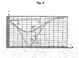
- FIG. 5 represents the spectral response of the LPG long pitch grating, of a total length of 30mm, immersed in a medium of index 1,404 at temperature ambient temperature (20 ° C).
- Curves 50 and 51 correspond to zero displacement (initial position), the response being measured respectively in the round trip.
- the curves 52 and 53 correspond to a displacement of 4mm from the position initially, the response being measured when moving to that position respectively during a trip in and out.
- the curves 54 and 55 correspond to a displacement of 8mm from the initial position, the response measured respectively on the outward and returnward directions.
Landscapes
- Physics & Mathematics (AREA)
- General Physics & Mathematics (AREA)
- Optics & Photonics (AREA)
- Chemical & Material Sciences (AREA)
- Crystallography & Structural Chemistry (AREA)
- Optical Fibers, Optical Fiber Cores, And Optical Fiber Bundles (AREA)
- Diffracting Gratings Or Hologram Optical Elements (AREA)
- Optical Modulation, Optical Deflection, Nonlinear Optics, Optical Demodulation, Optical Logic Elements (AREA)
Applications Claiming Priority (2)
| Application Number | Priority Date | Filing Date | Title |
|---|---|---|---|
| FR0451127A FR2871242B1 (fr) | 2004-06-08 | 2004-06-08 | Milieu d'indice adaptable pour composant optique |
| FR0451127 | 2004-06-08 |
Publications (1)
| Publication Number | Publication Date |
|---|---|
| EP1605282A1 true EP1605282A1 (de) | 2005-12-14 |
Family
ID=34940053
Family Applications (1)
| Application Number | Title | Priority Date | Filing Date |
|---|---|---|---|
| EP20050104741 Withdrawn EP1605282A1 (de) | 2004-06-08 | 2005-06-01 | Flüssiges Salz enthaltende optische Vorrichtung |
Country Status (4)
| Country | Link |
|---|---|
| US (1) | US7613378B2 (de) |
| EP (1) | EP1605282A1 (de) |
| CN (1) | CN1715974B (de) |
| FR (1) | FR2871242B1 (de) |
Families Citing this family (8)
| Publication number | Priority date | Publication date | Assignee | Title |
|---|---|---|---|---|
| FR2871242B1 (fr) * | 2004-06-08 | 2006-09-08 | Alcatel Sa | Milieu d'indice adaptable pour composant optique |
| EP2073000A1 (de) * | 2007-12-20 | 2009-06-24 | Nederlandse Organisatie voor toegepast- natuurwetenschappelijk onderzoek TNO | Beschichteter Wellenleiter zur optischen Erkennung |
| US9855352B2 (en) | 2014-09-13 | 2018-01-02 | Sensor Electronic Technology, Inc. | Diffusive light illuminator |
| US10197750B2 (en) | 2014-09-13 | 2019-02-05 | Sensor Electronic Technology, Inc. | AAO-based light guiding structure and fabrication thereof |
| US9703055B2 (en) | 2014-09-13 | 2017-07-11 | Sensor Electronic Technology, Inc. | AAO-based light guiding structure and fabrication thereof |
| US10025028B2 (en) | 2014-09-13 | 2018-07-17 | Sensor Electronic Technology, Inc. | Fluid-based light guiding structure and fabrication thereof |
| US9687577B2 (en) | 2014-09-13 | 2017-06-27 | Sensor Electronic Technology, Inc. | Ultraviolet illuminator for footwear treatment |
| CN109917511B (zh) | 2014-09-13 | 2021-12-03 | 传感器电子技术股份有限公司 | 基于流体的光导结构及其制造 |
Citations (2)
| Publication number | Priority date | Publication date | Assignee | Title |
|---|---|---|---|---|
| US20030194182A1 (en) * | 2002-04-15 | 2003-10-16 | Alcatel | Dynamic gain equalising filter |
| EP1372006A1 (de) * | 2002-06-14 | 2003-12-17 | Aston Photonic Technologies Ltd. | Optische Wellenleitergitteranordnung sowie Sensoren unter Verwendung derselben |
Family Cites Families (7)
| Publication number | Priority date | Publication date | Assignee | Title |
|---|---|---|---|---|
| US4766954A (en) * | 1987-01-08 | 1988-08-30 | E. I. Du Pont De Nemours And Company | Process for producing an optical waveguide |
| JPH0791091B2 (ja) * | 1989-11-06 | 1995-10-04 | 日本板硝子株式会社 | 低損失埋込み導波路の製造方法 |
| US6163641A (en) * | 1997-01-03 | 2000-12-19 | Eastgate; Harold Frederick | Optical waveguide for UV transmission |
| GB0116505D0 (en) * | 2001-07-06 | 2001-08-29 | Univ Belfast | Electrosynthesis of organic compounds |
| US7123796B2 (en) * | 2003-12-08 | 2006-10-17 | University Of Cincinnati | Light emissive display based on lightwave coupling |
| US7141815B2 (en) * | 2004-01-30 | 2006-11-28 | The United States Of America As Represented By The Secretary Of The Army | Fiber optic-based probe for use in saltwater and similarly conductive media as found in unenclosed natural environments |
| FR2871242B1 (fr) * | 2004-06-08 | 2006-09-08 | Alcatel Sa | Milieu d'indice adaptable pour composant optique |
-
2004
- 2004-06-08 FR FR0451127A patent/FR2871242B1/fr not_active Expired - Lifetime
-
2005
- 2005-06-01 EP EP20050104741 patent/EP1605282A1/de not_active Withdrawn
- 2005-06-07 US US11/146,123 patent/US7613378B2/en not_active Expired - Fee Related
- 2005-06-07 CN CN200510075235.8A patent/CN1715974B/zh not_active Expired - Fee Related
Patent Citations (2)
| Publication number | Priority date | Publication date | Assignee | Title |
|---|---|---|---|---|
| US20030194182A1 (en) * | 2002-04-15 | 2003-10-16 | Alcatel | Dynamic gain equalising filter |
| EP1372006A1 (de) * | 2002-06-14 | 2003-12-17 | Aston Photonic Technologies Ltd. | Optische Wellenleitergitteranordnung sowie Sensoren unter Verwendung derselben |
Non-Patent Citations (2)
| Title |
|---|
| DEL SESTO R E ET AL: "Modeling, synthesis, and characterization of third-order nonlinear optical salts", PROCEEDINGS OF THE SPIE - THE INTERNATIONAL SOCIETY FOR OPTICAL ENGINEERING SPIE-INT. SOC. OPT. ENG USA, vol. 5212, no. 1, 2003, pages 292 - 298, XP002314187, ISSN: 0277-786X * |
| LABIDI H ET AL: "DYNAMIC GAIN CONTROL OF OPTICAL AMPLIFIER USING AN ALL-FIBRE SOLUTION", ECOC 2002. 28TH. EUROPEAN CONFERENCE ON OPTICAL COMMUNICATION. POST-DEADLINE PAPERS. COPENHAGEN, DENMARK, SEPT. 8 - 12, 2002, EUROPEAN CONFERENCE ON OPTICAL COMMUNICATION.(ECOC), vol. CONF. 28, 12 September 2002 (2002-09-12), pages PD18, XP001158370 * |
Also Published As
| Publication number | Publication date |
|---|---|
| FR2871242B1 (fr) | 2006-09-08 |
| US20050276541A1 (en) | 2005-12-15 |
| CN1715974A (zh) | 2006-01-04 |
| CN1715974B (zh) | 2011-12-14 |
| FR2871242A1 (fr) | 2005-12-09 |
| US7613378B2 (en) | 2009-11-03 |
Similar Documents
| Publication | Publication Date | Title |
|---|---|---|
| FR2745395A1 (fr) | Amplificateur a fibre optique dopee a l'erbium | |
| FR2761483A1 (fr) | Fibre optique de compensation de dispersion et ligne de transmission de lumiere a multiplexage par repartition en longueurs d'onde l'utilisant | |
| FR2514155A1 (fr) | Fibre optique monomode a faible dispersion | |
| FR2803145A1 (fr) | Dispositif d'application d'un retard en ligne | |
| EP1605282A1 (de) | Flüssiges Salz enthaltende optische Vorrichtung | |
| EP0187058B1 (de) | Monomodenlichtquelle und abstimmbarer optischer Verstärker für Nahinfrarot | |
| FR3073953A1 (fr) | Fibre optique et reseau de fibres incline | |
| FR2707285A1 (fr) | Préforme pour fibre optique, procédé de fabrication d'une telle préforme et fibre optique obtenue à partir de cette préforme. | |
| FR2780515A1 (fr) | Fibre optique destinee a etre utilisee dans un reseau de bragg et reseau de bragg a fibre utilisant celle-ci | |
| EP0992817A1 (de) | Dispersionsverschobene monomodige optische Faser mit grosser effektiver fläche | |
| EP0561672A1 (de) | Integrierter optischer Verstärker und Laser mit einem solchen Verstärker | |
| EP1022591B1 (de) | Lichtempfindliche optische Faser mit Bragg-Gitterfilter und Vorrichtung zur Kompensation der chromatischen Dispersion und des chromatischen Dispersionsgradients mit einer solchen Faser | |
| FR2507787A1 (fr) | Dispositif de commutation de lumiere entre des fibres optiques par variation de temperature d'une substance dans laquelle elles sont disposees et systeme de commutation utilisant de tels dispositifs | |
| EP2462405B1 (de) | Interferometer mit einer glasfaser mit hoher pmd im gekoppelten modus, glasfasergyroskop und trägheitsnavigationssystem mit einem solchen gyroskop | |
| EP1455425A1 (de) | Verstärkende optische Faser mit ringförmiger Anordung der Dotierung und Verstärker mit einer derartigen Faser | |
| EP1030474A1 (de) | System, Übertragungsstrecke und Verfahren zur Übertragung mittels optischer Fasern | |
| EP1030198A1 (de) | Optische Faser mit Stufenbrechungsindex und grosser Bandbreite | |
| EP1473858B1 (de) | Modul zur Kompensation der chromatischen Dispersion | |
| EP1471379B1 (de) | Abstimmbares optisches Filter | |
| FR2862453A1 (fr) | Module de compensation de dispersion chromatique | |
| EP1063546A1 (de) | Verfahren der Stabilisierung und Wellenlängenabstimmung von Bragg-Gittern | |
| EP1873876B1 (de) | Verstärker mit Raman-Effekt, der PCF-Fasern umfasst, und Verfahren zur Herstellung eines solchen Verstärkers mit Raman-Effekt | |
| EP1538469A1 (de) | Lichtempfindlicher optischer Wellenleiter | |
| WO2010142865A1 (fr) | Source laser comportant un filtre optique auto-accordable a l'interieur du resonateur | |
| EP1495351A1 (de) | Verfahren zur herstellung eines abstimmbaren optischen filters |
Legal Events
| Date | Code | Title | Description |
|---|---|---|---|
| PUAI | Public reference made under article 153(3) epc to a published international application that has entered the european phase |
Free format text: ORIGINAL CODE: 0009012 |
|
| AK | Designated contracting states |
Kind code of ref document: A1 Designated state(s): AT BE BG CH CY CZ DE DK EE ES FI FR GB GR HU IE IS IT LI LT LU MC NL PL PT RO SE SI SK TR |
|
| AX | Request for extension of the european patent |
Extension state: AL BA HR LV MK YU |
|
| 17P | Request for examination filed |
Effective date: 20051202 |
|
| AKX | Designation fees paid |
Designated state(s): AT BE BG CH CY CZ DE DK EE ES FI FR GB GR HU IE IS IT LI LT LU MC NL PL PT RO SE SI SK TR |
|
| RAP1 | Party data changed (applicant data changed or rights of an application transferred) |
Owner name: ALCATEL LUCENT |
|
| 17Q | First examination report despatched |
Effective date: 20111111 |
|
| RAP1 | Party data changed (applicant data changed or rights of an application transferred) |
Owner name: ALCATEL LUCENT |
|
| 111Z | Information provided on other rights and legal means of execution |
Free format text: AT BE BG CH CY CZ DE DK EE ES FI FR GB GR HU IE IS IT LI LT LU MC NL PL PT RO SE SI SK TR Effective date: 20130410 |
|
| RAP1 | Party data changed (applicant data changed or rights of an application transferred) |
Owner name: ALCATEL LUCENT |
|
| D11X | Information provided on other rights and legal means of execution (deleted) | ||
| STAA | Information on the status of an ep patent application or granted ep patent |
Free format text: STATUS: EXAMINATION IS IN PROGRESS |
|
| GRAP | Despatch of communication of intention to grant a patent |
Free format text: ORIGINAL CODE: EPIDOSNIGR1 |
|
| STAA | Information on the status of an ep patent application or granted ep patent |
Free format text: STATUS: GRANT OF PATENT IS INTENDED |
|
| RIC1 | Information provided on ipc code assigned before grant |
Ipc: G02B 1/06 20060101AFI20170802BHEP Ipc: G02B 6/34 20060101ALI20170802BHEP |
|
| INTG | Intention to grant announced |
Effective date: 20170901 |
|
| GRAS | Grant fee paid |
Free format text: ORIGINAL CODE: EPIDOSNIGR3 |
|
| RAP1 | Party data changed (applicant data changed or rights of an application transferred) |
Owner name: ALCATEL LUCENT |
|
| STAA | Information on the status of an ep patent application or granted ep patent |
Free format text: STATUS: THE APPLICATION IS DEEMED TO BE WITHDRAWN |
|
| 18D | Application deemed to be withdrawn |
Effective date: 20180112 |
|
| RAP1 | Party data changed (applicant data changed or rights of an application transferred) |
Owner name: PROVENANCE ASSET GROUP LLC |
|
| RIC1 | Information provided on ipc code assigned before grant |
Ipc: G02B 1/06 20060101AFI20170802BHEP Ipc: G02B 6/34 20060101ALI20170802BHEP |