EP1605212A2 - Air conditioner and method for performing oil equalising operation in the air conditioner - Google Patents
Air conditioner and method for performing oil equalising operation in the air conditioner Download PDFInfo
- Publication number
- EP1605212A2 EP1605212A2 EP05253452A EP05253452A EP1605212A2 EP 1605212 A2 EP1605212 A2 EP 1605212A2 EP 05253452 A EP05253452 A EP 05253452A EP 05253452 A EP05253452 A EP 05253452A EP 1605212 A2 EP1605212 A2 EP 1605212A2
- Authority
- EP
- European Patent Office
- Prior art keywords
- compressor
- oil
- compressors
- tube
- outdoor unit
- Prior art date
- Legal status (The legal status is an assumption and is not a legal conclusion. Google has not performed a legal analysis and makes no representation as to the accuracy of the status listed.)
- Withdrawn
Links
Images









Classifications
-
- F—MECHANICAL ENGINEERING; LIGHTING; HEATING; WEAPONS; BLASTING
- F25—REFRIGERATION OR COOLING; COMBINED HEATING AND REFRIGERATION SYSTEMS; HEAT PUMP SYSTEMS; MANUFACTURE OR STORAGE OF ICE; LIQUEFACTION SOLIDIFICATION OF GASES
- F25B—REFRIGERATION MACHINES, PLANTS OR SYSTEMS; COMBINED HEATING AND REFRIGERATION SYSTEMS; HEAT PUMP SYSTEMS
- F25B1/00—Compression machines, plants or systems with non-reversible cycle
-
- F—MECHANICAL ENGINEERING; LIGHTING; HEATING; WEAPONS; BLASTING
- F25—REFRIGERATION OR COOLING; COMBINED HEATING AND REFRIGERATION SYSTEMS; HEAT PUMP SYSTEMS; MANUFACTURE OR STORAGE OF ICE; LIQUEFACTION SOLIDIFICATION OF GASES
- F25B—REFRIGERATION MACHINES, PLANTS OR SYSTEMS; COMBINED HEATING AND REFRIGERATION SYSTEMS; HEAT PUMP SYSTEMS
- F25B13/00—Compression machines, plants or systems, with reversible cycle
-
- F—MECHANICAL ENGINEERING; LIGHTING; HEATING; WEAPONS; BLASTING
- F04—POSITIVE - DISPLACEMENT MACHINES FOR LIQUIDS; PUMPS FOR LIQUIDS OR ELASTIC FLUIDS
- F04B—POSITIVE-DISPLACEMENT MACHINES FOR LIQUIDS; PUMPS
- F04B39/00—Component parts, details, or accessories, of pumps or pumping systems specially adapted for elastic fluids, not otherwise provided for in, or of interest apart from, groups F04B25/00 - F04B37/00
- F04B39/02—Lubrication
- F04B39/0207—Lubrication with lubrication control systems
-
- F—MECHANICAL ENGINEERING; LIGHTING; HEATING; WEAPONS; BLASTING
- F04—POSITIVE - DISPLACEMENT MACHINES FOR LIQUIDS; PUMPS FOR LIQUIDS OR ELASTIC FLUIDS
- F04B—POSITIVE-DISPLACEMENT MACHINES FOR LIQUIDS; PUMPS
- F04B41/00—Pumping installations or systems specially adapted for elastic fluids
- F04B41/06—Combinations of two or more pumps
-
- F—MECHANICAL ENGINEERING; LIGHTING; HEATING; WEAPONS; BLASTING
- F25—REFRIGERATION OR COOLING; COMBINED HEATING AND REFRIGERATION SYSTEMS; HEAT PUMP SYSTEMS; MANUFACTURE OR STORAGE OF ICE; LIQUEFACTION SOLIDIFICATION OF GASES
- F25B—REFRIGERATION MACHINES, PLANTS OR SYSTEMS; COMBINED HEATING AND REFRIGERATION SYSTEMS; HEAT PUMP SYSTEMS
- F25B31/00—Compressor arrangements
- F25B31/002—Lubrication
- F25B31/004—Lubrication oil recirculating arrangements
-
- F—MECHANICAL ENGINEERING; LIGHTING; HEATING; WEAPONS; BLASTING
- F25—REFRIGERATION OR COOLING; COMBINED HEATING AND REFRIGERATION SYSTEMS; HEAT PUMP SYSTEMS; MANUFACTURE OR STORAGE OF ICE; LIQUEFACTION SOLIDIFICATION OF GASES
- F25B—REFRIGERATION MACHINES, PLANTS OR SYSTEMS; COMBINED HEATING AND REFRIGERATION SYSTEMS; HEAT PUMP SYSTEMS
- F25B2313/00—Compression machines, plants or systems with reversible cycle not otherwise provided for
- F25B2313/025—Compression machines, plants or systems with reversible cycle not otherwise provided for using multiple outdoor units
- F25B2313/0253—Compression machines, plants or systems with reversible cycle not otherwise provided for using multiple outdoor units in parallel arrangements
-
- F—MECHANICAL ENGINEERING; LIGHTING; HEATING; WEAPONS; BLASTING
- F25—REFRIGERATION OR COOLING; COMBINED HEATING AND REFRIGERATION SYSTEMS; HEAT PUMP SYSTEMS; MANUFACTURE OR STORAGE OF ICE; LIQUEFACTION SOLIDIFICATION OF GASES
- F25B—REFRIGERATION MACHINES, PLANTS OR SYSTEMS; COMBINED HEATING AND REFRIGERATION SYSTEMS; HEAT PUMP SYSTEMS
- F25B2400/00—Component parts or details not otherwise provided for in this subclass
- F25B2400/07—Details of compressors or related parts
- F25B2400/075—Details of compressors or related parts with parallel compressors
-
- F—MECHANICAL ENGINEERING; LIGHTING; HEATING; WEAPONS; BLASTING
- F25—REFRIGERATION OR COOLING; COMBINED HEATING AND REFRIGERATION SYSTEMS; HEAT PUMP SYSTEMS; MANUFACTURE OR STORAGE OF ICE; LIQUEFACTION SOLIDIFICATION OF GASES
- F25B—REFRIGERATION MACHINES, PLANTS OR SYSTEMS; COMBINED HEATING AND REFRIGERATION SYSTEMS; HEAT PUMP SYSTEMS
- F25B2600/00—Control issues
- F25B2600/25—Control of valves
- F25B2600/2519—On-off valves
-
- F—MECHANICAL ENGINEERING; LIGHTING; HEATING; WEAPONS; BLASTING
- F25—REFRIGERATION OR COOLING; COMBINED HEATING AND REFRIGERATION SYSTEMS; HEAT PUMP SYSTEMS; MANUFACTURE OR STORAGE OF ICE; LIQUEFACTION SOLIDIFICATION OF GASES
- F25B—REFRIGERATION MACHINES, PLANTS OR SYSTEMS; COMBINED HEATING AND REFRIGERATION SYSTEMS; HEAT PUMP SYSTEMS
- F25B2700/00—Sensing or detecting of parameters; Sensors therefor
- F25B2700/03—Oil level
Definitions
- the present invention relates to an air conditioner in which a plurality of outdoor units each including a plurality of low-pressure shell type compressors are connected, and a method for performing an oil equalizing operation in the air conditioner.
- An air conditioner in which a plurality of outdoor units and a plurality of indoor units are connected in parallel to a refrigerant circuit, is well known.
- Each of the outdoor and indoor units may include a plurality of compressors.
- an oil reservoir is provided in each compressor.
- the oil reservoirs of the compressors are communicated via oil equalizing tubes so that an oil equalizing operation can be performed to prevent occurrence of a phenomenon that oil is not supplied to one or more of the compressors.
- A designates an outdoor unit of an air conditioner.
- the outdoor unit A is connected in parallel to another outdoor unit B while being connected in parallel to an indoor unit (not shown).
- the outdoor unit A includes a first compressor 32a and a second compressor 33a connected in parallel.
- the outdoor unit B includes a first compressor 32b and a second compressor 33b connected in parallel.
- Refrigerant discharge tubes 39a are connected to the compressors 32a and 33a, respectively.
- Refrigerant discharge tubes 39b are connected to the compressors 32b and 33b, respectively.
- the refrigerant discharge tubes 39a and 39b are joined and then connected to the indoor unit.
- a refrigerant suction tube extends from the indoor unit to the outdoor units.
- the refrigerant suction tube is branched into refrigerant suction tubes 40a, 41a, 40b, and 41b, which are connected to the compressors 32a, 33a, 32b, and 33b, respectively.
- Each of the compressors 32a, 33a, 32b, and 33b is a low-pressure shell type compressor, in which the internal pressure of a compressor shell thereof during operation of the compressor is lower than the internal pressure of the compressor shell in a stopped state of the compressor.
- the first and second compressors 32a and 33a are connected by an oil equalizing tube 43a to feed surplus oil between the compressors 32a and 33a.
- the first and second compressors 32b and 33b are connected by an oil equalizing tube 43b to feed surplus oil between the compressors 32b and 33b.
- the oil equalizing tubes 43a and 43b are connected by a connecting tube 49.
- Bypass tubes 59a and 59b are branched from respective discharge tubes 39a and 39b of the compressors 32a, 33a, 32b, and 33b.
- the bypass tubes 59a and 59b are connected to the suction tubes 40a, 41a, 40b, and 41b, respectively.
- Check valves 45a and 45b are arranged upstream from respective connections, each of which connects an associated one of the suction tubes 40a, 41a, 40b, and 41b and an associated one of the bypass tube 59a and 59b.
- Bypass opening/closing valves 48a and 48b are arranged at the bypass tubes 59a and 59b, respectively.
- the oil equalizing tubes 43a and 43b are provided with oil equalizing opening/closing valves 46a and 46b in association with the compressors, respectively.
- the pressure of each oil reservoir is hardly increased because the air conditioner has an arrangement in which an increase in the internal pressures of the compressors is achieved by operating the compressors in an opened state of the bypass opening/closing valves 48a and 48b to bypass the discharge pressure of each compressor into the same compressor. For this reason, there is a problem in that the oil equalizing operation must be performed for a prolonged period of time to move lubricant oil. Furthermore, there is a restriction that the length of each of the oil equalizing tubes must be short.
- bypass tubes 59a and 59b and bypass opening/closing valves 48a and 48b in the discharge tubes 39a and 39b of all compressors 32a, 33a, 32b, and 33b in the outdoor units A and B, respectively. It is also necessary to install the check valves 45a and 45b in the suction tubes 40a, 41a, 40b, and 41b of all of the compressors 32a, 33a, 32b, and 33b, respectively. For this reason, the overall arrangement is expensive. Also, there is a problem in that it is difficult to secure a desired reliability because an increased number of constituent elements are used.
- the present invention has been made in view of the above-mentioned problems.
- the present invention provides an air conditioner capable of achieving a reduction in oil equalizing operation time, and eliminating a restriction on the length of oil equalizing tubes, and thus, achieving an enhancement in system reliability and a reduction in costs, and to provide a method for performing an oil equalizing operation in the air conditioner.
- the present invention provides an air conditioner including a plurality of outdoor units connected in parallel with an indoor unit, each of the outdoor units including a plurality of compressors connected in parallel, the compressors being connected by an oil equalizing tube to feed surplus oil in each of the compressors to the remaining compressors, and a connecting tube to connect the oil equalizing tubes of the outdoor units, wherein each of the outdoor units further includes a check valve arranged at a suction tube connected to one of the compressors included in each outdoor unit, a bypass tube arranged at an outlet of at least one of the remaining compressors, and a bypass opening/closing valve arranged in the bypass tube, wherein the bypass tube is connected to the suction tube downstream from the check valve, wherein an oil equalizing tube opening/closing valve is arranged in the oil equalizing tube of each outdoor unit to cut off flow of lubricant oil through the oil equalizing tube, and wherein a connecting tube opening/closing valve is arranged in the connecting tube.
- bypass tube, bypass opening/closing valve, and check valve may be installed in only one of the compressors of each outdoor unit.
- Each of the compressors may be a low-pressure shell type compressor in which an internal pressure of a shell of the compressor during an operation of the compressor is lower than an internal pressure of the shell in a stopped state of the compressor.
- the present invention provides a method for performing an oil equalizing operation in an air conditioner including a plurality of outdoor units connected in parallel with an indoor unit, each of the outdoor units including a plurality of compressors connected in parallel, the compressors being connected by an oil equalizing tube to feed surplus oil in each of the compressors to the remaining compressors, and a connecting tube to connect the oil equalizing tubes of the outdoor units, including: collecting lubricant oil in one compressor of one of the outdoor units; pressurizing the collected lubricant oil by a discharge pressure of another compressor, which is connected in parallel to said one compressor in the same outdoor unit; and feeding the pressurized lubricant oil to one compressor of another outdoor unit via an oil equalizing tube and a connecting tube to achieve oil equalization.
- the present invention provides a method for performing an oil equalizing operation in an air conditioner including a plurality of outdoor units connected in parallel with an indoor unit, each of the outdoor units including a plurality of compressors connected in parallel, the compressors being connected by an oil equalizing tube to feed surplus oil in each of the compressors to the remaining compressors, and a connecting tube to connect the oil equalizing tubes of the outdoor units, comprising: collecting lubricant oil in one of the compressors in one of the outdoor units, which can apply, to an oil reservoir in the compressor, a discharge pressure of another compressor in the same outdoor unit; pressurizing the collected lubricant oil by the discharge pressure of said another compressor in the same outdoor unit, and feeding the pressurized lubricant oil to one compressor of another outdoor unit via an oil equalizing tube and a connecting tube; and feeding lubricant oil among the compressors of the same outdoor unit.
- Oil equalization may be performed by sequentially supplying lubricant oil into the compressors of the outdoor units by collecting lubricant oil in one of the compressors in one of the outdoor units, which can apply, to an oil reservoir in the compressor, a discharge pressure of another compressor in the same outdoor unit, pressurizing the collected lubricant oil by the discharge pressure of said another compressor in the same outdoor unit, and feeding the pressurized lubricant oil to one compressor of another outdoor unit via an oil equalizing tube and a connecting tube, and feeding lubricant oil among the compressors of the same outdoor unit.
- the oil equalization may be performed by incorporating, in a controlled operation of the air conditioner, an oil equalizing operation to sequentially supply lubricant oil into the compressors, the oil equalizing operation including collecting lubricant oil in one of the compressors in one of the outdoor units, which can apply, to an oil reservoir in the compressor, a discharge pressure of another compressor in the same outdoor unit, pressurizing the collected lubricant oil by the discharge pressure of said another compressor in the same outdoor unit, and feeding the pressurized lubricant oil to one compressor of another outdoor unit via an oil equalizing tube and a connecting tube, and feeding lubricant oil among the compressors of the same outdoor unit.
- oil equalization can be achieved without the user being aware because it is unnecessary to use detectors during a normal controlled operation.
- the oil equalization may be performed, starting from the collection of lubricant oil, when it is detected that an oil level in the oil reservoir of a particular one of the compressors is lower than a predetermined level.
- the present invention provides a method for performing an oil equalizing operation in an air conditioner including a plurality of outdoor units connected in parallel with an indoor unit, each of the outdoor units including a plurality of compressors connected in parallel, the compressors being connected by an oil equalizing tube to feed surplus oil in each of the compressors to the remaining compressors, and a connecting tube to connect the oil equalizing tubes of the outdoor units, each of the outdoor units further including a bypass tube connected to a discharge tube of the outdoor unit, the bypass tube communicating with a suction tube of one of the compressors in the outdoor unit only at an outlet of said one compressor, a bypass opening/closing valve arranged in the bypass tube, a check valve arranged at the suction tube upstream from a connection between the bypass tube and the suction tube, an oil equalizing tube opening/closing valve arranged in the oil equalizing tube of the outdoor unit to cut off flow of lubricant oil through the oil equalizing tube, and a connecting tube opening/closing valve arranged in the connecting tube, where
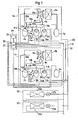
- the air conditioner according to this embodiment includes a refrigerant circuit formed by connecting a plurality of outdoor units 1a and 1b in parallel to an external liquid conduit 20 and an external gas conduit 21, and by connecting a plurality of indoor units 22 and 23 in parallel to the external liquid conduit 20 and external gas conduit 21.
- the number of the outdoor units 1a and 1b and the number of the indoor units 22 and 23 may be appropriately selected in accordance with the load to be air-conditioned.
- the indoor unit 22 includes a heat exchanger 22a and an expansion valve 22b.
- the indoor unit 23 includes a heat exchanger 23a and an expansion valve 23b. As described above, the indoor units 22 and 23 are connected to the external liquid conduit 20 and external gas conduit 21.
- each constituent part of the outdoor unit 1b is designated by the same reference numeral as the corresponding constituent part of the outdoor unit 1a, but suffixed with a reference character "b".
- the outdoor unit 1a includes two compressors, that is, a first compressor 2a and a second compressor 3a.
- the first and second compressors 2a and 3a are connected, at outlets thereof, in parallel to a discharge tube 9a, which is, in turn, connected to a liquid separator 4a.
- the liquid separator 4a is connected, at an outlet thereof, to the external liquid conduit 20 via a four-way valve 5a, heat exchanger 6a, and a liquid collector 7a, in this order.
- Each of the compressors 2a and 3a is a low-pressure shell type compressor, in which the internal pressure of a compressor shell thereof during operation of the compressor is lower than the internal pressure of the compressor shell in a stopped state of the compressor.
- the four-way valve 5a is switched between a cooling mode position where refrigerant flows in a direction indicated by a solid-line arrow C (the state of FIG. 1) during a cooling operation and a heating mode position where refrigerant flows in a direction indicated by a dotted-line arrow H during a heating operation.
- a liquid separator 8a is connected to the external gas conduit 21 through the four-way valve of the outdoor unit 1a.
- the branched suction tubes 10a and 11a of the first and second compressors 2a and 3a are connected to an outlet of the liquid separator 8a.
- the suction tube 10a of the first compressor 2a is connected to an inlet of the first compressor 2a.
- the suction tube 11a of the second compressor 3a is connected to an inlet of the second compressor 3a.
- the inlet of each of the first and second compressors 2a and 3a communicates with an oil reservoir provided in the associated compressor.
- An oil return tube 14a is connected to the liquid separator 4a.
- the oil return tube 14a is also connected to an outlet of the liquid separator 8a via a pressure reducer 28a.
- a bypass tube 29a is connected to the oil return tube 14a to bypass oil from the oil return tube 14a to the suction tube 10a of the first compressor 2a.
- a third opening/closing valve 18a is arranged in the bypass tube 29a.
- a check valve 15a is arranged in the suction tube 10a of the first compressor 2a downstream from the connection between the bypass tube 29a and the suction tube 10a of the first compressor 2a.
- the check valve 15a, bypass tube 29a and third opening/closing valve 18a are installed only at the side of the first compressor 2a. These elements are not installed at the side of the second compressor 3a. Even in the case in which an increased number of compressors are used, the check valve 15a, bypass tube 29a and third opening/closing valve 18a are installed only at the side of the first compressor 2a.
- This arrangement is applied to the outdoor unit 1b in the same manner as the indoor unit 1a. That is, a check valve 15b, bypass tube 29b and third opening/closing valve 18b are installed only at the side of the first compressor 2b of the outdoor unit 1b. These elements are not installed in the other compressor of the outdoor unit 1b, that is, the second compressor 3b.
- the first and second compressors 2a and 3a are connected by an oil equalizing tube to feed surplus oil between the first and second compressors 2a and 3a.
- the oil equalizing tubes of the outdoor units 1a and 1b are connected by an external oil equalizing tube (connecting tube) 19.
- the first-compressor oil equalizing tube 12a connected to the first compressor 2a is connected with the second-compressor oil equalizing tube 13a connected to the second compressor 3a in the outdoor unit 1a.
- the first-compressor oil equalizing tube 12b connected to the first compressor 2b is connected with the second-compressor oil equalizing tube 13b connected to the second compressor 3b in the outdoor unit 1b.
- the external oil equalizing tube 19 is connected, at opposite ends thereof, to the connection between the first-compressor oil equalizing tube 12a and the second-compressor oil equalizing tube 13a in the outdoor unit 1a and the connection between the first-compressor oil equalizing tube 12b and the second-compressor oil equalizing tube 13b in the outdoor unit 1b.
- a first opening/closing valve 16a is arranged in the second-compressor oil equalizing tube 13a.
- a second opening/closing valve 17a is installed in the outdoor unit 1a near the connection between the second-compressor oil equalizing tube 13a and the external oil equalizing tube 19.
- a second opening/closing valve 17b is installed near the connection between a second-compressor oil equalizing tube 13b corresponding to the second compressor oil equalizing tube 13a and the external oil equalizing tube 19.
- oil equalization controller 24 includes a timer 25, an opening/closing controller 26 to control opening/closing of the first opening/closing valves (oil equalizing tube opening/closing valves) 16a and 16b, second opening/closing valves (connecting tube opening/closing valves) 17a and 17b, third opening/closing valves (bypass opening/closing valves) 18a and 18b, and a compressor controller 27 to control operations of the first compressors 2a and 2b and operations of the second compressors 3a and 3b.
- an opening/closing controller 26 to control opening/closing of the first opening/closing valves (oil equalizing tube opening/closing valves) 16a and 16b
- second opening/closing valves connecting tube opening/closing valves 17a and 17b
- third opening/closing valves bypass opening/closing valves
- opening/closing of the first opening/closing valves 16a and 16b, second opening/closing valves 17a and 17b, and third opening/closing valves 18a and 18b are periodically controlled, and operations of the first compressors 2a and 2b and operations of the second compressors 3a and 3b are controlled, so that oil equalization is achieved in the first compressors 2a and 2b and second compressors 3a and 3b.
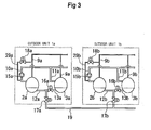
- FIG. 3 is a simplified version of FIG. 1, for easy understanding of the periodic control operation.
- constituent elements respectively corresponding to those of FIG. 1 are designated by the same reference numerals.
- the bypass tubes 29a and 29b are branched from the oil return tubes 14a and 14b, respectively, in the case of FIG. 3, they are branched from the discharge tubes 9a and 9b of the first compressors 2a and 2b, respectively, in the case of FIG. 3.
- the oil separators 4a and 4b are omitted.
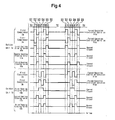
- a control operation is carried out for a time T, as shown in the time chart of FIG. 4.
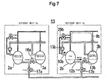
- the first compressors 2a and 2b and second compressors 3a and 3b perform normal operations thereof, respectively. That is, the expansion valves 22b and 23b are adjusted in accordance with a load to be air-conditioned. Under this condition, the first compressors 2a and 2b and second compressors 3a and 3b are operated. Thus, an air-conditioning control operation is carried out. In this case, accordingly, the first opening/closing valves 16a and 16b, second opening/closing valves 17a and 17b, and third opening/closing valves 18a and 18b are maintained in a closed state.
- an oil equalizing operation is performed in six operations S1 to S6 for a time T for each of the six operations S1 to S6 by switching the operations of the first compressors 2a and 2b and the operations of the second compressors 3a and 3b, and simultaneously opening/closing the first opening/closing valves 16a and 16b, second opening valves 17a and 17b, and third opening/closing valves 18a and 18b at intervals of the time T.
- the operations of the first compressors 2a and 2b, the operations of the second compressors 3a and 3b, and the opening/closing of the first opening/closing valves 16a and 16b, second opening valves 17a and 17b, and third opening/closing valves 18a and 18b are controlled.
- lubricant oil is collected in the first compressors 2a and 2b, which include respective check valves 15a and 15b, and respective third opening/closing valves 18a and 18b, and is then supplied from the first compressors 2a and 2b into other outdoor units.
- the first compressors 2a and 2b Upon supplying the lubricant oil, the first compressors 2a and 2b, in which the lubricant oil has been collected, are stopped. Under this condition, other compressors are forcibly operated to supply high-pressure gas into the first compressors 2a and 2b through the bypass tubes 29a and 29b, and thus, to sufficiently increase the internal pressure of the oil reservoirs of the first compressors 2a and 2b.
- each compressor selectively operates, in addition to the above-described controlled operation mode, in particular operation modes such as a forced operation mode and a stop mode.
- forced operation means to forcibly operate the compressors by desired power without using a normal compressor control method.
- stop means to stop the operations of the compressors.
- the first compressor 2a of the outdoor unit 1a is forcibly operated, whereas the second compressor 3a of the outdoor unit 1a is in a stopped state. Accordingly, the internal pressure of the first compressor 2a is lowered below the internal pressure of the shell of the stopped second compressor 3a, so that lubricant oil is fed from the second compressor 3a into the first compressor 2a via the second-compressor oil equalizing tube 13a and the first-compressor oil equalizing tube 12a (as indicated by a solid-line arrow), and is collected in the oil reservoir of the first compressor 2a.
- the first and second compressors 2b and 3b of the outdoor unit 1b are operated in a controlled operation mode.
- the first compressor 2a of the outdoor unit 1a is in a stopped state, whereas the second compressor 3a of the outdoor unit 1a is forcibly operated. Accordingly, the gas pressure of the second compressor 3a is applied to the first compressor 2a via the second-compressor suction tube 11a, which prevents a reverse flow therethrough by the discharge tube 9a, bypass tube 29a, and check valve 15a.
- the oil reservoir of the first compressor 2a is pressurized, so that lubricant oil is collected in the first compressor 2b of the outdoor unit 1b via the first-compressor oil equalizing tube 12a, the external oil equalizing tube 19, and the first-compressor oil equalizing tube 12b of the outdoor unit 1b (as indicated by a solid-line arrow).
- the second compressor 3b is operated in a controlled operation mode.
- there is no adverse affect on the flow of lubricant oil by the controlled operation of the second compressor 3b because the first opening/closing valve 16b is in a closed state.
- the second compressor 3b of the outdoor unit 1b is forcibly operated, whereas the first compressor 2b of the outdoor unit 1b is in a stopped state. Accordingly, the internal pressure of the second compressor 3b is lowered below the internal pressure of the shell of the stopped first compressor 2b, so that lubricant oil is fed from the first compressor 2b into the second compressor 3b via the first-compressor oil equalizing tube 12b and second-compressor oil equalizing tube 13b (as indicated by a solid-line arrow), and is collected in the oil reservoir of the second compressor 3b.
- the first and second compressors 2a and 3a of the outdoor unit 1a are operated in a controlled operation mode.
- the first opening/closing valve 16b is in a closed state. Accordingly, there is no flow of lubricant oil between the first and second compressors 2a and 3a. Also, there is no flow of lubricant oil between the outdoor units 1a and 1b because the second opening/closing valves 17a and 17b are in a closed state. Since the third opening/closing valve 18b is in a closed state in this case, the gas pressure of the second compressor 3b is applied to the oil reservoir of the first compressor 2b via the discharge tube 9b, bypass tube 29b, and first-compressor suction tube 10b. As a result, lubricant oil can be efficiently fed from the first compressor 2b into the second compressor 3b.
- the first compressor 2b of the outdoor unit 1b is forcibly operated, whereas the second compressor 3b of the outdoor unit 1b is in a stopped state. Accordingly, the internal pressure of the first compressor 2b is lowered below the internal pressure of the shell of the stopped second compressor 3b, so that lubricant oil is fed from the second compressor 3b into the first compressor 2b via the second-compressor oil equalizing tube 13b and first-compressor oil equalizing tube 12b (as indicated by a solid-line arrow), and is collected in the oil reservoir of the first compressor 2b.
- the first and second compressors 2a and 3a of the outdoor unit 1a are operated in a controlled operation mode.
- the first opening/closing valve 16a is in a closed state. Accordingly, there is no flow of lubricant oil between the first and second compressors 2a and 3a. Also, there is no flow of lubricant oil between the outdoor units 1a and 1b because the second opening/closing valves 17a and 17b are in a closed state.
- the second compressor 3b of the outdoor unit 1b is forcibly operated, whereas the first compressor 2b of the outdoor unit 1b is in a stopped state. Accordingly, the gas pressure of the second compressor 3b is applied to the first compressor 2b via the second-compressor suction tube 10b, which prevents a reverse flow therethrough by the discharge tube 9b, bypass tube 29b, and check valve 15b.
- the oil reservoir of the first compressor 2b is pressurized, so that lubricant oil is collected in the first compressor 2a of the outdoor unit 1a via the first-compressor oil equalizing tube 12b, the external oil equalizing tube 19, and the first-compressor oil equalizing tube 12a of the outdoor unit 1a (as indicated by a solid-line arrow).
- the second compressor 3a is operated in a controlled operation mode.
- there is no adverse affect on the flow of lubricant oil by the controlled operation of the second compressor 3a because the first opening/closing valve 16a is in a closed state.
- the second compressor 3a of the outdoor unit 1a is forcibly operated, whereas the first compressor 2a of the outdoor unit 1a is in a stopped state. Accordingly, the internal pressure of the second compressor 3a is lowered below the internal pressure of the shell of the stopped first compressor 2a, so that lubricant oil is fed from the first compressor 2a into the second compressor 3a via the first-compressor oil equalizing tube 12a and second-compressor oil equalizing tube 13a (as indicated by a solid-line arrow), and is collected in the oil reservoir of the second compressor 3a.
- the first and second compressors 2b and 3b of the outdoor unit 1b are operated in a controlled operation mode.
- the first opening/closing valve 16b is in a closed state. Accordingly, there is no flow of lubricant oil between the first and second compressors 2b and 3b. Also, there is no flow of lubricant oil between the outdoor units 1a and 1b because the second opening/closing valves 17a and 17b are in a closed state. Since the third opening/closing valve 18a is in a closed state in this case, the gas pressure of the second compressor 3a is applied to the oil reservoir of the first compressor 2a via the discharge tube 9a, bypass tube 29a, and first-compressor suction tube 10a. As a result, lubricant oil can be efficiently fed from the first compressor 2a into the second compressor 3a.
- lubricant oil is collected in the first compressors 2a and 2b, which are provided with respective check valves 15a and 15b and respective bypass tubes 29a and 29b, in accordance with the characteristics of a low-pressure shell type compressor in which a reduction in pressure occurs during operation of the compressor. Accordingly, it is possible to reliably and inexpensively perform a desired oil equalizing operation, using a simple operation to stop a desired compressor.
- oil equalization is performed between the first compressor 2b and the second compressor 3b in the outdoor unit 1b by feeding, into the second compressor 3b, the lubricant oil in the first compressor 2b supplied from the outdoor unit 1a at operation S2 shown in FIG. 6.
- oil equalization is performed between the first compressor 2a and the second compressor 3a in the outdoor unit 1a by feeding, into the second compressor 3a, the lubricant oil in the first compressor 2a supplied from the outdoor unit 1b at operation S5 shown in FIG. 9.
- oil equalization can be achieved, using simple operations. Accordingly, it is possible to easily manage the oil equalizing operation. Also, the oil equalization can be conveniently achieved because it is unnecessary to use detectors during a normal controlled operation.
- a method for performing an oil equalizing operation in accordance with a liquid level detection control operation carried out by the oil equalization controller 24 will be described with reference to the block diagram of FIG. 11, flow charts of FIGS. 12 to 16, and FIGS. 17 to 20.
- a compressor liquid level detector 30 is used in addition to the oil equalization controller 24 used for the above-described periodic control operation, as shown in FIG. 11.
- liquid level detection control operation based on the detection results of the compressor liquid level detector 30, opening/closing of the first opening/closing valves 16a and 16b, second opening/closing valves 17a and 17b, and third opening/closing valves 18a and 18b are controlled, and operations of the first compressors 2a and 2b and operations of the second compressors 3a and 3b are controlled, so that oil equalization is performed in the first compressors 2a and 2b and second compressors 3a and 3b.
- the liquid level detector may be implemented using a flow switch.
- FIG. 11 is basically the same as that of FIG. 1, except for the addition of the compressor liquid level detector 30, and thus, description thereof will be omitted.
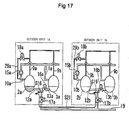
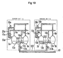
- FIGS. 17 to 20 which are used in association with descriptions given by the flow charts, are simplified versions, as in FIGS. 5 to 10 used for the above-mentioned periodic control operation.
- the term "first” used in the first compressors 2a, 2b and first opening/closing valves 16a and 16b, the term “second” used in the second compressors 3a and 3b and second opening/closing valves 17a and 17b, and the term “third” used in the third opening/closing valves 18a and 18b are omitted.
- the forced operation in the operation mode of the compressors is simply referred to as “operation”
- the controlled operation is simply referred to as "normal control”.
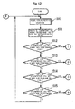
- a normal cooling/heating operation is performed, as shown in the flow chart of FIG. 12.
- all opening/closing valves are closed so that all compressors are operated in a normal control mode at operation S11.
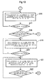
- operation S16 of FIG. 13 is executed to forcibly operate the first compressor 2a, to stop the second compressor 3a, and to operate the first and second compressors 2b and 3b in the controlled operation mode.
- operation S16 is executed to forcibly operate the first compressor 2a, to stop the second compressor 3a, and to operate the first and second compressors 2b and 3b in the controlled operation mode.
- only the first opening/closing valve 16a is opened, whereas the remaining opening/closing valves are maintained in a closed state.
- the condition established at operation S16 is maintained for a predetermined time at operation S17.
- a control operation is executed to operate the first and second compressors 2a and 3a in the controlled operation mode, to forcibly operate the first compressor 2b, and to stop the second compressor 3b.
- the first opening/closing valve 16b is opened, whereas the remaining opening/closing valves are maintained in a closed state.
- the condition established at operation S19 is maintained for a predetermined time at operation S20.
- a control operation is executed to operate the first and second compressors 2a and 3a in the controlled operation mode, to stop the first compressor 2b, and to forcibly operate the second compressor 3b.
- the first opening/closing valves 16a and 16b, and third opening/closing valve 18a are opened, whereas the second opening/closing valves 17a and 17b and third opening/closing valve 18b are closed.
- lubricant oil is moved from the first compressor 2b to the first compressor 2a, as indicated by arrow S21 in FIG. 17, thus increasing the oil level of the first compressor 2a.
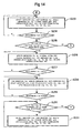
- operation S23 of FIG. 14 is executed to forcibly operate the second compressor 3a, to stop the first compressor 2a, and to operate the first and second compressors 2b and 3b in the controlled operation mode.
- operation S23 is maintained for a predetermined time at operation S24.
- a control operation is executed to operate the first and second compressors 2a and 3a in the controlled operation mode, to forcibly operate the first compressor 2b, and to stop the second compressor 3b.
- a control operation is executed to operate the first and second compressors 2a and 3a in the controlled operation mode, to forcibly operate the first compressor 2b, and to stop the second compressor 3b.
- only the first opening/closing valve 16b is opened, whereas the remaining opening/closing valves are maintained in a closed state.
- the condition established at operation S26 is maintained for a predetermined time at operation S27.
- a control operation is executed to stop the first compressors 2a and 2b and to forcibly operate the second compressors 3a and 3b.
- the first opening/closing valve 16b and third opening/closing valve 18a are closed, whereas the remaining opening/closing valves are opened.
- the condition established at operation S28 is maintained for a predetermined time at operation S29.
- a control operation is executed to stop the first compressor 2a, to forcibly operate the second compressor 3a, and to operate the first and second compressors 2b and 3b in the controlled operation mode.
- the first opening/closing valve 16b is opened, whereas the remaining opening/closing valves are maintained in a closed state.
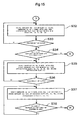
- operation S32 of FIG. 15 is executed to forcibly operate the first compressor 2b, to stop the second compressor 3b, and to operate the first and second compressors 2a and 3a in the controlled operation mode.
- operation S32 is maintained for a predetermined time at operation S33.
- a control operation is executed to operate the first and second compressors 2b and 3b in the controlled operation mode, to forcibly operate the first compressor 2a, and to stop the second compressor 3a.
- a control operation is executed to operate the first and second compressors 2b and 3b in the controlled operation mode, to forcibly operate the first compressor 2a, and to stop the second compressor 3a.
- only the first opening/closing valve 16a is opened, whereas the remaining opening/closing valves are maintained in a closed state.
- a control operation is executed to operate the first and second compressors 2b and 3b in the controlled operation mode, to stop the first compressor 2a, and to forcibly operate the second compressor 3a.
- the first opening/closing valves 16a and 16b and third opening/closing valve 18b are closed, whereas the second opening/closing valves 17a and 17b and third opening/closing valve 18b are opened.
- lubricant oil is moved from the first compressor 2a to the first compressor 2b, as indicated by arrow S37 in FIG. 19, thus increasing the oil level of the first compressor 2b.
- a control operation is executed at operation S39 of FIG. 16 to forcibly operate the second compressor 3b, to stop the first compressor 2b, and to operate the first and second compressors 2a and 3a in the controlled operation mode.
- a control operation is executed at operation S39 of FIG. 16 to forcibly operate the second compressor 3b, to stop the first compressor 2b, and to operate the first and second compressors 2a and 3a in the controlled operation mode.
- only the first opening/closing valve 16b is opened, whereas the remaining opening/closing valves are maintained in a closed state.
- the condition established at operation S39 is maintained for a predetermined time at operation S40.
- a control operation is executed to operate the first and second compressors 2b and 3b in the controlled operation mode, to forcibly operate the first compressor 2a, and to stop the second compressor 3a.
- a control operation is executed to operate the first and second compressors 2b and 3b in the controlled operation mode, to forcibly operate the first compressor 2a, and to stop the second compressor 3a.
- only the first opening/closing valve 16a is opened, whereas the remaining opening/closing valves are maintained in a closed state.
- Operation S44 is then executed.
- a control operation is executed to stop the first compressors 2a and 2b and to forcibly operate the second compressors 3a and 3b.
- the first opening/closing valve 16a and third opening/closing valve 18b are closed, whereas the remaining opening/closing valves are opened.
- the condition established at operation S44 is maintained for a predetermined time at operation S45.
- a control operation is executed to stop the first compressor 2b, to forcibly operate the second compressor 3b, and to operate the first and second compressors 2a and 3a in the controlled operation mode.
- the first opening/closing valve 16b is opened, whereas the remaining opening/closing valves are maintained in a closed state.
- lubricant oil is collected in the first compressors 2a and 2b, which are provided with respective check valves 15a and 15b and respective bypass tubes 29a and 29b, in accordance with the characteristics of a low-pressure shell type compressor in which a reduction in pressure occurs during operation of the compressor, through operations S16 and S19 of FIG. 17, operation S26 of FIG. 18, operations S32 and S35 of FIG. 19, and operation S42 of FIG. 20.
- oil equalization is achieved by feeding lubricant oil from one of the compressors connected in parallel to the other compressor through operations S23 and S31 of FIG. 18, and operations S39 and S47 of FIG. 20.
- the amounts of lubricant oil in all compressors 2a, 3a, 2b, and 3b are equalized within a reduced period of time, similar to the previously described embodiment.
- a reliable and efficient oil system is implemented. Accordingly, the restriction on the length and diameter of pipes is reduced.
- a reduction in costs is achieved in accordance with a reduction in the number of constituent elements used in the air conditioner.
- connections which are connected to the bypass tubes 29a and 29b of the air conditioner upstream from the bypass tubes 29a and 29b, are not limited to the oil return tubes 14a and 14b.
- These connections may be any of the sections through which high pressure gas or high pressure liquid passes, such as the discharge pipes 9a and 9b or the uppermost parts of the liquid collectors 7a and 7b, as long as the sections are at the side of the first compressors 2a and 2b.
- the oil equalization can be achieved without the user being aware because it is unnecessary to use detectors during a normal controlled operation. Accordingly, it is possible to easily manage the oil equalizing operation by controlling the air conditioner such that the oil equalizing operation is appropriately performed prior to the normal controlled operation. Thus, reliable oil equalization can be achieved.
Landscapes
- Engineering & Computer Science (AREA)
- Mechanical Engineering (AREA)
- General Engineering & Computer Science (AREA)
- Physics & Mathematics (AREA)
- Thermal Sciences (AREA)
- Air Conditioning Control Device (AREA)
- Compression-Type Refrigeration Machines With Reversible Cycles (AREA)
- Control Of Positive-Displacement Pumps (AREA)
Abstract
An air conditioner including an outdoor unit (1a/1b)
including a first compressor and a second compressor
connected in parallel to the first compressor, an outdoor
unit (1a/1b) connected in parallel to the outdoor unit
(1a/1b), the outdoor unit (1a/1b) including a first
compressor and a second compressor connected in parallel
to the first compressor, the outdoor units (1a,1b) being
connected in parallel to indoor units (22,23), the
compressors (2a,3a) being connected by first-compressor
oil equalizing tubes and second-compressor oil equalizing
tubes to feed surplus oil in the compressors (2a,3a), the
oil equalizing tubes being connected by an external oil
equalizing tube, wherein oil equalization is performed by
collecting lubricant oil in the first compressor of the
outdoor unit (1a/1b), pressurizing the collected lubricant
oil by a discharge pressure of another compressor
connected in parallel to the first compressor in the same
outdoor unit (1a/1b), that is, the second compressor, and
feeding the pressurized lubricant oil into the first
compressor or second compressor of the other outdoor unit
(1a/1b). Accordingly, it is possible to reduce the oil
equalizing operation time. Also, there is no restriction
on the length of oil equalizing tubes. Accordingly, an
enhancement in reliability is achieved.
Description
- The present invention relates to an air conditioner in which a plurality of outdoor units each including a plurality of low-pressure shell type compressors are connected, and a method for performing an oil equalizing operation in the air conditioner.
- An air conditioner, in which a plurality of outdoor units and a plurality of indoor units are connected in parallel to a refrigerant circuit, is well known. Each of the outdoor and indoor units may include a plurality of compressors. In such an air conditioner, an oil reservoir is provided in each compressor. The oil reservoirs of the compressors are communicated via oil equalizing tubes so that an oil equalizing operation can be performed to prevent occurrence of a phenomenon that oil is not supplied to one or more of the compressors.
- An example of such a structure will be described with reference to FIG. 21. In FIG. 21, "A" designates an outdoor unit of an air conditioner. The outdoor unit A is connected in parallel to another outdoor unit B while being connected in parallel to an indoor unit (not shown). The outdoor unit A includes a
first compressor 32a and asecond compressor 33a connected in parallel. The outdoor unit B includes afirst compressor 32b and asecond compressor 33b connected in parallel.Refrigerant discharge tubes 39a are connected to thecompressors Refrigerant discharge tubes 39b are connected to thecompressors refrigerant discharge tubes refrigerant suction tubes compressors compressors - The first and
second compressors tube 43a to feed surplus oil between thecompressors second compressors tube 43b to feed surplus oil between thecompressors tubes connecting tube 49. -
Bypass tubes 59a and 59b are branched fromrespective discharge tubes compressors bypass tubes 59a and 59b are connected to thesuction tubes Check valves suction tubes bypass tube 59a and 59b. - Bypass opening/
closing valves bypass tubes 59a and 59b, respectively. The oil equalizingtubes closing valves - When an oil equalizing operation is performed during operations of the
compressors closing valve 48a of the bypass tube 59a connected to thedischarge tube 39a of thefirst compressor 32a of the outdoor unit A, the discharge pressure of thefirst compressor 32a is applied to thefirst compressor 32a, so that the oil reservoir of thefirst compressor 32a has a pressure higher than those of the remaining compressors. Accordingly, when all the oil equalizing opening/closing valves first compressor 32a is supplied into thesecond compressor 33a of the outdoor unit A and the first andsecond compressors closing valves compressors - In the above-mentioned conventional air conditioner, however, the pressure of each oil reservoir is hardly increased because the air conditioner has an arrangement in which an increase in the internal pressures of the compressors is achieved by operating the compressors in an opened state of the bypass opening/
closing valves - Moreover, it is necessary to install the
bypass tubes 59a and 59b and bypass opening/closing valves discharge tubes compressors check valves suction tubes compressors - Additional aspects and/or advantages of the invention will be set forth in part in the description which follows and, in part, will be apparent from the description, or may be learned by practice of the invention.
- The present invention has been made in view of the above-mentioned problems. The present invention provides an air conditioner capable of achieving a reduction in oil equalizing operation time, and eliminating a restriction on the length of oil equalizing tubes, and thus, achieving an enhancement in system reliability and a reduction in costs, and to provide a method for performing an oil equalizing operation in the air conditioner.
- According to the present invention there is provided an apparatus and method as set forth in the appended claims. Preferred features of the invention will be apparent from the dependent claims, and the description which follows.
- In accordance with one aspect, the present invention provides an air conditioner including a plurality of outdoor units connected in parallel with an indoor unit, each of the outdoor units including a plurality of compressors connected in parallel, the compressors being connected by an oil equalizing tube to feed surplus oil in each of the compressors to the remaining compressors, and a connecting tube to connect the oil equalizing tubes of the outdoor units, wherein each of the outdoor units further includes a check valve arranged at a suction tube connected to one of the compressors included in each outdoor unit, a bypass tube arranged at an outlet of at least one of the remaining compressors, and a bypass opening/closing valve arranged in the bypass tube, wherein the bypass tube is connected to the suction tube downstream from the check valve, wherein an oil equalizing tube opening/closing valve is arranged in the oil equalizing tube of each outdoor unit to cut off flow of lubricant oil through the oil equalizing tube, and wherein a connecting tube opening/closing valve is arranged in the connecting tube.
- The bypass tube, bypass opening/closing valve, and check valve may be installed in only one of the compressors of each outdoor unit.
- Each of the compressors may be a low-pressure shell type compressor in which an internal pressure of a shell of the compressor during an operation of the compressor is lower than an internal pressure of the shell in a stopped state of the compressor.
- Accordingly, it is possible to feed lubricant oil from one compressor to another compressor connected in parallel to the one compressor by stopping the one compressor.
- In accordance with another aspect, the present invention provides a method for performing an oil equalizing operation in an air conditioner including a plurality of outdoor units connected in parallel with an indoor unit, each of the outdoor units including a plurality of compressors connected in parallel, the compressors being connected by an oil equalizing tube to feed surplus oil in each of the compressors to the remaining compressors, and a connecting tube to connect the oil equalizing tubes of the outdoor units, including: collecting lubricant oil in one compressor of one of the outdoor units; pressurizing the collected lubricant oil by a discharge pressure of another compressor, which is connected in parallel to said one compressor in the same outdoor unit; and feeding the pressurized lubricant oil to one compressor of another outdoor unit via an oil equalizing tube and a connecting tube to achieve oil equalization.
- Accordingly, it is possible to achieve oil equalization by effectively using the discharge pressure of said another compressor.
- In accordance with another aspect, the present invention provides a method for performing an oil equalizing operation in an air conditioner including a plurality of outdoor units connected in parallel with an indoor unit, each of the outdoor units including a plurality of compressors connected in parallel, the compressors being connected by an oil equalizing tube to feed surplus oil in each of the compressors to the remaining compressors, and a connecting tube to connect the oil equalizing tubes of the outdoor units, comprising: collecting lubricant oil in one of the compressors in one of the outdoor units, which can apply, to an oil reservoir in the compressor, a discharge pressure of another compressor in the same outdoor unit; pressurizing the collected lubricant oil by the discharge pressure of said another compressor in the same outdoor unit, and feeding the pressurized lubricant oil to one compressor of another outdoor unit via an oil equalizing tube and a connecting tube; and feeding lubricant oil among the compressors of the same outdoor unit.
- Accordingly, it is possible to uniformly supply lubricant oil into all compressors.
- Oil equalization may be performed by sequentially supplying lubricant oil into the compressors of the outdoor units by collecting lubricant oil in one of the compressors in one of the outdoor units, which can apply, to an oil reservoir in the compressor, a discharge pressure of another compressor in the same outdoor unit, pressurizing the collected lubricant oil by the discharge pressure of said another compressor in the same outdoor unit, and feeding the pressurized lubricant oil to one compressor of another outdoor unit via an oil equalizing tube and a connecting tube, and feeding lubricant oil among the compressors of the same outdoor unit.
- Accordingly, it is possible to achieve oil equalization using a simple operation.
- The oil equalization may be performed by incorporating, in a controlled operation of the air conditioner, an oil equalizing operation to sequentially supply lubricant oil into the compressors, the oil equalizing operation including collecting lubricant oil in one of the compressors in one of the outdoor units, which can apply, to an oil reservoir in the compressor, a discharge pressure of another compressor in the same outdoor unit, pressurizing the collected lubricant oil by the discharge pressure of said another compressor in the same outdoor unit, and feeding the pressurized lubricant oil to one compressor of another outdoor unit via an oil equalizing tube and a connecting tube, and feeding lubricant oil among the compressors of the same outdoor unit.
- Accordingly, oil equalization can be achieved without the user being aware because it is unnecessary to use detectors during a normal controlled operation.
- The oil equalization may be performed, starting from the collection of lubricant oil, when it is detected that an oil level in the oil reservoir of a particular one of the compressors is lower than a predetermined level.
- Accordingly, it is possible to efficiently achieve oil equalization because it is possible to reliably supply lubricant oil into compressors, which preferentially require supply of lubricant oil.
- In accordance with another aspect, the present invention provides a method for performing an oil equalizing operation in an air conditioner including a plurality of outdoor units connected in parallel with an indoor unit, each of the outdoor units including a plurality of compressors connected in parallel, the compressors being connected by an oil equalizing tube to feed surplus oil in each of the compressors to the remaining compressors, and a connecting tube to connect the oil equalizing tubes of the outdoor units, each of the outdoor units further including a bypass tube connected to a discharge tube of the outdoor unit, the bypass tube communicating with a suction tube of one of the compressors in the outdoor unit only at an outlet of said one compressor, a bypass opening/closing valve arranged in the bypass tube, a check valve arranged at the suction tube upstream from a connection between the bypass tube and the suction tube, an oil equalizing tube opening/closing valve arranged in the oil equalizing tube of the outdoor unit to cut off flow of lubricant oil through the oil equalizing tube, and a connecting tube opening/closing valve arranged in the connecting tube, wherein oil equalization is performed by: collecting lubricant oil in the compressor, which includes the discharge tube connected with the bypass tube; applying, to the collected lubricant oil, a discharge pressure of another compressor, which is connected in parallel to said one compressor in the same outdoor unit, via the bypass tube opened by the bypass opening/closing valve, and the suction tube preventing a reverse flow therethrough by the check valve, thereby pressurizing the collected lubricant oil; and feeding the pressurized lubricant oil to one compressor of another outdoor unit via the oil equalizing tube opened by the oil equalizing tube opening/closing valve and the connecting tube opened by the connecting tube opening/closing valve.
- Additional aspects and/or advantages of the invention will be set forth in part in the description which follows and, in part, will be obvious from the description, or may be learned by practice of the invention.
- For a better understanding of the invention, and to show how embodiments of the same may be carried into effect, reference will now be made, by way of example, to the accompanying diagrammatic drawings in which:
- FIG. 1 is a circuit diagram illustrating the entire configuration of an air conditioner according to an embodiment of the present invention;
- FIG. 2 is a block diagram illustrating an oil equalization controller included in the air conditioner of FIG. 1;
- FIG. 3 is a schematic view illustrating a part of FIG. 1;
- FIG. 4 is a time chart according to a method for performing an oil equalizing operation in accordance with a first embodiment of the present invention;
- FIG. 5 is a schematic view illustrating an oil equalizing operation;
- FIG. 6 is a schematic view illustrating an oil equalizing operation;
- FIG. 7 is a schematic view illustrating an oil equalizing operation;
- FIG. 8 is a schematic view illustrating an oil equalizing operation;
- FIG. 9 is a schematic view illustrating an oil equalizing operation;
- FIG. 10 is a schematic view illustrating an oil equalizing operation;
- FIG. 11 is a block diagram illustrating an oil equalization controller included in an air conditioner according to a second embodiment of the present invention;
- FIG. 12 is a flow chart illustrating a method for performing an oil equalizing operation in accordance with a second embodiment of the present invention;
- FIG. 13 is a flow chart illustrating the method for performing an oil equalizing operation in accordance with the second embodiment of the present invention;
- FIG. 14 is a flow chart illustrating the method for performing an oil equalizing operation in accordance with the second embodiment of the present invention;
- FIG. 15 is a flow chart illustrating the method for performing an oil equalizing operation in accordance with the second embodiment of the present invention;
- FIG. 16 is a flow chart illustrating the method for performing an oil equalizing operation in accordance with the second embodiment of the present invention;
- FIG. 17 is a schematic view illustrating an oil equalizing operation;
- FIG. 18 is a schematic view illustrating an oil equalizing operation;
- FIG. 19 is a schematic view illustrating an oil equalizing operation;
- FIG. 20 is a schematic view illustrating an oil equalizing operation; and
- FIG. 21 is a schematic view illustrating a part of a conventional air conditioner.
-
- Reference will now be made in detail to the embodiments of the present invention, examples of which are illustrated in the accompanying drawings, wherein like reference numerals refer to the like elements throughout. The embodiments are described below to explain the present invention by referring to the figures.
- First, an air conditioner according to an embodiment of the present invention will be described with reference to FIGS. 1 to 10. The air conditioner according to this embodiment includes a refrigerant circuit formed by connecting a plurality of
outdoor units liquid conduit 20 and anexternal gas conduit 21, and by connecting a plurality ofindoor units liquid conduit 20 andexternal gas conduit 21. The number of theoutdoor units indoor units - The
indoor unit 22 includes aheat exchanger 22a and anexpansion valve 22b. Theindoor unit 23 includes aheat exchanger 23a and anexpansion valve 23b. As described above, theindoor units liquid conduit 20 andexternal gas conduit 21. - Since the
outdoor units outdoor unit 1a. Also, each constituent part of theoutdoor unit 1b is designated by the same reference numeral as the corresponding constituent part of theoutdoor unit 1a, but suffixed with a reference character "b". - In the illustrated case, the
outdoor unit 1a includes two compressors, that is, afirst compressor 2a and asecond compressor 3a. The first andsecond compressors discharge tube 9a, which is, in turn, connected to aliquid separator 4a. Theliquid separator 4a is connected, at an outlet thereof, to the externalliquid conduit 20 via a four-way valve 5a, heat exchanger 6a, and a liquid collector 7a, in this order. Each of thecompressors - A liquid separator 8a is connected to the
external gas conduit 21 through the four-way valve of theoutdoor unit 1a. Thebranched suction tubes second compressors suction tube 10a of thefirst compressor 2a is connected to an inlet of thefirst compressor 2a. Thesuction tube 11a of thesecond compressor 3a is connected to an inlet of thesecond compressor 3a. The inlet of each of the first andsecond compressors - An
oil return tube 14a is connected to theliquid separator 4a. Theoil return tube 14a is also connected to an outlet of the liquid separator 8a via apressure reducer 28a. - A
bypass tube 29a is connected to theoil return tube 14a to bypass oil from theoil return tube 14a to thesuction tube 10a of thefirst compressor 2a. A third opening/closing valve 18a is arranged in thebypass tube 29a. - A
check valve 15a is arranged in thesuction tube 10a of thefirst compressor 2a downstream from the connection between thebypass tube 29a and thesuction tube 10a of thefirst compressor 2a. - Thus, in the
outdoor unit 1a, thecheck valve 15a,bypass tube 29a and third opening/closing valve 18a are installed only at the side of thefirst compressor 2a. These elements are not installed at the side of thesecond compressor 3a. Even in the case in which an increased number of compressors are used, thecheck valve 15a,bypass tube 29a and third opening/closing valve 18a are installed only at the side of thefirst compressor 2a. This arrangement is applied to theoutdoor unit 1b in the same manner as theindoor unit 1a. That is, acheck valve 15b,bypass tube 29b and third opening/closing valve 18b are installed only at the side of thefirst compressor 2b of theoutdoor unit 1b. These elements are not installed in the other compressor of theoutdoor unit 1b, that is, thesecond compressor 3b. - The first and
second compressors second compressors outdoor units oil equalizing tube 12a connected to thefirst compressor 2a is connected with the second-compressoroil equalizing tube 13a connected to thesecond compressor 3a in theoutdoor unit 1a. The first-compressoroil equalizing tube 12b connected to thefirst compressor 2b is connected with the second-compressoroil equalizing tube 13b connected to thesecond compressor 3b in theoutdoor unit 1b. The externaloil equalizing tube 19 is connected, at opposite ends thereof, to the connection between the first-compressoroil equalizing tube 12a and the second-compressoroil equalizing tube 13a in theoutdoor unit 1a and the connection between the first-compressoroil equalizing tube 12b and the second-compressoroil equalizing tube 13b in theoutdoor unit 1b. - A first opening/
closing valve 16a is arranged in the second-compressoroil equalizing tube 13a. A second opening/closing valve 17a is installed in theoutdoor unit 1a near the connection between the second-compressoroil equalizing tube 13a and the externaloil equalizing tube 19. In theoutdoor unit 1b, a second opening/closing valve 17b is installed near the connection between a second-compressoroil equalizing tube 13b corresponding to the second compressoroil equalizing tube 13a and the externaloil equalizing tube 19. - As shown in FIG. 2,
oil equalization controller 24 includes atimer 25, an opening/closing controller 26 to control opening/closing of the first opening/closing valves (oil equalizing tube opening/closing valves) 16a and 16b, second opening/closing valves (connecting tube opening/closing valves) 17a and 17b, third opening/closing valves (bypass opening/closing valves) 18a and 18b, and acompressor controller 27 to control operations of thefirst compressors second compressors - Hereinafter, a method for performing an oil equalizing operation in accordance with a control operation periodically carried out by the
oil equalization controller 24 will be described with reference to the time chart of FIG. 4 and FIGS. 5 to 10. In accordance with this control operation, opening/closing of the first opening/closing valves closing valves closing valves first compressors second compressors first compressors second compressors - The following description will be given with reference to FIG. 3, which is a simplified version of FIG. 1, for easy understanding of the periodic control operation. In FIG. 3, constituent elements respectively corresponding to those of FIG. 1 are designated by the same reference numerals. Although the
bypass tubes oil return tubes discharge tubes first compressors oil separators 4a and 4b are omitted. - First, a control operation is carried out for a time T, as shown in the time chart of FIG. 4. Under this control operation, the
first compressors second compressors expansion valves first compressors second compressors closing valves closing valves closing valves - Next, an oil equalizing operation is performed in six operations S1 to S6 for a time T for each of the six operations S1 to S6 by switching the operations of the
first compressors second compressors closing valves second opening valves closing valves first compressors second compressors closing valves second opening valves closing valves Operation 1Operation 2Operation 3Operation 4Operation 5Operation 6Outdoor Unit 1a First Compressor 2a Forced Operation Stop Controlled Operation Controlled Operation Forced Operation Stop Second Compressor 3a Stop Forced Operation Controlled Operation Controlled Operation Controlled Operation Forced Operation First Opening/ Closi ng Valve 16aOpened Closed Closed Closed Closed Opened Second Opening/ Closi ng Valve 17aClosed Opened Closed Closed Opened Closed Third Opening/ Closi ng Valve 18aClosed Opened Closed Closed Closed Opened Outdoor Unit 1b First Compressor 2b Controlled Operation Forced Operation Stop Forced Operation Stop Controlled Operation Second Compressor 3b Controlled Operation Controlled Operation Forced Operation Stop Stop Forced Operation Controlled Operation First Opening/ Closi ng Valve 16bClosed Closed Opened Opened Closed Closed Second Opening/ Closi ng Valve 17bClosed Opened Closed Closed Opened Closed Third Opening/ Closi ng Valve 18bClosed Closed Opened Closed Opened Closed - In the oil equalizing operation, lubricant oil is collected in the
first compressors respective check valves closing valves first compressors first compressors first compressors bypass tubes first compressors - During the oil equalizing operation, each compressor selectively operates, in addition to the above-described controlled operation mode, in particular operation modes such as a forced operation mode and a stop mode. Here, "forced operation" means to forcibly operate the compressors by desired power without using a normal compressor control method. Also, as is the definition of the word "stop", "stop" used herein means to stop the operations of the compressors.
- At operation S1 shown in FIG. 5, the
first compressor 2a of theoutdoor unit 1a is forcibly operated, whereas thesecond compressor 3a of theoutdoor unit 1a is in a stopped state. Accordingly, the internal pressure of thefirst compressor 2a is lowered below the internal pressure of the shell of the stoppedsecond compressor 3a, so that lubricant oil is fed from thesecond compressor 3a into thefirst compressor 2a via the second-compressoroil equalizing tube 13a and the first-compressoroil equalizing tube 12a (as indicated by a solid-line arrow), and is collected in the oil reservoir of thefirst compressor 2a. In this case, the first andsecond compressors outdoor unit 1b are operated in a controlled operation mode. However, there is no flow of lubricant oil between the first andsecond compressors closing valve 16b is in a closed state. Also, there is no flow of lubricant oil between theoutdoor units closing valves - At operation S2 shown in FIG. 6, the
first compressor 2a of theoutdoor unit 1a is in a stopped state, whereas thesecond compressor 3a of theoutdoor unit 1a is forcibly operated. Accordingly, the gas pressure of thesecond compressor 3a is applied to thefirst compressor 2a via the second-compressor suction tube 11a, which prevents a reverse flow therethrough by thedischarge tube 9a,bypass tube 29a, andcheck valve 15a. As a result, the oil reservoir of thefirst compressor 2a is pressurized, so that lubricant oil is collected in thefirst compressor 2b of theoutdoor unit 1b via the first-compressoroil equalizing tube 12a, the externaloil equalizing tube 19, and the first-compressoroil equalizing tube 12b of theoutdoor unit 1b (as indicated by a solid-line arrow). In this case, thesecond compressor 3b is operated in a controlled operation mode. However, there is no adverse affect on the flow of lubricant oil by the controlled operation of thesecond compressor 3b because the first opening/closing valve 16b is in a closed state. Also, there is no adverse affect on the flow of lubricant oil by the forced operation of thesecond compressor 3a. - At operation S3 shown in FIG. 7, the
second compressor 3b of theoutdoor unit 1b is forcibly operated, whereas thefirst compressor 2b of theoutdoor unit 1b is in a stopped state. Accordingly, the internal pressure of thesecond compressor 3b is lowered below the internal pressure of the shell of the stoppedfirst compressor 2b, so that lubricant oil is fed from thefirst compressor 2b into thesecond compressor 3b via the first-compressoroil equalizing tube 12b and second-compressoroil equalizing tube 13b (as indicated by a solid-line arrow), and is collected in the oil reservoir of thesecond compressor 3b. In this case, the first andsecond compressors outdoor unit 1a are operated in a controlled operation mode. Also, the first opening/closing valve 16b is in a closed state. Accordingly, there is no flow of lubricant oil between the first andsecond compressors outdoor units closing valves closing valve 18b is in a closed state in this case, the gas pressure of thesecond compressor 3b is applied to the oil reservoir of thefirst compressor 2b via thedischarge tube 9b,bypass tube 29b, and first-compressor suction tube 10b. As a result, lubricant oil can be efficiently fed from thefirst compressor 2b into thesecond compressor 3b. - At operation S4 shown in FIG. 8, the
first compressor 2b of theoutdoor unit 1b is forcibly operated, whereas thesecond compressor 3b of theoutdoor unit 1b is in a stopped state. Accordingly, the internal pressure of thefirst compressor 2b is lowered below the internal pressure of the shell of the stoppedsecond compressor 3b, so that lubricant oil is fed from thesecond compressor 3b into thefirst compressor 2b via the second-compressoroil equalizing tube 13b and first-compressoroil equalizing tube 12b (as indicated by a solid-line arrow), and is collected in the oil reservoir of thefirst compressor 2b. In this case, the first andsecond compressors outdoor unit 1a are operated in a controlled operation mode. Also, the first opening/closing valve 16a is in a closed state. Accordingly, there is no flow of lubricant oil between the first andsecond compressors outdoor units closing valves - At operation S5 shown in FIG. 9, the
second compressor 3b of theoutdoor unit 1b is forcibly operated, whereas thefirst compressor 2b of theoutdoor unit 1b is in a stopped state. Accordingly, the gas pressure of thesecond compressor 3b is applied to thefirst compressor 2b via the second-compressor suction tube 10b, which prevents a reverse flow therethrough by thedischarge tube 9b,bypass tube 29b, andcheck valve 15b. As a result, the oil reservoir of thefirst compressor 2b is pressurized, so that lubricant oil is collected in thefirst compressor 2a of theoutdoor unit 1a via the first-compressoroil equalizing tube 12b, the externaloil equalizing tube 19, and the first-compressoroil equalizing tube 12a of theoutdoor unit 1a (as indicated by a solid-line arrow). In this case, thesecond compressor 3a is operated in a controlled operation mode. However, there is no adverse affect on the flow of lubricant oil by the controlled operation of thesecond compressor 3a because the first opening/closing valve 16a is in a closed state. Also, there is no adverse affect on the flow of lubricant oil by the forced operation of thesecond compressor 3b. - At operation S6 shown in FIG. 10, the
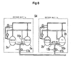
second compressor 3a of theoutdoor unit 1a is forcibly operated, whereas thefirst compressor 2a of theoutdoor unit 1a is in a stopped state. Accordingly, the internal pressure of thesecond compressor 3a is lowered below the internal pressure of the shell of the stoppedfirst compressor 2a, so that lubricant oil is fed from thefirst compressor 2a into thesecond compressor 3a via the first-compressoroil equalizing tube 12a and second-compressoroil equalizing tube 13a (as indicated by a solid-line arrow), and is collected in the oil reservoir of thesecond compressor 3a. In this case, the first andsecond compressors outdoor unit 1b are operated in a controlled operation mode. Also, the first opening/closing valve 16b is in a closed state. Accordingly, there is no flow of lubricant oil between the first andsecond compressors outdoor units closing valves closing valve 18a is in a closed state in this case, the gas pressure of thesecond compressor 3a is applied to the oil reservoir of thefirst compressor 2a via thedischarge tube 9a,bypass tube 29a, and first-compressor suction tube 10a. As a result, lubricant oil can be efficiently fed from thefirst compressor 2a into thesecond compressor 3a. - Thus, at operation S1 shown in FIG. 5 and operation S4 shown in FIG. 8, lubricant oil is collected in the
first compressors respective check valves respective bypass tubes - At operation S2 shown in FIG. 6 and operation S5 shown in FIG. 9, it is possible to achieve an oil equalizing operation in which the lubricant oil from the stopped compressor of one outdoor unit is rapidly supplied into the other outdoor unit within a reduced period of time by efficiently using pressure generated in accordance with a forced operation of the other compressor of the one-compressor-stopped outdoor unit (that is, the
second compressor - Also, at operation S3 shown in FIG. 7, oil equalization is performed between the
first compressor 2b and thesecond compressor 3b in theoutdoor unit 1b by feeding, into thesecond compressor 3b, the lubricant oil in thefirst compressor 2b supplied from theoutdoor unit 1a at operation S2 shown in FIG. 6. At operation S6 shown in FIG. 10, oil equalization is performed between thefirst compressor 2a and thesecond compressor 3a in theoutdoor unit 1a by feeding, into thesecond compressor 3a, the lubricant oil in thefirst compressor 2a supplied from theoutdoor unit 1b at operation S5 shown in FIG. 9. - In accordance with the sequential feeding of lubricant oil in the above-described manner, the amounts of lubricant oil in all
compressors check valve bypass tube first compressor outdoor unit - In particular, in accordance with the method for performing an oil equalizing operation, using a periodic control operation, as described above, oil equalization can be achieved, using simple operations. Accordingly, it is possible to easily manage the oil equalizing operation. Also, the oil equalization can be conveniently achieved because it is unnecessary to use detectors during a normal controlled operation.
- Hereinafter, a method for performing an oil equalizing operation in accordance with a liquid level detection control operation carried out by the
oil equalization controller 24 will be described with reference to the block diagram of FIG. 11, flow charts of FIGS. 12 to 16, and FIGS. 17 to 20. For the liquid level detection control operation, a compressorliquid level detector 30 is used in addition to theoil equalization controller 24 used for the above-described periodic control operation, as shown in FIG. 11. In accordance with the liquid level detection control operation, based on the detection results of the compressorliquid level detector 30, opening/closing of the first opening/closing valves closing valves closing valves first compressors second compressors first compressors second compressors - Thus, the configuration of FIG. 11 is basically the same as that of FIG. 1, except for the addition of the compressor
liquid level detector 30, and thus, description thereof will be omitted. Also, FIGS. 17 to 20, which are used in association with descriptions given by the flow charts, are simplified versions, as in FIGS. 5 to 10 used for the above-mentioned periodic control operation. - Also, in the flow charts shown in FIGS. 12 to 16, for simplification of description, the term "first" used in the
first compressors closing valves second compressors closing valves closing valves - At operation 10, a normal cooling/heating operation is performed, as shown in the flow chart of FIG. 12. In this case, accordingly, all opening/closing valves are closed so that all compressors are operated in a normal control mode at operation S11. During the operations of the compressors in the normal control mode, it is determined at operation S12 whether the oil level of the
first compressor 2a is not higher than a predetermined level. If the determination corresponds to "YES", the procedure proceeds to operation S16 of FIG. 13. On the other hand, if the determination corresponds to "NO", the procedure proceeds to operation S13. - At operation S13, it is determined whether the oil level of the
second compressor 3a is not higher than the predetermined level. If the determination corresponds to "YES", the procedure proceeds to operation S23 of FIG. 14. On the other hand, if the determination corresponds to "NO", the procedure proceeds to operation S14. - At operation S14, it is determined whether the oil level of the
first compressor 2b is not higher than the predetermined level. If the determination corresponds to "YES", the procedure proceeds to operation S32 of FIG. 15. On the other hand, if the determination corresponds to "NO", the procedure proceeds to operation S15. - At operation S15, it is determined whether the oil level of the
second compressor 3b is not higher than the predetermined level. If the determination corresponds to "YES", the procedure proceeds to operation S39 of FIG. 16. On the other hand, if the determination corresponds to "NO", the procedure proceeds to operation S10. - When it is determined at operation S12 that the oil level of the
first compressor 2a is not higher than the predetermined level, operation S16 of FIG. 13 is executed to forcibly operate thefirst compressor 2a, to stop thesecond compressor 3a, and to operate the first andsecond compressors closing valve 16a is opened, whereas the remaining opening/closing valves are maintained in a closed state. The condition established at operation S16 is maintained for a predetermined time at operation S17. - As a result, lubricant oil is moved from the
second compressor 3a to thefirst compressor 2a, as indicated by arrow S16 in FIG. 17, thus increasing the oil level of thefirst compressor 2a. - Thereafter, it is determined at operation S18 whether the oil level of the
first compressor 2a is not higher than the predetermined level. If the determination corresponds to "YES", the procedure proceeds to operation S19. On the other hand, if the determination corresponds to "NO", the procedure returns to operation S10 of FIG. 12. - At operation S19, a control operation is executed to operate the first and
second compressors first compressor 2b, and to stop thesecond compressor 3b. In this case, only the first opening/closing valve 16b is opened, whereas the remaining opening/closing valves are maintained in a closed state. The condition established at operation S19 is maintained for a predetermined time at operation S20. - As a result, lubricant oil is moved from the
second compressor 3b to thefirst compressor 2b, as indicated by arrow S19 in FIG. 17, thus increasing the oil level of thefirst compressor 2b. - At operation S21, a control operation is executed to operate the first and
second compressors first compressor 2b, and to forcibly operate thesecond compressor 3b. In this case, the first opening/closing valves closing valve 18a are opened, whereas the second opening/closing valves closing valve 18b are closed. It is then determined at operation S22 whether the oil level of thefirst compressor 2a is not higher than the predetermined level. If the determination corresponds to "YES", the procedure proceeds to operation S21. On the other hand, if the determination corresponds to "NO", the procedure returns to operation S10 of FIG. 12. - As a result, lubricant oil is moved from the
first compressor 2b to thefirst compressor 2a, as indicated by arrow S21 in FIG. 17, thus increasing the oil level of thefirst compressor 2a. - When it is determined at operation S13 of FIG. 12 that the oil level of the
second compressor 3a is not higher than the predetermined level, operation S23 of FIG. 14 is executed to forcibly operate thesecond compressor 3a, to stop thefirst compressor 2a, and to operate the first andsecond compressors closing valve 16a is opened, whereas the remaining opening/closing valves are maintained in a closed state. The condition established at operation S23 is maintained for a predetermined time at operation S24. - As a result, lubricant oil is moved from the
first compressor 2a to thesecond compressor 3a, as indicated by arrow S23 in FIG. 18, thus increasing the oil level of thesecond compressor 3a. - Thereafter, it is determined at operation S25 whether the oil level of the
second compressor 3a is not higher than the predetermined level. If the determination corresponds to "YES", the procedure proceeds to operation S26. On the other hand, if the determination corresponds to "NO", the procedure returns to operation S10 of FIG. 12. - At operation S26, a control operation is executed to operate the first and
second compressors first compressor 2b, and to stop thesecond compressor 3b. In this case, only the first opening/closing valve 16b is opened, whereas the remaining opening/closing valves are maintained in a closed state. The condition established at operation S26 is maintained for a predetermined time at operation S27. - As a result, lubricant oil is moved from the
second compressor 3b to thefirst compressor 2b, as indicated by arrow S26 in FIG. 18, thus increasing the oil level of thefirst compressor 2b. - At operation S28, a control operation is executed to stop the
first compressors second compressors closing valve 16b and third opening/closing valve 18a are closed, whereas the remaining opening/closing valves are opened. The condition established at operation S28 is maintained for a predetermined time at operation S29. - As a result, lubricant oil is moved from the
first compressor 2b to thesecond compressor 3a, as indicated by arrow S28 in FIG. 18, thus increasing the oil level of thesecond compressor 3a. - It is then determined at operation S30 whether the oil level of the
second compressor 3a is not higher than the predetermined level. If the determination corresponds to "YES", the procedure proceeds to operation S31. On the other hand, if the determination corresponds to "NO", the procedure returns to operation S10 of FIG. 12. - At operation S31, a control operation is executed to stop the
first compressor 2a, to forcibly operate thesecond compressor 3a, and to operate the first andsecond compressors closing valve 16b is opened, whereas the remaining opening/closing valves are maintained in a closed state. - As a result, lubricant oil is moved from the
first compressor 2a to thesecond compressor 3a, as indicated by arrow S31 in FIG. 18, thus increasing the oil level of thesecond compressor 3a. - When it is determined at operation S12 that the oil level of the
first compressor 2b is not higher than the predetermined level, operation S32 of FIG. 15 is executed to forcibly operate thefirst compressor 2b, to stop thesecond compressor 3b, and to operate the first andsecond compressors closing valve 16b is opened, whereas the remaining opening/closing valves are maintained in a closed state. The condition established at operation S32 is maintained for a predetermined time at operation S33. - As a result, lubricant oil is moved from the
second compressor 3b to thefirst compressor 2b, as indicated by arrow S32 in FIG. 19, thus increasing the oil level of thefirst compressor 2b. - Thereafter, it is determined at operation S34 whether the oil level of the
first compressor 2b is not higher than the predetermined level. If the determination corresponds to "YES", the procedure proceeds to operation S35. On the other hand, if the determination corresponds to "NO", the procedure returns to operation S10 of FIG. 12. - At operation S35, a control operation is executed to operate the first and
second compressors first compressor 2a, and to stop thesecond compressor 3a. In this case, only the first opening/closing valve 16a is opened, whereas the remaining opening/closing valves are maintained in a closed state. - As a result, lubricant oil is moved from the
second compressor 3a to thefirst compressor 2a, as indicated by arrow S35 in FIG. 19, thus increasing the oil level of thefirst compressor 2a. - At operation S37, a control operation is executed to operate the first and
second compressors first compressor 2a, and to forcibly operate thesecond compressor 3a. In this case, the first opening/closing valves closing valve 18b are closed, whereas the second opening/closing valves closing valve 18b are opened. Under this condition, it is determined at operation S38 whether the oil level of thefirst compressor 2b is not higher than the predetermined level. If the determination corresponds to "YES", the procedure proceeds to operation S37. On the other hand, if the determination corresponds to "NO", the procedure returns to operation S10 of FIG. 12. - In accordance with the control operation executed at operation S37, lubricant oil is moved from the
first compressor 2a to thefirst compressor 2b, as indicated by arrow S37 in FIG. 19, thus increasing the oil level of thefirst compressor 2b. - When it is determined at operation S15 of FIG. 12 that the oil level of the
second compressor 3b is not higher than the predetermined level, a control operation is executed at operation S39 of FIG. 16 to forcibly operate thesecond compressor 3b, to stop thefirst compressor 2b, and to operate the first andsecond compressors closing valve 16b is opened, whereas the remaining opening/closing valves are maintained in a closed state. The condition established at operation S39 is maintained for a predetermined time at operation S40. - As a result, lubricant oil is moved from the
first compressor 2b to thesecond compressor 3b, as indicated by arrow S39 in FIG. 20, thus increasing the oil level of thesecond compressor 3b. - Thereafter, it is determined at operation S41 whether the oil level of the
second compressor 3b is not higher than the predetermined level. If the determination corresponds to "YES", the procedure proceeds to operation S42. On the other hand, if the determination corresponds to "NO", the procedure returns to operation S10 of FIG. 12. - At operation S42, a control operation is executed to operate the first and
second compressors first compressor 2a, and to stop thesecond compressor 3a. In this case, only the first opening/closing valve 16a is opened, whereas the remaining opening/closing valves are maintained in a closed state. - As a result, lubricant oil is moved from the
second compressor 3a to thefirst compressor 2a, as indicated by arrow S42 in FIG. 20, thus increasing the oil level of thefirst compressor 2a. - Operation S44 is then executed. At operation S44, a control operation is executed to stop the
first compressors second compressors closing valve 16a and third opening/closing valve 18b are closed, whereas the remaining opening/closing valves are opened. The condition established at operation S44 is maintained for a predetermined time at operation S45. - As a result, lubricant oil is moved from the
first compressor 2a to thesecond compressor 3b, as indicated by arrow S44 in FIG. 20, thus increasing the oil level of thesecond compressor 3b. - Thereafter, it is determined at operation S46 whether the oil level of the
second compressor 3b is not higher than the predetermined level. If the determination corresponds to "YES", the procedure proceeds to operation S47. On the other hand, if the determination corresponds to "NO", the procedure returns to operation S10 of FIG. 12. - At operation S47, a control operation is executed to stop the
first compressor 2b, to forcibly operate thesecond compressor 3b, and to operate the first andsecond compressors closing valve 16b is opened, whereas the remaining opening/closing valves are maintained in a closed state. - As a result, lubricant oil is moved from the
first compressor 2b to thesecond compressor 3b, as indicated by arrow S47 in FIG. 20, thus increasing the oil level of thesecond compressor 3b. - Thus, even in the case of the method for performing an oil equalizing operation in accordance with the above-described liquid level detection control operation, lubricant oil is collected in the
first compressors respective check valves respective bypass tubes - Also, oil equalization is achieved by feeding lubricant oil from one of the compressors connected in parallel to the other compressor through operations S23 and S31 of FIG. 18, and operations S39 and S47 of FIG. 20.
- In accordance with this embodiment, therefore, the amounts of lubricant oil in all
compressors check valve bypass tube first compressor outdoor unit - In particular, in accordance with the method for performing an oil equalizing operation, using the liquid level detection control operation, it is possible to reliably supply lubricant oil into compressors, which preferably require a supply of lubricant oil due to the lowering of the liquid level during operation. Accordingly, there is an advantage in that efficient oil equalization can be achieved.
- The present invention is not limited to the above-described embodiments. For example, connections, which are connected to the
bypass tubes bypass tubes oil return tubes discharge pipes first compressors - As is apparent from the above description, in accordance with one aspect of the present invention, it is basically necessary to install a bypass tube, a bypass opening/closing valve, and a check valve only in one compressor of each outdoor unit. Thus, a reduction in factors causing failure is achieved. Accordingly, the costs may be reduced because an improvement in the reliability of the system is achieved in accordance with the reduction in factors causing failure. When the bypass opening/closing valve is opened during operation of the other compressor of each outdoor unit, pressure from the other compressor is applied to the suction side of the one compressor via the bypass tube and suction tube. Thus, it is possible to pressurize lubricant oil in the oil reservoir of the one compressor, using the applied pressure, and thus, to feed the lubricant oil to another outdoor unit via a connecting tube. Therefore, it is possible to reduce the time taken to complete the oil equalizing operation. Also, there is no restriction on the length of oil equalizing pipes. Therefore, it is possible to achieve a wider freedom of design, and a reduction in costs.
- In accordance with another aspect of the present invention, it is possible to feed lubricant oil from one of the compressors, connected in parallel, to the other compressor, using a simple operation to stop the one compressor. Thus, it is possible to reliably and inexpensively achieve oil equalization, using a simple operation to stop a desired compressor.
- In accordance with another aspect of the present invention, it is possible to reliably and efficiently achieve oil equalization during a normal operation mode because the oil equalization can be performed by efficiently using the discharge pressure of the other one of the compressors connected in parallel.
- In accordance with another aspect of the present invention, it is possible to uniformly supply all compressors, and thus, to more effectively perform an oil equalizing operation.
- In accordance with another aspect of the present invention, it is possible to achieve oil equalization, using a simple operation, and thus, to easily manage the oil equalizing operation.
- In accordance with another aspect of the present invention, the oil equalization can be achieved without the user being aware because it is unnecessary to use detectors during a normal controlled operation. Accordingly, it is possible to easily manage the oil equalizing operation by controlling the air conditioner such that the oil equalizing operation is appropriately performed prior to the normal controlled operation. Thus, reliable oil equalization can be achieved.
- In accordance with another aspect of the present invention, it is possible to efficiently achieve oil equalization because it is possible to reliably supply lubricant oil into compressors, which preferentially require supply of lubricant oil.
- Although a few preferred embodiments have been shown and described, it will be appreciated by those skilled in the art that various changes and modifications might be made without departing from the scope of the invention, as defined in the appended claims.
- Attention is directed to all papers and documents which are filed concurrently with or previous to this specification in connection with this application and which are open to public inspection with this specification, and the contents of all such papers and documents are incorporated herein by reference.
- All of the features disclosed in this specification (including any accompanying claims, abstract and drawings), and/or all of the steps of any method or process so disclosed, may be combined in any combination, except combinations where at least some of such features and/or steps are mutually exclusive.
- Each feature disclosed in this specification (including any accompanying claims, abstract and drawings) may be replaced by alternative features serving the same, equivalent or similar purpose, unless expressly stated otherwise. Thus, unless expressly stated otherwise, each feature disclosed is one example only of a generic series of equivalent or similar features.
- The invention is not restricted to the details of the foregoing embodiment(s). The invention extends to any novel one, or any novel combination, of the features disclosed in this specification (including any accompanying claims, abstract and drawings), or to any novel one, or any novel combination, of the steps of any method or process so disclosed.
Claims (17)
- An air conditioner comprising:wherein each of the outdoor units (1a,1b) further comprises a check valve (15a/15b) arranged at a suction tube (10a/10b) connected to one of the compressors (2a,3a) included in each outdoor unit (1a/1b), a bypass tube (29a/29b) arranged at an outlet of at least one of the remaining compressors (2a,3a), and a bypass opening/closing valve (18a/18b) arranged in the bypass tube (29a/29b),a plurality of outdoor units (1a,1b) connected in parallel with an indoor unit (22/23), each of the outdoor units (1a,1b) comprising a plurality of compressors (2a,3a) connected in parallel, the compressors (2a,3a) being connected by an oil equalizing tube to feed surplus oil in each of the compressors (2a,3a) to the remaining compressors (2a,3a), and a connecting tube (19) to connect the oil equalizing tubes of the outdoor units (1a,1b),
wherein the bypass tube (29a/29b) is connected to the suction tube (10a/10b) downstream from the check valve (15a/15b),
wherein an oil equalizing tube opening/closing valve (16a/16b) is arranged in the oil equalizing tube of each outdoor unit (1a/1b) to cut off flow of lubricant oil through the oil equalizing tube, and
wherein a connecting tube opening/closing valve (17a/17b) is arranged in the connecting tube (19). - The air conditioner according to claim 1, wherein each of the compressors (2a,3a) is a low-pressure shell type compressor in which an internal pressure of a shell of the compressor during an operation of the compressor is lower than an internal pressure of the shell in a stopped state of the compressor.
- The air conditioner according to claim 1 or claim 2, comprising an oil equalization controller (24).
- The air conditioner according to claim 3, wherein the oil equalization controller (24) comprises:a timer (25);an opening/closing controller (26) to control opening/closing of the bypass opening/closing valve (18a/18b), the oil equalizing tube opening/closing valves (16a,16b), and the connecting tube opening/closing valves (17a,17b); anda compressor controller (27) to control operations of the compressors (2a,3a).
- A method for performing an oil equalizing operation in an air conditioner including a plurality of outdoor units (1a,1b) connected in parallel with an indoor unit (22/23), each of the outdoor units (1a,1b) including a plurality of compressors (2a,3a) connected in parallel, the compressors (2a,3a) being connected by an oil equalizing tube to feed surplus oil in each of the compressors (2a,3a) to the remaining compressors (2a,3a), and a connecting tube (19) to connect the oil equalizing tubes of the outdoor units (1a,1b), comprising:collecting lubricant oil in one compressor of one of the outdoor units (1a,1b);pressurizing the collected lubricant oil by a discharge pressure of another compressor, which is connected in parallel to said one compressor in the same outdoor unit (1a/1b); andfeeding the pressurized lubricant oil to one compressor of another outdoor unit (1a/1b) via an oil equalizing tube and a connecting tube (19) to achieve oil equalization.
- The method of claim 5, wherein each of the compressors (2a,3a) is a low-pressure shell type compressor in which an internal pressure of a shell of the compressor during an operation of the compressor is lower than an internal pressure of the shell in a stopped state of the compressor.
- A method for performing an oil equalizing operation in an air conditioner including a plurality of outdoor units (1a,1b) connected in parallel with an indoor unit (22/23), each of the outdoor units (1a,1b) including a plurality of compressors (2a,3a) connected in parallel, the compressors (2a,3a) being connected by an oil equalizing tube to feed surplus oil in each of the compressors (2a,3a) to the remaining compressors (2a,3a), and a connecting tube (19) to connect the oil equalizing tubes of the outdoor units (1a,1b), comprising:collecting lubricant oil in one of the compressors (2a,3a) in one of the outdoor units (1a,1b), which can apply, to an oil reservoir in the compressor, a discharge pressure of another compressor in the same outdoor unit (1a/1b);pressurizing the collected lubricant oil by the discharge pressure of said another compressor in the same outdoor unit (1a/1b), and feeding the pressurized lubricant oil to one compressor of another outdoor unit (1a/1b) via an oil equalizing tube and a connecting tube (19); andfeeding lubricant oil among the compressors (2a,3a) of the same outdoor unit (1a/1b).
- The method according to claim 7, wherein oil equalization is performed by sequentially supplying lubricant oil into the compressors (2a,3a) of the outdoor units (1a,1b) by collecting lubricant oil in one of the compressors (2a,3a) in one of the outdoor units (1a,1b), which can apply, to an oil reservoir in the compressor, a discharge pressure of another compressor in the same outdoor unit (1a/1b), pressurizing the collected lubricant oil by the discharge pressure of said another compressor in the same outdoor unit (1a/1b), and feeding the pressurized lubricant oil to one compressor of another outdoor unit (1a/1b) via an oil equalizing tube and a connecting tube (19), and feeding lubricant oil among the compressors (2a,3a) of the same outdoor unit (1a/1b).
- The method according to claim 8, wherein oil equalization is performed by incorporating, in a controlled operation of the air conditioner, an oil equalizing operation to sequentially supply lubricant oil into the compressors (2a,3a), the oil equalizing operation comprising collecting lubricant oil in one of the compressors (2a,3a) in one of the outdoor units (1a,1b), which can apply, to an oil reservoir in the compressor, a discharge pressure of another compressor in the same outdoor unit (1a/1b), pressurizing the collected lubricant oil by the discharge pressure of said another compressor in the same outdoor unit (1a/1b), and feeding the pressurized lubricant oil to one compressor of another outdoor unit (1a/1b) via an oil equalizing tube and a connecting tube (19), and feeding lubricant oil among the compressors (2a,3a) of the same outdoor unit (1a/1b).
- The method according to claim 8 or claim 9,
wherein the oil equalization is performed, starting from the collection of lubricant oil, when it is detected that an oil level in the oil reservoir of a particular one of the compressors (2a,3a) is lower than a predetermined level. - A method for performing an oil equalizing operation in an air conditioner including a plurality of outdoor units (1a,1b) connected in parallel with an indoor unit (22/23), each of the outdoor units (1a,1b) comprising a plurality of compressors (2a,3a) connected in parallel, the compressors (2a,3a) being connected by an oil equalizing tube to feed surplus oil in each of the compressors (2a,3a) to the remaining compressors (2a,3a), and a connecting tube (19) to connect the oil equalizing tubes of the outdoor units (1a,1b), each of the outdoor units (1a,1b) further including a bypass tube (29a/29b) connected to a discharge tube of the outdoor unit (1a/1b), the bypass tube (29a/29b) communicating with a suction tube (10a/10b) of one of the compressors (2a,3a) in the outdoor unit (1a/1b) only at an outlet of said one compressor, a bypass opening/closing valve (18a/18b) arranged in the bypass tube (29a/29b), a check valve (15a/15b) arranged at the suction tube (10a/10b) upstream from a connection between the bypass tube (29a/29b) and the suction tube (10a/10b), an oil equalizing tube opening/closing valve (16a/16b) arranged in the oil equalizing tube of the outdoor unit (1a/1b) to cut off flow of lubricant oil through the oil equalizing tube, and a connecting tube opening/closing valve (17a/17b) arranged in the connecting tube (19), wherein oil equalization is performed by:collecting lubricant oil in the compressor, which includes the discharge tube connected with the bypass tube (29a/29b);applying, to the collected lubricant oil, a discharge pressure of another compressor, which is connected in parallel to said one compressor in the same outdoor unit (1a/1b), via the bypass tube (29a/29b) opened by the bypass opening/closing valve (18a/18b), and the suction tube (10a/10b) preventing a reverse flow therethrough by the check valve (15a/15b), thereby pressurizing the collected lubricant oil; andfeeding the pressurized lubricant oil to one compressor of another outdoor unit (1a/1b) via the oil equalizing tube opened by the oil equalizing tube opening/closing valve (16a/16b) and the connecting tube (19) opened by the connecting tube opening/closing valve (17a/17b).
- The method of claim 11, wherein the outdoor units (1a,1b) comprise an oil equalization controller (24).
- The method of claim 12, wherein the oil equalization controller (24) comprises:a timer (25);an opening/closing controller (26) to control opening/closing of the bypass opening/closing valve (18a/18b), the oil equalizing tube opening/closing valves (16a,16b), and the connecting tube opening/closing valves (17a,17b); anda compressor controller (27) to control operations of the compressors (2a,3a).
- The method of claim 12 or claim 13, wherein the oil equalization controller (24) comprises a compressor liquid level detector.
- The method of any one of claims 12 to 14, comprising starting the oil equalization when the compressor liquid level detector detects that an oil level in the oil reservoir of a particular one of the compressors (2a,3a) is lower than a predetermined level.
- The method of claim 14 or claim 15, wherein the liquid level detector comprises a flow switch.
- The method of any one of claims 11 to 16,
wherein each of the compressors (2a,3a) is a low-pressure shell type compressor in which an internal pressure of a shell of the compressor during an operation of the compressor is lower than an internal pressure of the shell in a stopped state of the compressor.
Applications Claiming Priority (2)
| Application Number | Priority Date | Filing Date | Title |
|---|---|---|---|
| JP2004172560A JP3939314B2 (en) | 2004-06-10 | 2004-06-10 | Air conditioner and oil equalizing operation method thereof |
| JP2004172560 | 2004-06-10 |
Publications (1)
| Publication Number | Publication Date |
|---|---|
| EP1605212A2 true EP1605212A2 (en) | 2005-12-14 |
Family
ID=35058442
Family Applications (1)
| Application Number | Title | Priority Date | Filing Date |
|---|---|---|---|
| EP05253452A Withdrawn EP1605212A2 (en) | 2004-06-10 | 2005-06-04 | Air conditioner and method for performing oil equalising operation in the air conditioner |
Country Status (5)
| Country | Link |
|---|---|
| US (1) | US7222491B2 (en) |
| EP (1) | EP1605212A2 (en) |
| JP (1) | JP3939314B2 (en) |
| KR (1) | KR100592952B1 (en) |
| CN (1) | CN1707201A (en) |
Cited By (5)
| Publication number | Priority date | Publication date | Assignee | Title |
|---|---|---|---|---|
| WO2008108518A2 (en) | 2007-03-02 | 2008-09-12 | Lg Electronics Inc. | Air conditioner and control method thereof |
| FR2983257A1 (en) * | 2011-11-30 | 2013-05-31 | Danfoss Commercial Compressors | COMPRESSION DEVICE, AND THERMODYNAMIC SYSTEM COMPRISING SUCH A COMPRESSION DEVICE |
| EP3102894A4 (en) * | 2014-02-05 | 2018-01-10 | LG Electronics Inc. | Heat-pump system |
| CN109964086A (en) * | 2016-11-25 | 2019-07-02 | 三菱电机株式会社 | Refrigeration cycle device |
| DE102024117295A1 (en) | 2023-06-29 | 2025-01-02 | Danfoss Commercial Compressors | Method for managing oil in a multi-compressor refrigeration system using oil level detection devices |
Families Citing this family (34)
| Publication number | Priority date | Publication date | Assignee | Title |
|---|---|---|---|---|
| JP4811167B2 (en) * | 2006-07-24 | 2011-11-09 | ダイキン工業株式会社 | Air conditioning system |
| CN101617185B (en) * | 2007-03-12 | 2011-06-15 | 星崎电机株式会社 | Cooling storage building and method of operating the same |
| DK2198214T3 (en) * | 2007-09-28 | 2011-06-27 | Carrier Corp | Refrigerant circuits and method for handling oil therein |
| KR20090041846A (en) * | 2007-10-25 | 2009-04-29 | 엘지전자 주식회사 | Air conditioner |
| CN101451757B (en) * | 2007-11-28 | 2013-01-02 | 海尔集团公司 | Multi-connection air conditioner oil balancing and gas balancing control device |
| JP4407760B2 (en) * | 2008-03-12 | 2010-02-03 | ダイキン工業株式会社 | Refrigeration equipment |
| WO2009136919A1 (en) * | 2008-05-07 | 2009-11-12 | Utc Power Corporation | Passive oil level limiter |
| JP4845945B2 (en) * | 2008-09-19 | 2011-12-28 | 三菱電機株式会社 | Refrigeration equipment |
| CN101676564A (en) | 2008-09-19 | 2010-03-24 | 江森自控楼宇设备科技(无锡)有限公司 | Oil balancing device, compressor unit and oil balancing method thereof |
| KR101495186B1 (en) * | 2010-04-01 | 2015-02-24 | 엘지전자 주식회사 | Air conditioner with multiple compressors and an operation method thereof |
| KR101452767B1 (en) | 2010-04-01 | 2014-10-21 | 엘지전자 주식회사 | Oil level detecting means for compressor |
| EP2672203B1 (en) * | 2011-01-31 | 2017-10-11 | Mitsubishi Electric Corporation | Air-conditioning device |
| KR20120129111A (en) * | 2011-05-19 | 2012-11-28 | 엘지전자 주식회사 | Air conditioner |
| JP2013181695A (en) * | 2012-03-01 | 2013-09-12 | Fujitsu General Ltd | Air conditioning device |
| CN102901271B (en) * | 2012-09-29 | 2015-01-21 | 四川长虹电器股份有限公司 | Oil balancing device and air-conditioning system |
| CN102889712B (en) * | 2012-10-22 | 2015-03-11 | 海尔集团公司 | Multi-connected air-conditioning unit and oil balancing system thereof |
| CN103913015B (en) * | 2012-12-31 | 2016-04-27 | 丹佛斯(天津)有限公司 | Oil balancing unit and use its refrigeration system |
| WO2014154046A1 (en) * | 2013-03-29 | 2014-10-02 | 艾默生环境优化技术(苏州)有限公司 | Compressor system and control method therefor |
| CN104074726B (en) * | 2013-03-29 | 2016-08-17 | 艾默生环境优化技术(苏州)有限公司 | Compressor system and control method thereof |
| CN104296421B (en) * | 2013-07-15 | 2017-05-03 | 广东美的暖通设备有限公司 | Air conditioner and oil return control method thereof |
| JP5751355B1 (en) * | 2014-01-31 | 2015-07-22 | ダイキン工業株式会社 | Refrigeration equipment |
| CN104315756A (en) * | 2014-09-30 | 2015-01-28 | 广东志高暖通设备股份有限公司 | VRV (variable refrigerant volume) air conditioning system and oil balance device and control method thereof |
| CN104457031A (en) * | 2014-09-30 | 2015-03-25 | 广东志高暖通设备股份有限公司 | Multi-split air conditioning system and oil balancing devices and control method of multi-split air conditioning system |
| CN104236171A (en) * | 2014-09-30 | 2014-12-24 | 广东志高暖通设备股份有限公司 | VRF air conditioning system, oil balancing device of VRF air conditioning system and control method of VRF air conditioning system |
| US10641268B2 (en) | 2015-08-11 | 2020-05-05 | Emerson Climate Technologies, Inc. | Multiple compressor configuration with oil-balancing system |
| CN105180493B (en) * | 2015-09-01 | 2019-12-24 | 珠海格力电器股份有限公司 | Compressor module, multi-module unit and oil balancing control method of multi-module unit |
| JP6616224B2 (en) * | 2016-03-28 | 2019-12-04 | 三菱重工サーマルシステムズ株式会社 | Multistage compressor, refrigeration cycle provided with the same, and operation method of multistage compressor |
| DE102016115778A1 (en) * | 2016-08-25 | 2018-03-01 | Kriwan Industrie-Elektronik Gmbh | Method for operating an oil level regulator |
| EP3913299A1 (en) * | 2016-12-21 | 2021-11-24 | Mitsubishi Electric Corporation | Refrigeration cycle apparatus |
| US10969165B2 (en) | 2017-01-12 | 2021-04-06 | Emerson Climate Technologies, Inc. | Micro booster supermarket refrigeration architecture |
| CN108224839B (en) * | 2017-12-29 | 2020-06-09 | Tcl空调器(中山)有限公司 | A multi-connected air conditioning system and its control method |
| CN110513917A (en) * | 2019-08-24 | 2019-11-29 | 武晓宁 | Parallel compressor ultra-low temperature air source heat pump unit |
| US20220397312A1 (en) * | 2021-06-09 | 2022-12-15 | LGL France S.A.S. | Counter-current flow in both ac and hp modes for part load optimization |
| US12422173B2 (en) | 2022-08-19 | 2025-09-23 | Copeland Lp | Multiple-compressor system with oil balance control |
Family Cites Families (18)
| Publication number | Priority date | Publication date | Assignee | Title |
|---|---|---|---|---|
| US3633377A (en) * | 1969-04-11 | 1972-01-11 | Lester K Quick | Refrigeration system oil separator |
| US3581519A (en) * | 1969-07-18 | 1971-06-01 | Emhart Corp | Oil equalization system |
| US4478050A (en) * | 1982-11-19 | 1984-10-23 | Hussmann Corporation | Oil separation for refrigeration system |
| US4589263A (en) * | 1984-04-12 | 1986-05-20 | Hussmann Corporation | Multiple compressor oil system |
| US4844776A (en) | 1987-12-04 | 1989-07-04 | American Telephone And Telegraph Company, At&T Bell Laboratories | Method for making folded extended window field effect transistor |
| JP2839343B2 (en) * | 1990-08-10 | 1998-12-16 | 株式会社日立製作所 | Multi air conditioner |
| JP3060770B2 (en) * | 1993-02-26 | 2000-07-10 | ダイキン工業株式会社 | Refrigeration equipment |
| JP3289366B2 (en) * | 1993-03-08 | 2002-06-04 | ダイキン工業株式会社 | Refrigeration equipment |
| KR100343639B1 (en) * | 1994-06-29 | 2002-11-23 | 다이킨 고교 가부시키가이샤 | Fuel Oil Operation Control System of Air Conditioning System |
| US5553460A (en) * | 1995-06-14 | 1996-09-10 | Ac & R Components, Inc. | Horizontal oil separator/reservoir |
| EP0838640A3 (en) * | 1996-10-28 | 1998-06-17 | Matsushita Refrigeration Company | Oil level equalizing system for plural compressors |
| JP4278229B2 (en) | 1999-05-24 | 2009-06-10 | 三洋電機株式会社 | Air conditioner |
| JP2001132642A (en) | 1999-11-11 | 2001-05-18 | Matsushita Refrig Co Ltd | Oil equalizing system for plural compressors |
| AU2706301A (en) * | 2000-01-21 | 2001-07-31 | Toshiba Carrier Corporation | Oil amount detector, refrigeration apparatus and air conditioner |
| JP2001336840A (en) * | 2000-05-30 | 2001-12-07 | Sanyo Electric Co Ltd | Air conditioning device |
| ATE470114T1 (en) * | 2002-04-08 | 2010-06-15 | Daikin Ind Ltd | COOLER |
| KR100444959B1 (en) * | 2002-05-01 | 2004-08-21 | 삼성전자주식회사 | Compressor of air conditioner and control method thereof |
| JP4300804B2 (en) * | 2002-06-11 | 2009-07-22 | ダイキン工業株式会社 | Oil leveling circuit of compression mechanism, heat source unit of refrigeration apparatus, and refrigeration apparatus including the same |
-
2004
- 2004-06-10 JP JP2004172560A patent/JP3939314B2/en not_active Expired - Fee Related
- 2004-10-23 KR KR1020040085105A patent/KR100592952B1/en not_active Expired - Fee Related
-
2005
- 2005-05-31 US US11/139,987 patent/US7222491B2/en not_active Expired - Lifetime
- 2005-06-04 EP EP05253452A patent/EP1605212A2/en not_active Withdrawn
- 2005-06-08 CN CNA2005100761376A patent/CN1707201A/en active Pending
Cited By (11)
| Publication number | Priority date | Publication date | Assignee | Title |
|---|---|---|---|---|
| WO2008108518A2 (en) | 2007-03-02 | 2008-09-12 | Lg Electronics Inc. | Air conditioner and control method thereof |
| EP2132498A4 (en) * | 2007-03-02 | 2012-01-25 | Lg Electronics Inc | Air conditioner and control method thereof |
| FR2983257A1 (en) * | 2011-11-30 | 2013-05-31 | Danfoss Commercial Compressors | COMPRESSION DEVICE, AND THERMODYNAMIC SYSTEM COMPRISING SUCH A COMPRESSION DEVICE |
| EP3102894A4 (en) * | 2014-02-05 | 2018-01-10 | LG Electronics Inc. | Heat-pump system |
| US10012419B2 (en) | 2014-02-05 | 2018-07-03 | Lg Electronics Inc. | Heat-pump system |
| CN109964086A (en) * | 2016-11-25 | 2019-07-02 | 三菱电机株式会社 | Refrigeration cycle device |
| EP3546849A4 (en) * | 2016-11-25 | 2019-10-02 | Mitsubishi Electric Corporation | REFRIGERATION CYCLE DEVICE |
| CN109964086B (en) * | 2016-11-25 | 2021-03-12 | 三菱电机株式会社 | Refrigeration cycle device |
| US11168927B2 (en) | 2016-11-25 | 2021-11-09 | Mitsubishi Electric Corporation | Refrigeration cycle apparatus |
| DE102024117295A1 (en) | 2023-06-29 | 2025-01-02 | Danfoss Commercial Compressors | Method for managing oil in a multi-compressor refrigeration system using oil level detection devices |
| FR3150576A1 (en) | 2023-06-29 | 2025-01-03 | Danfoss Commercial Compressors | Method of oil management in a multiple compressor refrigeration system using oil level sensing devices |
Also Published As
| Publication number | Publication date |
|---|---|
| KR100592952B1 (en) | 2006-06-26 |
| CN1707201A (en) | 2005-12-14 |
| KR20050117469A (en) | 2005-12-14 |
| US20050279111A1 (en) | 2005-12-22 |
| JP2005351544A (en) | 2005-12-22 |
| JP3939314B2 (en) | 2007-07-04 |
| US7222491B2 (en) | 2007-05-29 |
Similar Documents
| Publication | Publication Date | Title |
|---|---|---|
| EP1605212A2 (en) | Air conditioner and method for performing oil equalising operation in the air conditioner | |
| KR940008430B1 (en) | Multi Air Conditioner | |
| JP4323484B2 (en) | Refrigeration cycle equipment | |
| JP3873288B2 (en) | Oil leveling control device for air conditioner | |
| EP1394483B1 (en) | Simultaneous heating and cooling operation type multi-air conditioner | |
| JP4300804B2 (en) | Oil leveling circuit of compression mechanism, heat source unit of refrigeration apparatus, and refrigeration apparatus including the same | |
| JP4013261B2 (en) | Refrigeration equipment | |
| EP0563570A1 (en) | Air-conditioning apparatus | |
| US20080028773A1 (en) | Air conditioner and controlling method thereof | |
| JP2009150628A (en) | Oil leveling system for high pressure shell compressor used in air conditioner | |
| JPWO1996000873A1 (en) | Refrigeration equipment | |
| EP1666806A2 (en) | Multi-air condition system and method for controlling the same | |
| JP2004170047A (en) | Air conditioner | |
| CN114076346A (en) | Multi-split air conditioner | |
| US7762091B2 (en) | Apparatus for controlling the capacity of an air conditioner and control method using the same | |
| EP1643196B1 (en) | Air conditioner | |
| JP4278229B2 (en) | Air conditioner | |
| JP2007101127A (en) | Air conditioner | |
| KR100565465B1 (en) | How to balance oil pressure and control air conditioner | |
| JP3933372B2 (en) | Air conditioner | |
| JP2001174081A (en) | Air conditioner | |
| JP4130676B2 (en) | Compressor oil leveling device and refrigerator | |
| JP2002340448A (en) | Air conditioner refrigerant recovery device | |
| JPH09229508A (en) | Multi air conditioner | |
| JP2000146345A (en) | Refrigeration equipment |
Legal Events
| Date | Code | Title | Description |
|---|---|---|---|
| PUAI | Public reference made under article 153(3) epc to a published international application that has entered the european phase |
Free format text: ORIGINAL CODE: 0009012 |
|
| AK | Designated contracting states |
Kind code of ref document: A2 Designated state(s): AT BE BG CH CY CZ DE DK EE ES FI FR GB GR HU IE IS IT LI LT LU MC NL PL PT RO SE SI SK TR |
|
| AX | Request for extension of the european patent |
Extension state: AL BA HR LV MK YU |
|
| RAP1 | Party data changed (applicant data changed or rights of an application transferred) |
Owner name: SAMSUNG ELECTRONICS CO., LTD. |
|
| STAA | Information on the status of an ep patent application or granted ep patent |
Free format text: STATUS: THE APPLICATION HAS BEEN PUBLISHED |
|
| STAA | Information on the status of an ep patent application or granted ep patent |
Free format text: STATUS: THE APPLICATION IS DEEMED TO BE WITHDRAWN |
|
| 18D | Application deemed to be withdrawn |
Effective date: 20170103 |