EP1605170B1 - An air spring pneumatic product rejection system - Google Patents
An air spring pneumatic product rejection system Download PDFInfo
- Publication number
- EP1605170B1 EP1605170B1 EP04076688A EP04076688A EP1605170B1 EP 1605170 B1 EP1605170 B1 EP 1605170B1 EP 04076688 A EP04076688 A EP 04076688A EP 04076688 A EP04076688 A EP 04076688A EP 1605170 B1 EP1605170 B1 EP 1605170B1
- Authority
- EP
- European Patent Office
- Prior art keywords
- cylinder
- piston
- region
- double acting
- air
- Prior art date
- Legal status (The legal status is an assumption and is not a legal conclusion. Google has not performed a legal analysis and makes no representation as to the accuracy of the status listed.)
- Expired - Lifetime
Links
Images


Classifications
-
- F—MECHANICAL ENGINEERING; LIGHTING; HEATING; WEAPONS; BLASTING
- F15—FLUID-PRESSURE ACTUATORS; HYDRAULICS OR PNEUMATICS IN GENERAL
- F15B—SYSTEMS ACTING BY MEANS OF FLUIDS IN GENERAL; FLUID-PRESSURE ACTUATORS, e.g. SERVOMOTORS; DETAILS OF FLUID-PRESSURE SYSTEMS, NOT OTHERWISE PROVIDED FOR
- F15B15/00—Fluid-actuated devices for displacing a member from one position to another; Gearing associated therewith
- F15B15/20—Other details, e.g. assembly with regulating devices
- F15B15/204—Control means for piston speed or actuating force without external control, e.g. control valve inside the piston
Definitions
- the invention relates to the field of electronic sorting machines, in particular to product rejection systems.
- the rejection device consists of a bank of electro pneumatic finger/cylinders. There are typically 40-60 fingers (ejectors) across the width of the conveyor, wherein the normal ejector width is 25mm.
- the exhaust vent is desirably located at a circumferential angular location relative to the lowermost longitudinal extent of the cylinder.
- the exhaust vent is located at an angle of at least 10°, preferably in the region of 30°, from the vertical, when measured from the lowermost extent of the cylinder.
- An amount of lubricating oil may be provided in the cylinder to enhance cylinder lubrication.
- the preferred location of the exhaust vent ensures that an amount of oil remains in the cylinder and does not leak out of the exhaust vent.
- the rejector or paddle or finger 18 is pivotally mounted at the end of the piston rod 2.
- the paddle is pivotally connected to a clevis 16, which in turn is mounted at the free end of the piston rod.
- a signal is given by a detection device to eject. This is converted to an excitation of a high speed valve coil in the high speed valve 22 which in turns opens the valve, simultaneously closing the valve's exhaust port 20. Typical excitation times are 4 to 30ms.
- air is allowed to pass from the high pressure manifold 24 to first chamber 6.
- this pressure is 68,9 KPa (10 PSI) or more higher than that in the second chamber 4, the cylinder rod/ejector 18 immediately begins to outstroke.
- the second chamber 4 pressure is held static, so that as the pressure in the first chamber 6 increases, the cylinder rod/ejector 18 acceleration increases, such that a substantially steady velocity is reached at less than 10% of stroke.
Landscapes
- Engineering & Computer Science (AREA)
- Physics & Mathematics (AREA)
- Fluid Mechanics (AREA)
- Mechanical Engineering (AREA)
- General Engineering & Computer Science (AREA)
- Fluid-Pressure Circuits (AREA)
- Actuator (AREA)
- Fluid-Damping Devices (AREA)
Abstract
Description
- The invention relates to the field of electronic sorting machines, in particular to product rejection systems.
- A modem electronic sorting machine as used for sorting products in the fruit and vegetable industry has three main elements:
- 1) a conveyor for presenting the product to the vision system,
- 2) a vision system which views and inspects the product and makes the necessary decisions to accept or reject product, and
- 3) a rejection device which kicks out the "rejected" product.
- Such arrangements are typically used in processing factories or on harvesting machinery in the field.
- Currently, when the vision system identifies an object to be rejected, it sends an electronic signal to the rejector telling it for example "to activate finger no 34 to reject the tomato which is traveling in its direction in a predetermined period of time".
- The rejection device consists of a bank of electro pneumatic finger/cylinders. There are typically 40-60 fingers (ejectors) across the width of the conveyor, wherein the normal ejector width is 25mm.
- Each ejector comprises an arrangement of pneumatic components connected to a mechanical paddle or solid member. The paddle is activated to achieve product (typically whole fruit and vegetable) ejection from an in-flight product stream.
- Typically, the pneumatic components comprise electropneumatic valves such as mass-produced 4 way valves and off the shelf single acting or double acting cylinders.
- Whilst improvements have been made to the vision system, few improvements have been made to the rejection device. The efficiency of the rejection device is limited by the efficiency of the major proprietary parts of such valves, cylinders etc.
- Deficiencies of the aforementioned known systems include
- 1) Inconsistency of response time from mass produced 4 way valves,
- 2) Cost of "balanced" 4 way valves,
- 3) Limitations caused by the cycle time with a conventional 4 way valve,
- 4) Limitations on the forces which can be generated in the cylinder by the conventional 4 way valve,
- 5) Low ejector speeds,
- 6) Slow response times and
- 7) Damage to rejected product.
- It is art object of the invention to provide an improved air spring rejector system with higher ejector speed.
- It is an object of the invention to provide an improved air spring rejector system with improved and consistent response time.
- It is a further object of the invention to provide an improved air spring rejector system having improved repeatability.
- It is a further object invention to provide an improved air spring rejector system which minimises damage to the reject product.
- It is a further object of the invention to provide an improved air spring rejector system suitable for use with a large variety of reject products.
-
GB990387 -
FR2303976 - According to the present invention, and as set out in the appended Claim 1 there is provided a double acting cylinder and piston mechanism comprising the features of claim 1.
- Preferably, the air inlet port is at a first axial end region of the cylinder.
- Desirably, the piston is of sufficient length to prevent communication between the second region and the exhaust vent.
- Axial displacement of the piston may be effected by a change in the differential pressure between the air in the first region and the air in the second region of the cylinder.
- Preferably a static air pressure is maintained in the second region of the cylinder to cushion impact between the piston and the front end wall of the cylinder. The static air pressure may be preset to a desired level. By controlling the static pressure in the second region of the cylinder, it is possible to control the impact force of the piston and the front end wall of the cylinder.
- Desirably, the double acting cylinder and piston mechanism further comprises sealing means between the piston and the cylinder wall.
- Preferably, the sealing means comprises at least one piston ring. In a preferred embodiment a pair of piston rings are provided, one at each end of the piston.
- The exhaust vent may be suitably defined in the cylinder wall.
- In a horizontal disposition of the cylinder, the exhaust vent is desirably located at a circumferential angular location relative to the lowermost longitudinal extent of the cylinder. In a preferred embodiment the exhaust vent is located at an angle of at least 10°, preferably in the region of 30°, from the vertical, when measured from the lowermost extent of the cylinder. An amount of lubricating oil may be provided in the cylinder to enhance cylinder lubrication. The preferred location of the exhaust vent ensures that an amount of oil remains in the cylinder and does not leak out of the exhaust vent.
- According to a further aspect of the invention there is also provided a pneumatic product rejection system comprising the double acting cylinder and piston mechanism of above.
- In a preferred embodiment the pneumatic product rejection system further comprises:
- a high pressure manifold in communication with the air inlet port,
- a low pressure manifold in communication with the second region in the cylinder,
- a control valve between the high pressure manifold and the air inlet port, and
- a paddle mounted at the free end of the piston rod for contacting and displacing from its path a product to be rejected.
- Desirably, the paddle, or finger, is pivotally mounted at the free end of the piston rod. The ability to adjust the pressure on the return side of the cylinder (the pressure of the second region of the cylinder), independent of the outward pressure (the pressure in the first region) is advantageous as it allows the paddle impact force to be increased or reduced as required.
- According to a third aspect of the invention, there is further provided a pneumatic product rejection system comprising:
- (a) a paddle mounted for displacement between a product rejecting position and a clear position for the uninhibited passage of product, and
- (b) means for displacing the paddle from the clear position towards the rejecting position,
- The pneumatic product rejection system may comprise a multiplicity of paddles. The paddles may be aligned with one another, with adjacent paddles capable of being activated in unison to reject a product. Thus the system of the invention is suitable for use with a variety of different sized products.
- Each paddle may be connected to its own cylinder and piston arrangement. Furthermore, each cylinder may be provided with air through a single multiported manifold or individual manifolds may be provided for each cylinder.
- The air spring rejector system uses a novel pneumatic arrangement of valves and permanently pressurised manifolds combined with a novel cylinder design to achieve higher ejector speeds and better repeatability than conventional systems. Coupled to this is the ability to adjust ejector forces to ensure minimal damage to reject product which needs to be reprocessed. The pressure of the high and low pressure manifolds may be used to adjust the ejector force, for example.
- The overall objectives set out and achieved by this invention are as follows:
- 1. Higher speeds (cycle times) = more accurate sorting.
- 2. More ejector to ejector repeatability. Nos. 1 to 60 ejectors have the same cycle times +/- 2%.
- 3. Less shock loading of the pneumatic and mechanical system = longer life.
- 4. Control over the impact force on the rejected product without loss of speed or loss of sort efficiency.
- 5. Reduced compressed air consumption. Exhaust loss from one port of the cylinder rather than both sides.
- 6. Cost per ejector channel is reduced by enabling the use of 3/2 way valves rather than the 5/2 valves conventionally used.
- The advantages of the present invention include:
- 1. Multiple cylinders being assisted by a single multiported manifold.
- 2. Offers significant cost savings in construction because it does not require expensive balanced 3 way or 4 way valves.
- 3. Offers significant improved response time to peak extension (by some 30%) over conventional double acting cylinders driven by four way valves
- 4. Offers significant increased cylinder / finger impact force as compared to conventionally arranged double acting cylinders where rapid response and short cycle times are required (up to 30% estimated).
- 5. Offers significant impact force adjustment through the ability to adjust the pressure on the return side of the cylinder, independent of the outward pressure. This allows the finger impact force to be increased or reduced as required.
- 6. Offers significant improvement in reject consistency across the full reject bank, by way of common return stroke manifold.
- 7. Offers significant improvement in controlling direction of reject objects of common size into target reject area.
- 8. Offers novel cylinder design by way of double seal and a quick exhaust.
- 9. Offers significantly reduced pulse to valve to actuate cylinder (50% or less), resulting in lower power consumption.
- Various embodiments of the invention will now be described having regard to the following drawings.
-
-
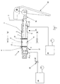
Figure 1 is an air spring pneumatic system according to the present invention with the cylinder piston rod retracted. -
Figure 2 is a cross sectional view of the cylinder ofFigure 1 taken along the line A-A inFigure 1 , showing the orientation of the exhaust vent hole. -
Figure 3 is the air spring pneumatic system ofFigure 1 with the cylinder piston rod extended. - An air spring ejector of the present invention is show in
Figure 1 . The ejector comprises an ejector device orfinger 18 activated by a pneumatic cylinder and piston arrangement. - The pneumatic system comprises a double acting air spring (pneumatic) cylinder 1 within which a
piston 8 moves. Ahigh pressure manifold 24 is connected to afirst cylinder port 19 at therear end 21 of the cylinder 1 via ahigh speed valve 22. Thehigh speed valve 22 may be for example a 3/2 or 5/2 electropneumatic valve. The pressure through thehigh pressure manifold 24 may be preset at a desired pressure suitably between 137,8 and 551,2 KPa (20 and 80 PSIG). - A
low pressure manifold 26 is connected to asecond cylinder port 23 at theleading end 25 of the cylinder 1. A suitable pressure through thelow pressure manifold 26 may be in the range from 68,9 to 206,7 KPa (10 to 30 PSIG). - The unit operates on the basis of the continuous application of a static pressure to one side of the double acting cylinder piston 8 (the leading side 9) and actuating the cylinder 1 by high speed sorter triggered application of higher pressure (> 68,9 KPa) (> 10PSIG) to the other side of the piston 8 (the rear side 11).
- Selective use of appropriate air pressures and actuation timing can permit in excess of 2000 ejections per minute. Repeatability is excellent with time differences between multiple ejectors being 0.5ms or less.
- A
vent hole 14 is provided on the barrel orcylinder wall 3 of the double acting cylinder 1.Fig 1 showsfirst chamber 6 andsecond chamber 4 which represent the spaces in the cylinder to the rear and front of thecylinder piston 8 respectively. Thevent hole 14 is located in thecylinder barrel 3 at a distance from the rear end of the cylinder. Thevent hole 14 acts as a quick exhaust port for thefirst chamber 6. - The rejector or paddle or
finger 18 is pivotally mounted at the end of thepiston rod 2. The paddle is pivotally connected to aclevis 16, which in turn is mounted at the free end of the piston rod. -
Figure 2 is a cross-section of the cylinder 1 taken along line A-A inFigure 1 . As shown inFigure 2 , thevent hole 14 at this distance along thebarrel 3 can be positioned at an angle from 0 to 180 deg from the vertical. The angle of 150 deg is preferred to allow a small portion of oil to remain in the first chamber to enhance cylinder lubrication. The venting may be achieved by a single hole or multiple annular orientated holes depending on the bore and stroke of the cylinder. - Designed into the
cylinder piston 8 is a novel double annular seal arrangement comprising afront piston ring 10 and arear piston ring 12. Thefront piston ring 10 is used to permanently seal thesecond chamber 4 and maintain this side of the cylinder 1 at the low pressure. Therear piston ring 12 is used to seal the first chamber and maintain this side of the cylinder 1 at the high pressure until the cylinder (piston)rod 2 reaches 50% of full extension. At this position therear piston ring 12 passes over thevent hole 14 instantly reducing the pressure in thefirst chamber 6. However, the momentum generated up to this stage carries thecylinder rod 2 /ejector 18 to full extension at high velocity, thereby completing actuation of the finger. - Normally in a double acting cylinder system, venting of this kind must occur back through the piping and valve system. This tends to produce a substantial time lag and thus longer cycle times. By addressing this time lag problem with larger valves and piping, other problems regarding repeatability and response time then become issues. With the above-mentioned feature of the quick venting at 50% from the end of the stroke, ambient pressure is achieved within
chamber 6 substantially instantaneously, thus eliminating time lag and reducing cycle times. Repeatability is also improved. -
Figure 3 shows the air spring pneumatic system ofFigure 1 with the cylinder extended. - The pneumatic rejector system of the present invention in use in an air spring cylinder cycle will now be described with reference to
Figures 1 and3 . - The
cylinder rod 2 andejector 18 are fully retracted (as perFigure 1 ). Thesecond chamber 4 is at low pressure (68,9 - 206,7 KPa) (10 - 30 PSIG) providing the retracting force and thefirst chamber 6 is at ambient pressure. - A signal is given by a detection device to eject. This is converted to an excitation of a high speed valve coil in the
high speed valve 22 which in turns opens the valve, simultaneously closing the valve'sexhaust port 20. Typical excitation times are 4 to 30ms. During excitation, air is allowed to pass from thehigh pressure manifold 24 tofirst chamber 6. As this pressure is 68,9 KPa (10 PSI) or more higher than that in thesecond chamber 4, the cylinder rod/ejector 18 immediately begins to outstroke. Thesecond chamber 4 pressure is held static, so that as the pressure in thefirst chamber 6 increases, the cylinder rod/ejector 18 acceleration increases, such that a substantially steady velocity is reached at less than 10% of stroke. - As the cylinder rod/
ejector 18 nears 50% of full extension the forward (front)piston ring 10 passes over thevent hole 14 on thecylinder barrel 3. This has the effect of rapidly depressurising thefirst chamber 6 and permits the cylinder rod/ejector 18 to decelerate. However the momentum already imparted to the cylinder rod/ejector 18 is such that it continues to the end of its stroke with a velocity substantially equal to that when it commenced venting. Very high speed outstroke times down to 5ms (half conventional) are achieved. Even though the cylinder is travelling at high velocity toward full stroke, thesecond chamber 4 is still at low pressure (68,9 - 206,7 KPa) (10 - 30 PSI) and so acts as an air cushion for thepiston 8. This dramatically reduces shock on the cylinder unit and the ejector mechanisms improving ejector lifetimes. - On most efficient ejection systems, the excitation time will have expired before the cylinder reaches full stroke. This is still the case with the air spring arrangement. When the high speed valve excitation time expires, the
first cylinder port 19 connecting to thehigh pressure manifold 24 is closed off, with simultaneous opening of the valve'sexhaust port 20. With thefirst chamber 6 now depressurised to ambient pressure, the static low pressure (68,9 - 206,7 KPa) (10 - 30 PSIG) of thesecond chamber 4 now immediately forces the cylinder rod/ejector 18 to retract. - For the first 50% of the return stroke the free air in the
first chamber 6 is expelled through thevent hole 14 permitting full pressure differential to operate, resulting in high speed retraction. For the last 50% of return stroke, the rear seal (piston ring 11) now passes back over thevent hole 14 and thus reseals thefirst chamber 6. All air trapped in thefirst chamber 6 is forced back through the piping and high speedvalve exhaust port 20. This air is at ambient pressure and so represents substantially less volume than a conventional system requires to expel through a valve exhaust port. Retraction is therefore at higher speed. Coupled to this is the fact that at near full retraction a small pressure (6,89 - 20,67 KPa) (1-3PSIG) has built up in thefirst chamber 6 creating a small air cushioning effect. This again reduces shock on the cylinder components and the ejector mechanics prolonging life. - The words "comprises/comprising" and the words "having/including" when used herein with reference to the present invention are used to specify the presence of stated features, integers, steps or components but does not preclude the presence or addition of one or more other features, integers, steps, components or groups thereof.
Claims (11)
- A double acting cylinder and piston mechanism comprising:a cylinder (1) substantially closed at both ends by front (5) and rear (7) end walls,a piston (8) axially displaceable within the cylinder (1),a first region (6) defined between the piston (8) and the rear end wall (7) of the cylinder (1) and a second region (4) defined between the piston (8) and the front end wall (5) of the cylinder (1),a piston rod (2) extending from the piston (8) through the front end wall (5) of the cylinder (1),an air inlet port (19) for communication with said first region (6) of the cylinder (1), andat least one exhaust vent (14) which is exposed during axial displacement of the piston (8) for release of air delivered to the first region (6) of the cylinder (1) through the air inlet port (19),characterised in that the piston (8) is of sufficient length to prevent communication between the second region (4) and the exhaust vent (14) so that a static air pressure may be maintained in the second region (4) of the cylinder (1) to cushion impact between the piston (8) and the front end wall (5) of the cylinder (1).
- A double acting cylinder and piston mechanism according to Claim 1, wherein the air inlet port (19) is at a first axial end region of the cylinder (1).
- A double acting cylinder and piston mechanism according to any preceding claim, wherein an axial displacement of the piston (8) is effected by a change in the differential pressures between the air in the first region (6) and the air in the second region (4) of the cylinder (1).
- A double acting cylinder and piston mechanism according to any preceding claim, further comprising sealing means (10, 12) between the piston (8) and the cylinder wall (3).
- A double acting cylinder and piston mechanism according to any preceding claim, wherein the sealing means (10, 12) comprises at least one piston ring (10, 12).
- A double acting cylinder and piston mechanism according to any preceding claim, wherein the exhaust vent (14) is defined in the cylinder wall (3).
- A double acting cylinder and piston mechanism according to claim 6, wherein, in a horizontal disposition of the cylinder (1), the exhaust vent (14) is located at a circumferential angular location relative to the lowermost longitudinal extent of the cylinder (1).
- A pneumatic product rejection system comprising the double acting cylinder and piston mechanism of any preceding claim.
- A pneumatic product rejection system according to Claim 8 further comprising:a high pressure manifold (24) in communication with the air inlet port (19),a low pressure manifold (26) in communication with the second region (4) in the cylinder (1),a control valve (22) between the high pressure manifold (24) and the air inlet port (19), anda paddle (18) mounted at the free end of the piston rod (2) for contacting and displacing from its path a product to be rejected.
- A pneumatic product rejection system according to Claim 9 wherein the paddle (18) is pivotally mounted at the free end of the piston rod (2).
- A pneumatic product rejection system according to any of Claims 8 to 10 comprising a multiplicity of paddles (18).
Priority Applications (7)
| Application Number | Priority Date | Filing Date | Title |
|---|---|---|---|
| AT04076688T ATE426745T1 (en) | 2004-06-09 | 2004-06-09 | PNEUMATIC SORTING SYSTEM FOR PRODUCTS WITH AIR SPRING |
| DE602004020196T DE602004020196D1 (en) | 2004-06-09 | 2004-06-09 | Pneumatic sorting system for products with air spring |
| ES04076688T ES2322586T3 (en) | 2004-06-09 | 2004-06-09 | PNEUMATIC SYSTEM FOR REJECTING PRODUCTS WITH AIR SHOCK ABSORBER. |
| PL04076688T PL1605170T3 (en) | 2004-06-09 | 2004-06-09 | An air spring pneumatic product rejection system |
| EP04076688A EP1605170B1 (en) | 2004-06-09 | 2004-06-09 | An air spring pneumatic product rejection system |
| US11/629,039 US8082838B2 (en) | 2004-06-09 | 2005-06-09 | Air spring pneumatic product rejection system |
| PCT/IE2005/000066 WO2005121565A1 (en) | 2004-06-09 | 2005-06-09 | An air spring pneumatic product rejection system |
Applications Claiming Priority (1)
| Application Number | Priority Date | Filing Date | Title |
|---|---|---|---|
| EP04076688A EP1605170B1 (en) | 2004-06-09 | 2004-06-09 | An air spring pneumatic product rejection system |
Publications (2)
| Publication Number | Publication Date |
|---|---|
| EP1605170A1 EP1605170A1 (en) | 2005-12-14 |
| EP1605170B1 true EP1605170B1 (en) | 2009-03-25 |
Family
ID=34928276
Family Applications (1)
| Application Number | Title | Priority Date | Filing Date |
|---|---|---|---|
| EP04076688A Expired - Lifetime EP1605170B1 (en) | 2004-06-09 | 2004-06-09 | An air spring pneumatic product rejection system |
Country Status (7)
| Country | Link |
|---|---|
| US (1) | US8082838B2 (en) |
| EP (1) | EP1605170B1 (en) |
| AT (1) | ATE426745T1 (en) |
| DE (1) | DE602004020196D1 (en) |
| ES (1) | ES2322586T3 (en) |
| PL (1) | PL1605170T3 (en) |
| WO (1) | WO2005121565A1 (en) |
Cited By (2)
| Publication number | Priority date | Publication date | Assignee | Title |
|---|---|---|---|---|
| DE102020002719A1 (en) | 2020-05-06 | 2021-11-11 | Wolfram Strothmann | Device and method for controllable, dynamic mechanical processing of objects with passively driven tools |
| DE102020002720A1 (en) | 2020-05-06 | 2021-11-11 | Wolfram Strothmann | Cylinder drive for executing highly dynamic linear strokes |
Families Citing this family (4)
| Publication number | Priority date | Publication date | Assignee | Title |
|---|---|---|---|---|
| IE20090111A1 (en) | 2009-02-11 | 2010-09-01 | Oseney Ltd | Combination air/mechanical rejection |
| US8561781B2 (en) * | 2010-12-15 | 2013-10-22 | Santa Rosa Systems, Llc | Diverter swing arm |
| DE102015117489A1 (en) | 2015-10-14 | 2017-04-20 | Wolfram Strothmann | Drive system for several actuators arranged in a row |
| CN107127167A (en) * | 2017-06-12 | 2017-09-05 | 合肥泰禾光电科技股份有限公司 | Device for eliminating and material separation device for material separation device |
Family Cites Families (9)
| Publication number | Priority date | Publication date | Assignee | Title |
|---|---|---|---|---|
| US3141381A (en) * | 1960-06-20 | 1964-07-21 | Nat Castings Co | Remote control apparatus |
| US3165981A (en) * | 1961-02-13 | 1965-01-19 | Amour Alessandro | Fluid actuated servo-control device |
| CH386855A (en) * | 1961-02-13 | 1965-01-15 | Amour Alessandro | Hydraulic servo control device |
| US3422948A (en) * | 1967-03-06 | 1969-01-21 | Conveyor Systems | Apparatus for discharging articles from a moving conveyor |
| US4099620A (en) | 1977-03-23 | 1978-07-11 | Acurex Corporation | Rejector drive system for sorting apparatus |
| FR2479918A1 (en) * | 1980-04-04 | 1981-10-09 | Climax France Sa | Linear actuator with variable force - uses differential piston heads to control force over most of travel |
| US4595091A (en) * | 1984-05-02 | 1986-06-17 | Pennwalt Corporation | Article diverter |
| DE3708989C2 (en) * | 1987-03-19 | 1993-10-14 | Festo Kg | Control device for a piston displaceable in a double-acting cylinder |
| DE4038380C1 (en) * | 1990-12-01 | 1991-11-28 | G.M. Pfaff Ag, 6750 Kaiserslautern, De | Activator mechanism for press element - includes pressurising cylinder to move element from outer work position to safe spacing with drive means |
-
2004
- 2004-06-09 PL PL04076688T patent/PL1605170T3/en unknown
- 2004-06-09 DE DE602004020196T patent/DE602004020196D1/en not_active Expired - Lifetime
- 2004-06-09 ES ES04076688T patent/ES2322586T3/en not_active Expired - Lifetime
- 2004-06-09 AT AT04076688T patent/ATE426745T1/en not_active IP Right Cessation
- 2004-06-09 EP EP04076688A patent/EP1605170B1/en not_active Expired - Lifetime
-
2005
- 2005-06-09 WO PCT/IE2005/000066 patent/WO2005121565A1/en not_active Ceased
- 2005-06-09 US US11/629,039 patent/US8082838B2/en active Active
Cited By (2)
| Publication number | Priority date | Publication date | Assignee | Title |
|---|---|---|---|---|
| DE102020002719A1 (en) | 2020-05-06 | 2021-11-11 | Wolfram Strothmann | Device and method for controllable, dynamic mechanical processing of objects with passively driven tools |
| DE102020002720A1 (en) | 2020-05-06 | 2021-11-11 | Wolfram Strothmann | Cylinder drive for executing highly dynamic linear strokes |
Also Published As
| Publication number | Publication date |
|---|---|
| EP1605170A1 (en) | 2005-12-14 |
| ATE426745T1 (en) | 2009-04-15 |
| DE602004020196D1 (en) | 2009-05-07 |
| WO2005121565A1 (en) | 2005-12-22 |
| US20090151553A1 (en) | 2009-06-18 |
| US8082838B2 (en) | 2011-12-27 |
| ES2322586T3 (en) | 2009-06-23 |
| PL1605170T3 (en) | 2009-08-31 |
Similar Documents
| Publication | Publication Date | Title |
|---|---|---|
| AU649768B2 (en) | A cyclic hydraulic actuator | |
| AU2004213190B2 (en) | Control valve in a percussion device and a method comprising a closed pressure space at the end position of the piston | |
| JP5509338B2 (en) | Multistage valve system | |
| GB2149014A (en) | Pneumatic cylinder having cushioning mechanism and method of cushioning the pneumatic cylinder | |
| EP1286814B1 (en) | Actuator having dual piston surfaces | |
| JP2001527196A (en) | Gear shifter | |
| EP0243407B1 (en) | Improvements to punch presses | |
| EP1605170A1 (en) | An air spring pneumatic product rejection system | |
| US6899206B2 (en) | Air cylinder with high frequency shock absorber and accelerator | |
| CN112431816A (en) | Tail end buffer device for controlling movement speed of hydraulic actuator cylinder by oil damping | |
| US3601987A (en) | Device for building-up fluid pressure pulses | |
| US3766830A (en) | Percussion apparatus | |
| EP3896293B1 (en) | Fluid pressure cylinder | |
| US4524660A (en) | Pneumatic-hydraulic driving device for the knockout mechanism associated with the slide of a press-machine | |
| US20030047335A1 (en) | Soft-touch pneumatic drive unit | |
| US5494078A (en) | Pneumatic lift device for dual flow valve | |
| US20150152896A1 (en) | Three-stage hydraulic actuator and method of operating the same | |
| US5383262A (en) | Blind riveting system | |
| NL8200157A (en) | DEVICE FOR SUPPLYING A COMPRESSIBLE DRIVE MEDIUM TO A MOVING AND WEATHER MOTOR. | |
| JP2987548B2 (en) | Cylinder control method and stop / start speed adjusting cylinder and valve | |
| CN1097177C (en) | Fluid-powered cylinder | |
| JP3615967B2 (en) | Hydraulic cylinder device | |
| KR101928728B1 (en) | Pneumatic device | |
| US20030070541A1 (en) | Variable-stroke pneumatic cylinder | |
| SU1292897A1 (en) | Cold header |
Legal Events
| Date | Code | Title | Description |
|---|---|---|---|
| PUAI | Public reference made under article 153(3) epc to a published international application that has entered the european phase |
Free format text: ORIGINAL CODE: 0009012 |
|
| AK | Designated contracting states |
Kind code of ref document: A1 Designated state(s): AT BE BG CH CY CZ DE DK EE ES FI FR GB GR HU IE IT LI LU MC NL PL PT RO SE SI SK TR |
|
| AX | Request for extension of the european patent |
Extension state: AL HR LT LV MK |
|
| 17P | Request for examination filed |
Effective date: 20060602 |
|
| AKX | Designation fees paid |
Designated state(s): AT BE BG CH CY CZ DE DK EE ES FI FR GB GR HU IE IT LI LU MC NL PL PT RO SE SI SK TR |
|
| 17Q | First examination report despatched |
Effective date: 20070108 |
|
| GRAP | Despatch of communication of intention to grant a patent |
Free format text: ORIGINAL CODE: EPIDOSNIGR1 |
|
| GRAS | Grant fee paid |
Free format text: ORIGINAL CODE: EPIDOSNIGR3 |
|
| GRAA | (expected) grant |
Free format text: ORIGINAL CODE: 0009210 |
|
| AK | Designated contracting states |
Kind code of ref document: B1 Designated state(s): AT BE BG CH CY CZ DE DK EE ES FI FR GB GR HU IE IT LI LU MC NL PL PT RO SE SI SK TR |
|
| REG | Reference to a national code |
Ref country code: GB Ref legal event code: FG4D |
|
| REG | Reference to a national code |
Ref country code: CH Ref legal event code: EP |
|
| REG | Reference to a national code |
Ref country code: IE Ref legal event code: FG4D |
|
| REF | Corresponds to: |
Ref document number: 602004020196 Country of ref document: DE Date of ref document: 20090507 Kind code of ref document: P |
|
| REG | Reference to a national code |
Ref country code: DE Ref legal event code: R096 Ref document number: 602004020196 Country of ref document: DE Effective date: 20090507 |
|
| REG | Reference to a national code |
Ref country code: ES Ref legal event code: FG2A Ref document number: 2322586 Country of ref document: ES Kind code of ref document: T3 |
|
| PG25 | Lapsed in a contracting state [announced via postgrant information from national office to epo] |
Ref country code: SI Free format text: LAPSE BECAUSE OF FAILURE TO SUBMIT A TRANSLATION OF THE DESCRIPTION OR TO PAY THE FEE WITHIN THE PRESCRIBED TIME-LIMIT Effective date: 20090325 Ref country code: FI Free format text: LAPSE BECAUSE OF FAILURE TO SUBMIT A TRANSLATION OF THE DESCRIPTION OR TO PAY THE FEE WITHIN THE PRESCRIBED TIME-LIMIT Effective date: 20090325 |
|
| PG25 | Lapsed in a contracting state [announced via postgrant information from national office to epo] |
Ref country code: AT Free format text: LAPSE BECAUSE OF FAILURE TO SUBMIT A TRANSLATION OF THE DESCRIPTION OR TO PAY THE FEE WITHIN THE PRESCRIBED TIME-LIMIT Effective date: 20090325 Ref country code: SE Free format text: LAPSE BECAUSE OF FAILURE TO SUBMIT A TRANSLATION OF THE DESCRIPTION OR TO PAY THE FEE WITHIN THE PRESCRIBED TIME-LIMIT Effective date: 20090625 |
|
| REG | Reference to a national code |
Ref country code: PL Ref legal event code: T3 |
|
| PG25 | Lapsed in a contracting state [announced via postgrant information from national office to epo] |
Ref country code: BE Free format text: LAPSE BECAUSE OF FAILURE TO SUBMIT A TRANSLATION OF THE DESCRIPTION OR TO PAY THE FEE WITHIN THE PRESCRIBED TIME-LIMIT Effective date: 20090325 |
|
| PG25 | Lapsed in a contracting state [announced via postgrant information from national office to epo] |
Ref country code: PT Free format text: LAPSE BECAUSE OF FAILURE TO SUBMIT A TRANSLATION OF THE DESCRIPTION OR TO PAY THE FEE WITHIN THE PRESCRIBED TIME-LIMIT Effective date: 20090901 Ref country code: CZ Free format text: LAPSE BECAUSE OF FAILURE TO SUBMIT A TRANSLATION OF THE DESCRIPTION OR TO PAY THE FEE WITHIN THE PRESCRIBED TIME-LIMIT Effective date: 20090325 Ref country code: EE Free format text: LAPSE BECAUSE OF FAILURE TO SUBMIT A TRANSLATION OF THE DESCRIPTION OR TO PAY THE FEE WITHIN THE PRESCRIBED TIME-LIMIT Effective date: 20090325 |
|
| PG25 | Lapsed in a contracting state [announced via postgrant information from national office to epo] |
Ref country code: RO Free format text: LAPSE BECAUSE OF FAILURE TO SUBMIT A TRANSLATION OF THE DESCRIPTION OR TO PAY THE FEE WITHIN THE PRESCRIBED TIME-LIMIT Effective date: 20090325 |
|
| PG25 | Lapsed in a contracting state [announced via postgrant information from national office to epo] |
Ref country code: DK Free format text: LAPSE BECAUSE OF FAILURE TO SUBMIT A TRANSLATION OF THE DESCRIPTION OR TO PAY THE FEE WITHIN THE PRESCRIBED TIME-LIMIT Effective date: 20090325 Ref country code: BG Free format text: LAPSE BECAUSE OF FAILURE TO SUBMIT A TRANSLATION OF THE DESCRIPTION OR TO PAY THE FEE WITHIN THE PRESCRIBED TIME-LIMIT Effective date: 20090625 Ref country code: MC Free format text: LAPSE BECAUSE OF NON-PAYMENT OF DUE FEES Effective date: 20090630 |
|
| PLBE | No opposition filed within time limit |
Free format text: ORIGINAL CODE: 0009261 |
|
| REG | Reference to a national code |
Ref country code: CH Ref legal event code: PL |
|
| STAA | Information on the status of an ep patent application or granted ep patent |
Free format text: STATUS: NO OPPOSITION FILED WITHIN TIME LIMIT |
|
| 26N | No opposition filed |
Effective date: 20091229 |
|
| REG | Reference to a national code |
Ref country code: DE Ref legal event code: R097 Ref document number: 602004020196 Country of ref document: DE Effective date: 20091229 |
|
| PG25 | Lapsed in a contracting state [announced via postgrant information from national office to epo] |
Ref country code: LI Free format text: LAPSE BECAUSE OF NON-PAYMENT OF DUE FEES Effective date: 20090630 Ref country code: CH Free format text: LAPSE BECAUSE OF NON-PAYMENT OF DUE FEES Effective date: 20090630 |
|
| PG25 | Lapsed in a contracting state [announced via postgrant information from national office to epo] |
Ref country code: GR Free format text: LAPSE BECAUSE OF FAILURE TO SUBMIT A TRANSLATION OF THE DESCRIPTION OR TO PAY THE FEE WITHIN THE PRESCRIBED TIME-LIMIT Effective date: 20090626 |
|
| PG25 | Lapsed in a contracting state [announced via postgrant information from national office to epo] |
Ref country code: LU Free format text: LAPSE BECAUSE OF NON-PAYMENT OF DUE FEES Effective date: 20090609 |
|
| PG25 | Lapsed in a contracting state [announced via postgrant information from national office to epo] |
Ref country code: HU Free format text: LAPSE BECAUSE OF FAILURE TO SUBMIT A TRANSLATION OF THE DESCRIPTION OR TO PAY THE FEE WITHIN THE PRESCRIBED TIME-LIMIT Effective date: 20090926 |
|
| PG25 | Lapsed in a contracting state [announced via postgrant information from national office to epo] |
Ref country code: TR Free format text: LAPSE BECAUSE OF FAILURE TO SUBMIT A TRANSLATION OF THE DESCRIPTION OR TO PAY THE FEE WITHIN THE PRESCRIBED TIME-LIMIT Effective date: 20090325 |
|
| PG25 | Lapsed in a contracting state [announced via postgrant information from national office to epo] |
Ref country code: CY Free format text: LAPSE BECAUSE OF FAILURE TO SUBMIT A TRANSLATION OF THE DESCRIPTION OR TO PAY THE FEE WITHIN THE PRESCRIBED TIME-LIMIT Effective date: 20090325 |
|
| REG | Reference to a national code |
Ref country code: GB Ref legal event code: 732E Free format text: REGISTERED BETWEEN 20120705 AND 20120711 |
|
| REG | Reference to a national code |
Ref country code: SK Ref legal event code: TE4A Ref document number: E 5571 Country of ref document: SK Owner name: OSENEY LIMITED, DUBLIN 2, IE Effective date: 20120712 Ref country code: SK Ref legal event code: PC4A Ref document number: E 5571 Country of ref document: SK Owner name: ODENBERG ENGINEERING LIMITED, DUBLIN 2, IE Free format text: FORMER OWNER: OSENEY LIMITED, DUBLIN 2, IE Effective date: 20120712 |
|
| REG | Reference to a national code |
Ref country code: DE Ref legal event code: R082 Ref document number: 602004020196 Country of ref document: DE Representative=s name: VON KREISLER SELTING WERNER, DE |
|
| REG | Reference to a national code |
Ref country code: ES Ref legal event code: PC2A Owner name: ODENBERG ENGINEERING LIMITED Effective date: 20120816 |
|
| REG | Reference to a national code |
Ref country code: DE Ref legal event code: R082 Ref document number: 602004020196 Country of ref document: DE Representative=s name: VON KREISLER SELTING WERNER, DE Effective date: 20120807 Ref country code: DE Ref legal event code: R081 Ref document number: 602004020196 Country of ref document: DE Owner name: ODENBERG ENGINEERING LIMITED, IE Free format text: FORMER OWNER: OSENEY LTD., DUBLIN, IE Effective date: 20120807 Ref country code: DE Ref legal event code: R082 Ref document number: 602004020196 Country of ref document: DE Representative=s name: VON KREISLER SELTING WERNER - PARTNERSCHAFT VO, DE Effective date: 20120807 Ref country code: DE Ref legal event code: R082 Ref document number: 602004020196 Country of ref document: DE Representative=s name: DOMPATENT VON KREISLER SELTING WERNER - PARTNE, DE Effective date: 20120807 |
|
| REG | Reference to a national code |
Ref country code: FR Ref legal event code: TP Owner name: ODENBERG ENGINEERING LIMITED, IE Effective date: 20120829 |
|
| REG | Reference to a national code |
Ref country code: NL Ref legal event code: SD Effective date: 20121008 |
|
| REG | Reference to a national code |
Ref country code: FR Ref legal event code: PLFP Year of fee payment: 12 |
|
| REG | Reference to a national code |
Ref country code: FR Ref legal event code: PLFP Year of fee payment: 13 |
|
| REG | Reference to a national code |
Ref country code: FR Ref legal event code: PLFP Year of fee payment: 14 |
|
| REG | Reference to a national code |
Ref country code: FR Ref legal event code: PLFP Year of fee payment: 15 |
|
| P01 | Opt-out of the competence of the unified patent court (upc) registered |
Effective date: 20230515 |
|
| PGFP | Annual fee paid to national office [announced via postgrant information from national office to epo] |
Ref country code: NL Payment date: 20230515 Year of fee payment: 20 Ref country code: IT Payment date: 20230510 Year of fee payment: 20 Ref country code: IE Payment date: 20230510 Year of fee payment: 20 Ref country code: FR Payment date: 20230523 Year of fee payment: 20 Ref country code: DE Payment date: 20230502 Year of fee payment: 20 |
|
| PGFP | Annual fee paid to national office [announced via postgrant information from national office to epo] |
Ref country code: SK Payment date: 20230512 Year of fee payment: 20 Ref country code: PL Payment date: 20230511 Year of fee payment: 20 |
|
| PGFP | Annual fee paid to national office [announced via postgrant information from national office to epo] |
Ref country code: GB Payment date: 20230504 Year of fee payment: 20 Ref country code: ES Payment date: 20230707 Year of fee payment: 20 |
|
| REG | Reference to a national code |
Ref country code: DE Ref legal event code: R071 Ref document number: 602004020196 Country of ref document: DE |
|
| REG | Reference to a national code |
Ref country code: NL Ref legal event code: MK Effective date: 20240608 |
|
| REG | Reference to a national code |
Ref country code: ES Ref legal event code: FD2A Effective date: 20240626 |
|
| PG25 | Lapsed in a contracting state [announced via postgrant information from national office to epo] |
Ref country code: GB Free format text: LAPSE BECAUSE OF EXPIRATION OF PROTECTION Effective date: 20240608 |
|
| PG25 | Lapsed in a contracting state [announced via postgrant information from national office to epo] |
Ref country code: ES Free format text: LAPSE BECAUSE OF EXPIRATION OF PROTECTION Effective date: 20240610 |
|
| PG25 | Lapsed in a contracting state [announced via postgrant information from national office to epo] |
Ref country code: SK Free format text: LAPSE BECAUSE OF EXPIRATION OF PROTECTION Effective date: 20240609 |
|
| PG25 | Lapsed in a contracting state [announced via postgrant information from national office to epo] |
Ref country code: SK Free format text: LAPSE BECAUSE OF EXPIRATION OF PROTECTION Effective date: 20240609 Ref country code: GB Free format text: LAPSE BECAUSE OF EXPIRATION OF PROTECTION Effective date: 20240608 Ref country code: ES Free format text: LAPSE BECAUSE OF EXPIRATION OF PROTECTION Effective date: 20240610 |
|
| PG25 | Lapsed in a contracting state [announced via postgrant information from national office to epo] |
Ref country code: IE Free format text: LAPSE BECAUSE OF EXPIRATION OF PROTECTION Effective date: 20240609 |
|
| PG25 | Lapsed in a contracting state [announced via postgrant information from national office to epo] |
Ref country code: IE Free format text: LAPSE BECAUSE OF EXPIRATION OF PROTECTION Effective date: 20240609 |