EP1605145A1 - Exhaust system of multi-cylinder internal combustion engine - Google Patents
Exhaust system of multi-cylinder internal combustion engine Download PDFInfo
- Publication number
- EP1605145A1 EP1605145A1 EP05010888A EP05010888A EP1605145A1 EP 1605145 A1 EP1605145 A1 EP 1605145A1 EP 05010888 A EP05010888 A EP 05010888A EP 05010888 A EP05010888 A EP 05010888A EP 1605145 A1 EP1605145 A1 EP 1605145A1
- Authority
- EP
- European Patent Office
- Prior art keywords
- upstream
- downstream
- exhaust
- passages
- main exhaust
- Prior art date
- Legal status (The legal status is an assumption and is not a legal conclusion. Google has not performed a legal analysis and makes no representation as to the accuracy of the status listed.)
- Granted
Links
Images








Classifications
-
- F—MECHANICAL ENGINEERING; LIGHTING; HEATING; WEAPONS; BLASTING
- F01—MACHINES OR ENGINES IN GENERAL; ENGINE PLANTS IN GENERAL; STEAM ENGINES
- F01N—GAS-FLOW SILENCERS OR EXHAUST APPARATUS FOR MACHINES OR ENGINES IN GENERAL; GAS-FLOW SILENCERS OR EXHAUST APPARATUS FOR INTERNAL-COMBUSTION ENGINES
- F01N3/00—Exhaust or silencing apparatus having means for purifying, rendering innocuous, or otherwise treating exhaust
- F01N3/08—Exhaust or silencing apparatus having means for purifying, rendering innocuous, or otherwise treating exhaust for rendering innocuous
- F01N3/10—Exhaust or silencing apparatus having means for purifying, rendering innocuous, or otherwise treating exhaust for rendering innocuous by thermal or catalytic conversion of noxious components of exhaust
- F01N3/18—Exhaust or silencing apparatus having means for purifying, rendering innocuous, or otherwise treating exhaust for rendering innocuous by thermal or catalytic conversion of noxious components of exhaust characterised by methods of operation; Control
- F01N3/20—Exhaust or silencing apparatus having means for purifying, rendering innocuous, or otherwise treating exhaust for rendering innocuous by thermal or catalytic conversion of noxious components of exhaust characterised by methods of operation; Control specially adapted for catalytic conversion
- F01N3/2053—By-passing catalytic reactors, e.g. to prevent overheating
-
- F—MECHANICAL ENGINEERING; LIGHTING; HEATING; WEAPONS; BLASTING
- F01—MACHINES OR ENGINES IN GENERAL; ENGINE PLANTS IN GENERAL; STEAM ENGINES
- F01N—GAS-FLOW SILENCERS OR EXHAUST APPARATUS FOR MACHINES OR ENGINES IN GENERAL; GAS-FLOW SILENCERS OR EXHAUST APPARATUS FOR INTERNAL-COMBUSTION ENGINES
- F01N13/00—Exhaust or silencing apparatus characterised by constructional features
- F01N13/009—Exhaust or silencing apparatus characterised by constructional features having two or more separate purifying devices arranged in series
-
- F—MECHANICAL ENGINEERING; LIGHTING; HEATING; WEAPONS; BLASTING
- F01—MACHINES OR ENGINES IN GENERAL; ENGINE PLANTS IN GENERAL; STEAM ENGINES
- F01N—GAS-FLOW SILENCERS OR EXHAUST APPARATUS FOR MACHINES OR ENGINES IN GENERAL; GAS-FLOW SILENCERS OR EXHAUST APPARATUS FOR INTERNAL-COMBUSTION ENGINES
- F01N13/00—Exhaust or silencing apparatus characterised by constructional features
- F01N13/009—Exhaust or silencing apparatus characterised by constructional features having two or more separate purifying devices arranged in series
- F01N13/0093—Exhaust or silencing apparatus characterised by constructional features having two or more separate purifying devices arranged in series the purifying devices are of the same type
-
- F—MECHANICAL ENGINEERING; LIGHTING; HEATING; WEAPONS; BLASTING
- F01—MACHINES OR ENGINES IN GENERAL; ENGINE PLANTS IN GENERAL; STEAM ENGINES
- F01N—GAS-FLOW SILENCERS OR EXHAUST APPARATUS FOR MACHINES OR ENGINES IN GENERAL; GAS-FLOW SILENCERS OR EXHAUST APPARATUS FOR INTERNAL-COMBUSTION ENGINES
- F01N13/00—Exhaust or silencing apparatus characterised by constructional features
- F01N13/08—Other arrangements or adaptations of exhaust conduits
- F01N13/10—Other arrangements or adaptations of exhaust conduits of exhaust manifolds
-
- F—MECHANICAL ENGINEERING; LIGHTING; HEATING; WEAPONS; BLASTING
- F01—MACHINES OR ENGINES IN GENERAL; ENGINE PLANTS IN GENERAL; STEAM ENGINES
- F01N—GAS-FLOW SILENCERS OR EXHAUST APPARATUS FOR MACHINES OR ENGINES IN GENERAL; GAS-FLOW SILENCERS OR EXHAUST APPARATUS FOR INTERNAL-COMBUSTION ENGINES
- F01N3/00—Exhaust or silencing apparatus having means for purifying, rendering innocuous, or otherwise treating exhaust
- F01N3/08—Exhaust or silencing apparatus having means for purifying, rendering innocuous, or otherwise treating exhaust for rendering innocuous
- F01N3/10—Exhaust or silencing apparatus having means for purifying, rendering innocuous, or otherwise treating exhaust for rendering innocuous by thermal or catalytic conversion of noxious components of exhaust
- F01N3/101—Three-way catalysts
-
- Y—GENERAL TAGGING OF NEW TECHNOLOGICAL DEVELOPMENTS; GENERAL TAGGING OF CROSS-SECTIONAL TECHNOLOGIES SPANNING OVER SEVERAL SECTIONS OF THE IPC; TECHNICAL SUBJECTS COVERED BY FORMER USPC CROSS-REFERENCE ART COLLECTIONS [XRACs] AND DIGESTS
- Y02—TECHNOLOGIES OR APPLICATIONS FOR MITIGATION OR ADAPTATION AGAINST CLIMATE CHANGE
- Y02T—CLIMATE CHANGE MITIGATION TECHNOLOGIES RELATED TO TRANSPORTATION
- Y02T10/00—Road transport of goods or passengers
- Y02T10/10—Internal combustion engine [ICE] based vehicles
- Y02T10/12—Improving ICE efficiencies
Definitions
- switch valves 4A and 4B are controlled by the actuator to take their close position blocking a fluid communication between each main exhaust passage 2 and corresponding intermediate main exhaust passage 3A or 3B, and at the same time, blocking a fluid communication between the two upstream main exhaust passages 2 which are joined.
- the exhaust gas led into EGR passage 20 is the gas that has been purified or cleaned by first catalyst part 18a of the auxiliary converter 18, the EGR system, particularly, the EGR gas control valve of the same can be protected from solid deposit and contamination.
- the sectional area of upstream bypass exhaust passage 11 should have a range that varies in accordance with an engine displacement. Examination has revealed that when the engine has a displacement of 2000cc, a sufficient performance is obtained from the bypass exhaust system with an inner diameter of upstream bypass exhaust passage 11 that ranges from 5mm to 15mm.
Landscapes
- Engineering & Computer Science (AREA)
- Chemical & Material Sciences (AREA)
- Combustion & Propulsion (AREA)
- Mechanical Engineering (AREA)
- General Engineering & Computer Science (AREA)
- Chemical Kinetics & Catalysis (AREA)
- Health & Medical Sciences (AREA)
- Toxicology (AREA)
- Materials Engineering (AREA)
- Exhaust Gas After Treatment (AREA)
- Exhaust Silencers (AREA)
Abstract
Description
- The present invention relates in general to exhaust systems of a multi-cylinder internal combustion engine, that have a catalytic converter for purifying the exhaust gas from the engine, and more particularly to the exhaust systems of a type that has main and auxiliary catalytic converters wherein when, like in a condition just after cold starting of the engine, the main catalytic converter is not sufficiently activated, the exhaust gas is led to the auxiliary catalytic converter that is easily activated.
- Usually, in motor vehicles powered by an internal combustion engine, the exhaust system of the engine is arranged beneath a floor of the vehicle and has a catalytic converter installed therein. If the catalytic converter is arranged in a relatively downstream position of the system, the converter takes a long time to be heated to a sufficient level for the gas purifying operation thereof particularly in a condition just after cold starting of the engine. That is, for such long time, the catalytic converter fails to exhibit its normal gas purifying work. However, if, for solving the above-mentioned drawback, the catalytic converter is arranged in a relatively upstream position of the system, that is, a position near the engine, another drawback tends to arise wherein due to attack of heat of the engine and the highly heated exhaust gas from the engine, the durability of the catalytic converter is lowered.
- In order to solve the above-mentioned drawbacks, various measures have been proposed, one of which is disclosed in Japanese Laid-open Patent Application (Tokkaihei) 5-321644. In this measure, a main passage extends from an exhaust manifold of the engine to a main catalytic converter. A bypass passage having an auxiliary catalytic converter installed therein extends from an upstream part of the main passage to a downstream part of the same. A switch valve is arranged at the upstream part of the main passage to open and close the main and bypass passages selectively, and a controller is connected to the switch valve. In operation, just after cold starting of the engine, the controller controls the switch valve to introduce the exhaust gas from the engine into the bypass passage.
- Since, in this measure, the auxiliary catalytic converter is positioned at a relatively upstream portion of the exhaust system, earlier activation of the auxiliary catalytic converter is expected, which induces earlier exhaust gas purifying work by the exhaust system.
- In the measure of the above-mentioned patent application publication, the gas inlet port of the bypass passage is positioned downstream of a branch junction portion of the exhaust manifold. That is, from a portion that is downstream of the junction portion where exhaust gas paths of all cylinders of the engine are joined, there extend the main and bypass passages in parallel. Thus, even though the auxiliary catalytic converter can take a more upstream position than the main catalytic converter, the distance from the exhaust port of each cylinder to the auxiliary catalytic converter can not be so short, and thus actually, the earlier exhaust gas purifying work in the cold starting of the engine is not effectively carried out.
- Because of branching of the bypass passage from the downstream position of the exhaust manifold, the exhaust manifold that has a marked thermal capacity causes the temperature of the exhaust gas led into the bypass passage to be lowered, which obstructs the earlier exhaust gas purifying work of the auxiliary catalytic converter.
- Furthermore, since the modernized exhaust manifolds are designed and constructed to avoid or at least minimize an exhaust interference, it is difficult to shorten the distance to the auxiliary catalytic converter from the inlet of the bypass passage. That is, in case of an exhaust manifold for in-line four cylinder engines, a so-called "4-2-1" connection type is currently employed wherein branches for #1 and #4 cylinders form one unit and braches for #2 and #3 cylinders form the other unit, and these two units are united at an outlet portion of the manifold. As is easily known, in this type exhaust manifold, it is difficult to reduce the overall length. The above-mentioned "4-2-1" connection type tends to have a complicated construction of the manifold, which increases the thermal capacity of the same.
- It is therefore an object of the present invention to provide an exhaust system of a multi-cylinder internal combustion engine, which is free of the above-mentioned drawbacks.
- In accordance with a first aspect of the present invention, there is provided an exhaust system of a multi-cylinder type internal combustion engine, which comprises a plurality of upstream main exhaust passages connected to cylinders of the engine respectively; a downstream main exhaust passage that is connected to the upstream main exhaust passages; a main catalytic converter mounted in the downstream main exhaust passage; a plurality of upstream bypass exhaust passages that extend from the upstream main exhaust passages respectively, each upstream bypass exhaust passage having a sectional area smaller than that of the corresponding upstream main exhaust passage; a downstream bypass exhaust passage that is connected to the upstream bypass exhaust passages; the downstream bypass exhaust passage having a downstream end connected to the downstream main exhaust passage at a position upstream of the main catalytic converter; an auxiliary catalytic converter mounted in the downstream bypass exhaust passage; and a gas flow switching device that is capable of forcing the exhaust gas from the cylinders of the engine to flow toward the upstream bypass exhaust passages when assuming a given operation position.
- In accordance with a second aspect of the present invention, there is provided an exhaust system of an in-line four cylinder internal combustion engine, which comprises first, second, third and fourth upstream main exhaust passages extending from first, second, third and fourth cylinders of the engine, the first and fourth cylinders being those whose firing order is not successive and the second and third cylinders being those whose firing order is not successive; a first intermediate main exhaust passage that is provided by joining downstream ends of the first and fourth upstream main exhaust passages; a second intermediate main exhaust passage that is provided by joining downstream ends of the second and third upstream main exhaust passages; a downstream main exhaust passage that is provided by joining downstream ends of the first and second intermediate main exhaust passages; a main catalytic converter mounted in the downstream main exhaust passage; first and second upstream bypass exhaust passages respectively extending from upstream portions of the first and second upstream main exhaust passages; third and fourth upstream bypass exhaust passages respectively extending from upstream portions of the third and fourth upstream main exhaust passages; a first intermediate bypass exhaust passage that is provided by jointing downstream ends of the first and second upstream bypass exhaust passages; a second intermediate bypass exhaust passage that is provided by joining downstream ends of the third and fourth upstream bypass exhaust passages; a downstream bypass exhaust passage that is provided by joining downstream ends of the first and second intermediate bypass exhaust passages, the downstream bypass exhaust passage having a downstream end connected to the downstream main exhaust passage at a position upstream of the main catalytic converter; and an auxiliary catalytic converter mounted in the downstream bypass exhaust passage.
- In accordance with a third aspect of the present invention, there is provided an exhaust system of an in-line four cylinder internal combustion engine, which comprises first, second, third and fourth upstream main exhaust passages extending from first, second, third and fourth cylinders of the engine, the first and fourth cylinders being those whose firing order is not successive and the second and third cylinders being those whose firing order is not successive; a first intermediate main exhaust passage that is provided by joining downstream ends of the first and fourth upstream main exhaust passages; a second intermediate main exhaust passage that is provided by joining downstream ends of the second and third upstream main exhaust passages; a downstream main exhaust passage that is provided by joining downstream ends of the first and second intermediate main exhaust passages; a main catalytic converter mounted in the downstream main exhaust passage; first and second upstream bypass exhaust passages respectively extending from upstream portions of the first and second upstream main exhaust passages; third and fourth upstream bypass exhaust passages respectively extending from upstream portions of the third and fourth upstream main exhaust passages; a first intermediate bypass exhaust passage that is provided by jointing downstream ends of the first and second upstream bypass exhaust passages; a second intermediate bypass exhaust passage that is provided by joining downstream ends of the third and fourth upstream bypass exhaust passages; a downstream bypass exhaust passage that is provided by joining downstream ends of the first and second intermediate bypass exhaust passages, the downstream bypass exhaust passage having a downstream end connected to the downstream main exhaust passage at a position upstream of the main catalytic converter; an auxiliary catalytic converter mounted in the downstream bypass exhaust passage; and switch valves respectively mounted in the first, second, third and fourth upstream main exhaust passages.
- Other objects and advantages of the present invention will become apparent from the following description when taken in conjunction with the accompanying drawings, in which:
- Fig. 1 is a conceptual drawing showing an exhaust system of a first embodiment of the present invention;
- Fig. 2 is a side view of the exhaust system of the first embodiment;
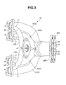
- Fig. 3 is a bottom view of an exhaust manifold employed in the first embodiment;
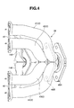
- Fig. 4 is a top view of the exhaust manifold employed in the first embodiment;
- Fig. 5 is an enlarged sectional view of a valve unit and its nearby portion;
- Fig. 6 is a front view of the valve unit;
- Fig. 7 is a view of a link mechanism for synchronously actuating two switch valves that constitute the valve unit;
- Fig. 8 is a sectional view of a valve unit employed in an exhaust system of a second embodiment of the present invention;
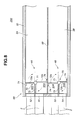
- Fig. 9 is a sectional view of a valve unit employed in an exhaust system of a third embodiment of the present invention;
- Fig. 10 is a sectional view of a valve unit employed in an exhaust system of a fourth embodiment of the present invention;
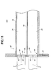
- Fig. 11 is a sectional view of a valve unit employed in an exhaust system of a first embodiment of the present invention;
- Fig. 12 is a view similar to Fig. 1, but showing an exhaust system of a sixth embodiment of the present invention;
- Fig. 13 is a sectional view of an essential portion of an exhaust system of a seventh embodiment of the present invention, in which an auxiliary catalytic converter is directly connected to a cylinder head of an engine; and
- Fig. 14 is a conceptional drawing showing an exhaust system of a seventh embodiment of the present invention.
-
- In the following, various embodiments of the present invention will be described in detail with reference to the accompanying drawings.
- For ease of understanding, various directional terms, such as, right, left, upper, lower, rightward and the like are used in the following description. However, these terms are to be understood with respect to only a drawing or drawings on which the corresponding part or portion is shown.
- Referring to Fig. 1, there is shown a conceptual drawing of an
exhaust system 100 of a first embodiment of the present invention. In this embodiment, an in-line four-cylinder internal combustion engine is employed for embodying the invention. - Four
cylinders 1, viz., #1, #2, #3 and #4 are aligned in a cylinder block of the engine. From eachcylinder 1, there extends an upstreammain exhaust passage 2. - It is to be noted that upstream
main exhaust passage 2 is a passage that extends from an exhaust valve (not shown) of the engine to a downstream part where an after-mentioned junction portion with the other upstreammain exhaust passage 2 is provided. - As shown, upstream
main exhaust passages 2 fromcylinders # 1 and #4 whose firing order is not successive are joined by a first intermediatemain exhaust passage 3A, and upstreammain exhaust passages 2 fromcylinders # 2 and #3 whose firing order is not successive are joined by a second intermediatemain exhaust passage 3B. - In each of the joined portions, there is installed a
switch valve switch valves - That is, when the engine is in a condition just after cold staring,
switch valves main exhaust passage 2 and corresponding intermediatemain exhaust passage main exhaust passages 2 which are joined. - As will be described in detail hereinafter, the two
switch valves valve unit 5A (see Figs. 2 and 5). - As is seen from Fig. 1, first and second intermediate
main exhaust passages valve unit 5 are joined at a junction portion 6 and a downstreammain exhaust passage 7 extends downstream from the junction portion 6. - In downstream
main exhaust passage 7, there is installed a maincatalytic converter 8 that includes a three-way catalyst and a HC (hydrocarbon) trapping catalyst. This maincatalytic converter 8 is arranged beneath a vehicle floor and has a sufficient capacity. - Thus, the four upstream
main exhaust passages 2, the two intermediatemain exhaust passages main exhaust passage 7 and the maincatalytic converter 8 constitute a main exhaust passage structure through which the exhaust gas from the engine is permitted to flow in a normal operation condition of the engine. That is, in such normal operation condition, the "4-2-1" connection type passage arrangement of the exhaust system is defined, and thus, the charging efficiency of the cylinders is increased with the aid of the exhaust dynamic effect. - As is seen from Fig. 1, from a
branched portion 12 of each upstreammain exhaust passage 2, there extends an upstreambypass exhaust passage 11. - It is to be noted that the
branched portion 12 is provided in thepassage 2 as upstream as possible. More specifically, the branchedportion 12 should be provided at least in a range that is upstream to a 1/2 point of the entire length of upstreammain exhaust passage 2. - Each upstream
bypass exhaust passage 11 has a sectional area that is sufficiently smaller than that of the corresponding upstreammain exhaust passage 2. - As shown, upstream
bypass exhaust passages 11 from themain exhaust passages 2 fromcylinders # 1 and #2 are united at ajunction portion 13, and a first intermediatebypass exhaust passage 14A extends downstream from thejunction portion 13. Similarly, upstreambypass exhaust passages 11 from themain exhaust passages 2 fromcylinders # 3 and #4 are joined at ajunction portion 13, and a second intermediatebypass exhaust passage 14B extends downstream from thejunction portion 13. Eachbypass exhaust passage 11 is made as short as possible. - As shown, the two intermediate
bypass exhaust passages 14A and14B are united at ajunction portion 15, and a downstreambypass exhaust passage 16 extends downstream fromjunction portion 15. The downstreambypass exhaust passage 16 is led to ajunction portion 17 provided on the downstreammain exhaust passage 7 at a position upstream of maincatalytic converter 8, as shown. - In downstream
bypass exhaust passage 16, there is installed an auxiliarycatalytic converter 18 that includes a three-way catalyst. This auxiliarycatalytic converter 18 is arranged in the bypass exhaust passage as upstream as possible. In other words, the length of each bypass exhaust passage betweenbranched portion 12 andjunction portion 15 should be made as short as possible. - If desired, the four upstream
bypass exhaust passages 11 may be joined at a position just upstream of auxiliarycatalytic converter 18 without the aid of the above-mentioned two intermediatebypass exhaust passages branched portion 12 and auxiliarycatalytic converter 18, the above-mentioned "4-2-1" united type passage arrangement is preferable in the present invention. That is, in this type, the entire length of the passages practically used can be reduced, and thus, the piping used can have a reduced thermal capacity and a reduced heat radiation area to the atmosphere. - As shown in Fig. 1, auxiliary
catalytic converter 18 comprises afirst catalyst part 18a and asecond catalyst part 18b which are arranged in tandem. Between these twoparts certain clearance 19 to which an inlet part of EGR (viz., exhaust gas recirculation)passage 20 is exposed. Although not shown in the drawing, an outlet part of thisEGR passage 20 is exposed to a part of an air intake system of the engine through an EGR control valve. That is, during operation of the engine, part of the exhaust gas is picked up from theclearance 19 and led to the air intake system. - It is to be noted that auxiliary
catalytic converter 18 has a small capacity as compared with maincatalytic converter 8, and is of a type that can exhibits a sufficient activation even in a relatively cold condition. - When, in operation, the engine is in a condition just after a cold staring, that is, when the temperature of the exhaust gas from the engine is not sufficiently high, the actuator (not shown) causes the two
switch valves bypass exhaust passages 11 from the branchedportions 12 and then led to auxiliarycatalytic converter 18 through the two intermediatebypass exhaust passages - Since auxiliary
catalytic converter 18 is positioned at the upstream side of the exhaust system, that is, near thecylinders # 1, #2, #3 and #4, and a smaller capacity, theconverter 18 is heated quickly and thus activated quickly, and thus a sufficient exhaust purifying operation of the auxiliarycatalytic converter 18 can start early. - Because, under this condition, each
switch valve main exhaust passages 2, undesired exhaust gas temperature reduction, that would be caused by a reciprocating movement of the exhaust gas between the paired upstreammain exhaust passages 2 through theswitch valve catalytic converter 18. - Furthermore, since, under this condition, the exhaust gas led into
EGR passage 20 is the gas that has been purified or cleaned byfirst catalyst part 18a of theauxiliary converter 18, the EGR system, particularly, the EGR gas control valve of the same can be protected from solid deposit and contamination. - While, when, due to continuous operation of the engine, the exhaust gas from the engine shows a sufficiently high temperature, the actuator causes the two
switch valves - With this, the exhaust gas from the engine is mainly led into the four upstream
main exhaust passages 2 and into the maincatalytic converter 8 through the paired intermediatemain exhaust passages bypass exhaust passage 11 has a cross sectional area that is smaller than that of the corresponding upstreammain exhaust passage 2, and because of presence of the auxiliarycatalytic converter 18 in the bypass exhaust system, almost all of the exhaust gas from the engine is forced to flow in the main exhaust system. Thus, in this case, the auxiliarycatalytic converter 18 is free of a thermal degradation. Furthermore, since the bypass exhaust passage is opened but in a small degree, a part of the exhaust gas is permitted to enter the bypass exhaust passage when, under a high speed and high load operation condition, a larger amount of exhaust gas is produced by the engine. This prevents lowering of charging efficiency of the cylinders caused by a back pressure. - As is described hereinabove, the main exhaust passage system is in the form of "4-2-1" united type arrangement, and thus, increase in the charging efficiency of the cylinders is achieved with the aid of the exhaust dynamic effect.
- While, the bypass exhaust passage system is arranged in the above-mentioned manner without taking the exhaust interference avoidance into a consideration. However, since each upstream
bypass exhaust passage 11 used has a sufficiently smaller sectional area, the exhaust interference inevitably induced by a communication with the corresponding cylinder can be reduced to a very small degree. If the sectional area of upstreambypass exhaust passage 11 is made larger than a predetermined high degree, a marked lowering of the charting efficiency would take place due to the exhaust interference. While, if the sectional area is made smaller than a predetermined low degree, the amount of exhaust gas during the time whenswitch valves - Thus, actually, the sectional area of upstream
bypass exhaust passage 11 should have a range that varies in accordance with an engine displacement. Examination has revealed that when the engine has a displacement of 2000cc, a sufficient performance is obtained from the bypass exhaust system with an inner diameter of upstreambypass exhaust passage 11 that ranges from 5mm to 15mm. - If operation of the EGR system is carried out under the open position of
switch valves catalytic converter 18. If, under this EGR operation, a part of the exhaust gas flowing in downstreammain exhaust passage 7 flows backward in downstreambypass exhaust passage 16, the exhaust gas in thepassage 16 is forced to pass throughsecond catalyst part 18b of theconverter 18, and thus, the exhaust gas used for the EGR system is not contaminated and thus, the EGR system, particularly, the EGR gas control valve is protected from solid deposit and contamination. The exhaust gas flowing backward in downwardbypass exhaust passage 16 is relatively slow in flow speed, and thus, the exhaust gas can stay insecond catalyst part 18b for a sufficient time. Thus,second catalyst part 18b may have a size or length smaller or shorter thanfirst catalyst part 18a, as shown. - In the following, detailed explanation on the
exhaust system 100 of the first embodiment will be made with reference to Fig. 2. - In the drawing, denoted by
numeral 31 is an internal combustion engine, which comprises acylinder block 32 and acylinder head 33 mounted oncylinder block 32. Theengine 31 is transversely mounted in an engine room of a motor vehicle. In the drawing, a right side ofengine 31 faces rearward of the vehicle, and thus, the right side will be referred to a back side in the following description. - An
exhaust manifold 34 is mounted to the back side ofcylinder head 33, that defines therein the above-mentioned four upstreammain exhaust passages 2. To a rear end ofexhaust manifold 34, there is mounted thevalve unit 5A that is equipped with the twoswitch valves valve unit 5A is afront exhaust tube 35 that constitutes the above-mentioned downstreammain exhaust passage 7. An upstream portion offront exhaust tube 35 has therein two parallel passages that constitute the above-mentioned intermediatemain exhaust passages catalytic converter 8 is mounted on thefront exhaust tube 35 at a position downstream of theparallel passages - As shown in Fig. 2, auxiliary
catalytic converter 18 and its associatedparts cylinder head 33 of theengine 31. Auxiliarycatalytic converter 18 is placed in the engine room in front offront exhaust tube 35. Thus, under running of the associated motor vehicle, auxiliarycatalytic converter 18 is effectively cooled by air flow that is produced when the vehicle runs, and thus, overheating of thisconverter 18 is suppressed. - As shown, each upstream
bypass exhaust passage 11 is branched at the branchedportion 12 from the corresponding upstreammain exhaust passage 2 in such a manner as to define an acute angle therebetween, which smoothes the gas flow from themain passage 2 to thebypass passage 11 at the time whenswitch valves bypass exhaust passages 11 are united to constitute the fist intermediatebypass exhaust passage 14A, and downstream portions of the other twobypass exhaust passages 11 are united to constitute the second intermediatebypass exhaust passage 14B. - The arrangement of the
exhaust system 100 of the first embodiment will be much clearly understood from Figs. 3 and 4 of the accompanying drawings. - Fig. 3 shows a bottom view of
exhaust manifold 34, and Fig. 4 shows a top view of the same. - As is seen from these drawings,
exhaust manifold 34 comprises fourbranches main exhaust passages 2 respectively, two mountingflanges branches bypass tubes 11 that extend from the upstream portions (12) of correspondingbranches bypass exhaust passages 11 respectively. - As shown, the two
bypass tubes 11 extending frombranches cylinders # 1 and #2 are united at their downstream portions to constitute a united passage portion that corresponds to the firstintermediate bypass passage 14A, and the other twobypass tubes 11 extending frombranches cylinders # 3 and #4 are united at their downstream portions to constitute another united passage portion that corresponds to the secondintermediate bypass passage 14B. - These two
united passage portions flange 47 that has an opening (no numeral) to which downstream ends of thepassage portions catalytic converter 18 is secured to mountingflange 47. - As will be understood from Figs. 3 and 4, at a downstream portion of four
branches exhaust manifold 34, there are provided two mountingflanges - As is seen from Fig. 3, mounting
flange 48A has two openings to whichbranches flange 48B has two openings to which theother branches flanges branches - Referring to Figs. 5 and 6, there is shown the detail of
valve unit 5A that is operatively connected to the two mountingflanges - As is well seen from Fig. 5,
valve unit 5A comprises acasing 51 that has four openings, which are a first pair ofopenings openings casing 51 with the two mountingflanges flange 48A are connected to the pairedopenings flange 48B are connected to the other pairedopenings - As is seen from Fig. 5 and as has been mentioned hereinabove, from
valve unit 5A, there extends thefront exhaust tube 35 that has at its upstream portion twoparallel passages main exhaust passages partition wall 59. One of the twoparallel passages openings parallel passages openings - Behind the paired
openings first switch valve 4A that comprises apivot shaft 56 actuated by an after-mentioned actuator, abody holder 57 integral withpivot shaft 56 and a flatrectangular valve body 58 fitted tobody holder 57. Similarly, behind the other pairedopenings second switch valve 4B that also comprises apivot shaft 56 actuated by the actuator, abody holder 57 integral withpivot shaft 56 and a flatrectangular valve body 58 fitted tobody holder 57. - Thus,
first switch valve 4A functions to selectively open and close the pairedopenings second switch valve 4B functions to selectively open and close the other pairedopenings first switch valve 4A functions to selectively open and close a communication between a group ofcylinders # 1 and #4 and onepassage 3A, andsecond switch valve 4B functions to selectively open and close a communication between the other group ofcylinders # 2 and #3 and theother passage 3B, as is understood from the drawing. - When
first switch valve 4A assumes the close position, a communication between the pairedopenings main exhaust passage 2 forcylinder # 1 andmain exhaust passage 2 forcylinder # 4 is blocked, and whensecond switch valve 4B assumes the close position, a communication between the pairedopenings main exhaust passage 2 forcylinder # 2 andmain exhaust passage 2 forcylinder # 3 is blocked. - When first and
second switch valves cylinders # 1 and #4 is led into first intermediatemain exhaust passage 3A, and at the same time, the exhaust gas fromcylinders # 2 and #3 is led into second intermediatemain exhaust passage 3B. - As will be described in detail hereinafter, a link mechanism actuated by the single actuator is arranged between the
respective pivot shafts 56 of first andsecond switch valves valves - Fig. 7 shows the detail of the link mechanism actuated by the
single actuator 64. The link mechanism comprises afirst link plate 61A fixed to pivotshaft 56 offirst switch valve 4A, asecond link plate 61B fixed to pivotshaft 56 ofsecond switch valve 4B, arod 62 having one end pivotally connected tofirst link plate 61A and the other end pivotally connected tosecond link plate 61B, and athird link plate 63 fixed to pivotshaft 56 offirst switch valve 4A. As shown, first andsecond link plates actuator 64 may be of a vacuum power type or an electromagnetic type, which has an output member connected tothird link plate 63 through arod 65. When theactuator 64 is energized, the output member of thesame pushes rod 65. With this,pivot shaft 56 offirst switch valve 4A is turned clockwise in Fig. 7 and at the sametime pivot shaft 56 ofsecond switch valve 4B is turned counterclockwise, and thus, first andsecond switch valves - Referring to Fig. 8, there is shown a
valve unit 5B that is installed in anexhaust system 200 of a second embodiment of the present invention. For easy understanding of this embodiment, the drawing is schematically illustrated with some illustration contradiction. -
Valve unit 5B employed in thisembodiment 200 has twobutterfly valves 70 for therespective switch valves - Each
butterfly valve 70 comprises apivot shaft 71 that is arranged at an upstream end portion of thecorresponding passage pivot shaft 71 has twoflat valve bodies flat valve bodies pivot shaft 71. - A
partition wall 73 extends axially in the upstream end portion of eachpassage corresponding pivot shaft 71, and thus the upstream end portion is divided into twopassages openings openings 53 and 54). -
Seal members 74 are secured to inner wall of eachpassage switch valve flat valve bodies passages valve body corresponding seal member 74. - That is, when
first switch valve 4A assumes the close position, the communication between each of the pairedopenings passage 3A is blocked and at the same time, the communication between the pairedopenings second switch valve 4B assumes the close position, the communication between each of the pairedopenings other passage 3B is blocked and at the same time, the communication between the pairedopenings pivot shafts 71 to synchronously actuate the same. - Referring to Fig. 9, there is shown a
valve unit 5C that is installed in anexhaust system 300 of a third embodiment of the present invention. Also, this drawing is schematically illustrated with some illustration contradiction for easy understanding of the embodiment. -
Valve unit 5C employed in thisembodiment 300 is substantially the same asvalve unit 5B of the above-mentionedembodiment 200, except that in thisthird embodiment 300, there is no means corresponding to partitionwalls 73 and in thisthird embodiment 300, twoflat valve bodies pivot shaft 71. Thus, in thisembodiment 300, even when eachswitch valve openings 52 and 55 (or 53 and 54) is kept unlike the case of the above-mentioned first andsecond embodiments - Referring to Fig. 10, there is shown a valve unit 5D that is installed in an
exhaust system 400 of a fourth embodiment of the present invention. Also, this drawing is schematically illustrated with some illustration contradition for easy understanding. - Valve unit 5D employed in this
embodiment 400 has only onebutterfly valve 80 that serves as both switchvalves main exhaust passages 2 and the two intermediatemain exhaust passages -
Butterfly valve 80 comprises apivot shaft 81 that is arranged at an upstream portion of the two intermediatemain exhaust passages pivot shaft 81 is rotatably supported by the axially extendingpartition wall 59.Pivot shaft 81 has twoflat valve bodies flat valve bodies pivot shaft 81, as shown. -
Seal members 84 are secured to inner walls of thepassages butterfly valve 80 takes its close position, the outside ends of twoflat valve bodies seal members 84. When turning in the direction of the arrows,butterfly valve 80 takes an open position. - As is understood from the drawing, when
butterfly valve 80 takes the close position, the fluid communication between the pairedopenings 52 and 55 (or 53 and 54) and first or second intermediatemain exhaust passage openings main exhaust passages 2 forcylinders # 1 and #4. While, whenbutterfly valve 80 turns to the open position, the fluid communication between the pairedopenings 52 and 55 (or 53 and 54) and first or second intermediatemain exhaust passage - Referring to Fig. 11, there is shown a
valve unit 5E that is employed in anexhaust system 500 of a fifth embodiment of the present invention. Like the above-mentioned drawings of Figs. 8 to 10, the drawing of this embodiment is schematically illustrated with some illustration contraction for easy understanding. -
Valve unit 5E employed in thisembodiment 500 uses two slidedoor type valves 90 asswitch valves door type valve 90 comprises aflat slide door 91 that is arranged behind the pairedopenings main exhaust passages - Referring to Fig. 12, there is shown an
exhaust system 600 of a sixth embodiment of the present invention. - As is seen from this drawing,
exhaust system 600 of this embodiment is similar toexhaust system 100 of the above-mentioned first embodiment. Thus, only parts or portions that are different from those of thefirst embodiment 100 will be described in detail in the following. - In this
sixth embodiment 600, aswitch valve 4 is installed in each of upstreammain exhaust passages 2. Eachswitch valve 4 is arranged in thecorresponding passage 2 as upstream as possible in order that the corresponding upstreambypass exhaust passage 11 can get a higher temperature exhaust gas after the cold starting of the engine. Actually, the fourbranches exhaust manifold 34 have a considerably higher thermal capacity, and thus, if the length of eachbranch corresponding switch valve 4 is large, the exhaust gas led to the correspondingbypass exhaust passage 11 is subjected to a marked temperature drop, which is undesirable to auxiliarycatalytic converter 18. - Referring to Figs. 13 and 14, there is schematically shown an
exhaust system 700 of a seventh embodiment of the present invention. In thisembodiment 700, auxiliarycatalytic converter 18 is directly connected tocylinder head 33 of theengine 31 in order to shorten the length of the fourbypass exhaust passages 11. As shown, in this case, fourbypass exhaust passages 11 are defined incylinder head 33, and eachbypass exhaust passage 11 is branched from the correspondingexhaust port 100 that constitutes part of upstreammain exhaust passage 2. - As is seen from Fig. 14, four
bypass exhaust passages 11 are joined at their downstream ends and directly connected to the inlet of auxiliarycatalytic converter 18. In this case, a much higher temperature exhaust gas can be led to theconverter 18 even just after cold staring of theengine 31. - Although, in the foregoing description, the present invention is described on the in-line four cylinder
internal combustion engine 31, the present invention is widely applicable to various types of multi-cylinder internal combustion engine including in-line type and V-type. - The entire contents of Japanese Patent Applications 2004-169394 filed June 8, 2004 and 2004-205357 filed July 13, 2004 are incorporated herein by reference.
- Although the invention has been described above with reference to the embodiments of the invention, the invention is not limited to such embodiments as described above. Various modifications and variations of such embodiments may be carried out by those skilled in the art, in light of the above description.
Claims (23)
- An exhaust system of a multi-cylinder type internal combustion engine, comprising:a plurality of upstream main exhaust passages (2) connected to cylinders of the engine respectively;a downstream main exhaust passage (7) that is connected to the upstream main exhaust passages (2);a main catalytic converter (8) mounted in the downstream main exhaust passage (7);a plurality of upstream bypass exhaust passages (11) that extend from the upstream main exhaust passages (2) respectively, each upstream bypass exhaust passage (11) having a sectional area smaller than that of the corresponding upstream main exhaust passage (2);a downstream bypass exhaust passage (16) that is connected to the upstream bypass exhaust passages (11); the downstream bypass exhaust passage (16) having a downstream end connected to the downstream main exhaust passage (7) at a position (17) upstream of the main catalytic converter (8);an auxiliary catalytic converter (18) mounted in the downstream bypass exhaust passage (16); anda gas flow switching device (5A, 5B, 5C, 5D, 5E) that is capable of forcing the exhaust gas from the cylinders of the engine to flow toward the upstream bypass exhaust passages (11) when assuming a given operation position.
- An exhaust system as claimed in Claim 1, in which the upstream bypass exhaust passages (11) extend from upstream portions (12) of the upstream main exhaust passages (2) respectively.
- An exhaust system as claimed in Claim 1, in which the downstream main exhaust passage (7) is provided by joining the upstream main exhaust passages (2) together.
- An exhaust system as claimed in Claim 1, in which the downstream bypass exhaust passage (16) is provided by joining the upstream bypass exhaust passages (11) together.
- An exhaust system as claimed in Claim 1, in which the gas flow switching device (5A, 5B, 5C, 5D, 5E) is arranged to selectively open and close a main exhaust passage way that includes the upstream main exhaust passages (2) and the downstream main exhaust passage (7).
- An exhaust system as claimed in Claim 5, in which the gas flow switching device (5A, 5B, 5C, 5D, 5E) comprises switch valves that are operatively mounted in the upstream main exhaust passages (2) respectively.
- An exhaust system as claimed in Claim 1, in which two of the upstream main exhaust passages (2) are united at their downstream ends to constitute an intermediate main exhaust passage (3A, 3B) that has a downstream end connected to an upstream end of the downstream main exhaust passage (7), and in which the two upstream main exhaust passages (2) are those extending from the cylinders (#1 and #4), (#2 and #3) whose firing order is not successive.
- An exhaust system as claimed in Claim 5, in which the gas flow switching device (5A, 5B, 5C, 5D, 5E) comprises a switch valve that is operatively installed in a portion where downstream ends of two of the upstream main exhaust passages (2) are joined together, the two upstream main exhaust passages (2) being those extending from the cylinders (#1 and #4), (#2 and #3) whose firing order is not successive.
- An exhaust system as claimed in Claim 8, in which the switch valve (5C, 5D) is arranged to open a fluid communication between the two upstream main exhaust passages (2) when the switch valve assumes its close position blocking a fluid communication between an upstream zone upstream of the switch valve and a downstream zone downstream of the switch valve.
- An exhaust system as claimed in Claim 8, in which the switch valve (5A, 5B, 5E) is arranged to block a fluid communication between the two upstream main exhaust passages (2) when the switch valve assumes its close position blocking a fluid communication between an upstream zone upstream of the switch valve and a downstream zone downstream of the switch valve.
- An exhaust system as claimed in Claim 10, in which the switch valve (5A) comprises a pivotal flat valve body (58) that is arranged to synchronously and selectively open and close a plurality mutually adjacent openings to which downstream ends of the upstream main exhaust passages (2) are connected.
- An exhaust system as claimed in Claim 10, in which the switch valve (5B) comprises a butterfly valve (70) that includes a pivot shaft (71) and two flat valve bodies (72a, 72b) that extend radially outward form the pivot shaft (71), the butterfly valve (70) being arranged to synchronously and selectively open and close two mutually adjacent openings to which downstream ends of two of the upstream main exhaust passages (2) are connected, the two upstream main exhaust passages (2) being those extending from the cylinders (#1 and #4), (#2 and #3) whose firing order is not successive.
- An exhaust system as claimed in Claim 1, further comprising:a first intermediate main exhaust passage (3A) that is arranged between a junction portion of downstream ends of two upstream main exhaust passages (2) and an upstream end of the downstream main exhaust passage (7), the two upstream main exhaust passages (2) being those extending from the cylinders (#1 and #4) whose firing order is not successive, anda second intermediate main exhaust passage (3B) that is arranged between a junction portion of downstream ends of the other two upstream main exhaust passages (2) and the upstream end of the downstream main exhaust passage (7), the other two upstream main exhaust passages (2) being those extending from the cylinders (#2 and #3) whose firing order is not successive.
- An exhaust system as claimed in Claim 1, in which each of the upstream main exhaust passages (2) comprises an exhaust port (100) defined in a cylinder head (33) of the engine (31) and in which each of the upstream bypass exhaust passages (11) extends through the cylinder head (33) to connect to the exhaust port (100).
- An exhaust system as claimed in Claim 1, in which the upstream main exhaust passages (2) comprise branches of an exhaust manifold (34), and in which the upstream bypass exhaust passages (11) have upstream ends exposed to upstream portions of the branches of the exhaust manifold (34) respectively.
- An exhaust system as claimed in Claim 1, in which each of the upstream bypass exhaust passages (11) is branched from the corresponding upstream main exhaust passage (2) in a manner to define an actuate angle therebetween thereby to smooth the exhaust gas flow from the main exhaust passage (2) to the bypass exhaust passage (11).
- An exhaust system as claimed in Claim 1, in which each of the upstream bypass exhaust passages (11) has a sectional area smaller than that of the corresponding upstream bypass exhaust passage (2) thereby to reduce an exhaust interference which would occur when the cylinders are communicated with one another.
- An exhaust system of an in-line four cylinder internal combustion engine, comprising:first, second, third and fourth upstream main exhaust passages (2) extending from first, second, third and fourth cylinders (#1, #2, #3 and #4) of the engine, the first and fourth cylinders being those whose firing order is not successive and the second and third cylinders being those whose firing order is not successive;a first intermediate main exhaust passage (3A) that is provided by joining downstream ends of the first and fourth upstream main exhaust passages (2);a second intermediate main exhaust passage (3B) that is provided by joining downstream ends of the second and third upstream main exhaust passages (2);a downstream main exhaust passage (7) that is provided by joining downstream ends of the first and second intermediate main exhaust passages (3A, 3B);a main catalytic converter (8) mounted in the downstream main exhaust passage (7);first and second upstream bypass exhaust passages (11) respectively extending from upstream portions of the first and second upstream main exhaust passages (2);third and fourth upstream bypass exhaust passages (11) respectively extending from upstream portions of the third and fourth upstream main exhaust passages (2);a first intermediate bypass exhaust passage (14A) that is provided by jointing downstream ends of the first and second upstream bypass exhaust passages (11);a second intermediate bypass exhaust passage (14B) that is provided by joining downstream ends of the third and fourth upstream bypass exhaust passages (11);a downstream bypass exhaust passage (16) that is provided by joining downstream ends of the first and second intermediate bypass exhaust passages (14A, 14B), the downstream bypass exhaust passage (16) having a downstream end connected to the downstream main exhaust passage (7) at a position upstream of the main catalytic converter (8); andan auxiliary catalytic converter (18) mounted in the downstream bypass exhaust passage (16).
- An exhaust system as claimed in Claim 18, further comprising:a first switch valve (4A) that selectively opens and closes a fluid communication between each of the first and fourth upstream main exhaust passages (2) and the first intermediate main exhaust passage (3A); anda second switch valve (4B) that selectively opens and closes a fluid communication between each of the second and third upstream main exhaust passages (2) and the second intermediate exhaust passage (3B).
- An exhaust system as claimed in Claim 15, in which the first and second switch valves (4A, 4B) are integrally mounted in a valve unit (5A, 5B, 5C, 5D, 5E).
- An exhaust system as claimed in Claim 20, in which an inlet opening of an exhaust gas recirculation system is exposed to an interior of the auxiliary catalytic converter to introduce thereinto the gas flowing in the auxiliary catalytic converter.
- An exhaust system of an in-line four cylinder internal combustion engine, comprising:first, second, third and fourth upstream main exhaust passages (2) extending from first, second, third and fourth cylinders (#1, #2, #3 and #4) of the engine, the first and fourth cylinders being those whose firing order is not successive and the second and third cylinders being those whose firing order is not successive;a first intermediate main exhaust passage (3A) that is provided by joining downstream ends of the first and fourth upstream main exhaust passages (2);a second intermediate main exhaust passage (3B) that is provided by joining downstream ends of the second and third upstream main exhaust passages (2);a downstream main exhaust passage (7) that is provided by joining downstream ends of the first and second intermediate main exhaust passages (3A, 3B);a main catalytic converter (8) mounted in the downstream main exhaust passage (7);first and second upstream bypass exhaust passages (11) respectively extending from upstream portions of the first and second upstream main exhaust passages (2);third and fourth upstream bypass exhaust passages (11) respectively extending from upstream portions of the third and fourth upstream main exhaust passages (2);a first intermediate bypass exhaust passage (14A) that is provided by jointing downstream ends of the first and second upstream bypass exhaust passages (11);a second intermediate bypass exhaust passage (14B) that is provided by joining downstream ends of the third and fourth upstream bypass exhaust passages (11);a downstream bypass exhaust passage (16) that is provided by joining downstream ends of the first and second intermediate bypass exhaust passages (14A, 14B), the downstream bypass exhaust passage (16) having a downstream end connected to the downstream main exhaust passage (7) at a position upstream of the main catalytic converter (8);an auxiliary catalytic converter (18) mounted in the downstream bypass exhaust passage (16); andswitch valves respectively mounted in the first, second, third and fourth upstream main exhaust passages (2).
- An exhaust system as claimed in Claim 22, in which an inlet opening of an exhaust gas recirculation system is exposed to an interior of the auxiliary catalytic converter to introduce thereinto the gas flowing in the auxiliary catalytic converter.
Applications Claiming Priority (4)
| Application Number | Priority Date | Filing Date | Title |
|---|---|---|---|
| JP2004169394A JP4400320B2 (en) | 2004-06-08 | 2004-06-08 | Exhaust device for multi-cylinder internal combustion engine |
| JP2004169394 | 2004-06-08 | ||
| JP2004205357A JP4400351B2 (en) | 2004-07-13 | 2004-07-13 | Exhaust device for multi-cylinder internal combustion engine |
| JP2004205357 | 2004-07-13 |
Publications (2)
| Publication Number | Publication Date |
|---|---|
| EP1605145A1 true EP1605145A1 (en) | 2005-12-14 |
| EP1605145B1 EP1605145B1 (en) | 2011-08-24 |
Family
ID=34936708
Family Applications (1)
| Application Number | Title | Priority Date | Filing Date |
|---|---|---|---|
| EP05010888A Expired - Lifetime EP1605145B1 (en) | 2004-06-08 | 2005-05-19 | Exhaust system of multi-cylinder internal combustion engine |
Country Status (2)
| Country | Link |
|---|---|
| US (1) | US7726119B2 (en) |
| EP (1) | EP1605145B1 (en) |
Cited By (5)
| Publication number | Priority date | Publication date | Assignee | Title |
|---|---|---|---|---|
| GB2423338A (en) * | 2005-02-17 | 2006-08-23 | Aisin Takaoka Co Ltd | Exhaust manifold with independent pipes in a pipe collection section |
| EP1710408A1 (en) * | 2005-04-08 | 2006-10-11 | Nissan Motor Co., Ltd. | Exhaust system for an internal combustion engine |
| EP1752634A1 (en) * | 2005-08-11 | 2007-02-14 | Nissan Motor Company Limited | Exhaust system |
| US7845161B2 (en) | 2006-05-29 | 2010-12-07 | Nissan Motor Co., Ltd. | Internal combustion engine and control method for internal combustion engine |
| DE102011114305A1 (en) * | 2011-09-23 | 2013-03-28 | Audi Ag | Internal combustion engine and method for operating an internal combustion engine |
Families Citing this family (6)
| Publication number | Priority date | Publication date | Assignee | Title |
|---|---|---|---|---|
| JP4901163B2 (en) * | 2005-09-06 | 2012-03-21 | ヤマハ発動機株式会社 | engine |
| JP4803059B2 (en) * | 2007-02-07 | 2011-10-26 | トヨタ自動車株式会社 | Cylinder head of internal combustion engine |
| KR20100136489A (en) * | 2008-03-31 | 2010-12-28 | 보르그워너 인코퍼레이티드 | Multi-port valve |
| JP5515977B2 (en) * | 2010-03-31 | 2014-06-11 | マツダ株式会社 | Exhaust system for multi-cylinder engine |
| FR2983532B1 (en) * | 2011-12-01 | 2015-02-13 | Valeo Sys Controle Moteur Sas | VALVE FOR A GAS CIRCUIT CIRCUIT IN A VEHICLE |
| CN103244250A (en) * | 2013-05-27 | 2013-08-14 | 奇瑞汽车股份有限公司 | VVT (variable valve timing) engine exhaust manifold |
Citations (5)
| Publication number | Priority date | Publication date | Assignee | Title |
|---|---|---|---|---|
| JPH05321644A (en) | 1992-05-26 | 1993-12-07 | Honda Motor Co Ltd | Engine exhaust purification device |
| US5277026A (en) * | 1992-02-22 | 1994-01-11 | Mercedes-Benz Ag | Internal combustion engine exhaust system |
| EP0584350A1 (en) * | 1992-03-10 | 1994-03-02 | Inst Francais Du Petrole | Two stroke internal combustion engine exhaust line. |
| EP1188909A2 (en) * | 2000-09-15 | 2002-03-20 | FERRARI S.p.A. | Internal combustion engine exhaust device |
| DE10151530A1 (en) * | 2001-10-18 | 2003-04-30 | Fev Motorentech Gmbh | Exhaust system, for a high-power four-stroke IC motor, has paired cylinders each with two outlet valves linked to an exhaust outflow and to a reflection unit connected to a second exhaust outflow |
Family Cites Families (9)
| Publication number | Priority date | Publication date | Assignee | Title |
|---|---|---|---|---|
| JPH07111136B2 (en) | 1989-02-08 | 1995-11-29 | 日産自動車株式会社 | Exhaust device for internal combustion engine |
| JPH0383315U (en) | 1989-12-18 | 1991-08-23 | ||
| JPH0722016A (en) | 1993-07-06 | 1995-01-24 | Matsushita Electric Ind Co Ltd | Battery pack |
| JPH0777034A (en) | 1993-09-09 | 1995-03-20 | Toyota Motor Corp | Exhaust device for internal combustion engine |
| JPH0722016U (en) * | 1993-09-22 | 1995-04-21 | 日産自動車株式会社 | Exhaust gas purification device for internal combustion engine |
| JP3264226B2 (en) | 1997-08-25 | 2002-03-11 | トヨタ自動車株式会社 | Exhaust gas purification device for internal combustion engine |
| JPH11343835A (en) * | 1998-06-01 | 1999-12-14 | Yamaha Motor Co Ltd | Exhaust system for internal combustion engine |
| JP2002213236A (en) | 2001-01-12 | 2002-07-31 | Fuji Heavy Ind Ltd | Exhaust system for turbocharged engine |
| JP3083315U (en) | 2001-07-10 | 2002-01-25 | 精三 岩山 | Chopping board with table |
-
2005
- 2005-05-19 EP EP05010888A patent/EP1605145B1/en not_active Expired - Lifetime
- 2005-06-07 US US11/145,962 patent/US7726119B2/en not_active Expired - Fee Related
Patent Citations (5)
| Publication number | Priority date | Publication date | Assignee | Title |
|---|---|---|---|---|
| US5277026A (en) * | 1992-02-22 | 1994-01-11 | Mercedes-Benz Ag | Internal combustion engine exhaust system |
| EP0584350A1 (en) * | 1992-03-10 | 1994-03-02 | Inst Francais Du Petrole | Two stroke internal combustion engine exhaust line. |
| JPH05321644A (en) | 1992-05-26 | 1993-12-07 | Honda Motor Co Ltd | Engine exhaust purification device |
| EP1188909A2 (en) * | 2000-09-15 | 2002-03-20 | FERRARI S.p.A. | Internal combustion engine exhaust device |
| DE10151530A1 (en) * | 2001-10-18 | 2003-04-30 | Fev Motorentech Gmbh | Exhaust system, for a high-power four-stroke IC motor, has paired cylinders each with two outlet valves linked to an exhaust outflow and to a reflection unit connected to a second exhaust outflow |
Cited By (10)
| Publication number | Priority date | Publication date | Assignee | Title |
|---|---|---|---|---|
| GB2423338A (en) * | 2005-02-17 | 2006-08-23 | Aisin Takaoka Co Ltd | Exhaust manifold with independent pipes in a pipe collection section |
| GB2423338B (en) * | 2005-02-17 | 2007-05-30 | Aisin Takaoka Co Ltd | Exhaust manifold |
| US7325396B2 (en) | 2005-02-17 | 2008-02-05 | Aisin Takaoka Co., Ltd. | Exhaust manifold |
| EP1710408A1 (en) * | 2005-04-08 | 2006-10-11 | Nissan Motor Co., Ltd. | Exhaust system for an internal combustion engine |
| US7441400B2 (en) | 2005-04-08 | 2008-10-28 | Nissan Motor Co., Ltd. | Exhaust system for an internal combustion engine |
| EP1752634A1 (en) * | 2005-08-11 | 2007-02-14 | Nissan Motor Company Limited | Exhaust system |
| US7559196B2 (en) | 2005-08-11 | 2009-07-14 | Nissan Motor Co., Ltd. | Exhaust system of an internal combustion engine |
| US7845161B2 (en) | 2006-05-29 | 2010-12-07 | Nissan Motor Co., Ltd. | Internal combustion engine and control method for internal combustion engine |
| DE102011114305A1 (en) * | 2011-09-23 | 2013-03-28 | Audi Ag | Internal combustion engine and method for operating an internal combustion engine |
| US9228544B2 (en) | 2011-09-23 | 2016-01-05 | Audi Ag | Internal combustion engine and method for operating an internal combustion engine |
Also Published As
| Publication number | Publication date |
|---|---|
| US20050268600A1 (en) | 2005-12-08 |
| EP1605145B1 (en) | 2011-08-24 |
| US7726119B2 (en) | 2010-06-01 |
Similar Documents
| Publication | Publication Date | Title |
|---|---|---|
| US7509800B2 (en) | Exhaust system of multi-cylinder internal combustion engine | |
| US7958874B2 (en) | Exhaust gas recirculation apparatus | |
| CN102713195B (en) | The turbosupercharger of direct UNICOM | |
| JP4553023B2 (en) | Exhaust gas switching valve | |
| US7726119B2 (en) | Exhaust system of multi-cylinder internal combustion engine | |
| JP2011099375A (en) | Exhaust reflux device of internal combustion engine | |
| CN105102801A (en) | Low pressure exhaust gas recirculation module cross-reference to related applications | |
| US20020100273A1 (en) | Exhaust system of an internal combustion engine | |
| CN100445523C (en) | Exhaust system of multi-cylinder internal combustion engine | |
| CN101326068A (en) | Internal combustion engine with turbocharger | |
| JP5909938B2 (en) | Intake and exhaust system for multi-cylinder engine | |
| CN113494394B (en) | EGR system of engine | |
| JPH0574688B2 (en) | ||
| CN108343515A (en) | Temperature control throttle valve device | |
| JP5168268B2 (en) | Exhaust gas recirculation device for internal combustion engine | |
| JP4325565B2 (en) | Exhaust gas purification device and exhaust gas purification method for internal combustion engine | |
| JP4591270B2 (en) | Exhaust device for internal combustion engine | |
| JPH04194310A (en) | Exhaust device for internal combustion engine | |
| CN110905700B (en) | Engine system | |
| US20220325660A1 (en) | Turbocharger system with turbine bypass circuit to reduce emissions during engine cold start | |
| JP4400351B2 (en) | Exhaust device for multi-cylinder internal combustion engine | |
| WO2011005560A2 (en) | Engine breathing system, components and method thereof | |
| JPH0732923Y2 (en) | Exhaust brake device | |
| JP2024093570A (en) | Exhaust heat recovery device | |
| JPH07180542A (en) | Engine exhaust purification device |
Legal Events
| Date | Code | Title | Description |
|---|---|---|---|
| PUAI | Public reference made under article 153(3) epc to a published international application that has entered the european phase |
Free format text: ORIGINAL CODE: 0009012 |
|
| 17P | Request for examination filed |
Effective date: 20050519 |
|
| AK | Designated contracting states |
Kind code of ref document: A1 Designated state(s): AT BE BG CH CY CZ DE DK EE ES FI FR GB GR HU IE IS IT LI LT LU MC NL PL PT RO SE SI SK TR |
|
| AX | Request for extension of the european patent |
Extension state: AL BA HR LV MK YU |
|
| 17Q | First examination report despatched |
Effective date: 20060720 |
|
| AKX | Designation fees paid |
Designated state(s): DE FR GB |
|
| RIC1 | Information provided on ipc code assigned before grant |
Ipc: F01N 3/20 20060101AFI20101115BHEP Ipc: F01N 13/10 20100101ALI20101115BHEP |
|
| GRAP | Despatch of communication of intention to grant a patent |
Free format text: ORIGINAL CODE: EPIDOSNIGR1 |
|
| GRAS | Grant fee paid |
Free format text: ORIGINAL CODE: EPIDOSNIGR3 |
|
| GRAA | (expected) grant |
Free format text: ORIGINAL CODE: 0009210 |
|
| AK | Designated contracting states |
Kind code of ref document: B1 Designated state(s): DE FR GB |
|
| REG | Reference to a national code |
Ref country code: GB Ref legal event code: FG4D |
|
| REG | Reference to a national code |
Ref country code: DE Ref legal event code: R096 Ref document number: 602005029661 Country of ref document: DE Effective date: 20111027 |
|
| PLBE | No opposition filed within time limit |
Free format text: ORIGINAL CODE: 0009261 |
|
| STAA | Information on the status of an ep patent application or granted ep patent |
Free format text: STATUS: NO OPPOSITION FILED WITHIN TIME LIMIT |
|
| 26N | No opposition filed |
Effective date: 20120525 |
|
| REG | Reference to a national code |
Ref country code: DE Ref legal event code: R097 Ref document number: 602005029661 Country of ref document: DE Effective date: 20120525 |
|
| PGFP | Annual fee paid to national office [announced via postgrant information from national office to epo] |
Ref country code: DE Payment date: 20130515 Year of fee payment: 9 Ref country code: GB Payment date: 20130515 Year of fee payment: 9 |
|
| PGFP | Annual fee paid to national office [announced via postgrant information from national office to epo] |
Ref country code: FR Payment date: 20130531 Year of fee payment: 9 |
|
| REG | Reference to a national code |
Ref country code: DE Ref legal event code: R119 Ref document number: 602005029661 Country of ref document: DE |
|
| GBPC | Gb: european patent ceased through non-payment of renewal fee |
Effective date: 20140519 |
|
| REG | Reference to a national code |
Ref country code: FR Ref legal event code: ST Effective date: 20150130 |
|
| REG | Reference to a national code |
Ref country code: DE Ref legal event code: R119 Ref document number: 602005029661 Country of ref document: DE Effective date: 20141202 |
|
| PG25 | Lapsed in a contracting state [announced via postgrant information from national office to epo] |
Ref country code: DE Free format text: LAPSE BECAUSE OF NON-PAYMENT OF DUE FEES Effective date: 20141202 |
|
| PG25 | Lapsed in a contracting state [announced via postgrant information from national office to epo] |
Ref country code: GB Free format text: LAPSE BECAUSE OF NON-PAYMENT OF DUE FEES Effective date: 20140519 Ref country code: FR Free format text: LAPSE BECAUSE OF NON-PAYMENT OF DUE FEES Effective date: 20140602 |