EP1605134A2 - Device for balancing a gas turbine rotor and gas turbine engine comprising such a device - Google Patents
Device for balancing a gas turbine rotor and gas turbine engine comprising such a device Download PDFInfo
- Publication number
- EP1605134A2 EP1605134A2 EP05253066A EP05253066A EP1605134A2 EP 1605134 A2 EP1605134 A2 EP 1605134A2 EP 05253066 A EP05253066 A EP 05253066A EP 05253066 A EP05253066 A EP 05253066A EP 1605134 A2 EP1605134 A2 EP 1605134A2
- Authority
- EP
- European Patent Office
- Prior art keywords
- clip
- tip shroud
- balance
- balance clip
- leading
- Prior art date
- Legal status (The legal status is an assumption and is not a legal conclusion. Google has not performed a legal analysis and makes no representation as to the accuracy of the status listed.)
- Granted
Links
Images




Classifications
-
- F—MECHANICAL ENGINEERING; LIGHTING; HEATING; WEAPONS; BLASTING
- F01—MACHINES OR ENGINES IN GENERAL; ENGINE PLANTS IN GENERAL; STEAM ENGINES
- F01D—NON-POSITIVE DISPLACEMENT MACHINES OR ENGINES, e.g. STEAM TURBINES
- F01D5/00—Blades; Blade-carrying members; Heating, heat-insulating, cooling or antivibration means on the blades or the members
- F01D5/02—Blade-carrying members, e.g. rotors
- F01D5/027—Arrangements for balancing
-
- F—MECHANICAL ENGINEERING; LIGHTING; HEATING; WEAPONS; BLASTING
- F04—POSITIVE - DISPLACEMENT MACHINES FOR LIQUIDS; PUMPS FOR LIQUIDS OR ELASTIC FLUIDS
- F04D—NON-POSITIVE-DISPLACEMENT PUMPS
- F04D29/00—Details, component parts, or accessories
- F04D29/66—Combating cavitation, whirls, noise, vibration or the like; Balancing
- F04D29/661—Combating cavitation, whirls, noise, vibration or the like; Balancing especially adapted for elastic fluid pumps
- F04D29/662—Balancing of rotors
Definitions
- This invention relates generally to gas turbine engines, and more specifically to methods and apparatus for assembling a gas turbine engine rotor.
- Gas turbine engines generally include, in serial flow arrangement, a low pressure compressor and a high pressure compressor for compressing air flowing through the engine, a combustor in which fuel is mixed with the compressed air and ignited to form a high temperature gas stream, and a high pressure turbine.
- at least one known gas turbine also includes a low pressure turbine that includes a plurality of stages, wherein each respective stage includes a row of stationary nozzle guide vanes that are mounted to a stationary turbine case, and a rotor which includes a plurality of circumferentially spaced rotor blades coupled to a rotatable turbine disk. At least some of the turbine rotors blades include a blade root that couples the rotor blade to the turbine disk and an airfoil that extends radially outwardly from the blade to a blade tip shroud.
- the gas turbine engine may rotate at relatively high rotational speeds. Accordingly, proper balancing of the gas turbine rotors facilitates enhancing operation of the turbine engine, as even minor rotor imbalance may adversely affect the engine operation.
- At least one known gas turbine rotor assembly includes a substantially U-shaped clip coupled to at least one turbine rotor blade.
- assembling and installing the U-shaped clip may be time-consuming as the configuration of the clip may inhibit the coupling of the clip to the turbine rotor blade.
- a technician prior to installing the U-shaped clip, a technician must be trained on the installation process and following the installation, the turbine rotor may need to be inspected to ensure that each U-shaped clip was properly installed. Accordingly, the benefits gained in using such a clip may be outweighed by an increase in production costs and man power costs.
- a method for assembling a gas turbine rotor includes providing a gas turbine rotor including a plurality of turbine blades, wherein at least one turbine blade includes a blade tip shroud that extends from a leading edge to an opposite trailing edge, and coupling a balance clip to the at least one turbine blade.
- the balance clip includes a first portion having a first length that enables the clip to extend between the tip shroud leading and trailing edges and includes a first hook that is configured to couple to the tip shroud leading edge, a second portion having a second length that is shorter than the first length, such that the second portion extends only partially from at least one of the tip shroud trailing and leading edges towards the opposite shroud edge, and a second hook that extends between the first and second portions and is configured to couple to at least one of the tip shroud leading and trailing edges.
- a balance clip for a gas turbine rotor in another aspect, includes a plurality of turbine blades, wherein at least one turbine blade includes a blade tip shroud that extends from a leading edge to an opposite trailing edge.
- the balance clip includes a first portion having a first length that enables the balance clip to extend between the tip shroud leading and trailing edges and includes a first hook that is configured to couple to the tip shroud leading edge, a second portion having a second length that is shorter than the first length, such that the second portion extends only partially from at least one of the tip shroud trailing and leading edges towards an opposite shroud edge, and a second hook that extends between the first and second portions for coupling to at least one of the tip shroud leading and trailing edges.
- a gas turbine engine in a further aspect, includes a turbine rotor assembly that includes a plurality of rotor blades; wherein at least one of the rotor blades includes a blade tip shroud that extends from a leading edge to an opposite trailing.
- the gas turbine engine also includes a balance clip that includes a first portion having a first length that enables the balance clip to extend between the tip shroud leading and trailing edges and includes a first hook that is configured to couple to the tip shroud leading edge, a second portion having a second length that is shorter than the first length, such that the second portion extends only partially from at least one of the tip shroud trailing and leading edges towards an opposite shroud edge, and a second hook that extends between the first and second portions and is configured to couple to at least one of the tip shroud leading and trailing edges.
- FIG 1 is a perspective view of an exemplary known balance clip 500.
- Balance clip 500 is substantially U-shaped and includes a first member 502 that has a first hook 504, and a second member 506 that has a second hook 508.
- Balance clip 500 also includes a third hook 510 that extends between first and second members 502 and 506.
- First and second members 502 and 506 respectively are formed unitarily together such that balance clip 500 at least partially circumscribes a turbine rotor blade (not shown).
- First member 502 has a length 512 and second member 506 has a length 514 that is substantially equivalent to length 512.
- first hook 504 and second hook 508 enable clip 500 to couple to a periphery of a turbine rotor blade tip shroud (not shown in Figure 1).
- coupling balance clip 500 to the turbine rotor blade requires special tooling to ensure second hook 508 is correctly coupled to the turbine rotor blade tip shroud. More specifically, since length 512 is substantially equivalent to length 514, coupling second hook 508 to the turbine rotor blade requires the technician to use special tooling to connect second hook 508. Moreover, after second hook 508 is coupled to the turbine rotor blade an inspection is performed to ensure that balance clip 500 is correctly installed. Accordingly, special operator training and special tools are required to ensure that second hook 508 is correctly installed.
- FIG. 2 is a schematic illustration of an exemplary gas turbine engine 10 including a low pressure compressor 12, a high pressure compressor 14, and a combustor 16.
- Engine 10 also includes a high pressure turbine 18 and a low pressure turbine 20.
- gas turbine engine 10 In operation, air flows through low pressure compressor 12 and compressed air is supplied from low pressure compressor 12 to high pressure compressor 14. The highly compressed air is delivered to combustor 16. Airflow (not shown in Figure 1) from combustor 16 drives turbines 18 and 20.
- gas turbine engine 10 is a LM2500 engine available from General Electric Company, Cincinnati, Ohio.
- gas turbine engine 10 is a LM6000 engine available from General Electric Company, Cincinnati, Ohio.
- gas turbine engine 10 is a LM1600 engine available from General Electric Company, Cincinnati, Ohio.
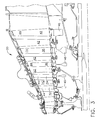
- FIG 3 is an enlarged cross-sectional view of a portion of low pressure turbine 20 (shown in Figure 2).
- low pressure turbine 20 includes five stages 30, wherein each stage 32, 34, 36, 38, and 40, respectively, includes a plurality of circumferentially-spaced stator vanes 42 and a plurality of circumferentially-spaced rotor blades 44, extending from a respective rotor disk 46.
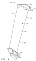
- FIG 4 is an enlarged perspective view of an exemplary rotor blade 50 that may be used with low pressure turbine 20.
- Each blade 50 includes an airfoil 52 and an integral dovetail 54 that is used for mounting blade 50 to a rotor disk, such as rotor disk 46 (shown in Figure 3) in a known manner.
- Each airfoil 52 includes a first contoured sidewall 56 and a second contoured sidewall 58.
- First sidewall 56 is convex and defines a suction side of airfoil 52
- second sidewall 58 is concave and defines a pressure side of airfoil 52.
- Sidewalls 56 and 58 are joined at a leading edge 60 and at an axially-spaced trailing edge 62 of airfoil 52. More specifically, airfoil trailing edge 62 is spaced chordwise and downstream from airfoil leading edge 60.
- First and second sidewalls 56 and 58 respectively, extend longitudinally or radially outward in span from a blade root 64 positioned adjacent dovetail 54, to an airfoil tip 66.
- airfoil tip 66 includes a tip shroud 68 extending radially outward therefrom in a direction away from airfoil 52.
- Tip shroud 68 includes a bottom surface 70, an upper surface 72 that is configured to slidably contact a seal (not shown), leading edge 74, and a trailing edge 76.
- FIG. 5 is top perspective view of a balance clip 100.
- Figure 6 is a bottom perspective view of balance clip 100.
- balance clip 100 is substantially L-shaped and includes a first portion 102 having a first length 104 and a second portion 106 having a second length 108 that is less than first length 104.
- First portion 102 includes a first tab 110 formed unitarily with first portion 102 and second portion 106 includes a second tab 112 formed unitarily with second portion 106.
- Balance clip 100 includes a first hook 114 that is coupled to a first end 116 of first portion 102 and a second hook 118 that is coupled to a second end 120 of first portion 102 and a first end 122 of second portion 106.
- first portion 102, second portion 106, first tab 110, second tab 112, first hook 114, and second hook 118 are integrally formed together to form a unitary balance clip100.
- balance clip 100 is fabricated from a metallic material such as, but not limited to, Inconel 718 and/or AMS 5596.
- FIG 7 is a top perspective view of balance clip 100 shown in Figure 5 coupled to rotor blade 50.
- Figure 8 is a bottom perspective view of balance clip 100 coupled to rotor blade 50.
- balance clip 100 is coupled to an exemplary turbine rotor blade.
- first portion 102 is positioned adjacent tip shroud 68 such that first portion 102 is positioned adjacent first contoured sidewall 56 and second portion 106 is positioned adjacent second contoured sidewall 58.
- First hook 114 is then coupled to tip shroud 68 such that first hook 114 is coupled to leading edge 74.
- Second hook 118 is then coupled to tip shroud 68 such that second hook 118 is coupled to trailing edge 76.
- a plurality of balance clips 100 are coupled to a plurality of turbine rotor blades 50 in the fifth stage 40 of low pressure turbine 20.
- balance clips 100 are coupled to rotor blades 50 in the fifth stage 40 of low pressure turbine 20, low pressure turbine 20 is then rotated at a sufficient speed to ensure that fifth stage 40 is properly balanced.
- balance clips 100 are either coupled to/or removed from low pressure turbine 20 until the desired balance is achieved.
- Each balance clip 100 is then crimped, or forcibly squeezed, to facilitate permanently coupling balance clips 100 to turbine blades 50. More specifically, second hook 118 on each respective balance clip 100 is crimped to trailing edge 76 to facilitate securing balance clip 100 to each respective rotor blade 50.
- first hook 114 and second hook 118 are frictionally coupled to tip shroud 68 to facilitate restraining balance clip 100 axially on tip shroud 68, whereas first tab 110 and second tab 112 facilitate restraining balance clip 100 circumferentially and restrain balance clip 100 from "spinning" around airfoil 52.
- the above-described method and apparatus for assembling a turbine rotor assembly are cost-effective and highly reliable to facilitate balancing the turbine rotor and to facilitate preventing engine failure that may be caused when known balance clips detach from a turbine rotor blade during engine operation.
- prior art balance clip includes three hooks, special tooling and training is required to couple the balance clip to the turbine rotor.
- the balance clip described herein includes only two hooks, no special tooling or training is required to install the balance clip.
- the methods and apparatus described herein facilitate assembling and balancing a gas turbine rotor in a cost-effective and reliable manner.
- the balance clip is not limited to the specific embodiments described herein, but rather, the balance clip may be utilized independently and separately from other components described herein. For example, since the balance clip includes only two hooks, the balance clip may be installed on a variety of rotor blades that include a blade shroud.
Landscapes
- Engineering & Computer Science (AREA)
- Mechanical Engineering (AREA)
- General Engineering & Computer Science (AREA)
- Turbine Rotor Nozzle Sealing (AREA)
Abstract

Description
Claims (10)
- A balance clip (100) for a gas turbine rotor that includes a plurality of turbine blades (50), wherein at least one of the turbine blades includes a blade tip shroud (68) that extends from a leading edge (74) to an opposite trailing edge (76), said balance clip comprises:a first portion (102) having a first length (104) that enables said balance clip to extend between the tip shroud leading and trailing edges and comprises a first hook (114) that is configured to couple to said tip shroud leading edge;a second portion (106) having a second length (108) that is shorter than said first length such that said second portion extends only partially from at least one of the tip shroud trailing and leading edges towards an opposite shroud edge; anda second hook (118) that extends between said first and second portions for coupling said clip to at least one of said tip shroud leading and trailing edges.
- A balance clip (100) in accordance with Claim 1 wherein said balance clip is coupled to a fifth stage (40) low pressure turbine rotor blade (50) using only said first and second hooks (114, 118).
- A balance clip (100) in accordance with Claim 1 wherein said second hook (118) is forcibly squeezed to at least one of the tip shroud leading and trailing edges (74, 76).
- A balance clip (100) in accordance with Claim 1 wherein said balance clip further comprises a substantially L-shaped profile.
- A balance clip (100) in accordance with Claim 1 wherein said first portion (102) further comprises a first tab (110), said second portion (106) comprises a second tab (112), said first and second tabs configured to restrain said balance clip circumferentially around an outer periphery of an airfoil (52) extending radially from the tip shroud (68).
- A balance clip (100) in accordance with Claim 1 wherein said first and second hooks (114, 118) are frictionally coupled to the tip shroud (68).
- A gas turbine engine (10) comprising:a rotor assembly comprising a plurality of circumferentially-spaced rotor blades (50), at least one said rotor blade (50) comprises a blade tip shroud (68) that extends between a leading edge (74) and an opposite trailing edge (76); anda balance clip (100) coupled to said at least one rotor blade, said balance clip comprises a first portion (102) having a first length (104) that enables said balance clip to extend between said tip shroud leading and trailing edges, said first portion comprises a first hook (114) that is configured to couple said clip to said tip shroud leading edge; anda second portion (106) having a second length (108) that is shorter than said first length, said second portion extends only partially from at least one of said tip shroud trailing and leading edges towards an opposite shroud edge.
- A gas turbine engine (10) in accordance with Claim 7 wherein said balance clip (100) further comprises a second hook (118) that extends between said first and second portions (102, 106) for coupling said clip to at least one of said tip shroud leading and trailing edges (74, 76).
- A gas turbine engine (10) in accordance with Claim 7 wherein said balance clip (100) is coupled to said at least one rotor blade (50) using only said first and second hooks (114, 118).
- A gas turbine engine (10) in accordance with Claim 7 wherein said rotor assembly (50) comprises a plurality of balance clips (10), each said balance clip coupled to a respective one of said rotor blades (50).
Applications Claiming Priority (2)
| Application Number | Priority Date | Filing Date | Title |
|---|---|---|---|
| US10/857,234 US7108480B2 (en) | 2004-05-28 | 2004-05-28 | Method and apparatus for balancing turbine rotors |
| US857234 | 2004-05-28 |
Publications (3)
| Publication Number | Publication Date |
|---|---|
| EP1605134A2 true EP1605134A2 (en) | 2005-12-14 |
| EP1605134A3 EP1605134A3 (en) | 2006-09-27 |
| EP1605134B1 EP1605134B1 (en) | 2009-03-04 |
Family
ID=34941366
Family Applications (1)
| Application Number | Title | Priority Date | Filing Date |
|---|---|---|---|
| EP05253066A Ceased EP1605134B1 (en) | 2004-05-28 | 2005-05-18 | Device for balancing a gas turbine rotor and gas turbine engine comprising such a device |
Country Status (5)
| Country | Link |
|---|---|
| US (1) | US7108480B2 (en) |
| EP (1) | EP1605134B1 (en) |
| JP (1) | JP4718899B2 (en) |
| CA (1) | CA2508009C (en) |
| DE (1) | DE602005013022D1 (en) |
Cited By (4)
| Publication number | Priority date | Publication date | Assignee | Title |
|---|---|---|---|---|
| WO2010103552A1 (en) * | 2009-03-09 | 2010-09-16 | Avio S.P.A. | Rotor for turbomachines with shrouded blades |
| CN103982462A (en) * | 2014-05-15 | 2014-08-13 | 北京理工大学 | Wavelike jet method for blade trailing edges |
| EP2808486A1 (en) * | 2013-05-27 | 2014-12-03 | MTU Aero Engines GmbH | Balancing component for a rotor blade arrangement |
| EP3258064A1 (en) * | 2016-06-14 | 2017-12-20 | MTU Aero Engines GmbH | Balancing weight for a rotor blade of a turbine stage |
Families Citing this family (3)
| Publication number | Priority date | Publication date | Assignee | Title |
|---|---|---|---|---|
| US9297258B2 (en) * | 2009-06-16 | 2016-03-29 | General Electric Company | Trapped spring balance weight and rotor assembly |
| US8753081B2 (en) * | 2009-10-02 | 2014-06-17 | Delta T Corporation | Air fence for fan blade |
| US10654577B2 (en) * | 2017-02-22 | 2020-05-19 | General Electric Company | Rainbow flowpath low pressure turbine rotor assembly |
Family Cites Families (8)
| Publication number | Priority date | Publication date | Assignee | Title |
|---|---|---|---|---|
| US2610823A (en) * | 1947-02-11 | 1952-09-16 | Gen Electric | Turbine bucket damping arrangement |
| SU787689A1 (en) * | 1979-01-09 | 1980-12-15 | Предприятие П/Я В-2285 | Axial-flow turbine impeller |
| US5011374A (en) | 1987-11-17 | 1991-04-30 | General Electric Company | Method and apparatus for balancing turbine rotors |
| FR2666266B1 (en) * | 1990-09-05 | 1992-10-30 | Snecma | TOOL FOR DEPOSITING BALANCING MASSES ON TURBINE. |
| US5320487A (en) | 1993-01-19 | 1994-06-14 | General Electric Company | Spring clip made of a directionally solidified material for use in a gas turbine engine |
| JP3111738B2 (en) * | 1993-04-02 | 2000-11-27 | 松下電器産業株式会社 | Blower impeller and its balance weight |
| DE19957030A1 (en) * | 1999-11-26 | 2001-05-31 | Bosch Gmbh Robert | Weighting clip for balancing rotation of rotary body e.g. fan wheel, has pointed tongues at ends of its arms for penetrating surface of rotary body |
| DE60026686T2 (en) * | 2000-12-06 | 2006-10-05 | Techspace Aero S.A. | Stator stage of a compressor |
-
2004
- 2004-05-28 US US10/857,234 patent/US7108480B2/en not_active Expired - Lifetime
-
2005
- 2005-05-18 DE DE602005013022T patent/DE602005013022D1/en not_active Expired - Lifetime
- 2005-05-18 EP EP05253066A patent/EP1605134B1/en not_active Ceased
- 2005-05-19 CA CA2508009A patent/CA2508009C/en not_active Expired - Fee Related
- 2005-05-27 JP JP2005154799A patent/JP4718899B2/en not_active Expired - Fee Related
Cited By (7)
| Publication number | Priority date | Publication date | Assignee | Title |
|---|---|---|---|---|
| WO2010103552A1 (en) * | 2009-03-09 | 2010-09-16 | Avio S.P.A. | Rotor for turbomachines with shrouded blades |
| US9004870B2 (en) | 2009-03-09 | 2015-04-14 | Avio S.P.A. | Rotor for turbomachines with shrouded blades |
| EP2808486A1 (en) * | 2013-05-27 | 2014-12-03 | MTU Aero Engines GmbH | Balancing component for a rotor blade arrangement |
| US9816379B2 (en) | 2013-05-27 | 2017-11-14 | MTU Aero Engines AG | Balancing body for a continuous blade arrangement |
| CN103982462A (en) * | 2014-05-15 | 2014-08-13 | 北京理工大学 | Wavelike jet method for blade trailing edges |
| CN103982462B (en) * | 2014-05-15 | 2016-03-30 | 北京理工大学 | A kind of waveform jetting method of blade trailing edge |
| EP3258064A1 (en) * | 2016-06-14 | 2017-12-20 | MTU Aero Engines GmbH | Balancing weight for a rotor blade of a turbine stage |
Also Published As
| Publication number | Publication date |
|---|---|
| US20050265845A1 (en) | 2005-12-01 |
| CA2508009C (en) | 2013-04-09 |
| US7108480B2 (en) | 2006-09-19 |
| EP1605134A3 (en) | 2006-09-27 |
| DE602005013022D1 (en) | 2009-04-16 |
| JP4718899B2 (en) | 2011-07-06 |
| JP2005337255A (en) | 2005-12-08 |
| CA2508009A1 (en) | 2005-11-28 |
| EP1605134B1 (en) | 2009-03-04 |
Similar Documents
| Publication | Publication Date | Title |
|---|---|---|
| EP1924758B1 (en) | Vane assembly with outer grommets | |
| EP2374997B1 (en) | Component for a gas turbine engine | |
| EP1890008A2 (en) | Rotor blade | |
| US10767504B2 (en) | Flexible damper for turbine blades | |
| EP1926887B1 (en) | Vane assembly with improved vane roots | |
| US9957818B2 (en) | Removably attachable snubber assembly | |
| CA2552214A1 (en) | Blades for a gas turbine engine with integrated sealing plate and method | |
| EP1426555A2 (en) | Method and apparatus for reducing flow across compressor airfoil tips | |
| US7874794B2 (en) | Blade row for a rotary machine and method of fabricating same | |
| CA2622013C (en) | Vane assembly with grommet | |
| EP1605134B1 (en) | Device for balancing a gas turbine rotor and gas turbine engine comprising such a device | |
| US20160102568A1 (en) | Power turbine heat shield architecture | |
| EP2586984A2 (en) | Turbine rotor blade and corresponding turbomachine | |
| CN204212817U (en) | Comprise the turbo machine of the non-destructive fastener element for connected element | |
| EP2615251B1 (en) | Rotor for a turbomachine | |
| EP1760268B1 (en) | Apparatus for controlling contact within stator assemblies | |
| EP3088666A1 (en) | Blade/disk dovetail backcut for blade/disk stress reduction for a first stage of a turbomachine | |
| CA2597443A1 (en) | Vane assembly with improved vane roots | |
| WO2019046006A1 (en) | Advanced geometry platforms for turbine blades |
Legal Events
| Date | Code | Title | Description |
|---|---|---|---|
| PUAI | Public reference made under article 153(3) epc to a published international application that has entered the european phase |
Free format text: ORIGINAL CODE: 0009012 |
|
| AK | Designated contracting states |
Kind code of ref document: A2 Designated state(s): AT BE BG CH CY CZ DE DK EE ES FI FR GB GR HU IE IS IT LI LT LU MC NL PL PT RO SE SI SK TR |
|
| AX | Request for extension of the european patent |
Extension state: AL BA HR LV MK YU |
|
| PUAL | Search report despatched |
Free format text: ORIGINAL CODE: 0009013 |
|
| AK | Designated contracting states |
Kind code of ref document: A3 Designated state(s): AT BE BG CH CY CZ DE DK EE ES FI FR GB GR HU IE IS IT LI LT LU MC NL PL PT RO SE SI SK TR |
|
| AX | Request for extension of the european patent |
Extension state: AL BA HR LV MK YU |
|
| RIC1 | Information provided on ipc code assigned before grant |
Ipc: F01D 5/02 20060101AFI20050715BHEP Ipc: F04D 29/66 20060101ALI20060824BHEP |
|
| 17P | Request for examination filed |
Effective date: 20070327 |
|
| AKX | Designation fees paid |
Designated state(s): DE FR GB |
|
| 17Q | First examination report despatched |
Effective date: 20070511 |
|
| GRAP | Despatch of communication of intention to grant a patent |
Free format text: ORIGINAL CODE: EPIDOSNIGR1 |
|
| GRAS | Grant fee paid |
Free format text: ORIGINAL CODE: EPIDOSNIGR3 |
|
| GRAA | (expected) grant |
Free format text: ORIGINAL CODE: 0009210 |
|
| AK | Designated contracting states |
Kind code of ref document: B1 Designated state(s): DE FR GB |
|
| REG | Reference to a national code |
Ref country code: GB Ref legal event code: FG4D |
|
| REF | Corresponds to: |
Ref document number: 602005013022 Country of ref document: DE Date of ref document: 20090416 Kind code of ref document: P |
|
| PLBE | No opposition filed within time limit |
Free format text: ORIGINAL CODE: 0009261 |
|
| STAA | Information on the status of an ep patent application or granted ep patent |
Free format text: STATUS: NO OPPOSITION FILED WITHIN TIME LIMIT |
|
| 26N | No opposition filed |
Effective date: 20091207 |
|
| REG | Reference to a national code |
Ref country code: FR Ref legal event code: PLFP Year of fee payment: 12 |
|
| REG | Reference to a national code |
Ref country code: FR Ref legal event code: PLFP Year of fee payment: 13 |
|
| PGFP | Annual fee paid to national office [announced via postgrant information from national office to epo] |
Ref country code: DE Payment date: 20170530 Year of fee payment: 13 Ref country code: FR Payment date: 20170525 Year of fee payment: 13 Ref country code: GB Payment date: 20170530 Year of fee payment: 13 |
|
| REG | Reference to a national code |
Ref country code: DE Ref legal event code: R119 Ref document number: 602005013022 Country of ref document: DE |
|
| GBPC | Gb: european patent ceased through non-payment of renewal fee |
Effective date: 20180518 |
|
| PG25 | Lapsed in a contracting state [announced via postgrant information from national office to epo] |
Ref country code: GB Free format text: LAPSE BECAUSE OF NON-PAYMENT OF DUE FEES Effective date: 20180518 Ref country code: DE Free format text: LAPSE BECAUSE OF NON-PAYMENT OF DUE FEES Effective date: 20181201 Ref country code: FR Free format text: LAPSE BECAUSE OF NON-PAYMENT OF DUE FEES Effective date: 20180531 |